EP1174957A2 - Electrical card connector - Google Patents
Electrical card connector Download PDFInfo
- Publication number
- EP1174957A2 EP1174957A2 EP01116962A EP01116962A EP1174957A2 EP 1174957 A2 EP1174957 A2 EP 1174957A2 EP 01116962 A EP01116962 A EP 01116962A EP 01116962 A EP01116962 A EP 01116962A EP 1174957 A2 EP1174957 A2 EP 1174957A2
- Authority
- EP
- European Patent Office
- Prior art keywords
- card
- eject plate
- engaging
- push rod
- case
- Prior art date
- Legal status (The legal status is an assumption and is not a legal conclusion. Google has not performed a legal analysis and makes no representation as to the accuracy of the status listed.)
- Granted
Links
Images





Classifications
-
- G—PHYSICS
- G06—COMPUTING OR CALCULATING; COUNTING
- G06K—GRAPHICAL DATA READING; PRESENTATION OF DATA; RECORD CARRIERS; HANDLING RECORD CARRIERS
- G06K13/00—Conveying record carriers from one station to another, e.g. from stack to punching mechanism
- G06K13/02—Conveying record carriers from one station to another, e.g. from stack to punching mechanism the record carrier having longitudinal dimension comparable with transverse dimension, e.g. punched card
- G06K13/08—Feeding or discharging cards
- G06K13/0806—Feeding or discharging cards using an arrangement for ejection of an inserted card
- G06K13/0825—Feeding or discharging cards using an arrangement for ejection of an inserted card the ejection arrangement being of the push-push kind
-
- G—PHYSICS
- G06—COMPUTING OR CALCULATING; COUNTING
- G06K—GRAPHICAL DATA READING; PRESENTATION OF DATA; RECORD CARRIERS; HANDLING RECORD CARRIERS
- G06K13/00—Conveying record carriers from one station to another, e.g. from stack to punching mechanism
- G06K13/02—Conveying record carriers from one station to another, e.g. from stack to punching mechanism the record carrier having longitudinal dimension comparable with transverse dimension, e.g. punched card
- G06K13/08—Feeding or discharging cards
-
- G—PHYSICS
- G06—COMPUTING OR CALCULATING; COUNTING
- G06K—GRAPHICAL DATA READING; PRESENTATION OF DATA; RECORD CARRIERS; HANDLING RECORD CARRIERS
- G06K13/00—Conveying record carriers from one station to another, e.g. from stack to punching mechanism
- G06K13/02—Conveying record carriers from one station to another, e.g. from stack to punching mechanism the record carrier having longitudinal dimension comparable with transverse dimension, e.g. punched card
- G06K13/08—Feeding or discharging cards
- G06K13/0806—Feeding or discharging cards using an arrangement for ejection of an inserted card
-
- H—ELECTRICITY
- H01—ELECTRIC ELEMENTS
- H01R—ELECTRICALLY-CONDUCTIVE CONNECTIONS; STRUCTURAL ASSOCIATIONS OF A PLURALITY OF MUTUALLY-INSULATED ELECTRICAL CONNECTING ELEMENTS; COUPLING DEVICES; CURRENT COLLECTORS
- H01R13/00—Details of coupling devices of the kinds covered by groups H01R12/70 or H01R24/00 - H01R33/00
- H01R13/62—Means for facilitating engagement or disengagement of coupling parts or for holding them in engagement
- H01R13/629—Additional means for facilitating engagement or disengagement of coupling parts, e.g. aligning or guiding means, levers, gas pressure electrical locking indicators, manufacturing tolerances
- H01R13/633—Additional means for facilitating engagement or disengagement of coupling parts, e.g. aligning or guiding means, levers, gas pressure electrical locking indicators, manufacturing tolerances for disengagement only
- H01R13/635—Additional means for facilitating engagement or disengagement of coupling parts, e.g. aligning or guiding means, levers, gas pressure electrical locking indicators, manufacturing tolerances for disengagement only by mechanical pressure, e.g. spring force
Definitions
- the present invention relates to card connectors for connecting a card to a circuit board and, particularly, to a card connector for holding a card for a mobile device.
- Japanese patent application Kokai No. 11-135192 discloses such a card connector as described above.
- This card connector comprises a body, a slider pushed into the body along with a card, a spring provided between the slider and the body, and a cam mechanism made up of a cam member and a pin member. The cam mechanism locks the slider.
- the card is inserted/removed by the "push-push operation" or pushing an edge of the card.
- the push-push type connector requires a play space in the card insertion direction, increasing the depth of the connector against miniaturization trends.
- the sliding length between the card contact and the connector contact is so large that the life of the contacts is cut short.
- the edge of a card must be protruded from the mobile device so that the card can be damaged or fall out of the connector when the mobile device drops.
- the gripping power of a card is determined by the spring force of the lock mechanism so that it is necessary to replace the lock mechanism for adjusting the gripping power, requiring more labor and cost.
- the eject member and the lock mechanism are too complex to reduce the size of the device and the manufacturing cost.
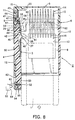
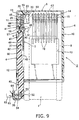
- a card connector comprises a case 2 for receiving a removable card 1 (Figs. 8-10), an eject plate 3 provided in the case 2 for sliding along with the card 1, a push rod 4 provided outside the eject plate 3, and a cam member 5 provided between the push rod 4 and the case 2 for rotation.
- the case 2 is made up of a case body 6 made of a synthetic resin, for example, and a case cover 7 made of a metal sheet to cover the case body 6.
- the case body 6 has a rectangular bottom plate 8, a rear wall 9, a right side wall 10, and a left side wall 11.
- a cut-out 12 is provided in the middle of the left side wall 11.
- the front edge of the bottom plate 8 is tapered and a rectangular opening 13 is provided in the middle of the bottom plate 8.
- Ten (10) terminals 14 are arranged in parallel on the bottom plate 8 behind the rectangular opening 13. The rear end of each terminal 14 is bent upwardly to provide a contact section 15 and the front end is bent downwardly through the rectangular opening 13 to provide a connection section 16.
- a first spring mounting groove 17 is provided in the bottom plate 8 at the left rear corner along the left side wall 11 and a circular hole 18 is provided in front of the first spring mounting groove 17.
- An abutting section 19 is provided at the left end of the rear wall 9 adjacent to the left side wall 11 and is made higher and thicker than the rest of the rear wall 9.
- An obliquely cut portion 20 is provided at the upper right corner of the abutting section 19.
- a first spring engaging recess 21 is provided in the left portion of the abutting section 19 corresponding to the first spring mounting groove 17 and a second spring engaging recess 22 is provided above the first spring engaging recess.
- the case cover 7 has depending rear and side flanges and a top plate 23 with a rectangular opening 24 provided at a position corresponding to the bottom opening 13.
- the top and bottom openings 24 and 13 are used for connecting the connection sections 16 to a circuit board (not shown) and ventilating the heat that is generated during the connecting operation.
- First and second slits 25 and 26 are provided in the left portion or the top plate 23 aligned in a line in the card insertion/removal direction. A major edge of each slit 25 or 26 is bent downwardly to provide a first or second projection piece 27 or 28.
- the eject plate 3 comprises a slide section 29 extending in the card insertion/removal direction and an engaging plate 30 provided on the rear side face of the slide section 29.
- a fine groove 31 and a second spring groove 32 are provided in the top of the slide section 29 to receive the first projection piece 27 and the second spring 33, respectively.
- Rear and front depending walls 34 and 35 are provided on the inner side of the slide section 29 with a gap 36 between them.
- a metallic engaging piece 37 is attached to the outer face of the front depending wall 35 such that a J-shaped engaging projection 38 lies beside the gap 36 and projects inwardly from an imagined line connecting the depending walls 34 and 35.
- outer and front jaw sections 39 and 40 extend outwardly and forwardly, respectively, from the lower end of the rear depending wall 34 such that their lower faces are flush with the lower face of the engaging section 30.
- the push rod 4 comprises a rear plate 41 for sliding along the rear left side wall 11, an L-shaped central section 42 for sliding within the gap 12, and a front rectangular block 43 for sliding along the front left side wall 11 such that the eject plate 3 slides along the rear plate 41 and the central section 42.
- a round rod 44 extends rearwardly from the rear end of the rear plate 41 to engage a first spring 45.
- a step-down portion 46 is provided on the rear section 41 and a guide groove 47 extends outwardly from the inner edge of the step-down portion 46.
- the central section 42 has a sloping inner face 48 tapered toward the rear end and a cut-out portion 49 at its front end.
- An engaging wall 50 extends outwardly from the central section 42 beyond the rear and front sections 41 and 43 so that the front and rear faces thereof abut against the rear and front ends of the front and rear left side walls 11, respectively.
- the front section 43 is protruded more inwardly than the rear and central sections 41 and 42 and a fine groove 51 extends forwardly from the rear end of the front section 43 to receive the second projecting piece 28.
- the front portion 52 of the front section 43 is made thinner than the other portion thereof and a circular recess 53 extends inwardly from the outer face thereof to receive a third spring 55 therein.
- a removable push button 54 is attached to the front portion 52 is biased outwardly by the third spring 55.
- a notch 64 is provided in the case 63, to which the card connector is attached, beside the push button 54 and a card detecting switch 65 is provided in the notch 64.
- the cam member 5 comprises a short shaft 56 for engagement with the round hole 18, a semi-circular engaging plate 57, and a top column 58 eccentrically provided on the engaging plate 57 for engagement with the guide groove 47 such that, as Figs. 5-6, 8, and 10 show, the top column 58 is positioned more rearwardly than the axis of the short shaft 56 with the curved face of the engaging plate 57 facing outwardly and, as Figs. 7 and 9 show, it is positioned more outwardly than the axis or the short shaft 56 with the curved face of the engaging plate 57 facing forwardly. That is, the top column 58 is positioned inwardly in the guiding groove 47 when the curved face of the engaging plate 57 faces outwardly and outwardly in the guiding groove 47 when the curved face of the engaging plate 57 faces forwardly.
- the card 1 will be described below with reference to Figs. 8-10.
- the card 1 has a rectangular shape, with a rounded front left corner 59, and a first engaging recess 60 provided in the lower face of the front left corner 59.
- a second engaging recess 61 is provided in the lower face of the card 1 behind the first one, extending inwardly from the left edge of the card 1.
- a plurality of contact points 62 are provided on the front edge of the card 1 corresponding to the terminals 14.
- the eject plate 3 Before the card 1 is inserted in the case 2, the eject plate 3 is pushed forwardly by the second spring 33 so that the front end of the slide section 29 abuts on the rear face of the front section 43 of the push rod 4, As Figs 5 and 8 show, the engaging plate 57 of the cam member 5 is prevented by the outward jaw portion 39 from counterclockwise rotation-to keep the curved face to face outwardly. That is, the top column 58 is positioned more forwardly than the axis of the short shaft 56, keeping the push rod 4 at such a position as shown in Fig. 8 and the push button 54 to engage the case 63, fitting over the front portion 52.
- Fig. 8 shows, when the card 1 is inserted into the case 2, the engaging projection 38 abuts on the left side of the card 1 and engages the second engaging recess 61 and the engaging section 30 engages the first engaging recess 60. During this time, the eject plate 3 and the push rod 4 keep the initial conditions. When the card 1 is further inserted into the case 2, the eject plate 3 is moved rearwardly along the push rod 4 along with the card 1 against the second spring 33.
- FIGs. 7 and 9 show, when the front end of the card 1 abuts on the rear wall 9 and the rear end of the engaging section 30 abuts on the abutment section 19, the engaging plate 57 rotates counterclockwise and engages the front jaw portion 40. Consequently, the top column 58 is positioned more outwardly than the axis of the short shaft 56, the push rod 4 slides forwardly, and the push button 54 is released from the housing 63.
- the push button 54 is separated from the front portion 52 by the third spring 55 for contact with the card detecting switch 65, indicating that the card 1 now is held in the case 2.
- the leftward movement of the engaging plate 37 is restricted by the inner side face of the rear section 41 to lock the engagement between the engaging projection 38 and the second engaging recess 61.
- the push button 54 is depressed to the right against the third spring 55 to-fit over the front portion 52 and the push rod 4 pushed rearwardly.
- the top column 58 is moved more rearwardly than the axis of the short shaft 56 and the engaging plate 57 rotates clockwise. Consequently, the curved face of the engaging plate 57 faces outwardly, releasing the engagement between the engaging plate 57 and the front jaw portion 40.
- the eject plate 3 is moved forwardly together with the card 1 by the second spring 33 along the push rod 4 to the original position.
- the cut-out portion 49 is positioned on the left side of the engaging projection 38 so that when the card 1 is pulled, the engaging projection 38 is flexed toward the left, releasing the engagement between the engaging projection 38 and the second engaging recess 61 to facilitate the removal of the card 1.
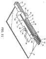
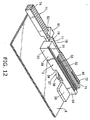
- a push rod 71 is provided outside the ejector plate 3 and composed of a rectangular rear section 72 for sliding on the rear left side wall 11, a central section 73 for sliding in the gap 12, and a rectangular front section 74 for sliding on the front left side wall 11.
- a first spring mounting groove 75 extends forwardly from the rear end of the rear section 72 to receive a first spring 45 therein.
- An indented portion 76 is provided in the outside of the central section 73 and a leaf spring 77 extends forwardly from the rear end of the indented portion 76. Alternatively, the leaf spring 77 may extend from the case 1.
- a cut-out portion 78 is provided in the front portion of the central section 73 and a wide tapered face 79 is provided on the front end of the cut-out portion 78.
- a guiding ridge 80 extends in the bottom plate 8 of the case body 6 in a direction perpendicular to the card insertion/removal direction and a cam member 81 for sliding along the guiding ridge 80 is biased inwardly by the leaf spring 77.
- the cam member 81 has a triangular shape and a sloping front face 82 that has the same slant angle as that of the tapered face 79.
- the push rod 71 is depressed against the third spring 55.
- the tapered face 79 of the push rod 71 pushes the sloping face 82 of the cam member 81 outwardly against the leaf spring 77 along the guiding ridge 80 so that the engagement between the cam member 81 and the front end of the slide section 29 is released (Fig. 12).
- the eject plate 3 is moved forwardly together with the card 1 by the second spring 33 to the original position as shown in Fig. 11.
- the engaging projection 38 is flexed to the left so that the engagement between the engaging projection 38 and the second engaging recess 61 is released to eject the card.
- FIG. 15 shows, the engaging plate 30 for engagement with the first engaging recess 60 of the card 1 is replaced by an abutting portion 83 on which the front end of the card 1 abuts.
- a wrong insertion preventive portion 84 is provided on the rear left corner of the bottom plate 8 to prevent the card 1 from being inserted into the case 2 upside down.
- the connection sections 16 of terminals 14 extend to the outside.
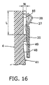
- a stepped portion 85 having a length of L and a depth of W is provided in the inside of the rear end portion 41 or 72 of the push rod 4 or 71. If a force is applied to the card 1 held in the case 2, the engaging member 37 is flexed to avoid damage to the connector. The amount of flexure of the engaging member 37 is adjusted by changing the length (L) and/or depth (W) of the stepped portion 85. The portion for restricting the outward movement of the engaging projection 38 and the stepped portion 85 may be provided on the case 2 instead of the push rod 4 or 71.
- the card connector according to the invention may be used for a variety of cards including an IC card that is mounted in a mobile device.
- the card connector according to the invention requires no space for play that has been required for the push-push operation system. Since the card is locked by the cam member, it does not fall from the connector even if the mobile device is dropped. To remove the card, it is only necessary that the push rod is depressed lightly. Also, it is easy to adjust the force with which the card is held. The structure is simple and the number of parts is so small that the manufacturing cost is reduced.
Landscapes
- Physics & Mathematics (AREA)
- General Physics & Mathematics (AREA)
- Engineering & Computer Science (AREA)
- Theoretical Computer Science (AREA)
- Coupling Device And Connection With Printed Circuit (AREA)
- Details Of Connecting Devices For Male And Female Coupling (AREA)
- Credit Cards Or The Like (AREA)
Abstract
Description
Claims (7)
- A card connector for electrically connecting to a circuit board a removable card having an engaging recess on a side thereof, comprising:a case for holding said removable card therein;an eject plate biased in a card removal direction for sliding together with said removable card;an engaging member provided on said ejector plate and having an engaging projection for engagement with said engaging recess;a push rod provided outside said eject plate and biased in said card removal direction and having a front portion projecting said case;a cam member biased to move, when said removable card is inserted into a predetermined position, toward said eject plate for engagement with said eject plate to lock said removable card at said predetermined position and, when said push rod is depressed, moved away from said eject plate against said bias to release said eject plate from said engagement.
- The card connector according to claim 1, wherein said cam member comprises an engaging plate for rotation between said case and said push rod and a top column eccentrically provided on said engaging member for engagement with said push rod such that when said removable card is inserted into said predetermined card, it is rotated outwardly while said engaging member is rotated to and engaged with said eject plate to lock said removable card at said predetermined position and, when said push rod is depressed, it is rotated inwardly while said engaging plate is rotated to the eject plate to release the eject plate from said engagement.
- The card connector according to claim 1, which further comprises spring means for biasing said cam member to said eject plate so that when said removable card is inserted into said case at said predetermined position, said cam member slides to and engages with said eject plate to lock said card at said predetermined position and, when said push rod is depressed, said cam member slides away from said eject plate to release said engagement between said cam member and said eject plate.
- The card connector according to one of claims 1-3, which further comprises a push button provided at a rear end of said push rod and biased outwardly so that when said card is not in said case, it is fitted over said rear end of said push rod and, when said card is held in said case, said push rod is moved in said card removal direction and said push button is separated from said rear end and brought into contact with a card detecting switch on a housing.
- The card connector according to one of claims 1-4, wherein said push rod is provided with means for restricting outward movement of said engaging member with said removable card held in said case.
- The card connector according to claim 5, wherein said means is provided with a stepped down portion having a size changed to adjust changes of said engaging member.
- A card connector for electrically connecting a removable card to a circuit board, comprising:a case for holding said removable card;an eject plate biased in a card removal direction for sliding together with said removable card;an engaging member provided on said eject plate so as to be laterally flexible and having an engaging projection for engagement with said engaging recess of said removable card;locking means for locking, when said removable card is inserted into said predetermined position, said eject plate at said predetermined position to hold said removable card at said predetermined position; andrestricting means for restricting outward movement of said engaging member when said removable card is held at said predetermined position, said restricting means having a stepped portion changed so as to adjust flexure of said engaging member.
Applications Claiming Priority (2)
| Application Number | Priority Date | Filing Date | Title |
|---|---|---|---|
| JP2000216847A JP2002033158A (en) | 2000-07-18 | 2000-07-18 | Card connector |
| JP2000216847 | 2000-07-18 |
Publications (3)
| Publication Number | Publication Date |
|---|---|
| EP1174957A2 true EP1174957A2 (en) | 2002-01-23 |
| EP1174957A3 EP1174957A3 (en) | 2003-01-15 |
| EP1174957B1 EP1174957B1 (en) | 2007-01-24 |
Family
ID=18712041
Family Applications (1)
| Application Number | Title | Priority Date | Filing Date |
|---|---|---|---|
| EP01116962A Expired - Lifetime EP1174957B1 (en) | 2000-07-18 | 2001-07-11 | Electrical card connector |
Country Status (5)
| Country | Link |
|---|---|
| US (1) | US20020008142A1 (en) |
| EP (1) | EP1174957B1 (en) |
| JP (1) | JP2002033158A (en) |
| DE (1) | DE60126201T2 (en) |
| TW (1) | TW492583U (en) |
Cited By (1)
| Publication number | Priority date | Publication date | Assignee | Title |
|---|---|---|---|---|
| EP1916776A3 (en) * | 2006-10-23 | 2011-12-14 | Samsung Electronics Co., Ltd. | Apparatus for detachably installing a smart card in a portable terminal |
Families Citing this family (14)
| Publication number | Priority date | Publication date | Assignee | Title |
|---|---|---|---|---|
| WO2002074372A2 (en) | 2001-03-15 | 2002-09-26 | The Government Of The United States Of America As Represented By The Secretary Of The Department Of Health And Human Services | Nebulizer having cooling chamber |
| TWI322382B (en) * | 2005-12-12 | 2010-03-21 | Hon Hai Prec Ind Co Ltd | Electrical card connector |
| CN100440625C (en) * | 2005-12-14 | 2008-12-03 | 富士康(昆山)电脑接插件有限公司 | electronic card connector |
| JP4192981B2 (en) * | 2006-02-23 | 2008-12-10 | ソニー株式会社 | Recording media holding device |
| JP2008277194A (en) * | 2007-05-02 | 2008-11-13 | Yamaichi Electronics Co Ltd | Manual feed connector |
| TWI478650B (en) * | 2009-05-18 | 2015-03-21 | Hon Hai Prec Ind Co Ltd | Installing structure for hard disk drive |
| CN102006760B (en) * | 2009-08-28 | 2013-04-24 | 鸿富锦精密工业(深圳)有限公司 | server |
| CN102005234A (en) * | 2009-08-28 | 2011-04-06 | 鸿富锦精密工业(深圳)有限公司 | Hard disc fixing device |
| TWM388754U (en) * | 2010-03-01 | 2010-09-11 | Hon Hai Prec Ind Co Ltd | Card connector |
| JP2011222314A (en) * | 2010-04-09 | 2011-11-04 | Panasonic Corp | Card mounting device and electronic device |
| KR101201667B1 (en) * | 2011-03-28 | 2012-11-15 | 한국몰렉스 주식회사 | Socket for micro Subscriber Identification Module card |
| US9025335B2 (en) * | 2012-04-30 | 2015-05-05 | Nokia Corporation | Apparatus for moving a card reader |
| JP5921354B2 (en) * | 2012-06-18 | 2016-05-24 | タイコエレクトロニクスジャパン合同会社 | Card connector |
| JP5579294B1 (en) | 2013-03-12 | 2014-08-27 | モレックス インコーポレイテド | Card connector |
Family Cites Families (2)
| Publication number | Priority date | Publication date | Assignee | Title |
|---|---|---|---|---|
| JP3248068B2 (en) * | 1997-10-27 | 2002-01-21 | ホシデン株式会社 | Card connector |
| FR2779562B1 (en) * | 1998-06-09 | 2001-01-19 | Valeo Securite Habitacle | ARRANGEMENT FOR LOCKING A DATA MEDIUM IN A DATA EXCHANGE DEVICE |
-
2000
- 2000-07-18 JP JP2000216847A patent/JP2002033158A/en active Pending
-
2001
- 2001-04-09 TW TW090205434U patent/TW492583U/en unknown
- 2001-07-03 US US09/897,616 patent/US20020008142A1/en not_active Abandoned
- 2001-07-11 EP EP01116962A patent/EP1174957B1/en not_active Expired - Lifetime
- 2001-07-11 DE DE60126201T patent/DE60126201T2/en not_active Expired - Fee Related
Cited By (2)
| Publication number | Priority date | Publication date | Assignee | Title |
|---|---|---|---|---|
| EP1916776A3 (en) * | 2006-10-23 | 2011-12-14 | Samsung Electronics Co., Ltd. | Apparatus for detachably installing a smart card in a portable terminal |
| US8150466B2 (en) | 2006-10-23 | 2012-04-03 | Samsung Electronics Co., Ltd. | Apparatus for detachably installing a smart card in a portable terminal |
Also Published As
| Publication number | Publication date |
|---|---|
| TW492583U (en) | 2002-06-21 |
| US20020008142A1 (en) | 2002-01-24 |
| DE60126201T2 (en) | 2007-11-22 |
| EP1174957A3 (en) | 2003-01-15 |
| JP2002033158A (en) | 2002-01-31 |
| DE60126201D1 (en) | 2007-03-15 |
| EP1174957B1 (en) | 2007-01-24 |
Similar Documents
| Publication | Publication Date | Title |
|---|---|---|
| US6394827B2 (en) | Card connector | |
| US6648694B2 (en) | Connector for memory card | |
| US6976879B2 (en) | Card connector | |
| EP1174957B1 (en) | Electrical card connector | |
| EP1193807B1 (en) | Card connector | |
| JP3830852B2 (en) | Card connector device | |
| EP1172899A1 (en) | Connector device for card with detection switch for detecting fitting of card | |
| JP4585963B2 (en) | Card connector | |
| CN101099269B (en) | Card connector | |
| JP2004039437A (en) | Connector device for card | |
| US6319028B1 (en) | Electrical connector equipped with an improved ejector mechanism | |
| US6934159B2 (en) | Card connector | |
| US20070202750A1 (en) | Card connector | |
| US20040092146A1 (en) | Electrical card connector having card retention mechanism integrally formed with an ejector | |
| EP1605393B1 (en) | Card connector | |
| US5599197A (en) | Electrical connector for IC card | |
| JP2005209575A (en) | Connector for card | |
| JP4332133B2 (en) | Memory card socket | |
| US8303321B1 (en) | Card connector anti-misinserting a micro SD card | |
| US6159026A (en) | Electrical card connector | |
| JP2007287438A (en) | Electronic card connector | |
| EP0963144A1 (en) | Card ejecting device | |
| JP4596825B2 (en) | Memory card socket | |
| JP4023394B2 (en) | Memory card socket | |
| JP4676525B2 (en) | Card connector assembly |
Legal Events
| Date | Code | Title | Description |
|---|---|---|---|
| PUAI | Public reference made under article 153(3) epc to a published international application that has entered the european phase |
Free format text: ORIGINAL CODE: 0009012 |
|
| AK | Designated contracting states |
Kind code of ref document: A2 Designated state(s): AT BE CH CY DE DK ES FI FR GB GR IE IT LI LU MC NL PT SE TR |
|
| AX | Request for extension of the european patent |
Free format text: AL;LT;LV;MK;RO;SI |
|
| PUAL | Search report despatched |
Free format text: ORIGINAL CODE: 0009013 |
|
| AK | Designated contracting states |
Kind code of ref document: A3 Designated state(s): AT BE CH CY DE DK ES FI FR GB GR IE IT LI LU MC NL PT SE TR |
|
| AX | Request for extension of the european patent |
Free format text: AL;LT;LV;MK;RO;SI |
|
| RIC1 | Information provided on ipc code assigned before grant |
Free format text: 7H 01R 13/635 A, 7G 06K 13/08 B |
|
| 17P | Request for examination filed |
Effective date: 20030530 |
|
| AKX | Designation fees paid |
Designated state(s): DE FR GB |
|
| GRAP | Despatch of communication of intention to grant a patent |
Free format text: ORIGINAL CODE: EPIDOSNIGR1 |
|
| GRAS | Grant fee paid |
Free format text: ORIGINAL CODE: EPIDOSNIGR3 |
|
| GRAA | (expected) grant |
Free format text: ORIGINAL CODE: 0009210 |
|
| AK | Designated contracting states |
Kind code of ref document: B1 Designated state(s): DE FR GB |
|
| REG | Reference to a national code |
Ref country code: GB Ref legal event code: FG4D |
|
| REF | Corresponds to: |
Ref document number: 60126201 Country of ref document: DE Date of ref document: 20070315 Kind code of ref document: P |
|
| ET | Fr: translation filed | ||
| PLBE | No opposition filed within time limit |
Free format text: ORIGINAL CODE: 0009261 |
|
| STAA | Information on the status of an ep patent application or granted ep patent |
Free format text: STATUS: NO OPPOSITION FILED WITHIN TIME LIMIT |
|
| 26N | No opposition filed |
Effective date: 20071025 |
|
| GBPC | Gb: european patent ceased through non-payment of renewal fee |
Effective date: 20070711 |
|
| PG25 | Lapsed in a contracting state [announced via postgrant information from national office to epo] |
Ref country code: DE Free format text: LAPSE BECAUSE OF NON-PAYMENT OF DUE FEES Effective date: 20080201 |
|
| PG25 | Lapsed in a contracting state [announced via postgrant information from national office to epo] |
Ref country code: GB Free format text: LAPSE BECAUSE OF NON-PAYMENT OF DUE FEES Effective date: 20070711 |
|
| REG | Reference to a national code |
Ref country code: FR Ref legal event code: ST Effective date: 20080331 |
|
| PG25 | Lapsed in a contracting state [announced via postgrant information from national office to epo] |
Ref country code: FR Free format text: LAPSE BECAUSE OF NON-PAYMENT OF DUE FEES Effective date: 20070731 |