EP1174950A2 - Electrical connection box and vehicle including it - Google Patents
Electrical connection box and vehicle including it Download PDFInfo
- Publication number
- EP1174950A2 EP1174950A2 EP01305703A EP01305703A EP1174950A2 EP 1174950 A2 EP1174950 A2 EP 1174950A2 EP 01305703 A EP01305703 A EP 01305703A EP 01305703 A EP01305703 A EP 01305703A EP 1174950 A2 EP1174950 A2 EP 1174950A2
- Authority
- EP
- European Patent Office
- Prior art keywords
- bus bars
- voltage
- insulation material
- battery
- battery structure
- Prior art date
- Legal status (The legal status is an assumption and is not a legal conclusion. Google has not performed a legal analysis and makes no representation as to the accuracy of the status listed.)
- Granted
Links
- 239000012774 insulation material Substances 0.000 claims abstract description 28
- 229920005989 resin Polymers 0.000 claims description 32
- 239000011347 resin Substances 0.000 claims description 32
- 239000000463 material Substances 0.000 claims description 7
- 238000002485 combustion reaction Methods 0.000 claims description 4
- 230000000694 effects Effects 0.000 claims description 3
- 238000009413 insulation Methods 0.000 description 9
- 238000000465 moulding Methods 0.000 description 6
- 229920003002 synthetic resin Polymers 0.000 description 4
- 239000000057 synthetic resin Substances 0.000 description 4
- XLYOFNOQVPJJNP-UHFFFAOYSA-N water Substances O XLYOFNOQVPJJNP-UHFFFAOYSA-N 0.000 description 3
- 238000010276 construction Methods 0.000 description 2
- 239000000446 fuel Substances 0.000 description 2
- 238000004519 manufacturing process Methods 0.000 description 2
- 238000000034 method Methods 0.000 description 2
- 150000003839 salts Chemical class 0.000 description 2
- 238000005452 bending Methods 0.000 description 1
- 238000010586 diagram Methods 0.000 description 1
- 238000002474 experimental method Methods 0.000 description 1
- 238000002844 melting Methods 0.000 description 1
- 230000008018 melting Effects 0.000 description 1
- 239000002184 metal Substances 0.000 description 1
- 238000012986 modification Methods 0.000 description 1
- 230000004048 modification Effects 0.000 description 1
- 239000011265 semifinished product Substances 0.000 description 1
- 239000000758 substrate Substances 0.000 description 1
Images



Classifications
-
- H—ELECTRICITY
- H01—ELECTRIC ELEMENTS
- H01R—ELECTRICALLY-CONDUCTIVE CONNECTIONS; STRUCTURAL ASSOCIATIONS OF A PLURALITY OF MUTUALLY-INSULATED ELECTRICAL CONNECTING ELEMENTS; COUPLING DEVICES; CURRENT COLLECTORS
- H01R9/00—Structural associations of a plurality of mutually-insulated electrical connecting elements, e.g. terminal strips or terminal blocks; Terminals or binding posts mounted upon a base or in a case; Bases therefor
- H01R9/22—Bases, e.g. strip, block, panel
- H01R9/24—Terminal blocks
- H01R9/2425—Structural association with built-in components
-
- H—ELECTRICITY
- H01—ELECTRIC ELEMENTS
- H01R—ELECTRICALLY-CONDUCTIVE CONNECTIONS; STRUCTURAL ASSOCIATIONS OF A PLURALITY OF MUTUALLY-INSULATED ELECTRICAL CONNECTING ELEMENTS; COUPLING DEVICES; CURRENT COLLECTORS
- H01R2201/00—Connectors or connections adapted for particular applications
- H01R2201/26—Connectors or connections adapted for particular applications for vehicles
-
- H—ELECTRICITY
- H01—ELECTRIC ELEMENTS
- H01R—ELECTRICALLY-CONDUCTIVE CONNECTIONS; STRUCTURAL ASSOCIATIONS OF A PLURALITY OF MUTUALLY-INSULATED ELECTRICAL CONNECTING ELEMENTS; COUPLING DEVICES; CURRENT COLLECTORS
- H01R25/00—Coupling parts adapted for simultaneous co-operation with two or more identical counterparts, e.g. for distributing energy to two or more circuits
- H01R25/16—Rails or bus-bars provided with a plurality of discrete connecting locations for counterparts
- H01R25/161—Details
- H01R25/162—Electrical connections between or with rails or bus-bars
Definitions
- the present invention relates to a vehicle, such as an automobile, having an internal combustion engine, batteries powering electrical devices on the vehicle and an electrical connection box which is mounted on a vehicle, and also to an electrical connection box for use in such a vehicle.
- Normally one secondary, i.e. rechargeable, battery having a rated voltage of 12V and a maximum nominal voltage of 14V is mounted on an automobile of the internal combustion engine type.
- a voltage up to the maximum voltage of 14V is applied from the battery to a circuit composed of bus bars and the like accommodated in an electrical connection box.
- the power supply is distributed by the internal circuit of the electrical connection box.
- the operation of electric/electronic component parts mounted on the vehicle is controlled through electric wires connected with the internal circuit.
- a rated voltage of 24V and a maximum voltage of 28V are applied to a circuit, by a battery structure.
- the diameter of the electric wires used has become larger. Further, with rapid increase of the number of electric/electronic component parts, the number of electric wires has increased recently, which has increased the diameter of a wire harness comprising a bundle of electric wires. Consequently, the weight of the electric wires to be wired on a vehicle body has increased.
- the suction and exhaust devices of the engine As described above, if the power supply from the battery is incapable of operating the suction and exhaust devices of the engine, they are mechanically operated. In this case, it is impossible to accomplish fine control of the operation of the suction and exhaust devices. Further much fuel is consumed, which pollutes the environment. Accordingly, it is preferable to operate the suction and exhaust devices of the engine and the like not mechanically but electrically by the power supply from the battery.
- a high voltage of about 42V it is preferable to apply a high voltage of about 42V to the electromotive power steering motor, the suction and exhaust devices of the engine, the fan, other devices requiring a high voltage.
- the rated voltage of 12V maximum voltage: 14V
- the electrical connection box for distributing the power supply is provided with a circuit to which a low voltage up to the maximum voltage of 14V (28V in a truck) is applied and with a circuit to which a high voltage of about 42V is applied, a leak current is liable to be generated between the two circuits owing to the potential difference. Such a leak current may particularly occur if water or dirt enters the electrical connection box. The leak current is also liable to be generated in the circuit to which the high voltage of about 42V is applied.
- the invention provides an electrical connection box for use in the vehicle of the invention described above, the electrical connection box containing an electrical circuit comprising insulation material in a generally plate-like shape and, embedded in the insulation material, at least one first bus bar adapted to be connected in use to the first battery structure and at least one second bus bar adapted to be connected in use to the second battery structure, whereby in operation the first and second bus bars are at different potentials, and wherein each of the first and second bus bars has at least one connection tab projecting out of the insulation material.
- bus bars are fixed to the surface of an insulation plate. But in the present invention, the bus bars are embedded in the insulation material. More specifically, insulation material such as synthetic resin is filled in the space where a leak current is liable to be generated, namely, the space between the low-voltage bus bar and the high-voltage bus bar and the space between the high-voltage bus bars. Thus, it is possible to prevent or minimize generation of leak currents.
- the low-voltage bus bar and the high-voltage bus bar can be disposed at random in the same body of insulation material.
- the construction of the circuit is not limited to a specific one but can be designed freely.
- each low-voltage bus bar and high-voltage bus bar is embedded in the insulation material except a portion of the tab to be fitted on a terminal.
- the tabs project from the surface of the insulation material. As described above, the tabs are preferably embedded in the material except portions of the tabs to be fitted on terminals. Therefore, it is possible to prevent generation of a leak current although the tabs are adjacent to each other.
- a projection such as a spigot or rib projects from an insulation board or plate, which is part of the insulation material, is inserted into a hole formed on each low-voltage bus bar and high-voltage bus bar and deformed to fix the bus bars to the board.
- the low-voltage bus bar and the high-voltage bus bar are covered by a surface body of resin, e.g. in a die or mold, to cover the bus bars with the resin after the fixing of the bus bars to the board. In this manner, it is easy to manufacture the circuit.
- the high voltage to be applied to the high-voltage bus bar is 42V.
- the reason why the high voltage to be applied to the high-voltage bus bar is set to 42V is partly because using a voltage close to or above 50V for the high-voltage bus bar may be more dangerous.
- the present inventors have conducted salt water experiments in order to ascertain the degree of risk when applying a voltage of 42V in an electrical junction box suitable for use in an automobile engine compartment, as follows:-
- an engine E mounted in an engine room X provides drive of the vehicle and generates electrical power, e.g. through an alternator (not shown).
- a low-voltage battery structure 1 and a high-voltage battery structure 2 are mounted in the engine room X, and are charged by the alternator.
- the low-voltage battery structure 1 consists of a general-purpose battery having a rated voltage 12V and a nominal maximum voltage of 14V.
- the high-voltage battery 2 consists of three battery units 2a, 2b and 2c connected in series to generate a nominal maximum voltage of 42V. Each of the three battery units, 2a, 2b and 2c have a rated voltage of 12V (nominal maximum 14V).
- Such 12V rechargeable (secondary) battery units are conventional. Needless to say, it is possible to use a single battery having a maximum voltage of 42V.
- the batteries 1, 2 themselves and their connections to the alternator are conventional and need not be described in detail here.
- the low-voltage battery structure 1 is connected to low-voltage bus bars 10 accommodated in an electrical connection box 3 composed of a junction box mounted in the vehicle interior Y (or, depending on the vehicle, in the engine room) to apply a low voltage (maximum voltage: 14V) to the low-voltage bus bars 10.
- an electrical connection box 3 composed of a junction box mounted in the vehicle interior Y (or, depending on the vehicle, in the engine room) to apply a low voltage (maximum voltage: 14V) to the low-voltage bus bars 10.
- the high-voltage battery structure 2 is connected to high-voltage bus bars 11 accommodated in the same electrical connection box 3 to apply a high voltage (maximum voltage: 42V) to the high-voltage bus bars 11.
- the load side of the high-voltage bus bars 11 is connected to electrical devices or actuators to operate them electromotively.
- the actuators include a power steering motor, suction and exhaust devices of the engine, and like devices consuming high power.
- the load side of the low-voltage bus bars 10 is connected to appliances (not shown) such as sensors, lamps, and like devices consuming relatively low power, such as are typically provided in an automobile.
- the electrical connection box has a casing 3 (partially shown) of rigid molded synthetic resin in which are mounted a plurality of circuit boards hereinbelow called circuits 5 (also partially shown).
- Each circuit 5 comprises a generally flat plate-like insulation body 12 comprising a planar insulation board 12a of synthetic resin and a molded covering layer of synthetic resin 12b.
- Fixed on the board 12a and embedded in the resin 12b are the low-voltage bus bars 10 and the high-voltage bus bars 11, which mainly lie parallel to the plane of the body 12 and have connection tabs 10a, 11a bent to stand up perpendicularly to this plane and partially projecting from the resin 12b.
- the bus bars 10, 11 are made of metal strips and the tabs 10a, 11a are each in one-piece with the respective bus bars.
- the projecting portions of the tabs 10a,11a are indicated in Fig. 2 as arranged to be joined to terminals 7, 8 on wires connected to the respective battery structures 1, 2.
- Fig. 2 Portions of the resin of the body 12 are shown in Fig. 2 extending up the sides of the vertical tabs 10a,11a to increase the insulation effect.
- Fig. 3 shows a typical example of the arrangement of the bus bars 10, 11 in the plate-like insulating body 12.
- the low-voltage bus bars 10 and the high-voltage bus bars 11 are disposed at random or freely in consideration of efficiency in designing the circuit. In other words, the low-voltage bus bars 10 are not disposed at one side of the circuit 5 only, with the high-voltage bus bars disposed only at the other side thereof.
- the circuit 5 includes a region A in which the low-voltage bus bars 10 are adjacent to each other, a region B in which the low-voltage bus bar 10 and the high-voltage bus bar 11 are adjacent to each other, a region C in which the high-voltage bus bars 11 are adjacent to each other.
- the space between the adjacent bus bars are filled with the insulating resin.
- the low-voltage bus bar 10 and high-voltage bus bar 11 are bent to form tabs 10a, 11a thereon respectively.
- the tabs 10a, 11a are connected to terminals of external circuits through connector sockets provided on the outer surface of the electrical connection box 3, by fitting the terminals on the tabs 10a, 11a.
- external connection there may also be electrical connection between the bus bars.
- a terminal 7 mounted at an end of an electric wire connected to the low-voltage battery structure 1 is connected to the power supply side of the low-voltage bus bar 10
- a terminal 8 mounted at an end of another electric wire connected to the high-voltage battery structure 2 is connected to the power supply side of the high-voltage bus bar 11.
- the tabs 10a, 11a project from upstanding portions R3 of the resin 12b. Portions R1 of the resin 12b overlie the flat portions of the bus bars 10, 11, and portions R2 of the resin 12b lie between the bus bars and provide insulation to prevent leak currents.
- the insulating body 12 composed of the board 12a and resin 12b thus embeds the bus bars 10,11.
- the tabs 10a, 11a are embedded in the resin portions R3 from their lower ends to a position corresponding to a terminal fit-on line L up to which the terminals 7 and 8 are fitted on the tabs 10a, 11a respectively.
- the low-voltage bus bars 10 and the high-voltage bus bars 11 to which different voltages are applied are disposed in the circuit 5, the low-voltage bus bars 10 and the high-voltage bus bars 11 are completely embedded in the resin.
- the low-voltage bus bars 10 and the high-voltage bus bars 11 are adjacent to each other, it is possible to prevent leak currents from being generated. Further, it is possible to prevent leak current from being generated between the high-voltage bus bars 11 adjacent to each other.
- the tabs 10a, 11a standing up perpendicularly from the insulation board 12a are embedded in the resin portions R3 from their lower ends to the position corresponding to the terminal fit-on line L, it is possible to prevent leak current from being generated between the tabs 10a and 11a.
- the circuit 5 may be formed by the following procedure:
- the substrate or board portion 12a of the flat insulation body 12 is formed by molding resin, with spigots 12c.
- the low-voltage bus bars 10 and the high-voltage bus bars 11 are located on the surface of the board 12a, by means of the spigots 12c.
- the spigots 12c projecting from the board 12a are inserted into holes formed in each of the bus bars 10 and 11 and deformed to fix the bus bars to the board 12a.
- the board 12a is made of suitable resin for this purpose. Where a gap is required in the circuit of the low-voltage bus bars 10 and the high-voltage bus bars 11, they are cut.
- the semi-finished product of the circuit 5 is put in a molding die.
- Molding resin material for the surface resin 12b is injected into the die 30 to form the resin 12b covering the surface of the bus bars 10 and 11, the spaces between the bus bars 10 and 11, and the lower portions of the tabs 10a, 11a. Thereby except at the portions of the tabs 10a, 11a to be fitted on terminals, the bus bars 10 and 11 are covered with the molding resin.
- the molding resin forming the surface resin 12b has a melting temperature or a thermal deformation temperature lower than that of the board 12a.
- the molding resin has a thermal coefficient of shrinkage and a thermal coefficient of expansion similar to those of the board 12a.
- a hole or holes 12d may be formed in the board 12a to be filled by the resin 12b, to fix the resin 12b and the board 12a to each other with high strength.
- the circuit 5 of these embodiments is thus applied to an automobile on which the battery of the rated voltage of 12V is mounted. But in the case where a maximum voltage of 28V is applied to a bus bar in the automobile or a larger vehicle such as a truck, the bus bar to which the voltage of 28V is applied is the low-voltage bus bar and the bus bar to which the voltage of 42V is applied is the high-voltage bus bar.
- the construction of the circuit 5 and connection box in this case is the same as that of the embodiment.
- the maximum voltage of 42V is applied to the high-voltage bus bar 11.
- a high voltage of 42V - 200V can be applied to the high-voltage bus bars 11, provided that safety is ensured.
- the present invention therefore makes it possible to reduce the diameter of electric wires and the size of the wire harnesses in a vehicle by reducing the amount of electric current, by applying a high voltage to some circuit portions of the electrical connection box.
- the circuit of the electrical connection box accommodating the low-voltage bus bars and the high-voltage bus bars to which different voltages are applied is so constructed that the bus bars are completely embedded in the resin. Thus, it is possible to prevent leak currents from being generated between the low-voltage bus bar and the high-voltage bus bar.
Landscapes
- Connection Or Junction Boxes (AREA)
- Arrangement Or Mounting Of Propulsion Units For Vehicles (AREA)
Abstract
Description
- The present invention relates to a vehicle, such as an automobile, having an internal combustion engine, batteries powering electrical devices on the vehicle and an electrical connection box which is mounted on a vehicle, and also to an electrical connection box for use in such a vehicle.
- Normally one secondary, i.e. rechargeable, battery having a rated voltage of 12V and a maximum nominal voltage of 14V is mounted on an automobile of the internal combustion engine type. A voltage up to the maximum voltage of 14V is applied from the battery to a circuit composed of bus bars and the like accommodated in an electrical connection box. The power supply is distributed by the internal circuit of the electrical connection box. The operation of electric/electronic component parts mounted on the vehicle is controlled through electric wires connected with the internal circuit.
- On a goods vehicle, such as a lorry or truck, a rated voltage of 24V and a maximum voltage of 28V are applied to a circuit, by a battery structure.
- In recent years, electric/electronic component parts have been mounted in increasing numbers on a vehicle, and there is an increase in the electric current which is applied to one electric/electronic component part. For example, the electric power required to drive a fan is conventionally 130 watts, but has become 260 watts in recent years. At the rated voltage of 12V of the battery, it is impossible to operate suction and exhaust devices of an engine, an electromotive power steering, and the like devices, requiring a high voltage such as 36V. Therefore, they are mechanically operated by the driving force of the engine.
- With the increase of the electric current applied to each electric/electronic component part, the diameter of the electric wires used has become larger. Further, with rapid increase of the number of electric/electronic component parts, the number of electric wires has increased recently, which has increased the diameter of a wire harness comprising a bundle of electric wires. Consequently, the weight of the electric wires to be wired on a vehicle body has increased.
- As described above, if the power supply from the battery is incapable of operating the suction and exhaust devices of the engine, they are mechanically operated. In this case, it is impossible to accomplish fine control of the operation of the suction and exhaust devices. Further much fuel is consumed, which pollutes the environment. Accordingly, it is preferable to operate the suction and exhaust devices of the engine and the like not mechanically but electrically by the power supply from the battery.
- In the case where the circuit is so constructed that a voltage higher than 14V can be applied to the circuit of the electrical connection box composed of bus bars and the like, it is possible to reduce the required electric current and thus the diameter of the electric wires and the size of a bundle of a plurality of electric wires (wire harness). Therefore, it is possible to reduce the weight of the electric wires.
- Further, with the application of a high voltage to the circuit composed of bus bars and the like, it is possible to control the operation of the suction and exhaust devices, the power steering motor, and the like not mechanically or hydraulically but electrically. In this case, it is possible to accomplish fine control of the operation of suction and exhaust devices and the like. Further, fuel consumption can be reduced, which reduces pollution.
- It is preferable to apply a high voltage of about 42V to the electromotive power steering motor, the suction and exhaust devices of the engine, the fan, other devices requiring a high voltage. On the other hand, in an automobile, it is preferable to apply the rated voltage of 12V (maximum voltage: 14V) to signal-generating devices of the electric/electrical components parts and coils of relays.
- However, if the electrical connection box for distributing the power supply is provided with a circuit to which a low voltage up to the maximum voltage of 14V (28V in a truck) is applied and with a circuit to which a high voltage of about 42V is applied, a leak current is liable to be generated between the two circuits owing to the potential difference. Such a leak current may particularly occur if water or dirt enters the electrical connection box. The leak current is also liable to be generated in the circuit to which the high voltage of about 42V is applied.
- It is an object of the present invention to prevent or reduce generation of leak currents in an electrical connection box, thereby permitting a circuit to which electric current having a low voltage is applied and a circuit to which electric current having a high voltage is applied.
- According to the present invention, there is provided
- a vehicle having
- an internal combustion engine providing motive drive of the vehicle,
- a first, low-voltage battery structure comprising at least one secondary battery (rechargeable battery), and having a nominal maximum output voltage selected from 14V and 28V,
- a second, high-voltage battery structure comprising at least one secondary battery (rechargeable battery), and having a nominal maximum output voltage higher than that of the first battery structure and not more than 200V,
- a plurality of electrical devices powered by the first and second battery structures, and
- an electrical connection box containing an electrical circuit therein which effects connection between the first and second battery structures and the plurality of electrical devices,
- the electrical circuit comprising insulation material in a generally plate-like shape and, embedded in the insulation material, at least one first bus bar connected to the first battery structure and at least one second bus bar connected to the second battery structure, whereby in operation the first and second bus bars are at different potentials, the insulation material electrically insulating the bus bars from each other, and wherein each of the first and second bus bars has at least one connection tab projecting out of the insulation material.
-
- In a second aspect, the invention provides an electrical connection box for use in the vehicle of the invention described above, the electrical connection box containing an electrical circuit comprising insulation material in a generally plate-like shape and, embedded in the insulation material, at least one first bus bar adapted to be connected in use to the first battery structure and at least one second bus bar adapted to be connected in use to the second battery structure, whereby in operation the first and second bus bars are at different potentials, and wherein each of the first and second bus bars has at least one connection tab projecting out of the insulation material.
- In conventional vehicle junction boxes, bus bars are fixed to the surface of an insulation plate. But in the present invention, the bus bars are embedded in the insulation material. More specifically, insulation material such as synthetic resin is filled in the space where a leak current is liable to be generated, namely, the space between the low-voltage bus bar and the high-voltage bus bar and the space between the high-voltage bus bars. Thus, it is possible to prevent or minimize generation of leak currents.
- Because the bus bars are embedded in the resin, the low-voltage bus bar and the high-voltage bus bar can be disposed at random in the same body of insulation material. Thus, the construction of the circuit is not limited to a specific one but can be designed freely.
- Preferably a lower portion of the tab of each low-voltage bus bar and high-voltage bus bar is embedded in the insulation material except a portion of the tab to be fitted on a terminal.
- Because tabs formed by bending the bus bars are required to be connected to terminals of an external circuit, the tabs project from the surface of the insulation material. As described above, the tabs are preferably embedded in the material except portions of the tabs to be fitted on terminals. Therefore, it is possible to prevent generation of a leak current although the tabs are adjacent to each other.
- Suitably a projection such as a spigot or rib projects from an insulation board or plate, which is part of the insulation material, is inserted into a hole formed on each low-voltage bus bar and high-voltage bus bar and deformed to fix the bus bars to the board. The low-voltage bus bar and the high-voltage bus bar are covered by a surface body of resin, e.g. in a die or mold, to cover the bus bars with the resin after the fixing of the bus bars to the board. In this manner, it is easy to manufacture the circuit.
- It is preferable that the high voltage to be applied to the high-voltage bus bar is 42V. In this case, it is easy to provide the voltage applied to the high-voltage bus bar at 42V by connecting in series three batteries each having a rated voltage of 12V (nominal maximum voltage: 14V) generally used in automobiles. Needless to say, it is possible to use a single battery having a maximum voltage of 42V. The reason why the high voltage to be applied to the high-voltage bus bar is set to 42V is partly because using a voltage close to or above 50V for the high-voltage bus bar may be more dangerous. The present inventors have conducted salt water experiments in order to ascertain the degree of risk when applying a voltage of 42V in an electrical junction box suitable for use in an automobile engine compartment, as follows:-
- 1ml of salt water was injected into each terminal hole of the casing of a junction box which had bus bars disposed inside. Electrical components such as relay, fuse, connectors etc. were mounted on the casing. A voltage of 42V was applied to bus bars of the junction box for 8 hours and suspended for 16 hours. This was repeated twice. There was initially no change to the bus bars and electrical components. However, after the third repetition, it was found that extra electric current passed between the bus bars generating heat and a portion of bus bars was melted. The heat also melted resin around bus bars such as an insulation plate, casing and resin portion of electrical components adjacent the casing.
- Accordingly, it was confirmed that in consideration of normal use condition of an automobile, the application of the electric power at 42V to the electric/electronic component parts should not cause a problem.
- Embodiments of the present invention will be described below by way of non-limitative example, with reference to drawings, in which:-
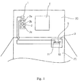
- Fig. 1 is a diagram of elements of a vehicle which is an embodiment of the present invention.
- Fig. 2 is a partial sectional view of an electrical connection box embodying the invention, accommodating a circuit, applicable in the vehicle of Fig. 1.
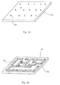
- Fig. 3 is a plan view of a circuit of Fig. 2.
- Fig. 4 is a sectional view of the circuit used in the box of Fig. 2.
- Figs. 5A to 5D show stages in a process of manufacture of the circuit of Fig. 4.
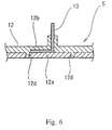
- Fig. 6 is a sectional view showing a modified form of the circuit to be used in the box of Fig. 2.
-
- As schematically shown in Fig. 1, in an automobile to which the present invention is applied, an engine E mounted in an engine room X provides drive of the vehicle and generates electrical power, e.g. through an alternator (not shown). A low-
voltage battery structure 1 and a high-voltage battery structure 2 are mounted in the engine room X, and are charged by the alternator. The low-voltage battery structure 1 consists of a general-purpose battery having a rated voltage 12V and a nominal maximum voltage of 14V. The high-voltage battery 2 consists of threebattery units batteries - The low-
voltage battery structure 1 is connected to low-voltage bus bars 10 accommodated in anelectrical connection box 3 composed of a junction box mounted in the vehicle interior Y (or, depending on the vehicle, in the engine room) to apply a low voltage (maximum voltage: 14V) to the low-voltage bus bars 10. - The high-
voltage battery structure 2 is connected to high-voltage bus bars 11 accommodated in the sameelectrical connection box 3 to apply a high voltage (maximum voltage: 42V) to the high-voltage bus bars 11. - The load side of the high-voltage bus bars 11 is connected to electrical devices or actuators to operate them electromotively. The actuators (not shown) include a power steering motor, suction and exhaust devices of the engine, and like devices consuming high power. The load side of the low-voltage bus bars 10 is connected to appliances (not shown) such as sensors, lamps, and like devices consuming relatively low power, such as are typically provided in an automobile.
- As shown in Fig. 2, the electrical connection box has a casing 3 (partially shown) of rigid molded synthetic resin in which are mounted a plurality of circuit boards hereinbelow called circuits 5 (also partially shown). Each
circuit 5 comprises a generally flat plate-like insulation body 12 comprising aplanar insulation board 12a of synthetic resin and a molded covering layer ofsynthetic resin 12b. Fixed on theboard 12a and embedded in theresin 12b are the low-voltage bus bars 10 and the high-voltage bus bars 11, which mainly lie parallel to the plane of thebody 12 and haveconnection tabs resin 12b. The bus bars 10, 11 are made of metal strips and thetabs tabs terminals 7, 8 on wires connected to therespective battery structures - Portions of the resin of the
body 12 are shown in Fig. 2 extending up the sides of thevertical tabs - Fig. 3 shows a typical example of the arrangement of the bus bars 10, 11 in the plate-like insulating
body 12. - The low-voltage bus bars 10 and the high-voltage bus bars 11 are disposed at random or freely in consideration of efficiency in designing the circuit. In other words, the low-voltage bus bars 10 are not disposed at one side of the
circuit 5 only, with the high-voltage bus bars disposed only at the other side thereof. - Therefore, the
circuit 5 includes a region A in which the low-voltage bus bars 10 are adjacent to each other, a region B in which the low-voltage bus bar 10 and the high-voltage bus bar 11 are adjacent to each other, a region C in which the high-voltage bus bars 11 are adjacent to each other. In each of the regions A, B and C, the space between the adjacent bus bars are filled with the insulating resin. - As in the case of bus bars in conventional junction boxes, the low-
voltage bus bar 10 and high-voltage bus bar 11 are bent to formtabs tabs electrical connection box 3, by fitting the terminals on thetabs voltage battery structure 1 is connected to the power supply side of the low-voltage bus bar 10, and aterminal 8 mounted at an end of another electric wire connected to the high-voltage battery structure 2 is connected to the power supply side of the high-voltage bus bar 11. - As shown in Fig. 4, the
tabs resin 12b. Portions R1 of theresin 12b overlie the flat portions of the bus bars 10, 11, and portions R2 of theresin 12b lie between the bus bars and provide insulation to prevent leak currents. The insulatingbody 12 composed of theboard 12a andresin 12b thus embeds the bus bars 10,11. - The
tabs terminals 7 and 8 are fitted on thetabs - Although the low-voltage bus bars 10 and the high-voltage bus bars 11 to which different voltages are applied are disposed in the
circuit 5, the low-voltage bus bars 10 and the high-voltage bus bars 11 are completely embedded in the resin. Thus, even though a low-voltage bus bar 10 and a high-voltage bus bar 11 are adjacent to each other, it is possible to prevent leak currents from being generated. Further, it is possible to prevent leak current from being generated between the high-voltage bus bars 11 adjacent to each other. Because thetabs insulation board 12a are embedded in the resin portions R3 from their lower ends to the position corresponding to the terminal fit-on line L, it is possible to prevent leak current from being generated between thetabs - As shown in Fig. 5, the
circuit 5 may be formed by the following procedure: - As shown in Fig. 5A, initially, the substrate or
board portion 12a of theflat insulation body 12 is formed by molding resin, withspigots 12c. - Then, as shown in Fig. 5B and 5C, the low-voltage bus bars 10 and the high-voltage bus bars 11 are located on the surface of the
board 12a, by means of thespigots 12c. - The
spigots 12c projecting from theboard 12a are inserted into holes formed in each of the bus bars 10 and 11 and deformed to fix the bus bars to theboard 12a. Theboard 12a is made of suitable resin for this purpose. Where a gap is required in the circuit of the low-voltage bus bars 10 and the high-voltage bus bars 11, they are cut. - Then, as shown in Fig. 5D, the semi-finished product of the
circuit 5 is put in a molding die. Molding resin material for thesurface resin 12b is injected into the die 30 to form theresin 12b covering the surface of the bus bars 10 and 11, the spaces between the bus bars 10 and 11, and the lower portions of thetabs tabs - The molding resin forming the
surface resin 12b has a melting temperature or a thermal deformation temperature lower than that of theboard 12a. The molding resin has a thermal coefficient of shrinkage and a thermal coefficient of expansion similar to those of theboard 12a. As shown in Fig. 6, a hole orholes 12d may be formed in theboard 12a to be filled by theresin 12b, to fix theresin 12b and theboard 12a to each other with high strength. - The
circuit 5 of these embodiments is thus applied to an automobile on which the battery of the rated voltage of 12V is mounted. But in the case where a maximum voltage of 28V is applied to a bus bar in the automobile or a larger vehicle such as a truck, the bus bar to which the voltage of 28V is applied is the low-voltage bus bar and the bus bar to which the voltage of 42V is applied is the high-voltage bus bar. The construction of thecircuit 5 and connection box in this case is the same as that of the embodiment. - In the embodiment, the maximum voltage of 42V is applied to the high-
voltage bus bar 11. But needless to say, a high voltage of 42V - 200V can be applied to the high-voltage bus bars 11, provided that safety is ensured. - The present invention therefore makes it possible to reduce the diameter of electric wires and the size of the wire harnesses in a vehicle by reducing the amount of electric current, by applying a high voltage to some circuit portions of the electrical connection box. To this end, the circuit of the electrical connection box accommodating the low-voltage bus bars and the high-voltage bus bars to which different voltages are applied is so constructed that the bus bars are completely embedded in the resin. Thus, it is possible to prevent leak currents from being generated between the low-voltage bus bar and the high-voltage bus bar.
- While the invention has been illustrated by the exemplary embodiments described above, many equivalent modifications and variations will be apparent to those skilled in the art when given this disclosure. Accordingly, the exemplary embodiments of the invention set forth above are considered to be illustrative and not limiting. Various changes to the described embodiments may be made without departing from the spirit and scope of the invention.
Claims (7)
- A vehicle havingan internal combustion engine (E) providing motive drive of the vehicle,a first, low-voltage battery structure (1) comprising at least one secondary battery, and having a nominal maximum output voltage selected from 14V and 28V,a second, high-voltage battery structure (2) comprising at least one secondary battery, and having a nominal maximum output voltage higher than that of said first battery structure (1) and not more than 200V,a plurality of electrical devices powered by said first and second battery structures, andan electrical connection box (3) containing an electrical circuit (5) therein which effects connection between said first and second battery structures (1,2) and said plurality of electrical devices,said electrical circuit (5) comprising insulation material (12; 12a,12b) in a generally plate-like shape and, embedded in said insulation material, at least one first bus bar (10) connected to said first battery structure (1) and at least one second bus bar (11) connected to said second battery structure (2), whereby in operation said first and second bus bars are at different potentials, said insulation material electrically insulating said bus bars from each other, and
wherein each of said first and second bus bars (10,11) has at least one connection tab (10a,11a) projecting out of said insulation material (12; 12a, 12b). - A vehicle according to claim 1, wherein said insulation material of said electrical circuit comprises a flat board (12a) having a surface on which said first and second bus bars (10,11) are mounted and at least one body of moulded resin material (12b) on said surface of said plate member whereby said first and second bus bars are embedded between said surface and said resin material with said tabs (10a, 11a) thereof projecting out from said resin material away from said surface.
- A vehicle according to claim 1 or 2 wherein a plurality of said low-voltage bus bars (10) and a plurality of said high-voltage bus bars (11) are freely arranged among one another in said insulation material.
- A vehicle according to claim 1, 2 or 3 wherein said insulation material embeds each said connection tab (10a, 11a) up to a location where said connection tab is attached to a terminal.
- A vehicle according to any one of claims 1 to 4 wherein said insulation material comprises a planar board (12a) on which said bus bars are fixed by means of projecting portions (12c) of material of said planar board, said projecting portions being inserted into holes of said bus bars (10, 11) and deformed to fix said bus bars to said board, said insulation material further comprising molded resin material (12) on said board.
- A vehicle according to any one of claims 1 to 5 wherein the nominal maximum output voltage of said second battery structure (2) is 42V.
- An electrical connection box adapted for use in a vehicle according to any one of claims 1 to 6,wherein each of said first and second bus bars has at least one connection tab (10a, 11a) projecting out of said insulation material.said electrical connection box (3) containing an electrical circuit (5) comprising insulation material (12; 12a, 12b) in a generally plate-like shape, and embedded in said insulation material, at least one first bus bar (10) adapted to be connected in use to said first battery structure and at least one second bus bar (11) adapted to be connected in use to said second battery structure, whereby in operation said first and second bus bars are at different potentials, and
Applications Claiming Priority (2)
| Application Number | Priority Date | Filing Date | Title |
|---|---|---|---|
| JP2000202321A JP2002027636A (en) | 2000-07-04 | 2000-07-04 | Circuits used in high-voltage electrical junction boxes |
| JP2000202321 | 2000-07-04 |
Publications (3)
| Publication Number | Publication Date |
|---|---|
| EP1174950A2 true EP1174950A2 (en) | 2002-01-23 |
| EP1174950A3 EP1174950A3 (en) | 2002-06-12 |
| EP1174950B1 EP1174950B1 (en) | 2004-09-29 |
Family
ID=18699859
Family Applications (1)
| Application Number | Title | Priority Date | Filing Date |
|---|---|---|---|
| EP01305703A Expired - Lifetime EP1174950B1 (en) | 2000-07-04 | 2001-07-02 | Electrical connection box and vehicle including it |
Country Status (4)
| Country | Link |
|---|---|
| US (1) | US6603283B2 (en) |
| EP (1) | EP1174950B1 (en) |
| JP (1) | JP2002027636A (en) |
| DE (1) | DE60105912T2 (en) |
Families Citing this family (18)
| Publication number | Priority date | Publication date | Assignee | Title |
|---|---|---|---|---|
| JP2002374075A (en) * | 2001-06-13 | 2002-12-26 | Fujitsu Ten Ltd | Wiring connection method and wiring connection structure |
| JP2003284220A (en) * | 2002-03-20 | 2003-10-03 | Yazaki Corp | Arc discharge prevention member |
| US20040264139A1 (en) * | 2003-06-24 | 2004-12-30 | Nokia Corporation | Process for manufacturing a cover |
| JP4284531B2 (en) * | 2004-07-06 | 2009-06-24 | オムロン株式会社 | Mounting board and driving device using the same |
| DE102008033483B4 (en) | 2007-07-17 | 2019-02-14 | GM Global Technology Operations LLC (n. d. Ges. d. Staates Delaware) | Interface arrangement for use with inverters of vehicles |
| US8027168B2 (en) * | 2008-08-13 | 2011-09-27 | Delphi Technologies, Inc. | Electrical center with vertical power bus bar |
| JP5332562B2 (en) * | 2008-12-03 | 2013-11-06 | 株式会社オートネットワーク技術研究所 | Circuit structure, method for manufacturing circuit structure, and electrical junction box |
| US7766673B1 (en) | 2009-07-31 | 2010-08-03 | Nissan Technical Center North America, Inc. | Fusible link busbar for starter and alternator with dual battery application |
| WO2015098569A1 (en) * | 2013-12-26 | 2015-07-02 | 矢崎総業株式会社 | Electronic-circuit unit and manufacturing method therefor |
| JP6166654B2 (en) * | 2013-12-26 | 2017-07-19 | 矢崎総業株式会社 | Molding method of exterior case in electronic circuit unit |
| JP6166655B2 (en) * | 2013-12-26 | 2017-07-19 | 矢崎総業株式会社 | Electronic circuit unit and manufacturing method thereof |
| JP6380836B2 (en) * | 2014-07-18 | 2018-08-29 | 北川工業株式会社 | Terminal block with filter |
| DE102016124963A1 (en) | 2016-12-20 | 2018-06-21 | Te Connectivity Germany Gmbh | Power transport device, in particular electrical or electromechanical busbar |
| US10608301B2 (en) | 2017-08-29 | 2020-03-31 | Nio Usa, Inc. | Power electronics with integrated busbar cooling |
| US10217693B1 (en) * | 2017-08-29 | 2019-02-26 | Nio Usa, Inc. | Methods and systems for high voltage component cooling in electric vehicle for fast charge |
| EP4002596A1 (en) * | 2020-11-20 | 2022-05-25 | Aptiv Technologies Limited | Electrical connector |
| WO2023007571A1 (en) | 2021-07-27 | 2023-02-02 | 三菱電機株式会社 | Wiring component for electric device |
| EP4423846A4 (en) * | 2021-10-27 | 2025-09-03 | Atieva Inc | Overmolded busbars and integrated sensors |
Family Cites Families (12)
| Publication number | Priority date | Publication date | Assignee | Title |
|---|---|---|---|---|
| US4781600A (en) * | 1986-06-25 | 1988-11-01 | Yazaki Corporation | Junction box and a process of assembling the same |
| JPH0649062Y2 (en) | 1987-04-07 | 1994-12-12 | 矢崎総業株式会社 | Waterproof wiring junction box |
| JPH0615457Y2 (en) * | 1988-07-15 | 1994-04-20 | 矢崎総業株式会社 | Electrical junction box |
| JP3163592B2 (en) * | 1993-04-01 | 2001-05-08 | 矢崎総業株式会社 | Composite circuit board |
| US5430619A (en) * | 1994-03-18 | 1995-07-04 | Lindenbaum Systems Design, Inc. | Terminal box |
| US6008982A (en) * | 1998-05-20 | 1999-12-28 | General Motors Corporation | Low profile electrical distribution center and method of making a bus subassembly therefor |
| JP3434710B2 (en) * | 1998-10-06 | 2003-08-11 | 矢崎総業株式会社 | Heat dissipation structure of electrical junction box |
| JP2000324857A (en) * | 1999-03-11 | 2000-11-24 | Toyota Motor Corp | Multi-type power supply device, equipment and motor drive device equipped with this power supply device, and hybrid vehicle |
| JP2002084624A (en) * | 2000-09-05 | 2002-03-22 | Sumitomo Wiring Syst Ltd | Electrical junction box for high voltage |
| JP2002112435A (en) * | 2000-09-27 | 2002-04-12 | Sumitomo Wiring Syst Ltd | Electrical junction box for high voltage |
| JP3680733B2 (en) * | 2000-12-28 | 2005-08-10 | 住友電装株式会社 | Electrical junction box |
| JP3724372B2 (en) * | 2000-12-28 | 2005-12-07 | 住友電装株式会社 | Electrical junction box |
-
2000
- 2000-07-04 JP JP2000202321A patent/JP2002027636A/en active Pending
-
2001
- 2001-07-02 DE DE60105912T patent/DE60105912T2/en not_active Expired - Lifetime
- 2001-07-02 EP EP01305703A patent/EP1174950B1/en not_active Expired - Lifetime
- 2001-07-05 US US09/897,903 patent/US6603283B2/en not_active Expired - Fee Related
Non-Patent Citations (1)
| Title |
|---|
| None |
Also Published As
| Publication number | Publication date |
|---|---|
| EP1174950B1 (en) | 2004-09-29 |
| JP2002027636A (en) | 2002-01-25 |
| US6603283B2 (en) | 2003-08-05 |
| EP1174950A3 (en) | 2002-06-12 |
| US20020002961A1 (en) | 2002-01-10 |
| DE60105912T2 (en) | 2006-03-02 |
| DE60105912D1 (en) | 2004-11-04 |
Similar Documents
| Publication | Publication Date | Title |
|---|---|---|
| US6603283B2 (en) | Vehicle having an electrical connection box and electrical connection box for use in the vehicle | |
| US6478585B2 (en) | Electrical connection box for a vehicle | |
| JP5074744B2 (en) | Electrical junction box | |
| US6506061B2 (en) | Electrical connection box to be mounted on a vehicle | |
| CN102403683B (en) | Connector cover and junction box unit provided with same | |
| US6629850B2 (en) | Electrical connection box for a vehicle | |
| WO2011126140A1 (en) | Fuse unit | |
| JP2008199840A (en) | Electrical junction box | |
| US6443748B1 (en) | Electrical connection box for a vehicle | |
| US7053298B2 (en) | Electric connecting box | |
| US20090091183A1 (en) | Modular Power Distribution Assembly and Method of Making Same | |
| US6650087B2 (en) | Vehicle having an electrical connection box and electrical connection box for use in the vehicle | |
| US6922331B2 (en) | Bus bar structure of electric distribution box | |
| US6542064B2 (en) | Fuse | |
| EP1172901B1 (en) | Vehicle having an electrical connection box and electrical connection box for use in the vehicle | |
| JP2004119187A (en) | Battery configuration method | |
| JP2010004643A (en) | Electric connection box | |
| JP2002034120A (en) | Circuits used in high-voltage electrical junction boxes | |
| JP3916283B2 (en) | Junction box | |
| JP2002034121A (en) | Circuits used in high-voltage electrical junction boxes | |
| WO2021006109A1 (en) | Electrical junction box | |
| KR100576742B1 (en) | Junction box power supply structure | |
| WO2022138220A1 (en) | Electrical junction box | |
| KR20250059225A (en) | Electronic device | |
| JP2001319557A (en) | Fuse box |
Legal Events
| Date | Code | Title | Description |
|---|---|---|---|
| PUAI | Public reference made under article 153(3) epc to a published international application that has entered the european phase |
Free format text: ORIGINAL CODE: 0009012 |
|
| 17P | Request for examination filed |
Effective date: 20010723 |
|
| AK | Designated contracting states |
Kind code of ref document: A2 Designated state(s): AT BE CH CY DE DK ES FI FR GB GR IE IT LI LU MC NL PT SE TR |
|
| AX | Request for extension of the european patent |
Free format text: AL;LT;LV;MK;RO;SI |
|
| PUAL | Search report despatched |
Free format text: ORIGINAL CODE: 0009013 |
|
| AK | Designated contracting states |
Kind code of ref document: A3 Designated state(s): AT BE CH CY DE DK ES FI FR GB GR IE IT LI LU MC NL PT SE TR |
|
| AX | Request for extension of the european patent |
Free format text: AL;LT;LV;MK;RO;SI |
|
| RIC1 | Information provided on ipc code assigned before grant |
Free format text: 7H 01R 9/22 A, 7H 01R 9/24 B, 7B 60R 16/02 B |
|
| AKX | Designation fees paid |
Designated state(s): DE FR GB |
|
| 17Q | First examination report despatched |
Effective date: 20030214 |
|
| GRAP | Despatch of communication of intention to grant a patent |
Free format text: ORIGINAL CODE: EPIDOSNIGR1 |
|
| GRAS | Grant fee paid |
Free format text: ORIGINAL CODE: EPIDOSNIGR3 |
|
| GRAA | (expected) grant |
Free format text: ORIGINAL CODE: 0009210 |
|
| AK | Designated contracting states |
Kind code of ref document: B1 Designated state(s): DE FR GB |
|
| REG | Reference to a national code |
Ref country code: GB Ref legal event code: FG4D |
|
| REG | Reference to a national code |
Ref country code: IE Ref legal event code: FG4D |
|
| REF | Corresponds to: |
Ref document number: 60105912 Country of ref document: DE Date of ref document: 20041104 Kind code of ref document: P |
|
| ET | Fr: translation filed | ||
| PLBE | No opposition filed within time limit |
Free format text: ORIGINAL CODE: 0009261 |
|
| STAA | Information on the status of an ep patent application or granted ep patent |
Free format text: STATUS: NO OPPOSITION FILED WITHIN TIME LIMIT |
|
| 26N | No opposition filed |
Effective date: 20050630 |
|
| PGFP | Annual fee paid to national office [announced via postgrant information from national office to epo] |
Ref country code: GB Payment date: 20060628 Year of fee payment: 6 |
|
| PGFP | Annual fee paid to national office [announced via postgrant information from national office to epo] |
Ref country code: FR Payment date: 20060719 Year of fee payment: 6 |
|
| GBPC | Gb: european patent ceased through non-payment of renewal fee |
Effective date: 20070702 |
|
| PG25 | Lapsed in a contracting state [announced via postgrant information from national office to epo] |
Ref country code: GB Free format text: LAPSE BECAUSE OF NON-PAYMENT OF DUE FEES Effective date: 20070702 |
|
| REG | Reference to a national code |
Ref country code: FR Ref legal event code: ST Effective date: 20080331 |
|
| PG25 | Lapsed in a contracting state [announced via postgrant information from national office to epo] |
Ref country code: FR Free format text: LAPSE BECAUSE OF NON-PAYMENT OF DUE FEES Effective date: 20070731 |
|
| PGFP | Annual fee paid to national office [announced via postgrant information from national office to epo] |
Ref country code: DE Payment date: 20120627 Year of fee payment: 12 |
|
| REG | Reference to a national code |
Ref country code: DE Ref legal event code: R119 Ref document number: 60105912 Country of ref document: DE Effective date: 20140201 |
|
| PG25 | Lapsed in a contracting state [announced via postgrant information from national office to epo] |
Ref country code: DE Free format text: LAPSE BECAUSE OF NON-PAYMENT OF DUE FEES Effective date: 20140201 |