EP1174949A1 - A shielding terminal and a mounting method therefore - Google Patents
A shielding terminal and a mounting method therefore Download PDFInfo
- Publication number
- EP1174949A1 EP1174949A1 EP01113693A EP01113693A EP1174949A1 EP 1174949 A1 EP1174949 A1 EP 1174949A1 EP 01113693 A EP01113693 A EP 01113693A EP 01113693 A EP01113693 A EP 01113693A EP 1174949 A1 EP1174949 A1 EP 1174949A1
- Authority
- EP
- European Patent Office
- Prior art keywords
- terminal
- locking member
- locking
- shielded cable
- shielding
- Prior art date
- Legal status (The legal status is an assumption and is not a legal conclusion. Google has not performed a legal analysis and makes no representation as to the accuracy of the status listed.)
- Granted
Links
- 238000000034 method Methods 0.000 title claims description 9
- 238000002788 crimping Methods 0.000 claims abstract description 27
- 230000013011 mating Effects 0.000 description 5
- 238000005452 bending Methods 0.000 description 4
- 239000002184 metal Substances 0.000 description 3
- 238000010276 construction Methods 0.000 description 2
- 229920003002 synthetic resin Polymers 0.000 description 2
- 239000000057 synthetic resin Substances 0.000 description 2
- 230000001419 dependent effect Effects 0.000 description 1
- 238000003780 insertion Methods 0.000 description 1
- 230000037431 insertion Effects 0.000 description 1
- 239000011810 insulating material Substances 0.000 description 1
- 239000000463 material Substances 0.000 description 1
- 239000003381 stabilizer Substances 0.000 description 1
Images


Classifications
-
- H—ELECTRICITY
- H01—ELECTRIC ELEMENTS
- H01R—ELECTRICALLY-CONDUCTIVE CONNECTIONS; STRUCTURAL ASSOCIATIONS OF A PLURALITY OF MUTUALLY-INSULATED ELECTRICAL CONNECTING ELEMENTS; COUPLING DEVICES; CURRENT COLLECTORS
- H01R9/00—Structural associations of a plurality of mutually-insulated electrical connecting elements, e.g. terminal strips or terminal blocks; Terminals or binding posts mounted upon a base or in a case; Bases therefor
- H01R9/03—Connectors arranged to contact a plurality of the conductors of a multiconductor cable, e.g. tapping connections
- H01R9/05—Connectors arranged to contact a plurality of the conductors of a multiconductor cable, e.g. tapping connections for coaxial cables
- H01R9/0518—Connection to outer conductor by crimping or by crimping ferrule
-
- H—ELECTRICITY
- H01—ELECTRIC ELEMENTS
- H01R—ELECTRICALLY-CONDUCTIVE CONNECTIONS; STRUCTURAL ASSOCIATIONS OF A PLURALITY OF MUTUALLY-INSULATED ELECTRICAL CONNECTING ELEMENTS; COUPLING DEVICES; CURRENT COLLECTORS
- H01R13/00—Details of coupling devices of the kinds covered by groups H01R12/70 or H01R24/00 - H01R33/00
- H01R13/40—Securing contact members in or to a base or case; Insulating of contact members
- H01R13/42—Securing in a demountable manner
- H01R13/436—Securing a plurality of contact members by one locking piece or operation
- H01R13/4361—Insertion of locking piece perpendicular to direction of contact insertion
Definitions
- the present invention relates to a shielding terminal to be connected with an end of a shielded cable and to a mounting method therefor.
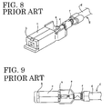
- a shielding terminal shown in FIGS. 8 and 9 is known as a shielding terminal of this type.
- This terminal is provided with an inner terminal "a” to be connected with a mating terminal and an outer terminal “c” accommodating the inner terminal "a” with a dielectric element "b” provided therebetween.
- the inner terminal "a” is crimped into connection with an end of a core "e” of a shielded cable “d”
- the outer terminal "c” is crimped into connection with ends of a braided wire "f” and a sheath "g".
- Such a construction is disclosed in Japanese Unexamined Utility Model Publication No. 5-27983 and other publications.
- the present invention was developed in view of the above situation and an object thereof is to provide a shielding terminal and a mounting method allowing for a larger fastening force of the shielding terminal to a shielded cable.
- a shielding terminal to be connected with an end of a shielded cable, comprising:
- a shielding terminal to be connected with an end of a shielded cable formed by concentrically arranging a core and a braided wire with an insulating layer provided therebetween and covering the outer surface of the braided wire by a sheath, comprising:
- an opening is formed in part of a circumferential surface of the outer terminal, the locking member at least partly being mounted or mountable in the opening.
- the locking member Since the locking member is mounted in the opening formed in the circumferential surface of the outer terminal, it prevents the shielding terminal from becoming larger.
- a shield plate is mounted on or provided in the locking member, the shield plate being preferably connectable with the shield layer and/or the outer terminal.
- a shielding performance can be improved by providing the shield plate in the opening where no shield member has been present.
- the locking member is formed with a locking edge being engageable for locking with a rear portion of the inner terminal, preferably of a connection portion thereof.
- the locking member comprises latching means for latching the locking member with the inner and/or outer terminals.
- the latching means comprise hooking portions engageable with at least one crimping portion of the outer terminal.
- the locking member comprises a locking means for coming into engagement with a sheath of the shielded cable and/or with the dielectric member.
- a method of mounting or assembling or connecting a shielding terminal, in particular according to the invention or an embodiment thereof, with an end of a shield cable comprising the following steps:
- the locking member is mounted in an opening formed in part of a circumferential surface of the outer terminal.
- a shield plate is mounted on or provided in the locking member, the shield plate being preferably connected with the shield layer and/or the outer terminal.
- a female shielding terminal 10 which is used by being crimped or folded or bent into connection with an end of a shielded cable 1.
- the shielded cable 1 has a known structure, i.e. a core 2 e.g. formed by bundling a plurality of strands, an insulating layer 3, a shield layer such as a braided wire 4 or a shield film (not shown) and a sheath 5 e.g. made of a rubber or the like are concentrically arranged in this order from the innermost side as shown in FIGS. 1 and 2.
- an end of the shielded cable 1 is processed by stripping an end of the sheath 5 off, at least partly folding the thus exposed section of the braided wire 4 substantially back on the sheath 5, and cutting an exposed end of the insulating layer 3 off to at least partly expose the core 2.
- the shielding terminal 10 is comprised of an inner terminal 11, an outer terminal 12, a dielectric element 13 and a locking member 14 as shown in FIGS. 1 and 2.
- the inner terminal 11 is formed into a female terminal e.g. by bending a metallic plate, a connecting portion 15 preferably in the form of a substantially rectangular tube is formed at its leading end side, and a pair of transversely arranged inner crimping pieces 16 to be crimped or folded or bent into connection with the core 2 of the shielded cable 1 are formed behind or adjacent to the connecting portion 15.
- a preferably pair of left and right resilient or elastic contact pieces 17 to be connected with a tab (not shown) of a mating male inner terminal are formed at the left and right side surfaces of the connecting portion 15.
- the preferably two elastic contact pieces 17 cantilever forward and are bent so that the facing surfaces thereof at the leading end bulge out inwardly. They are resiliently or elastically deformable in such directions that their leading ends move toward and away from each other, and the tab of the mating terminal is insertable therebetween.
- the bottom wall of the rear end of the connecting portion 15 is cut off, and one or more biting blades or tooth or projections 18 are formed at the bottom edges of the left and side walls of this rear end.
- these biting blades 18 bite in the bottom wall thereof.
- the outer terminal 12 is likewise formed e.g. by bending a metallic plate and is comprised of an accommodating portion 20 in the form of a large substantially rectangular tube, a covering wall portion 21 whose walls are substantially closed except the bottom wall, and an outer crimping portion 23 to be crimped or folded or bent into connection with a folded section of the braided wire 4 of the shielded cable 1.
- the portions 20, 21, 23 are formed in this order from the leading end side.
- the outer crimping portion 23 is provided with a pair of transversely arranged outer crimping pieces 24, which are at least partly wound or folded on or around the folded section of the braided wire 4 preferably such that an end of one crimping piece 24 is placed substantially over that of the other.
- the crimped outer crimping portion 23 has an upper surface which is an arcuate surface having a small curvature, a bottom surface which is substantially semicircular, and left and right surfaces substantially parallel to each other.
- Wedge-shaped projections 25 are formed at the base ends of the two outer crimping pieces 24 and on the outer crimping piece 24 which is placed more inside the other in its wound state. Further, stabilizers 26 project laterally outward from the bottom edges of the left and right side walls of the covering wall portion 21.
- the dielectric element 13 is made of an insulating material such as a synthetic resin, and acts to electrically insulate the inner and outer terminals 11, 12 from each other.
- the dielectric element 13 has a shape mating or conforming to the inner and outer terminals 11, 12 and preferably is in the form of a substantially rectangular tube having a thick wall and fittable into the front end of the accommodating portion 20 of the outer terminal 12, and an accommodating hole 28 into which the connecting portion 15 of the inner terminal 11 is to be at least partly accommodated is defined inside the dielectric element 13.
- a flange 29 to be brought into abutment against the front edge of the accommodating portion 20 of the outer terminal 12 is formed at the front surface of the dielectric element 13, and a terminal insertion opening 30 into which the tab of the mating terminal is to be inserted is defined at the front end of the accommodating hole 28. Further, a lower half of the rear end of the dielectric element 13 is cut off so as to conform to the configuration of the accommodating portion 20 of the outer terminal 12.
- a metal locking portion 32 is formed in the upper surface of the accommodating portion 20 of the outer terminal 12 preferably by making a cut in the upper surface and bending a cut portion inward in such a manner as to extend obliquely backward, whereas a locking hole 33 into which the metal locking portion 32 of the outer terminal 12 is fittable is formed in the upper surface of the dielectric element 13.
- the locking member 14 is made e.g. of a synthetic resin material and mounted in an area substantially extending from an opening 22 of the covering wall portion 21 of the outer terminal 12 to the outer crimping portion 23.
- the locking member 14 includes a base plate 40 which is substantially narrow in forward and backward or longitudinal directions and whose front portion is so narrowed as to be substantially closely fitted or fittable into the opening 22 of the covering wall portion 21 (see FIG. 7).
- a pair of mounting plates 41 project at angle different from 0° or 180°, preferably substantially normal to or stand up from the opposite side edges of the rear end of the base plate 40.
- the mounting plates 41 are so formed as to substantially surround the crimped outer crimping portion 23 from its bottom surface to its left and right side surfaces, and hooking portions 42 engageable with the left and right corners of the upper surface of the crimped outer crimping portion 23 are formed at the upper ends of the mounting plates 41 preferably by bending.
- the mounting plates 41 are resiliently or elastically deformable such that their upper ends move toward and away from each other.
- a front end portion of the base plate 40 is formed to be thicker than a rear end portion, and the rear end of the upper surface of this front end portion is stepped to form a stepped portion which serves as a locking step 44 for coming into engagement with the end (covered by the folded section of the braided wire 4) of the sheath 5 of the shielded cable 1 and the front part of the crimped outer crimping portion 23.
- a front half of the front end portion of the base plate 40 is substantially thinned in the widthwise center of its lower surface to form a gate portion.
- the upper edge of the front surface of this gate portion serves as a locking edge 45 engageable with the bottom end of the rear end of the connecting portion 15 of the inner terminal 11.
- left and right side edges 46 of the front surface of the gate portion are engageable with the edges of the lower surfaces of the dielectric element 13 and the accommodating portion 20 of the outer terminal 12 which edges are left by cutting off the portions of the dielectric element 13 and the accommodating portion 20.
- a pair of left and right side walls 48 stand from the left and right side edges of the front end portion of the base plate 40, and a portion of an assembly of the inner terminal 11 and the shielded cable 1 from the end of the insulating layer 3 to the inner crimping pieces 16 can be at least partly accommodated between the two side walls 48.
- the shielding terminal 10 is connected with the end of the shielded cable 1 in a following procedure.
- the end of the shielded cable 1 is processed as described above.
- the inner crimping pieces 16 of the inner terminal 11 are crimped or folded or bent into connection with the end of the core 2.
- the dielectric element 13 is at least partly inserted into the accommodating portion 20 of the outer terminal 12 preferably from front.
- the dielectric element 13 is pushed in while resiliently or elastically deforming the metal locking portion 32, which is elastically restored preferably substantially to its original shape to fit into the locking hole 33 when the flange 29 comes into contact with the front edge of the accommodating portion 20 as shown in FIG. 4, with the result that the dielectric element 13 is fixed at the front end of the accommodating portion 20.
- the inner terminal 11 is at least partly inserted into the accommodating portion 20 of the outer terminal 12 from behind, and is pushed into the accommodating hole 28 of the dielectric element 13 fixed in the accommodating portion 20 by catching the inner terminal 11 using a jig inserted through the opening 22 of the covering wall portion 21.
- the biting blades 18 are pressed against the bottom wall of the accommodating hole 28 to bite therein. As a result, the inner terminal 11 is partly locked.
- the outer crimping pieces 24 of the outer terminal 12 are crimped and at least partly wound around or on the folded section of the braided wire 4, thereby being fastened to the folded section of the braided wire 4 and the end of the sheath 5. At this time, the outer crimping pieces 24 are more strongly fastened by the projections 25 biting in the braided wire 4.
- the locking member 14 is mounted in the area extending from the opening 22 of the covering wall portion 21 of the outer terminal 12 to the outer crimping portion 23. More specifically, when the opposite side walls 48 on the base plate 40 are inserted into the opening 22 of the covering wall portion 21, the opposite mounting plates 41 are moved along the crimped outer crimping portion 23 while widening a spacing therebetween.
- the locking step 44 is engaged with the end of the sheath 5 and the front part of the outer crimping portion 23; the rear edges of the side walls 48 are engaged with the front end of the sheath 5; the left and right side edges 46 at the front surface of the gate portion are engaged with the cut-off portions of the dielectric element 13 and the outer terminal 12 from behind; and/or the front ends of the side walls 48 are engaged with the rear end of the upper part of the dielectric element 13.
- the locking member 14 is fixed in the outer terminal 12 so as not to come out downward and move forward and backward while covering the opening 22 of the covering wall portion 21 of the outer terminal 12 and the outer crimping portion 23.
- the locking edge 45 at the leading end of the locking member 14 faces the bottom end of the rear end of the connecting portion 15 of the inner terminal 11 so as to be engageable therewith for locking.
- a so-called “double-locking construction” is realized by providing the locking member 14 for locking the inner terminal 11 in the outer terminal 12. This effectively prevents the inner terminal 11 from coming out of the dielectric element 13 and strengthens a fastening force to the shielded cable 1.
- the locking member 14 is mounted mainly by being fitted in the opening 22 of the covering wall portion 21, it prevents the entire shielding terminal 10 from becoming larger despite additional provision of the locking member 14.
Landscapes
- Details Of Connecting Devices For Male And Female Coupling (AREA)
- Coupling Device And Connection With Printed Circuit (AREA)
Abstract
Description
- The present invention relates to a shielding terminal to be connected with an end of a shielded cable and to a mounting method therefor.
- A shielding terminal shown in FIGS. 8 and 9 is known as a shielding terminal of this type. This terminal is provided with an inner terminal "a" to be connected with a mating terminal and an outer terminal "c" accommodating the inner terminal "a" with a dielectric element "b" provided therebetween. The inner terminal "a" is crimped into connection with an end of a core "e" of a shielded cable "d", and the outer terminal "c" is crimped into connection with ends of a braided wire "f" and a sheath "g". Such a construction is disclosed in Japanese Unexamined Utility Model Publication No. 5-27983 and other publications.
- It is one of essential points for the shielding terminal of this type to have a large fastening force to the shielded cable "d" in order to prevent the shielded cable "d" from being detached from the shielded terminal when a pulling force acts on the shielded cable "d". Conventionally, biting blades have been formed to project from the outer surface of the inner terminal "a" to prevent such a detachment by causing the biting blades to bite in the inner surface of the dielectric element "b".
- However, in the conventional shielding terminal, a groove is formed behind the biting blades biting in the inner surface, and no sufficient force to prevent the detachment can be obtained due to a possibly insufficient degree of engagement. Thus, there is a demand for a further improvement.
- The present invention was developed in view of the above situation and an object thereof is to provide a shielding terminal and a mounting method allowing for a larger fastening force of the shielding terminal to a shielded cable.
- This object is solved according to the invention by a shielding terminal according to
claim 1 and by a method for mounting a shielding terminal according to claim 8. Preferred embodiments of the invention are subject of the dependent claims. - According to the invention, there is provided a shielding terminal to be connected with an end of a shielded cable, comprising:
- an inner terminal to be connected with a core of the shielded cable,
- an outer terminal to be connected with a shield layer of the shielded cable while at least partly accommodating the inner terminal with a dielectric element provided between the inner and outer terminals, and
- a locking member mountable in or on the outer terminal for locking the inner terminal so as not to come out.
-
- Even if a force acts to move the inner terminal to come out of the dielectric element such as when the core is pulled, the inner terminal is locked by the locking member mounted in the outer terminal, thereby being effectively prevented from coming out of the dielectric element. Therefore, a fastening force to the shielded cable can be strengthened.
- According to a preferred embodiment of the invention, there is provided a shielding terminal to be connected with an end of a shielded cable formed by concentrically arranging a core and a braided wire with an insulating layer provided therebetween and covering the outer surface of the braided wire by a sheath, comprising:
- an inner terminal to be connected with the core,
- an outer terminal to be connected with the braided wire while accommodating the inner terminal with a dielectric element provided between the inner and outer terminals, and
- a locking member mounted in the outer terminal for locking the inner terminal so as not to come out.
-
- Preferably, an opening is formed in part of a circumferential surface of the outer terminal, the locking member at least partly being mounted or mountable in the opening.
- Since the locking member is mounted in the opening formed in the circumferential surface of the outer terminal, it prevents the shielding terminal from becoming larger.
- Further preferably, a shield plate is mounted on or provided in the locking member, the shield plate being preferably connectable with the shield layer and/or the outer terminal.
- A shielding performance can be improved by providing the shield plate in the opening where no shield member has been present.
- Further preferably, the locking member is formed with a locking edge being engageable for locking with a rear portion of the inner terminal, preferably of a connection portion thereof.
- Still further preferably, the locking member comprises latching means for latching the locking member with the inner and/or outer terminals.
- Further preferably, the latching means comprise hooking portions engageable with at least one crimping portion of the outer terminal.
- Most preferably, the locking member comprises a locking means for coming into engagement with a sheath of the shielded cable and/or with the dielectric member.
- According to the invention, there is further provided a method of mounting or assembling or connecting a shielding terminal, in particular according to the invention or an embodiment thereof, with an end of a shield cable, comprising the following steps:
- connecting an inner terminal with a core of the shielded cable,
- connecting an outer terminal with a shield layer of the shielded cable while at least partly accommodating the inner terminal with a dielectric element provided between the inner and outer terminals, and
- mounting a locking member in or on the outer terminal for locking the inner terminal so as not to come out.
-
- According to a further preferred embodiment of the invention, the locking member is mounted in an opening formed in part of a circumferential surface of the outer terminal.
- Preferably, a shield plate is mounted on or provided in the locking member, the shield plate being preferably connected with the shield layer and/or the outer terminal.
- These and other objects, features and advantages of the present invention will become apparent upon reading of the following detailed description of preferred embodiments and accompanying drawings in which:
- FIG. 1 is an exploded perspective view of one embodiment of the present invention,
- FIG. 2 is an exploded side view partly in section of this embodiment,
- FIG. 3 is a front view of a locking member,
- FIG. 4 is a vertical section showing a mounting operation of the locking member,
- FIG. 5 is a vertical section showing an assembled state of a shielding terminal and a shielded cable,
- FIG. 6 is a rear view showing the assembled state,
- FIG. 7 is a bottom view showing the assembled state, and
- FIGS. 8 and 9 are a perspective view and a plan view of a prior art shielding terminal connected with a shielded cable.
-
- Hereinafter, one embodiment of the present invention is described with reference to FIGS. 1 to 7.
- In this embodiment is shown a
female shielding terminal 10, which is used by being crimped or folded or bent into connection with an end of a shieldedcable 1. - The shielded
cable 1 has a known structure, i.e. acore 2 e.g. formed by bundling a plurality of strands, aninsulating layer 3, a shield layer such as abraided wire 4 or a shield film (not shown) and asheath 5 e.g. made of a rubber or the like are concentrically arranged in this order from the innermost side as shown in FIGS. 1 and 2. In this embodiment, an end of the shieldedcable 1 is processed by stripping an end of thesheath 5 off, at least partly folding the thus exposed section of the braidedwire 4 substantially back on thesheath 5, and cutting an exposed end of the insulatinglayer 3 off to at least partly expose thecore 2. - The
shielding terminal 10 is comprised of aninner terminal 11, anouter terminal 12, adielectric element 13 and alocking member 14 as shown in FIGS. 1 and 2. - The
inner terminal 11 is formed into a female terminal e.g. by bending a metallic plate, a connectingportion 15 preferably in the form of a substantially rectangular tube is formed at its leading end side, and a pair of transversely arrangedinner crimping pieces 16 to be crimped or folded or bent into connection with thecore 2 of the shieldedcable 1 are formed behind or adjacent to the connectingportion 15. A preferably pair of left and right resilient orelastic contact pieces 17 to be connected with a tab (not shown) of a mating male inner terminal are formed at the left and right side surfaces of the connectingportion 15. The preferably twoelastic contact pieces 17 cantilever forward and are bent so that the facing surfaces thereof at the leading end bulge out inwardly. They are resiliently or elastically deformable in such directions that their leading ends move toward and away from each other, and the tab of the mating terminal is insertable therebetween. - The bottom wall of the rear end of the connecting
portion 15 is cut off, and one or more biting blades or tooth orprojections 18 are formed at the bottom edges of the left and side walls of this rear end. When thedielectric element 13 is at least partly pressed in, thesebiting blades 18 bite in the bottom wall thereof. - The
outer terminal 12 is likewise formed e.g. by bending a metallic plate and is comprised of anaccommodating portion 20 in the form of a large substantially rectangular tube, acovering wall portion 21 whose walls are substantially closed except the bottom wall, and anouter crimping portion 23 to be crimped or folded or bent into connection with a folded section of thebraided wire 4 of the shieldedcable 1. Theportions outer crimping portion 23 is provided with a pair of transversely arrangedouter crimping pieces 24, which are at least partly wound or folded on or around the folded section of the braidedwire 4 preferably such that an end of one crimpingpiece 24 is placed substantially over that of the other. The crimpedouter crimping portion 23 has an upper surface which is an arcuate surface having a small curvature, a bottom surface which is substantially semicircular, and left and right surfaces substantially parallel to each other. - Wedge-
shaped projections 25 are formed at the base ends of the twoouter crimping pieces 24 and on theouter crimping piece 24 which is placed more inside the other in its wound state. Further,stabilizers 26 project laterally outward from the bottom edges of the left and right side walls of thecovering wall portion 21. - The
dielectric element 13 is made of an insulating material such as a synthetic resin, and acts to electrically insulate the inner andouter terminals dielectric element 13 has a shape mating or conforming to the inner andouter terminals accommodating portion 20 of theouter terminal 12, and anaccommodating hole 28 into which the connectingportion 15 of theinner terminal 11 is to be at least partly accommodated is defined inside thedielectric element 13. Aflange 29 to be brought into abutment against the front edge of theaccommodating portion 20 of theouter terminal 12 is formed at the front surface of thedielectric element 13, and a terminal insertion opening 30 into which the tab of the mating terminal is to be inserted is defined at the front end of theaccommodating hole 28. Further, a lower half of the rear end of thedielectric element 13 is cut off so as to conform to the configuration of theaccommodating portion 20 of theouter terminal 12. - A
metal locking portion 32 is formed in the upper surface of theaccommodating portion 20 of theouter terminal 12 preferably by making a cut in the upper surface and bending a cut portion inward in such a manner as to extend obliquely backward, whereas alocking hole 33 into which themetal locking portion 32 of theouter terminal 12 is fittable is formed in the upper surface of thedielectric element 13. - The locking
member 14 is made e.g. of a synthetic resin material and mounted in an area substantially extending from anopening 22 of the coveringwall portion 21 of theouter terminal 12 to the outer crimpingportion 23. The lockingmember 14 includes abase plate 40 which is substantially narrow in forward and backward or longitudinal directions and whose front portion is so narrowed as to be substantially closely fitted or fittable into theopening 22 of the covering wall portion 21 (see FIG. 7). A pair of mountingplates 41 project at angle different from 0° or 180°, preferably substantially normal to or stand up from the opposite side edges of the rear end of thebase plate 40. The mountingplates 41 are so formed as to substantially surround the crimped outer crimpingportion 23 from its bottom surface to its left and right side surfaces, and hookingportions 42 engageable with the left and right corners of the upper surface of the crimped outer crimpingportion 23 are formed at the upper ends of the mountingplates 41 preferably by bending. The mountingplates 41 are resiliently or elastically deformable such that their upper ends move toward and away from each other. - On the other hand, a front end portion of the
base plate 40 is formed to be thicker than a rear end portion, and the rear end of the upper surface of this front end portion is stepped to form a stepped portion which serves as a lockingstep 44 for coming into engagement with the end (covered by the folded section of the braided wire 4) of thesheath 5 of the shieldedcable 1 and the front part of the crimped outer crimpingportion 23. - A front half of the front end portion of the
base plate 40 is substantially thinned in the widthwise center of its lower surface to form a gate portion. The upper edge of the front surface of this gate portion serves as a lockingedge 45 engageable with the bottom end of the rear end of the connectingportion 15 of theinner terminal 11. Further, left and right side edges 46 of the front surface of the gate portion are engageable with the edges of the lower surfaces of thedielectric element 13 and theaccommodating portion 20 of theouter terminal 12 which edges are left by cutting off the portions of thedielectric element 13 and theaccommodating portion 20. - A pair of left and
right side walls 48 stand from the left and right side edges of the front end portion of thebase plate 40, and a portion of an assembly of theinner terminal 11 and the shieldedcable 1 from the end of the insulatinglayer 3 to the inner crimpingpieces 16 can be at least partly accommodated between the twoside walls 48. - Next, the function of this embodiment is described. The shielding
terminal 10 is connected with the end of the shieldedcable 1 in a following procedure. - The end of the shielded
cable 1 is processed as described above. First, the inner crimpingpieces 16 of theinner terminal 11 are crimped or folded or bent into connection with the end of thecore 2. Then, thedielectric element 13 is at least partly inserted into theaccommodating portion 20 of theouter terminal 12 preferably from front. Thedielectric element 13 is pushed in while resiliently or elastically deforming themetal locking portion 32, which is elastically restored preferably substantially to its original shape to fit into the lockinghole 33 when theflange 29 comes into contact with the front edge of theaccommodating portion 20 as shown in FIG. 4, with the result that thedielectric element 13 is fixed at the front end of theaccommodating portion 20. - Subsequently, the
inner terminal 11 is at least partly inserted into theaccommodating portion 20 of the outer terminal 12 from behind, and is pushed into theaccommodating hole 28 of thedielectric element 13 fixed in theaccommodating portion 20 by catching theinner terminal 11 using a jig inserted through theopening 22 of the coveringwall portion 21. At this stage, the bitingblades 18 are pressed against the bottom wall of theaccommodating hole 28 to bite therein. As a result, theinner terminal 11 is partly locked. - Then, the outer crimping
pieces 24 of theouter terminal 12 are crimped and at least partly wound around or on the folded section of thebraided wire 4, thereby being fastened to the folded section of thebraided wire 4 and the end of thesheath 5. At this time, the outer crimpingpieces 24 are more strongly fastened by theprojections 25 biting in thebraided wire 4. - Finally, as indicated by an arrow of FIG. 4, the locking
member 14 is mounted in the area extending from theopening 22 of the coveringwall portion 21 of theouter terminal 12 to the outer crimpingportion 23. More specifically, when theopposite side walls 48 on thebase plate 40 are inserted into theopening 22 of the coveringwall portion 21, the opposite mountingplates 41 are moved along the crimped outer crimpingportion 23 while widening a spacing therebetween. When theside walls 48 are inserted to such a degree as to come into contact with the ceiling surface of theaccommodating portion 20 of theouter terminal 12, the hookingportions 42 of the mountingplates 41 pass the corners of the upper surface of the outer crimpingportion 23, whereby the hookingportions 42 are engaged with the corners of the upper surface of the outer crimpingportion 23 while the mountingplates 41 are restored as shown in FIG. 6. Preferably simultaneously, the lockingstep 44 is engaged with the end of thesheath 5 and the front part of the outer crimpingportion 23; the rear edges of theside walls 48 are engaged with the front end of thesheath 5; the left and right side edges 46 at the front surface of the gate portion are engaged with the cut-off portions of thedielectric element 13 and the outer terminal 12 from behind; and/or the front ends of theside walls 48 are engaged with the rear end of the upper part of thedielectric element 13. - In this way, the locking
member 14 is fixed in theouter terminal 12 so as not to come out downward and move forward and backward while covering theopening 22 of the coveringwall portion 21 of theouter terminal 12 and the outer crimpingportion 23. - At this time, the locking
edge 45 at the leading end of the lockingmember 14 faces the bottom end of the rear end of the connectingportion 15 of theinner terminal 11 so as to be engageable therewith for locking. Thus, even if theinner terminal 11 tries to come out of thedielectric element 13 upon action of a pulling force on thecore 2 of the shieldedcable 1, such a movement is hindered by the engagement of the rear end of the connectingportion 15 with the lockingedge 45 of the lockingmember 14. - As described above, according to this embodiment, a so-called "double-locking construction" is realized by providing the locking
member 14 for locking theinner terminal 11 in theouter terminal 12. This effectively prevents the inner terminal 11 from coming out of thedielectric element 13 and strengthens a fastening force to the shieldedcable 1. - Further, since the locking
member 14 is mounted mainly by being fitted in theopening 22 of the coveringwall portion 21, it prevents theentire shielding terminal 10 from becoming larger despite additional provision of the lockingmember 14. - The present invention is not limited to the above described and illustrated embodiments. For example, following embodiments are also embraced by the technical scope of the present invention as defined in the claims. Beside the following embodiments, various changes can be made without departing from the scope and spirit of the present invention as defined in the claims.
- (1) If a metallic plate is mounted as a shield plate in the locking member and part thereof is electrically connected with the outer terminal or an other shield wall, the shield plate can also be provided at the opening of the covering wall portion where no shield member has been present, with the result that a shielding performance can be improved.
- (2) Although the female shielding terminal is illustrated in the foregoing embodiment, the present invention is similarly applicable to male shielding terminals.
-
-
- 1
- shielded cable
- 2
- core
- 3
- insulating layer
- 4
- braided wire
- 5
- sheath
- 10
- shielding terminal
- 11
- inner terminal
- 12
- outer terminal
- 13
- dielectric element
- 14
- locking member
- 15
- connecting portion
- 21
- covering wall portion
- 22
- opening (of the covering wall portion)
- 23
- outer crimping portion
- 41
- mounting plate
- 42
- hooking portion
- 45
- locking edge
- 46
- side edge
- 48
- side walls
Claims (10)
- A shielding terminal (10) to be connected with an end of a shielded cable (1), comprising:an inner terminal (11) to be connected with a core (2) of the shielded cable (1),an outer terminal (12) to be connected with a shield layer (3) of the shielded cable (1) while at least partly accommodating the inner terminal (12) with a dielectric element (13) provided between the inner and outer terminals (11,12), anda locking member (14) mountable in or on the outer terminal (12) for locking the inner terminal (11) so as not to come out.
- A shielding terminal according to claim 1, wherein an opening (22) is formed in part of a circumferential surface of the outer terminal (12), the locking member (14) being at least partly mountable in the opening (22).
- A shielding terminal according to one or more of the preceding claims, wherein a shield plate is mounted on or provided in the locking member (14), the shield plate being preferably connectable with the shield layer (4) and/or the outer terminal (12).
- A shielding terminal according to one or more of the preceding claims, wherein the locking member (14) is formed with a locking edge (45) being engageable for locking with a rear portion of the inner terminal (11), preferably of a connection portion (15) thereof.
- A shielding terminal according to one or more of the preceding claims, wherein the locking member (14) comprises latching means (42; 45) for latching the locking member (14) with the inner and/or outer terminals (11, 12).
- A shielding terminal according to claim 5, wherein the latching means (42; 45) comprise hooking portions (42) engageable with at least one crimping portion (23) of the outer terminal (12).
- A shielding terminal according to one or more of the preceding claims, wherein the locking member (14) comprises a locking means (44; 46; 48) for coming into engagement with a sheath (5) of the shielded cable (1) and/or with the dielectric member (13).
- A method of mounting a shielding terminal (10) with an end of a shield cable (1), comprising the following steps:connecting an inner terminal (11) with a core (2) of the shielded cable (1),connecting an outer terminal (12) with a shield layer (3) of the shielded cable (1) while at least partly accommodating the inner terminal (12) with a dielectric element (13) provided between the inner and outer terminals (11, 12), andmounting a locking member (14) in or on the outer terminal (12) for locking the inner terminal (11) so as not to come out.
- A method according to claim 8, wherein the locking member (14) is mounted in an opening (22) formed in part of a circumferential surface of the outer terminal (12).
- A method according to claim 8 or 9, wherein a shield plate is mounted on or provided in the locking member (14), the shield plate being preferably connected with the shield layer (4) and/or the outer terminal (12).
Applications Claiming Priority (2)
| Application Number | Priority Date | Filing Date | Title |
|---|---|---|---|
| JP2000220711A JP2002042990A (en) | 2000-07-21 | 2000-07-21 | Shield terminal |
| JP2000220711 | 2000-07-21 |
Publications (2)
| Publication Number | Publication Date |
|---|---|
| EP1174949A1 true EP1174949A1 (en) | 2002-01-23 |
| EP1174949B1 EP1174949B1 (en) | 2005-04-13 |
Family
ID=18715268
Family Applications (1)
| Application Number | Title | Priority Date | Filing Date |
|---|---|---|---|
| EP01113693A Expired - Lifetime EP1174949B1 (en) | 2000-07-21 | 2001-06-20 | A shielding terminal and a mounting method therefore |
Country Status (4)
| Country | Link |
|---|---|
| US (1) | US6533609B2 (en) |
| EP (1) | EP1174949B1 (en) |
| JP (1) | JP2002042990A (en) |
| DE (1) | DE60109997T2 (en) |
Cited By (3)
| Publication number | Priority date | Publication date | Assignee | Title |
|---|---|---|---|---|
| EP1587165A1 (en) * | 1999-04-01 | 2005-10-19 | Autonetworks Technologies, Ltd. | Shield connector |
| US20220069533A1 (en) * | 2018-12-21 | 2022-03-03 | Autonetworks Technologies, Ltd. | Connector structure, and connector structure manufacturing method |
| EP4054025A4 (en) * | 2019-11-01 | 2023-12-06 | Tyco Electronics Japan G.K. | CABLE CONNECTION ARRANGEMENT |
Families Citing this family (22)
| Publication number | Priority date | Publication date | Assignee | Title |
|---|---|---|---|---|
| JP4270782B2 (en) * | 2001-11-09 | 2009-06-03 | 矢崎総業株式会社 | Shield terminal for coaxial cable |
| FR2877150B1 (en) * | 2004-10-27 | 2007-01-19 | Radiall Sa | METHOD FOR MOUNTING AN ELECTRICAL CONNECTOR ON A COAXIAL CABLE, AND SUCH A CONNECTOR |
| JP4086246B2 (en) * | 2004-11-19 | 2008-05-14 | 日本航空電子工業株式会社 | connector |
| US7731528B2 (en) * | 2006-01-31 | 2010-06-08 | 3M Innovative Properties Company | Electrical termination device |
| US7553187B2 (en) * | 2006-01-31 | 2009-06-30 | 3M Innovative Properties Company | Electrical connector assembly |
| US7384306B2 (en) * | 2006-07-26 | 2008-06-10 | Tyco Electronics Corporation | RF connector with adjacent shielded modules |
| JP4298732B2 (en) * | 2006-09-07 | 2009-07-22 | 日本航空電子工業株式会社 | connector |
| JP4314589B2 (en) * | 2007-03-14 | 2009-08-19 | パナソニック電工株式会社 | Multipole coaxial connector |
| KR100968327B1 (en) * | 2007-03-14 | 2010-07-08 | 파나소닉 전공 주식회사 | Multipole Coaxial Connector |
| JP5064983B2 (en) * | 2007-11-27 | 2012-10-31 | 日本圧着端子製造株式会社 | Butt shield connector assembly kit and shield cable harness |
| US7722394B2 (en) | 2008-02-21 | 2010-05-25 | 3M Innovative Properties Company | Electrical termination device |
| JP5344899B2 (en) * | 2008-12-12 | 2013-11-20 | 矢崎総業株式会社 | Connector for coaxial cable |
| US8011950B2 (en) * | 2009-02-18 | 2011-09-06 | Cinch Connectors, Inc. | Electrical connector |
| US9793623B2 (en) * | 2012-09-29 | 2017-10-17 | Harumoto Technology (Shen Zhen) Co., Ltd. | Coaxial cable connector assembly and a receptor connector |
| US9698501B2 (en) | 2013-12-10 | 2017-07-04 | Delphi Technologies Inc. | Electrical shield connector |
| JP6462601B2 (en) | 2016-01-12 | 2019-01-30 | 株式会社オートネットワーク技術研究所 | connector |
| EP3220483A1 (en) * | 2016-03-17 | 2017-09-20 | TE Connectivity Germany GmbH | Electric connection device, method of assembling an electrical cable and assembled electrical coaxial cable |
| JP6813726B2 (en) * | 2016-09-26 | 2021-01-13 | 日本圧着端子製造株式会社 | connector |
| JP7152207B2 (en) | 2018-07-09 | 2022-10-12 | 矢崎総業株式会社 | Terminal unit for coaxial line and method for manufacturing terminal unit for coaxial line |
| JP7143207B2 (en) * | 2018-12-21 | 2022-09-28 | ヒロセ電機株式会社 | Coaxial cable connector with housing having paired crimp lugs |
| EP3905443B1 (en) * | 2020-04-30 | 2026-01-07 | Rosenberger Hochfrequenztechnik GmbH & Co. KG | External conductor contact element, connector assembly and assembly method for a connector assembly |
| JP7380420B2 (en) * | 2020-05-27 | 2023-11-15 | 株式会社オートネットワーク技術研究所 | shield conductive path |
Citations (3)
| Publication number | Priority date | Publication date | Assignee | Title |
|---|---|---|---|---|
| US5624278A (en) * | 1994-07-15 | 1997-04-29 | Olympus Optical Co., Ltd. | Electric wire connector coaxial cable connector and coaxial connector apparatus |
| US5975950A (en) * | 1997-05-29 | 1999-11-02 | Yazaki Corporation | Shielding connector |
| EP0981180A1 (en) * | 1998-08-11 | 2000-02-23 | Yazaki Corporation | Shielded connector |
Family Cites Families (12)
| Publication number | Priority date | Publication date | Assignee | Title |
|---|---|---|---|---|
| DE3727116A1 (en) * | 1987-08-14 | 1989-02-23 | Bosch Gmbh Robert | COAXIAL CONNECTOR FOR VEHICLE ANTENNA CABLES |
| JPH0527983A (en) | 1991-07-19 | 1993-02-05 | Fujitsu Ltd | DOS program remote installation processing method |
| SE468918B (en) * | 1991-08-16 | 1993-04-05 | Molex Inc | SKARVDON SPREADING TWO COAXIAL CABLES |
| US5931698A (en) * | 1997-10-01 | 1999-08-03 | Yazaki Corporation | Shielded wire connection device |
| DE29804836U1 (en) * | 1998-03-18 | 1998-07-23 | Albert Ackermann GmbH & Co. KG, 51643 Gummersbach | Connector for a shielded cable |
| JP2000068007A (en) * | 1998-08-20 | 2000-03-03 | Fujitsu Takamisawa Component Ltd | Balanced transmission connector with cable |
| JP3731791B2 (en) * | 1998-11-17 | 2006-01-05 | 矢崎総業株式会社 | Coaxial cable connector and manufacturing method thereof |
| JP3365549B2 (en) * | 1998-11-19 | 2003-01-14 | 住友電装株式会社 | Shield terminal |
| FR2786613B1 (en) * | 1998-11-30 | 2001-02-02 | Radiall Sa | DEVICE FOR CONNECTING A COAXIAL CABLE TO A PRINTED CIRCUIT BOARD |
| US6065998A (en) * | 1998-12-29 | 2000-05-23 | Molex Incorporated | Electrical connector for coaxial cable |
| JP3645440B2 (en) * | 1999-02-05 | 2005-05-11 | 矢崎総業株式会社 | Coaxial connector terminal processing structure and terminal processing method |
| JP3741349B2 (en) * | 1999-06-15 | 2006-02-01 | 矢崎総業株式会社 | Coaxial cable connector and assembly method thereof |
-
2000
- 2000-07-21 JP JP2000220711A patent/JP2002042990A/en active Pending
-
2001
- 2001-06-20 EP EP01113693A patent/EP1174949B1/en not_active Expired - Lifetime
- 2001-06-20 DE DE60109997T patent/DE60109997T2/en not_active Expired - Fee Related
- 2001-07-20 US US09/910,188 patent/US6533609B2/en not_active Expired - Fee Related
Patent Citations (3)
| Publication number | Priority date | Publication date | Assignee | Title |
|---|---|---|---|---|
| US5624278A (en) * | 1994-07-15 | 1997-04-29 | Olympus Optical Co., Ltd. | Electric wire connector coaxial cable connector and coaxial connector apparatus |
| US5975950A (en) * | 1997-05-29 | 1999-11-02 | Yazaki Corporation | Shielding connector |
| EP0981180A1 (en) * | 1998-08-11 | 2000-02-23 | Yazaki Corporation | Shielded connector |
Cited By (5)
| Publication number | Priority date | Publication date | Assignee | Title |
|---|---|---|---|---|
| EP1587165A1 (en) * | 1999-04-01 | 2005-10-19 | Autonetworks Technologies, Ltd. | Shield connector |
| US20220069533A1 (en) * | 2018-12-21 | 2022-03-03 | Autonetworks Technologies, Ltd. | Connector structure, and connector structure manufacturing method |
| US11837834B2 (en) * | 2018-12-21 | 2023-12-05 | Autonetworks Technologies, Ltd. | Connector structure, and connector structure manufacturing method |
| EP4054025A4 (en) * | 2019-11-01 | 2023-12-06 | Tyco Electronics Japan G.K. | CABLE CONNECTION ARRANGEMENT |
| US12431675B2 (en) | 2019-11-01 | 2025-09-30 | Te Connectivity Japan G.K. | Cable connector assembly |
Also Published As
| Publication number | Publication date |
|---|---|
| DE60109997D1 (en) | 2005-05-19 |
| US20020016105A1 (en) | 2002-02-07 |
| US6533609B2 (en) | 2003-03-18 |
| JP2002042990A (en) | 2002-02-08 |
| EP1174949B1 (en) | 2005-04-13 |
| DE60109997T2 (en) | 2006-02-23 |
Similar Documents
| Publication | Publication Date | Title |
|---|---|---|
| EP1174949B1 (en) | A shielding terminal and a mounting method therefore | |
| US6554644B2 (en) | Shielding terminal | |
| EP1005106B1 (en) | Terminal and crimping method | |
| US6384335B1 (en) | Shielding terminal and method for connecting a shielding terminal | |
| EP1003249A1 (en) | A shielding terminal | |
| US5052949A (en) | Shielded electrical connector | |
| US4653825A (en) | Shielded electrical connector assembly | |
| EP0649190B1 (en) | Shielded electrical connector | |
| JP4314589B2 (en) | Multipole coaxial connector | |
| JP3106940B2 (en) | ID connector | |
| EP0971442A1 (en) | A connector with a side type retainer | |
| JPH0577878U (en) | Plug type multi-pole connector | |
| JP2001135378A (en) | Terminal structure of flat conductor | |
| US12034254B2 (en) | Connector, and connector structure | |
| JPH09293548A (en) | contact | |
| JP2007280850A (en) | Terminal metal fitting | |
| JP2595011Y2 (en) | Socket type multi-pole connector | |
| US5788537A (en) | Shield assembly for an electrical connector | |
| US6155868A (en) | Electrical connector | |
| JP2004171832A (en) | Shield connector | |
| US7040915B1 (en) | Insulation displacement electrical plug assembly and method of making plug assembly | |
| EP0818065B1 (en) | Electrical connector assembly comprising an electrical connector and a shield assembly | |
| US20020088638A1 (en) | Assembly for shielded terminal and method for assembling shielded terminal | |
| JP2001028282A (en) | Flat cable connector | |
| EP1003244A1 (en) | A shielded connector and a method for connecting a shielded connector with a shielded cable |
Legal Events
| Date | Code | Title | Description |
|---|---|---|---|
| PUAI | Public reference made under article 153(3) epc to a published international application that has entered the european phase |
Free format text: ORIGINAL CODE: 0009012 |
|
| 17P | Request for examination filed |
Effective date: 20010712 |
|
| AK | Designated contracting states |
Kind code of ref document: A1 Designated state(s): AT BE CH CY DE DK ES FI FR GB GR IE IT LI LU MC NL PT SE TR Kind code of ref document: A1 Designated state(s): DE |
|
| AX | Request for extension of the european patent |
Free format text: AL;LT;LV;MK;RO;SI |
|
| AKX | Designation fees paid |
Free format text: DE |
|
| 17Q | First examination report despatched |
Effective date: 20040422 |
|
| GRAP | Despatch of communication of intention to grant a patent |
Free format text: ORIGINAL CODE: EPIDOSNIGR1 |
|
| GRAS | Grant fee paid |
Free format text: ORIGINAL CODE: EPIDOSNIGR3 |
|
| GRAA | (expected) grant |
Free format text: ORIGINAL CODE: 0009210 |
|
| AK | Designated contracting states |
Kind code of ref document: B1 Designated state(s): DE |
|
| REG | Reference to a national code |
Ref country code: IE Ref legal event code: FG4D |
|
| REF | Corresponds to: |
Ref document number: 60109997 Country of ref document: DE Date of ref document: 20050519 Kind code of ref document: P |
|
| PLBE | No opposition filed within time limit |
Free format text: ORIGINAL CODE: 0009261 |
|
| STAA | Information on the status of an ep patent application or granted ep patent |
Free format text: STATUS: NO OPPOSITION FILED WITHIN TIME LIMIT |
|
| 26N | No opposition filed |
Effective date: 20060116 |
|
| PGFP | Annual fee paid to national office [announced via postgrant information from national office to epo] |
Ref country code: DE Payment date: 20080626 Year of fee payment: 8 |
|
| PG25 | Lapsed in a contracting state [announced via postgrant information from national office to epo] |
Ref country code: DE Free format text: LAPSE BECAUSE OF NON-PAYMENT OF DUE FEES Effective date: 20100101 |