EP1174866B1 - Objective lens for different optical recording media and optical pickup apparatus using the same - Google Patents
Objective lens for different optical recording media and optical pickup apparatus using the same Download PDFInfo
- Publication number
- EP1174866B1 EP1174866B1 EP01114363A EP01114363A EP1174866B1 EP 1174866 B1 EP1174866 B1 EP 1174866B1 EP 01114363 A EP01114363 A EP 01114363A EP 01114363 A EP01114363 A EP 01114363A EP 1174866 B1 EP1174866 B1 EP 1174866B1
- Authority
- EP
- European Patent Office
- Prior art keywords
- lens
- wavelength
- objective lens
- light
- refraction index
- Prior art date
- Legal status (The legal status is an assumption and is not a legal conclusion. Google has not performed a legal analysis and makes no representation as to the accuracy of the status listed.)
- Expired - Lifetime
Links
Images


Classifications
-
- G—PHYSICS
- G11—INFORMATION STORAGE
- G11B—INFORMATION STORAGE BASED ON RELATIVE MOVEMENT BETWEEN RECORD CARRIER AND TRANSDUCER
- G11B7/00—Recording or reproducing by optical means, e.g. recording using a thermal beam of optical radiation by modifying optical properties or the physical structure, reproducing using an optical beam at lower power by sensing optical properties; Record carriers therefor
- G11B7/12—Heads, e.g. forming of the optical beam spot or modulation of the optical beam
- G11B7/135—Means for guiding the beam from the source to the record carrier or from the record carrier to the detector
- G11B7/1392—Means for controlling the beam wavefront, e.g. for correction of aberration
-
- G—PHYSICS
- G11—INFORMATION STORAGE
- G11B—INFORMATION STORAGE BASED ON RELATIVE MOVEMENT BETWEEN RECORD CARRIER AND TRANSDUCER
- G11B7/00—Recording or reproducing by optical means, e.g. recording using a thermal beam of optical radiation by modifying optical properties or the physical structure, reproducing using an optical beam at lower power by sensing optical properties; Record carriers therefor
- G11B7/12—Heads, e.g. forming of the optical beam spot or modulation of the optical beam
- G11B7/135—Means for guiding the beam from the source to the record carrier or from the record carrier to the detector
- G11B7/1372—Lenses
- G11B7/1374—Objective lenses
-
- G—PHYSICS
- G11—INFORMATION STORAGE
- G11B—INFORMATION STORAGE BASED ON RELATIVE MOVEMENT BETWEEN RECORD CARRIER AND TRANSDUCER
- G11B7/00—Recording or reproducing by optical means, e.g. recording using a thermal beam of optical radiation by modifying optical properties or the physical structure, reproducing using an optical beam at lower power by sensing optical properties; Record carriers therefor
- G11B2007/0003—Recording, reproducing or erasing systems characterised by the structure or type of the carrier
- G11B2007/0006—Recording, reproducing or erasing systems characterised by the structure or type of the carrier adapted for scanning different types of carrier, e.g. CD & DVD
-
- G—PHYSICS
- G11—INFORMATION STORAGE
- G11B—INFORMATION STORAGE BASED ON RELATIVE MOVEMENT BETWEEN RECORD CARRIER AND TRANSDUCER
- G11B7/00—Recording or reproducing by optical means, e.g. recording using a thermal beam of optical radiation by modifying optical properties or the physical structure, reproducing using an optical beam at lower power by sensing optical properties; Record carriers therefor
- G11B7/12—Heads, e.g. forming of the optical beam spot or modulation of the optical beam
- G11B7/135—Means for guiding the beam from the source to the record carrier or from the record carrier to the detector
- G11B7/1372—Lenses
- G11B2007/13727—Compound lenses, i.e. two or more lenses co-operating to perform a function, e.g. compound objective lens including a solid immersion lens, positive and negative lenses either bonded together or with adjustable spacing
Description
- The present invention relates to an objective lens and optical pickup apparatus for recording and reproducing signals, which are commonly usable for two or more kinds of optical recording media. In particular, the present invention relates to an objective lens which, when light beams for irradiating the optical recording media have wavelengths different from each other according to the kinds of optical recording media, can efficiently converge the respective light beams onto their corresponding optical recording media; and an optical pickup apparatus using the same.
- In recent years, various kinds of optical recording media have been under development, and optical pickup apparatus which can carry out recording and reproducing while using a plurality of kinds of optical recording media in common have been known. For example, a system which carries out recording and reproducing of DVD (digital versatile disc) and CD-R (recordable optical disc) by using a single optical pickup apparatus has been known.
- In such two kinds of optical recording media, for example, visible light at about 650 nm is used for DVD in order to improve the recording density, whereas near-infrared light at about 780 nm is required to be used for CD-R since it has no sensitivity for light in the visible region. An optical pickup apparatus which can be used in common for both of them is based on a dual-wavelength beam type which uses two light beams having wavelengths different from each other.
- Since disc thickness values are strictly defined in the two optical recording media exemplified above, it is necessary for the individual wavelengths of light for reproducing or recording to be converged at respective predetermined positions different from each other.
- Under such circumstances, a system in which two objective lenses having converging actions different from each other are made switchable depending on the optical recording media subjected to reproducing or recording has been known. However, it complicates the structure of optical pickup apparatus and opposes the demands for compactness and lower cost.
- On the other hand, it has recently been known to use a multifocal lens composed of a diffraction optical element or a plurality of zonal areas for an objective lens part of an optical pickup apparatus (Japanese Unexamined Patent Publication No. 8-62493, Japanese Unexamined Patent Publication No. 9-145994, and the like).
- In the apparatus using the above-mentioned diffraction optical element, however, a light component of an order different from that contributing to the recording and reproducing emitted from the diffraction optical element becomes noise light. In the apparatus using the above-mentioned multifocal lens, on the other hand, the light transmitted through a circular strip division other than that contributing to the recording and reproducing at that time becomes noise light. Due to these noise light components, the S/N ratio at the recording and reproducing deteriorates.
- US-B1-6 373 807 discloses a dual-wavelength type optical pickup apparatus comprising a lense composed of a first lens and a second lens.
- In view of the circumstances mentioned above, it is an object of the present invention to provide a compact, inexpensive objective lens with a favorable S/N ratio for optical recording media, which can favorably converge two wavelengths of light onto their corresponding optical recording media having thickness values different from each other without complicating the structure of optical pickup apparatus; and an optical pickup apparatus using the same.
- The present invention provides an objective lens, composed of two lenses disposed in a luminous flux, for optical recording media, according to claims 1 and 6.
- The wavelength λ1 may be one of wavelengths of 650 nm and 780 nm for recording and reproducing one of DVD and CD-R, whereas the wavelength λ2 is the other of wavelengths of 650 nm and 780 nm for recording and reproducing the other of DVD and CD-R.
- The present invention provides optical pickup apparatus comprising the above-mentioned objective lenses for optical recording media.
-
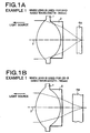
- Figs. 1A and 1B are schematic views showing the states where the objective lens in accordance with Example 1 of the present invention is used for DVD and CD-R, respectively;
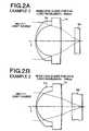
- Figs. 2A and 2B are schematic views showing the states where the objective lens in accordance with Example 2 of the present invention is used for DVD and CD-R, respectively;
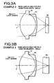
- Figs. 3A and 3B are schematic views showing the states where the objective lens in accordance with Example 3 of the present invention is used for DVD and CD-R, respectively;
- Figs. 4A and 4B are schematic views showing the states where the objective lens in accordance with Example 4 of the present invention is used for DVD and CD-R, respectively;
- Figs. 5A and 5B are schematic views showing the states where the objective lens in accordance with Example 5 of the present invention is used for DVD and CD-R, respectively;
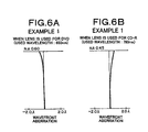
- Figs. 6A and 6B are aberration charts showing wavefront aberrations in Example 1 of the present invention;
- Figs. 7A and 7B are aberration charts showing wavefront aberrations in Example 2 of the present invention;
- Figs. 8A and 8B are aberration charts showing wavefront aberrations in Example 3 of the present invention;
- Figs. 9A and 9B are aberration charts showing wavefront aberrations in Example 4 of the present invention;
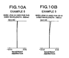
- Figs. 10A and 10B are aberration charts showing wavefront aberrations in Example 5 of the present invention; and
- Fig. 11 is a schematic view showing the optical pickup apparatus in accordance with an embodiment of the present invention.
- In the following, an embodiment of the present invention will be explained with reference to the drawings.
- First, with reference to Fig. 11, an optical pickup apparatus using the objective lens for optical recording media in accordance with an embodiment of the present invention will be explained.
- In this optical pickup apparatus, a
semiconductor laser laser beam 12 when power is supplied thereto from anLD power source 11A, ahalf mirror 13 reflects thelaser beam 12, acollimator lens 4 turns thus reflectedlaser beam 12 into parallel light, and an objective lens 5 converts the parallel light into convergent light, with which arecording region 6P of an optical disc 6 is irradiated. Thesemiconductor laser 11B is a light source for outputting a laser beam in a near-infrared region having a wavelength of about 780 nm for CD-R (recordable optical disc), whereas thesemiconductor laser 11C is a light source for outputting a laser beam, for example, in a visible light having a wavelength of 650 nm for DVD (digital versatile disc). Thelaser beam 12 outputted from one of thesemiconductor lasers half mirror 13 by way of ahalf mirror 11D. Achangeover switch 11E is disposed between theLD power source 11A and thesemiconductor lasers changeover switch 11E is operated, power is supplied to one of thesemiconductor lasers - In the
recording region 6P, pits carrying signal information are arranged in a track. The reflected light oflaser beam 12 used for reproducing the recording information fromregion 6P is made incident on thehalf mirror 13 by way of the objective lens 5 andcollimator lens 4 while carrying the signal information, and is transmitted through thehalf mirror 13, so as to be made incident on a four-part photodiode 7. The respective quantities of light received at the four-part photodiode 7 are arithmetically operated, whereby data signals and respective error signals for focusing and tracking are obtained. - Since the
half mirror 13 is inserted in the optical path of the return light from the optical disc 6 in a state tilted by 45°, it acts like a cylindrical lens, so that the light beam transmitted through thehalf mirror 13 has an astigmatism, whereby the amount of focusing error is determined according to the form of the beam spot of return light on the four-part photodiode 7. Here, thecollimator lens 4 can be omitted depending on the circumstances. Also, a grating may be inserted between thesemiconductor lasers half mirror 13, such that tracking errors can be detected by use of three beams. - Thus, the optical pickup apparatus in accordance with this embodiment is configured such that signals can be recorded and reproduced for any optical disc 6 of CD-R and DVD.
- Here, each of the CD-R and DVD has a protective sheet made of PC (polycarbonate).
- Meanwhile, the geometric thickness of CD-R is standardized at 1.2 mm, and one having a refractive index of 1.55 is often used. As for the DVD, on the other hand, one having a geometric thickness of 0.6 mm and a refractive index of 1.58 is often used. Consequently, for securely carrying out focusing on each optical disc 6, it is necessary to provide a configuration yielding focusing actions different from each other for the respective wavelengths of light for recording/reproducing the different kinds of discs.
- Therefore, the above-mentioned optical pickup apparatus is provided with the objective lens 5 in which a plurality of
lenses 1, 2 whose refractive index changing ratios differ from each other according to wavelengths are cemented together as shown in Fig. 11, so that both CD-R and DVD can be recorded and reproduced. - When a DVD is disposed at a predetermined position (on a turntable) for recording or reproducing, the
laser beam 12 having a wavelength of 650 nm (λ1) from thesemiconductor laser 11C is made incident on the objective lens 5 while in a substantially parallel state. In this case, theincident laser beam 12 is converged onto a recording surface of the DVD by the objective lens 5. - When a CD-R is disposed at a predetermined position (on the turntable) for recording or reproducing, the
laser beam 12 having a wavelength of 780 nm (λ2) from thesemiconductor laser 11B is made incident on the objective lens 5 while in a substantially parallel state. In this case, theincident laser beam 12 is converged onto a recording surface of the CD-R by the objective lens 5. - Here, the objective lens is made of a complex lens comprising a plurality of lenses having refractive index changing ratios different from each other according to wavelengths.
- The above-mentioned objective lens 5 will now be explained specifically with reference to Examples 1 to 5.
- When a
DVD 6A is disposed at a predetermined position (on a turntable) for recording or reproducing as shown in Fig. 1A, thelaser beam 12 having a wavelength of 650 nm (λ1) is made incident on the objective lens 5 while in a substantially parallel state. In this case, theincident laser beam 12 is converged onto a recording surface of theDVD 6A by the objective lens 5. - When a CD-
R 6B is disposed at a predetermined position (on the turntable) for recording or reproducing as shown in Fig. 1B, on the other hand, thelaser beam 12 having a wavelength of 780 nm (λ2) is made incident on the objective lens 5 while in a substantially parallel state. In this case, theincident laser beam 12 is converged onto a recording surface of the CD-R 6B by the objective lens 5. - The objective lens 5 in Example 1 comprises, successively from the light source side, a biconvex lens 1 having a convex surface constituted by an aspheric surface (represented by the following aspheric surface expression, ditto for the following aspheric surfaces) directed onto the light source side and a convex surface with a stronger curvature directed onto the light convergent side, and a
negative meniscus lens 2 having a concave surface directed onto the light source side and a substantially planar aspheric surface directed onto the light convergent side, which are cemented together. Here, the cemented surface is a spherical surface. Since both sides of the objective lens 5 are constituted by aspheric surfaces, the freedom in designing of aberration correction and the correcting effect can be improved greatly.
where - Z is the length of the perpendicular to a tangential plane (plane perpendicular to the optical axis) of an apex of the aspheric surface from a point on the aspheric surface having a distance Y from the optical axis;
- Y is the distance from the optical axis;
- Ai is the aspheric surface coefficient (i = 2 to 5);
- R is the radius of curvature of aspheric surface near the optical axis; and
- K is the eccentricity.
- The upper part of the following Table 1 shows lens data (radius of curvature R, surface space D, and refractive index N with respect to λ = 650 nm and 780 nm) of the objective lens 5 in accordance with Example 1.
- As can be seen from Table 1, the difference between the respective refractive indices of the two
lenses 1, 2 constituting the objective lens 5 is very small, i.e., 0.00057, for the light having a wavelength λ of 650 nm (λ1), whereas it is 0.011 for the light having a wavelength λ of 780 nm (λ2). As a consequence, the refractive index at the boundary (cemented surface) of bothlenses 1, 2 is negligible with respect to the light having a wavelength λ of 650 nm (λ1). Therefore, on a design for the cemented surface, it will be sufficient if the designing for lowering the aspheric aberration of the whole objective lens 5 is carried out while taking account of the light having a wavelength of 780 nm alone. Namely, in this Example, lens glass materials for the twolenses 1, 2 constituting the objective lens 5 are delicately combined together, so as to adjust the lens curvature for one wavelength of light in the two wavelengths in use, whereby the objective lens 5 having a small spherical aberration commonly usable for DVD and CD-R is constructed. - The middle part of Table 1 indicates the aspheric surface coefficient of each aspheric surface.
- The lower part of Table 1 indicates the focal length of objective lens 5, the diameter of luminous flux incident on the objective lens 5, and the numerical aperture of objective lens 5 in each of the cases where DVD and CD-R are set as the optical recording medium.
- The objective lens 5 in Example 2 comprises, successively from the light source side, a
negative meniscus lens 2a having an aspheric convex surface directed onto the light source side and a concave surface directed onto the light convergent side, and apositive lens 1a having a convex surface with a stronger curvature directed onto the light source side and a substantially flat aspheric surface directed onto the light convergent side, which are cemented together. Here, the cemented surface is a spherical surface. - The upper part of the following Table 2 shows lens data (radius of curvature R, surface space D, and refractive index N with respect to λ = 650 nm and 780 nm) of the objective lens 5 in accordance with Example 2.
- As can be seen from Table 2, the difference between the respective refractive indices of the two
lenses - The middle part of Table 2 indicates the aspheric surface coefficient of each aspheric surface.
- The lower part of Table 2 indicates the focal length of objective lens 5, the diameter of luminous flux incident on the objective lens 5, and the numerical aperture of objective lens 5 in each of the cases where DVD and CD-R are set as the optical recording medium.
- The objective lens 5 in Example 3 comprises, successively from the light source side, a
biconvex lens 1b having a convex surface with a stronger curvature directed onto the light convergent side, and anegative meniscus lens 2b having a concave surface directed onto the light source side, which are cemented together. All the lens surfaces including the cemented surface are made aspheric. - The upper part of the following Table 3 shows lens data (radius of curvature R, surface space D, and refractive index N with respect to λ = 650 nm and 780 nm) of the objective lens 5 in accordance with Example 3.
- As can be seen from Table 3, the difference between the respective refractive indices of the two
lenses - The middle part of Table 3 indicates the aspheric surface coefficient of each aspheric surface.
- The lower part of Table 3 indicates the focal length of objective lens 5, the diameter of luminous flux incident on the objective lens 5, and the numerical aperture of objective lens 5 in each of the cases where DVD and CD-R are set as the optical recording medium.
- The objective lens 5 in Example 4 comprises, successively from the light source side, a
negative meniscus lens 2c having a convex surface directed onto the light source side, and abiconvex lens 1c having a surface with a stronger curvature directed onto the light source side, which are cemented together. All the lens surfaces including the cemented surface are made aspheric. - The upper part of the following Table 4 shows lens data (radius of curvature R, surface space D, and refractive index N with respect to λ = 650 nm and 780 nm) of the objective lens 5 in accordance with Example 4.
- As can be seen from Table 4, the difference between the respective refractive indices of the two
lenses - The middle part of Table 4 indicates the aspheric surface coefficient of each aspheric surface.
- The lower part of Table 4 indicates the focal length of objective lens 5, the diameter of luminous flux incident on the objective lens 5, and the numerical aperture of objective lens 5 in each of the cases where DVD and CD-R are set as the optical recording medium.
- The objective lens 5 in Example 5 comprises, successively from the light source side, a
negative meniscus lens 2d having a convex surface directed onto the light source side, abiconvex lens 1d having a surface with a stronger curvature directed onto the light source side, and anegative meniscus lens 3d having a concave surface directed onto the light source side, which are cemented together. Here, both sides of the objective lens 5 are aspheric surfaces, whereas the cemented surfaces are spherical surfaces. - The upper part of the following Table 5 shows lens data (radius of curvature R, surface space D, and refractive index N with respect to λ = 650 nm and 780 nm) of the objective lens 5 in accordance with Example 5.
- As can be seen from Table 5, the difference between the respective refractive indices of each pair of adjacent cemented lenses in the three
lenses - The middle part of Table 5 indicates the aspheric surface coefficient of each aspheric surface.
- The lower part of Table 5 indicates the focal length of objective lens 5, the diameter of luminous flux incident on the objective lens 5, and the numerical aperture of objective lens 5 in each of the cases where DVD and CD-R are set as the optical recording medium.
- Figs. 6A to 10B are wavefront aberration charts for the above-mentioned Examples 1 to 5, from which it is clear that each Example is suitable for both DVD and CD-R.
- The objective lens of the present invention can be modified in various manners without being restricted to that of the above-mentioned embodiment. For example, a plastic material can be used as a material for forming the lenses. Further, a resin curable by heat or light may be molded into a desirable form while being attached to one lens, whereby a thin lens cemented to one lens can be formed.
- If the performance up to about NA = 0.6 is secured for light having a wavelength of 780 nm (λ1), for example, when determining the form of cemented lens surface, then a specific stop (such as a liquid crystal shutter, a wavelength-selective filter, or the like) for adjusting the NA of DVD and CD-R is unnecessary.
- The optical recording media to be recorded and reproduced in the optical pickup apparatus of the present invention are not restricted to DVD and CD-R, whereby the present invention is applicable to any case where a single optical pickup apparatus is used for recording and reproducing two optical recording media which are different from each other in terms of the wavelength regions in use.
- Though the optical pickup apparatus in accordance with the above-mentioned embodiment is provided with individual light sources for outputting respective wavelengths of light different from each other, a single light source which can output two wavelengths of light different from each other may be provided instead.
- Though λ1 and λ2 are 650 nm and 780 nm, respectively, in the above-mentioned embodiment, operations and effects equivalent to those mentioned above can also be obtained when λ1 and λ2 are 780 nm and 650 nm, respectively.
- In the objective lens for optical recording media in accordance with the present invention and the optical pickup apparatus using the same, as explained in the foregoing, adjacent lenses constituting the objective lens are constituted by respective materials having refractive index changing ratios different from each other, such that their refractive indices are substantially identical to each other for wavelength λ1 of light and differ from each other for wavelength λ2 of light, whereas each lens has a form configured so as to suppress aberration in the objective lens as a whole.
- Since the refractive index changes depending on the wavelength of light, light is refracted at cemented surfaces or opposed surfaces in a cemented lens or a lens whose opposite surfaces are very close to each other, whereby it is quite difficult to find out a lens form whose aberration becomes favorable even just for two wavelengths.
- Therefore, choosing lens forming materials such that the refractive indices of two lenses become substantially equal to each other only at one wavelength while taking account of the fact that it will be sufficient if only the other wavelength is considered as for the fluctuation in amount of aberration caused by the refraction of light at the cemented surface, the present invention selects the form of this cemented surface, thereby enabling two wavelengths of light to be converged, in a state where aberration is favorably corrected, at the recording surfaces of the optical recording media having respective thickness values corresponding thereto.
- Hence, there is no fear of the apparatus enlarging its size, complicating its structure, and raising its manufacturing cost as in the conventional objective lenses for optical recording media and optical pickup apparatus in order to ameliorate the aberration.
TABLE 1 Lens Surface Radius of Curvature(R) Surface Space(D) Refractive index(N) λ=650nm λ=780nm 1(aspheric) 2.65760 2.80 1.69330 1.69043 2(spheric) -2.34030 0.20 1.69273 1.67943 3(aspheric) -22.0422 1.00000 1.00000 - When the lens surface is an aspheric surface, the radius of curvature (R) indicates the radius of curvature near the optical axis.
Aspheric surface coefficient(1st surface) A2 3.651604849 × 10⁻³ A3 8.849215538 × 10⁻⁵ A4 6.966383926 × 10⁻⁶ A5 -2.584690036 × 10⁻⁶ K 0.0 Aspheric surface coefficient(3rd surface) A2 8.543160379 × 10⁻³ A3 -2.747241378 × 10⁻³ A4 3.731236055 × 10⁻⁴ A5 -1.635188327 × 10⁻⁵ K 0.0
focal length f=3.598mm
incident luminous flux diameter Φ 4.32mm
numerical aperture NA=0.60
For CD-R
focal length f=3.583mm
incident luminous flux diameter Φ3.23mm
numerical aperture NA=0.45Table 2 Lens Surface Radius of Curvature(R) Surface Space(D) Refractive index(N) λ=650nm λ=780nm 1(aspheric) 2.65760 0.10 1.69273 1.67943 2(spheric) 1.79080 2.90 1.69330 1.69043 3(aspheric) -22.0422 1.00000 1.00000 - When the lens surface is an aspheric surface, the radius of curvature (R) indicates the radius of curvature near the optical axis.
Aspheric surface coefficient(1st surface) A2 3.647701780 × 10⁻³ A3 8.885444661 × 10⁻⁵ A4 6.646338616 × 10⁻⁶ A5 -2.546979068 × 10⁻⁶ K 0.0 Aspheric surface coefficient(3rd surface) A2 8.517314565 × 10⁻³ A3 -2.738054280 × 10⁻³ A4 3.715198332 × 10⁻⁴ A5 -1.602803438 × 10⁻⁵ K 0.0
focal length f=3.599mm
incident luminous flux diameter Φ 4.32mm
numerical aperture NA=0.60
For CD-R
focal length f=3.591mm
incident luminous flux diameter Φ 3.23mm
numerical aperture NA=0.45Table 3 Lens Surface Radius of Curvature(R) Surface Space(D) Refractive index(N) λ=650nm λ=780nm 1(aspheric) 2.66670 3.00 1.61527 1.61290 2(aspheric) -2.27290 0.20 1.61543 1.60263 3(aspheric) -7.09950 1.00000 1.00000 - When the lens surface is an aspheric surface, the radius of curvature (R) indicates the radius of curvature near the optical axis.
Aspheric surface coefficient(1st surface) A2 2.737129687 × 10⁻³ A3 -8.973968245 × 10⁻⁵ A4 1.615669007 × 10⁻⁵ A5 -1.031306979 × 10⁻⁵ K 0.0 Aspheric surface coefficient(2nd surface) A2 -8.364324365 × 10⁻⁴ A3 1.360865731 × 10⁻⁴ A4 3.256145465 × 10⁻⁵ A5 7.989004405 × 10⁻⁶ K 1.025648198 Aspheric surface coefficient(3rd surface) A2 1.091002882 × 10⁻² A3 -4.517808156 × 10⁻³ A4 6.863166966 × 10⁻⁴ A5 -4.050313980 × 10⁻⁵ K 0.0
focal length f=3.600mm
incident luminous flux diameter Φ 4.32mm
numerical aperture NA=0.60
For CD-R
focal length f=3.590mm
incident luminous flux diameter Φ3.23mm
numerical aperture NA=0.45Table 4 Lens Surface Radius of Curvature(R) Surface Space(D) Refractive index(N) λ=650nm λ=780nm 1(aspheric) 2.66670 0.10 1.61543 1.60263 2(aspheric) 2.28140 3.10 1.61527 1.61290 3(aspheric) -7.09950 1.00000 1.00000 - When the lens surface is an aspheric surface, the radius of curvature (R) indicates the radius of curvature near the optical axis.
Aspheric surface coefficient(1st surface) A2 2.733562707 × 10⁻³ A3 -9.125805890 × 10⁻⁵ A4 1.743103824 × 10⁻⁵ A5 -1.046751456 × 10⁻⁵ K 0.0 Aspheric surface coefficient(2nd surface) A2 3.307481221 × 10⁻³ A3 -1.789070427 × 10⁻⁴ A4 -3.474611465 × 10⁻⁵ A5 -7.895685988 × 10⁻⁶ K 1.378244334 Aspheric surface coefficient(3rd surface) A2 1.084485345 × 10⁻² A3 -4.441698767 × 10⁻³ A4 6.567728685 × 10⁻⁴ A5 -3.671804744 × 10⁻⁵ K 0.0
focal length f=3.600mm
incident luminous flux diameter Φ 4.32mm
numerical aperture NA=0.60
For CD-R
focal length f=3.606mm
incident luminous flux diameter Φ 3.25mm
numerical aperture NA=0.45Table 5 Lens Surface Radius of Curvature(R) Surface Space(D) Refractive index(N) λ=650nm λ=780nm 1(aspheric) 2.66670 0.10 1.61543 1.60263 2(spheric) 2.13650 2.90 1.61527 1.61290 3(spheric) -2.87910 0.20 1.61543 1.60263 4(aspheric) -7.09950 1.00000 1.00000 - When the lens surface is an aspheric surface, the radius of curvature (R) indicates the radius of curvature near the optical axis.
Aspheric surface coefficient(1st surface) A2 2.733562707 × 10⁻³ A3 -9.125805890 × 10⁻⁵ A4 1.743103824 × 10⁻⁵ A5 -1.046751456 × 10⁻⁵ K 0.0 Aspheric surface coefficient(4th surface) A2 1.084485345 × 10⁻² A3 -4.441698767 × 10⁻³ A4 6.567728685 × 10⁻⁴ A5 -3.671804744 × 10⁻⁵ K 0.0
focal length f=3.600mm
incident luminous flux diameter Φ4.32mm
numerical aperture NA=0.60
For CD-R
focal length f=3.587mm
incident luminous flux diameter Φ3.23mm
numerical aperture NA=0.45 - An objective lens for converging two wavelengths of light to their predetermined positions is constituted by two or three lenses. Respective materials for forming adjacent lenses are chosen such that the respective refractive indices of adjacent lenses substantially equal each other with respect to only one of the two wavelengths of light, whereas the form of each lens surface is configured so as to suppress aberration in the objective lens as a whole.
Claims (10)
- Objective lens (5) adapted to be commonly usable for irradiating first (DVD) and second (CD-R) kinds of optical recording media,
said first kind of optical recording media (DVD) having a first wavelength (λ1) of light for recording/reproducing,
said second kind of optical recording media (CD-R) having a second wavelength (λ2) of light for recording/reproducing,
said first wavelength (λ1) being different from said second wavelength (λ2),
said objective lens (5) being composed of first and second lenses (1, 2) disposed in a luminous flux,
said first and second lenses (1, 2) being constituted by respective materials different from each other,
said first and second lenses (1, 2) having lens surfaces with a form configured to suppress spherical aberration in said objective lens (5) as a whole, and
said first and second lenses (1, 2) being cemented together,
characterized in that
with respect to light having said first wavelength (λ1) the refraction index (N1(λ1)) of said first lens (1) is substantially equal to the refraction index (N2(λ1)) of said second lens (2) such that refraction of light having said first wavelength (λ1) at the boundary between said first lens (1) and said second lens (2) is negligible,
whereas with respect to light having said second wavelength (λ2) the refraction index (N1(λ2)) of said first lens (1) differs from the refraction index (N2(λ2)) of said second lens (2). - Objective lens according to claim 1, wherein with respect to light having said first wavelength (λ1) the ratio of said refraction index (N1 (λ1)) of said first lens (1) and said refraction index (N2(λ1)) of said second lens (2) has a value between 0.99966 and 1.00034.
- An objective lens according to claim 1 or 2, wherein said cemented surface is made aspheric.
- An objective lens according to any of claims 1 to 3, wherein said first wavelength λ1 is one of wavelengths of 650 nm and 780 nm for recording and reproducing one of DVD and CD-R, whereas said second wavelength λ2 is the other of wavelengths of 650 nm and 780 nm for recording and reproducing the other of DVD and CD-R.
- An optical pickup apparatus comprising the objective lens (5) according to any of claims 1 to 4.
- Objective lens (5) adapted to be commonly usable for irradiating first (DVD) and second (CD-R) kinds of optical recording media,
said first kind of optical recording media (DVD) having a first wavelength (λ1) of light for recording/reproducing,
said second kind of optical recording media (CD-R) having a second wavelength (λ2) of light for recording/reproducing,
said first wavelength (λ1) being different from said second wavelength (λ2),
said objective lens (5) being composed of first, second and third lenses (1d, 2d, 3d) disposed in a luminous flux,
at least adjacent lenses of said first, second and third lenses (1d, 2d, 3d) being constituted by respective materials different from each other,
said first, second and third lenses (1d, 2d, 3d) having lens surfaces with a form configured to suppress spherical aberration in said objective lens (5) as a whole, and
said first, second and third lenses (1d, 2d, 3d) being cemented together,
characterized in that
with respect to light having said first wavelength (λ1) the refraction index (N1(λ1)) of said first lens (1d) is substantially equal to the refraction index (N2(λ1)) of said second lens (2d),
and the refraction index (N2(λ1)) of said second lens (2d) is substantially equal to the refraction index of said third lens (3d), such that refraction of light having said first wavelength (λ1) at the boundaries between said first lens (1d) and said second lens (2d) and between said second lens (2d) and said third lens (3d) is negligible, whereas for light having said second wavelength (λ2) the refraction index (N1(λ2)) of said first lens (1d) differs from the refraction index (N2 (λ2)) of said second lens (2d) and the refraction index (N2(λ2)) of said second lens (2d) differs from the refraction index (N3(λ2)) of said third lens (3d). - Objective lens (5) according to claim 6, wherein with respect to light having said first wavelength (λ1) the ratio of said refraction index (N1 (λ1)) of said first lens (1d) and said refraction index (N2(λ1)) of said second lens (2d) and the ratio of said refraction index (N2(λ1)) of said second lens (2d) and said refraction index (N3(λ1)) of said third lens (3d) have a value between 0.99966 and 1.00034, respectively.
- An objective lens (5) according to any of claims 5 to 7, wherein at least one of said cemented surfaces is made aspheric.
- An objective lens (5) according to any of claims 5 to 8, wherein said first wavelength λ1 is one of wavelengths of 650 nm and 780 nm for recording and reproducing one of DVD and CD-R, whereas said second wavelength λ2 is the other of wavelengths of 650 nm and 780 nm for recording and reproducing the other of DVD and CD-R.
- An optical pickup apparatus comprising the objective lens (5) according to any of claims 5 to 9.
Applications Claiming Priority (2)
| Application Number | Priority Date | Filing Date | Title |
|---|---|---|---|
| JP2000185281A JP3810051B2 (en) | 2000-06-20 | 2000-06-20 | Objective lens for optical recording medium and optical pickup device using the same |
| JP2000185281 | 2000-06-20 |
Publications (3)
| Publication Number | Publication Date |
|---|---|
| EP1174866A2 EP1174866A2 (en) | 2002-01-23 |
| EP1174866A3 EP1174866A3 (en) | 2004-05-26 |
| EP1174866B1 true EP1174866B1 (en) | 2006-05-10 |
Family
ID=18685618
Family Applications (1)
| Application Number | Title | Priority Date | Filing Date |
|---|---|---|---|
| EP01114363A Expired - Lifetime EP1174866B1 (en) | 2000-06-20 | 2001-06-13 | Objective lens for different optical recording media and optical pickup apparatus using the same |
Country Status (3)
| Country | Link |
|---|---|
| US (1) | US6646817B2 (en) |
| EP (1) | EP1174866B1 (en) |
| JP (1) | JP3810051B2 (en) |
Families Citing this family (14)
| Publication number | Priority date | Publication date | Assignee | Title |
|---|---|---|---|---|
| JP2001356263A (en) * | 2000-06-12 | 2001-12-26 | Pioneer Electronic Corp | Combined objective lens, optical pickup device, optical recording and reproducing device and method for manufacturing combined objective lens |
| US20030107824A1 (en) * | 2001-12-04 | 2003-06-12 | Pentax Corporation | Cemented objective lens and manufacturing method thereof |
| JP2004061519A (en) * | 2002-06-06 | 2004-02-26 | Enplas Corp | Objective for optical pickup |
| US6850669B2 (en) * | 2002-10-31 | 2005-02-01 | Avanex Corporation | Package for optical filter device |
| CN100454074C (en) * | 2002-12-10 | 2009-01-21 | 旭硝子株式会社 | Objective lens for optical information recording medium |
| US7313074B2 (en) | 2003-06-30 | 2007-12-25 | Ricoh Company, Ltd. | Objective lens, optical, pickup and optical information processing apparatus using the same |
| US7535656B2 (en) * | 2005-06-15 | 2009-05-19 | Daylight Solutions, Inc. | Lenses, optical sources, and their couplings |
| JP4819447B2 (en) | 2005-09-02 | 2011-11-24 | キヤノン株式会社 | Optical system and imaging apparatus having the same |
| US7843792B2 (en) * | 2006-06-21 | 2010-11-30 | Hoya Corporation | Optical information recording /reproducing device and objective lens for the same |
| US7920455B2 (en) * | 2006-08-23 | 2011-04-05 | Panasonic Corporation | Complex optical element and optical pickup |
| US7778139B2 (en) | 2006-10-17 | 2010-08-17 | Hoya Corporation | Optical information recording/reproducing device and objective lens for the same |
| JP3926380B1 (en) * | 2006-12-07 | 2007-06-06 | マイルストーン株式会社 | Imaging lens |
| JP5153351B2 (en) * | 2008-01-18 | 2013-02-27 | キヤノン株式会社 | Zoom lens and optical apparatus having the same |
| CN105445824B (en) * | 2014-08-20 | 2017-02-22 | 清华大学 | LED optical communication receiving lens and LED optical communication system |
Family Cites Families (7)
| Publication number | Priority date | Publication date | Assignee | Title |
|---|---|---|---|---|
| FR2642883B1 (en) * | 1989-02-09 | 1995-06-02 | Asahi Optical Co Ltd | |
| JPH0519162A (en) * | 1991-05-02 | 1993-01-29 | Asahi Optical Co Ltd | Objective lens and method for measuring the lens |
| US5225928A (en) * | 1991-10-07 | 1993-07-06 | Spectra-Physics Laserplane, Inc. | Focus compensating lens for use in extreme temperatures |
| JPH09251645A (en) * | 1996-03-15 | 1997-09-22 | Sony Corp | Recording medium recording and reproducing device and method therefor |
| JPH10188322A (en) * | 1996-12-26 | 1998-07-21 | Nec Corp | Optical head |
| JP2000090477A (en) * | 1998-09-09 | 2000-03-31 | Pioneer Electronic Corp | Optical pickup, information reproducing device and information recording device |
| KR100657251B1 (en) * | 2000-01-14 | 2006-12-19 | 삼성전자주식회사 | Optical pickup device |
-
2000
- 2000-06-20 JP JP2000185281A patent/JP3810051B2/en not_active Expired - Fee Related
-
2001
- 2001-05-25 US US09/864,236 patent/US6646817B2/en not_active Expired - Fee Related
- 2001-06-13 EP EP01114363A patent/EP1174866B1/en not_active Expired - Lifetime
Also Published As
| Publication number | Publication date |
|---|---|
| EP1174866A2 (en) | 2002-01-23 |
| US6646817B2 (en) | 2003-11-11 |
| JP3810051B2 (en) | 2006-08-16 |
| EP1174866A3 (en) | 2004-05-26 |
| JP2002006210A (en) | 2002-01-09 |
| US20020012175A1 (en) | 2002-01-31 |
Similar Documents
| Publication | Publication Date | Title |
|---|---|---|
| EP1154417B1 (en) | Optical pick-up apparatus | |
| US6400672B2 (en) | Method for recording/reproducing optical information recording medium, optical pickup apparatus, objective lens and design method of objective lens | |
| EP1184855B1 (en) | Objective lens for optical recording media and optical pickup apparatus using the same | |
| US8184520B2 (en) | Optical pickup device having chromatic aberration correction lens | |
| US6590717B2 (en) | Optical system for optical disk, optical head unit for optical disk, and optical drive device | |
| US20010043407A1 (en) | Optical pickup apparatus and objective lens | |
| EP1174866B1 (en) | Objective lens for different optical recording media and optical pickup apparatus using the same | |
| EP1096483B1 (en) | Optical pickup | |
| US20050259554A1 (en) | Objective optical system and optical pickup device using it | |
| US6363037B1 (en) | Optical pickup apparatus with objective lens having a phase shift section | |
| US20030002175A1 (en) | Objective lens and optical pickup apparatus | |
| EP2202544A1 (en) | Aspheric lens and optical pickup including the same | |
| EP1906399B1 (en) | Object lens for an optical pickup device | |
| EP1168317A1 (en) | Objective lens and optical pickup device | |
| KR101044419B1 (en) | Lens and optical system, optical head and optical disk apparatus using lens | |
| US20030090987A1 (en) | Objective lens for optical recording medium and optical pickup apparatus | |
| EP1197960B1 (en) | Objective lens for optical recording media and optical pickup apparatus using the same | |
| US6545823B2 (en) | Double-wavelength aperture restricting filter and optical pickup apparatus using the same | |
| EP1318510A2 (en) | Optical disk and recording/reproducing apparatus | |
| US20070111142A1 (en) | Optical disk and recording/reproducing apparatus | |
| JPS60247213A (en) | Objective lens for optical pickup | |
| KR20050030225A (en) | Scanning device including an objective system formed of a single material |
Legal Events
| Date | Code | Title | Description |
|---|---|---|---|
| PUAI | Public reference made under article 153(3) epc to a published international application that has entered the european phase |
Free format text: ORIGINAL CODE: 0009012 |
|
| 17P | Request for examination filed |
Effective date: 20010615 |
|
| AK | Designated contracting states |
Kind code of ref document: A2 Designated state(s): AT BE CH CY DE DK ES FI FR GB GR IE IT LI LU MC NL PT SE TR |
|
| AX | Request for extension of the european patent |
Free format text: AL;LT;LV;MK;RO;SI |
|
| PUAL | Search report despatched |
Free format text: ORIGINAL CODE: 0009013 |
|
| AK | Designated contracting states |
Kind code of ref document: A3 Designated state(s): AT BE CH CY DE DK ES FI FR GB GR IE IT LI LU MC NL PT SE TR |
|
| AX | Request for extension of the european patent |
Extension state: AL LT LV MK RO SI |
|
| RIC1 | Information provided on ipc code assigned before grant |
Ipc: 7G 11B 7/125 B Ipc: 7G 11B 7/135 A |
|
| 17Q | First examination report despatched |
Effective date: 20040922 |
|
| AKX | Designation fees paid |
Designated state(s): FR NL |
|
| REG | Reference to a national code |
Ref country code: DE Ref legal event code: 8566 |
|
| RAP1 | Party data changed (applicant data changed or rights of an application transferred) |
Owner name: FUJINON CORPORATION |
|
| GRAP | Despatch of communication of intention to grant a patent |
Free format text: ORIGINAL CODE: EPIDOSNIGR1 |
|
| GRAS | Grant fee paid |
Free format text: ORIGINAL CODE: EPIDOSNIGR3 |
|
| GRAA | (expected) grant |
Free format text: ORIGINAL CODE: 0009210 |
|
| AK | Designated contracting states |
Kind code of ref document: B1 Designated state(s): FR NL |
|
| ET | Fr: translation filed | ||
| PLBE | No opposition filed within time limit |
Free format text: ORIGINAL CODE: 0009261 |
|
| STAA | Information on the status of an ep patent application or granted ep patent |
Free format text: STATUS: NO OPPOSITION FILED WITHIN TIME LIMIT |
|
| 26N | No opposition filed |
Effective date: 20070213 |
|
| PGFP | Annual fee paid to national office [announced via postgrant information from national office to epo] |
Ref country code: NL Payment date: 20120626 Year of fee payment: 12 |
|
| PGFP | Annual fee paid to national office [announced via postgrant information from national office to epo] |
Ref country code: FR Payment date: 20120619 Year of fee payment: 12 |
|
| REG | Reference to a national code |
Ref country code: NL Ref legal event code: V1 Effective date: 20140101 |
|
| REG | Reference to a national code |
Ref country code: FR Ref legal event code: ST Effective date: 20140228 |
|
| PG25 | Lapsed in a contracting state [announced via postgrant information from national office to epo] |
Ref country code: NL Free format text: LAPSE BECAUSE OF NON-PAYMENT OF DUE FEES Effective date: 20140101 |
|
| PG25 | Lapsed in a contracting state [announced via postgrant information from national office to epo] |
Ref country code: FR Free format text: LAPSE BECAUSE OF NON-PAYMENT OF DUE FEES Effective date: 20130701 |