EP1174776A1 - Mechanical timepiece with posture detecting part and optical timed annular balance rotation detecting part - Google Patents
Mechanical timepiece with posture detecting part and optical timed annular balance rotation detecting part Download PDFInfo
- Publication number
- EP1174776A1 EP1174776A1 EP00905403A EP00905403A EP1174776A1 EP 1174776 A1 EP1174776 A1 EP 1174776A1 EP 00905403 A EP00905403 A EP 00905403A EP 00905403 A EP00905403 A EP 00905403A EP 1174776 A1 EP1174776 A1 EP 1174776A1
- Authority
- EP
- European Patent Office
- Prior art keywords
- balance
- mechanical timepiece
- hairspring
- rotation
- wheel
- Prior art date
- Legal status (The legal status is an assumption and is not a legal conclusion. Google has not performed a legal analysis and makes no representation as to the accuracy of the status listed.)
- Withdrawn
Links
- 230000003287 optical effect Effects 0.000 title description 3
- 230000033001 locomotion Effects 0.000 claims abstract description 35
- 238000001514 detection method Methods 0.000 claims description 24
- 238000004804 winding Methods 0.000 description 40
- 230000009467 reduction Effects 0.000 description 19
- 230000007246 mechanism Effects 0.000 description 12
- 239000010437 gem Substances 0.000 description 8
- 229910001751 gemstone Inorganic materials 0.000 description 8
- 230000008859 change Effects 0.000 description 7
- 230000007423 decrease Effects 0.000 description 6
- 239000004020 conductor Substances 0.000 description 5
- 238000000034 method Methods 0.000 description 5
- 230000008569 process Effects 0.000 description 5
- XEEYBQQBJWHFJM-UHFFFAOYSA-N Iron Chemical compound [Fe] XEEYBQQBJWHFJM-UHFFFAOYSA-N 0.000 description 4
- 239000003990 capacitor Substances 0.000 description 4
- 230000003247 decreasing effect Effects 0.000 description 4
- 230000004907 flux Effects 0.000 description 4
- 230000000694 effects Effects 0.000 description 3
- 239000013013 elastic material Substances 0.000 description 3
- 238000002474 experimental method Methods 0.000 description 3
- 230000006698 induction Effects 0.000 description 3
- 238000005259 measurement Methods 0.000 description 3
- 238000004088 simulation Methods 0.000 description 3
- 230000005674 electromagnetic induction Effects 0.000 description 2
- 239000011810 insulating material Substances 0.000 description 2
- 229910052742 iron Inorganic materials 0.000 description 2
- WABPQHHGFIMREM-UHFFFAOYSA-N lead(0) Chemical compound [Pb] WABPQHHGFIMREM-UHFFFAOYSA-N 0.000 description 2
- 238000004519 manufacturing process Methods 0.000 description 2
- 239000000463 material Substances 0.000 description 2
- 239000002184 metal Substances 0.000 description 2
- 229910052751 metal Inorganic materials 0.000 description 2
- 239000010979 ruby Substances 0.000 description 2
- 229910001750 ruby Inorganic materials 0.000 description 2
- 229910001220 stainless steel Inorganic materials 0.000 description 2
- 239000010935 stainless steel Substances 0.000 description 2
- 230000007704 transition Effects 0.000 description 2
- 241000670727 Amida Species 0.000 description 1
- 229910001369 Brass Inorganic materials 0.000 description 1
- 229910000942 Elinvar Inorganic materials 0.000 description 1
- WHXSMMKQMYFTQS-UHFFFAOYSA-N Lithium Chemical compound [Li] WHXSMMKQMYFTQS-UHFFFAOYSA-N 0.000 description 1
- BQCADISMDOOEFD-UHFFFAOYSA-N Silver Chemical compound [Ag] BQCADISMDOOEFD-UHFFFAOYSA-N 0.000 description 1
- 230000009471 action Effects 0.000 description 1
- 238000013459 approach Methods 0.000 description 1
- 230000005540 biological transmission Effects 0.000 description 1
- 239000010951 brass Substances 0.000 description 1
- 238000004364 calculation method Methods 0.000 description 1
- 244000145845 chattering Species 0.000 description 1
- 230000001934 delay Effects 0.000 description 1
- 238000010586 diagram Methods 0.000 description 1
- 229910052744 lithium Inorganic materials 0.000 description 1
- 239000007769 metal material Substances 0.000 description 1
- 230000004048 modification Effects 0.000 description 1
- 238000012986 modification Methods 0.000 description 1
- 239000013307 optical fiber Substances 0.000 description 1
- 229910052709 silver Inorganic materials 0.000 description 1
- 239000004332 silver Substances 0.000 description 1
- 210000000707 wrist Anatomy 0.000 description 1
Images
Classifications
-
- G—PHYSICS
- G04—HOROLOGY
- G04B—MECHANICALLY-DRIVEN CLOCKS OR WATCHES; MECHANICAL PARTS OF CLOCKS OR WATCHES IN GENERAL; TIME PIECES USING THE POSITION OF THE SUN, MOON OR STARS
- G04B17/00—Mechanisms for stabilising frequency
- G04B17/20—Compensation of mechanisms for stabilising frequency
- G04B17/26—Compensation of mechanisms for stabilising frequency for the effect of variations of the impulses
-
- G—PHYSICS
- G04—HOROLOGY
- G04B—MECHANICALLY-DRIVEN CLOCKS OR WATCHES; MECHANICAL PARTS OF CLOCKS OR WATCHES IN GENERAL; TIME PIECES USING THE POSITION OF THE SUN, MOON OR STARS
- G04B17/00—Mechanisms for stabilising frequency
- G04B17/20—Compensation of mechanisms for stabilising frequency
-
- G—PHYSICS
- G04—HOROLOGY
- G04C—ELECTROMECHANICAL CLOCKS OR WATCHES
- G04C3/00—Electromechanical clocks or watches independent of other time-pieces and in which the movement is maintained by electric means
- G04C3/04—Electromechanical clocks or watches independent of other time-pieces and in which the movement is maintained by electric means wherein movement is regulated by a balance
- G04C3/047—Electromechanical clocks or watches independent of other time-pieces and in which the movement is maintained by electric means wherein movement is regulated by a balance using other coupling means, e.g. electrostrictive, magnetostrictive
-
- G—PHYSICS
- G04—HOROLOGY
- G04C—ELECTROMECHANICAL CLOCKS OR WATCHES
- G04C3/00—Electromechanical clocks or watches independent of other time-pieces and in which the movement is maintained by electric means
- G04C3/04—Electromechanical clocks or watches independent of other time-pieces and in which the movement is maintained by electric means wherein movement is regulated by a balance
- G04C3/06—Electromechanical clocks or watches independent of other time-pieces and in which the movement is maintained by electric means wherein movement is regulated by a balance using electromagnetic coupling between electric power source and balance
Definitions
- the present invention relates to a mechanical timepiece having a position detector section and optical balance-rotation detector section, which is structured for applying such a force as suppressing rotation of the balance with hairspring based on a detection result of detecting a position a mechanical is placed and a detection result of a swing angle of a balance with hairspring of the mechanical timepiece.
- the mechanical-timepiece movement 1100 (mechanical body) has a main plate 1102 constituting a base plate for the movement.
- a hand setting stem 1110 is rotatably assembled in a hand-setting-stem guide hole 1102a of the main plate 1102.
- a dial 1104 (shown by the virtual line in Fig. 18) is attached to the movement 1100.
- the side having a dial is referred to as a "back side” of the movement and the opposite side to the side having the dial as a "front side”.
- the train wheel assembled on the "front side” of the movement is referred to as a “front train wheel” and the train wheel assembled on the "back side” of the movement is as a “back train wheel”.
- the hand setting stem 1110 is determined in axial position by a switch device including a setting lever 1190, a yoke 1192, a yoke spring 1194 and a back holder 1196.
- a winding pinion 1112 is rotatably provided on a guide axis portion of the hand setting stem 1110.
- the winding pinion 1112 rotates through rotation of the clutch wheel.
- a crown wheel 1114 rotates due to rotation of the winding pinion 1112.
- a ratchet wheel 1116 rotates due to rotation of the crown wheel 1114.
- a mainspring 1122 accommodated in a barrel complete 1120 is wound up.
- a center wheel and pinion 1124 rotates due to rotation of the barrel complete 1120.
- An escape wheel and pinion 1130 rotates through rotation of a fourth wheel and pinion 1128, third wheel and pinion 1126 and center wheel and pinion 1124.
- the barrel complete 1120, center wheel and pinion 1124, third wheel and pinion 1126 and fourth wheel and pinion 1128 constitutes a front train wheel.
- An escapement/speed-control device for controlling rotation of the front train wheel includes a balance with hairspring 1140, an escape wheel and pinion 1130 and pallet fork 1142.
- the balance with hairspring 1140 includes a balance stem 1140a, a balance wheel 1140b and a stud mainspring 1140c.
- an hour pinion 1150 rotates simultaneously.
- a minute hand 1152 attached on the hour pinion 1150 indicates "minute”.
- the hour pinion 1150 is provided with a slip mechanism for the center wheel and pinion 1124.
- an hour wheel 1154 rotates through rotation of a minute wheel.
- An hour hand 1156 attached on the hour wheel 1154 indicates "hour”.
- the barrel complete 1120 is rotatably supported relative to the main plate 1102 and a barrel bridge 1160.
- the center wheel and pinion 1124, the third wheel and pinion 1126, the fourth wheel and pinion 1128 and the escape wheel and pinion 1130 are rotatably supported relative to the main plate 1102 and a train wheel bridge 1162.
- the pallet fork 1142 is rotatably supported relative to the main plate 1102 and a pallet fork bridge 1164.
- the balance with hairspring 1140 is rotatably supported relative to the main plate 1102 and a balance bridge 1166.
- the stud mainspring 1140c is a thin leaf spring in a spiral (helical) form having a plurality of turns.
- the stud mainspring 1140c at an inner end is fixed to a stud ball 1140d fixed on the balance stem 1140a, and the stud mainspring 1140c at an outer end is fixed by screwing through a stud support 1170a attached to a stud support bridge 1170 fixed on the balance bridge 1166.
- a regulator 1168 is rotatably attached on the balance bridge 1166.
- a stud bridge 1168a and a stud rod 1168b are attached on the regulator 1168.
- the stud mainspring 1140c has a portion close to the outer end positioned between the stud bridge 1168a and the stud rod 1168b.
- the torque on the mainspring decreases while being rewound as the sustaining time elapses from a state the mainspring is fully wound (full winding state).
- the mainspring torque in the full winding state is about 27 g • cm, which becomes about 23 g • cm at a lapse of 20 hours from the full winding state and about 18 g • cm at a lapse of 40 hours from the full winding state.
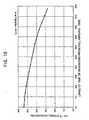
- the decrease of mainspring torque also decreases a swing angle of the balance with hairspring.
- the swing angle of the balance with hairspring is approximately 240 to 270 degrees when the mainspring torque is 25 to 28 g • cm while the swing angle of the balance with hairspring is approximately 180 to 240 degrees when the mainspring torque is 20 to 25 g • cm.
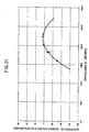
- Fig. 21 there is shown transition of an instantaneous watch error (numeral value indicative of timepiece accuracy) against a swing angle of a balance with hairspring in the conventional representative mechanical timepiece.
- instantaneous watch error refers to "a value representative of fast or slow of a mechanical timepiece at a lapse of one day on the assumption that the mechanical timepiece is allowed to stand for one day while maintaining a state or environment of a swing angle of a balance with hairspring and the like upon measuring a watch error".
- the instantaneous watch error delays when the swing angle of the balance with hairspring is 240 degrees or greater or 200 degrees or smaller.
- the instantaneous watch error is about 0 to 5 seconds per day (about 0 to 5 seconds fast per day) when the swing angle of the balance with hairspring is about 200 to 240 degrees while the instantaneous watch error becomes about -20 seconds per day (about 20 seconds slow per day) when the swing angle of the balance with hairspring is about 170 degrees.
- Fig. 22 there is shown a transition of an instantaneous watch error and a lapse time upon rewinding the mainspring from a full winding state in the conventional representative mechanical timepiece.
- the "watch error" indicative of timepiece advancement per day or timepiece delay per day is shown by an extremely thin line in Fig. 22, which is obtainable by integrating over 24 hours an instantaneous watch error against a lapse time of rewinding the mainspring from the full winding.
- the instantaneous watch error slows down because the mainspring torque decreases and the balance-with-hairspring swing angle decreases as the sustaining time elapses with the mainspring being rewound from a full winding state. Due to this, in the conventional mechanical timepiece, the instantaneous watch error in a mainspring full winding state is previously put forward in expectation of timepiece delay after lapse of a sustaining time of 24 hours, thereby previously adjusting plus the "watch error" representative of timepiece advancement or delay per day.
- the instantaneous watch error in a full winding state is about 3 seconds per day (3 seconds fast per day).
- the instantaneous watch error becomes about -3 seconds per day (about 3 seconds slow per day).
- the instantaneous watch error becomes about -8 seconds per day (about 8 seconds slow per day) .
- the instantaneous watch error becomes about -16 seconds per day (about 16 seconds slow per day).
- a direction of froma center of the mechanical timepiece toward a 12:00 mark on the dial is termed as "12:00 direction”
- a direction of from the center of the mechanical timepiece toward a 3:00 mark on the dial is termed as "3:00 direction”
- a direction of from a center of the mechanical timepiece toward a 6:00 mark on the dial is termed as "6:00 direction”
- a direction of from a center of the mechanical timepiece toward a 9:00 mark on the dial is termed as "9:00 direction” (referring to Fig. 17).
- a position as the 12:00 mark on the dial is up is termed as a "12:00-up position”
- a position as the 3:00 mark on the dial is up is termed as a "3:00-up position”
- a position as the 6:00 mark on the dial is up is termed as a "6:00-up position”
- a position as the 9:00 mark on the dial is up is termed as a "9:00-up position”.
- a “watch error for the mechanical timepiece put in 12:00-up position” is termed as “12-up watch error”
- a “watch error for the mechanical timepiece put in 3:00-up position” is termed as “3-up watch error”
- a “watch error for the mechanical timepiece put in 6:00-up position” is termed as “6-up watch error”
- a “watch error for the mechanical timepiece put in 9:00-up position” is termed as "9-up watch error”.
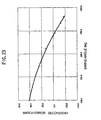
- the average value of watch error in four standing positions is approximately 31 seconds per day. Also, when the swing angle of the balance with hairspring is 250 degrees, the average value of watch error in four standing positions is approximately -4 seconds per day.
- the average value of watch error in four standing positions is approximately 20 to 25 seconds per day.
- the mechanical timepiece when the swing angle of the balance with hairspring is 180 degree has a flat-position watch error of approximately 10 seconds per day. That is, it is to be understood in the mechanical timepiece that the watch error in the standing position is faster by approximately 10 to 15 seconds per day than the watch error in the flat position when the swing angle of the balance with hairspring is 180 degrees.
- Japanese Utility Model Laid-open No. 41675/1979 discloses, as a conventional balance-with-hairspring swing-angle adjusting device, one having a swing-angle adjusting plate generating over-current each time a magnet of the balance with hairspring approaches by swinging and supplying a brake force to the balance with hairspring.
- the present invention is, in a mechanical timepiece structured having a mainspring constituting a power source for the mechanical timepiece, a front train wheel rotating due to rotational force given upon rewinding the mainspring and an escapement/speed-control device for controlling rotation of the front train wheel, the escapement/speed-control device being structured including a balance with hairspring alternately repeating right and left rotation, an escape wheel and pinion rotating based on rotation of the front train wheel and a pallet fork controlling rotation of the escape wheel and pinion based on operation of the balance with hairspring, the mechanical timepiece characterized by comprising: a balance-rotation detector section provided to detect a swing angle of the balance with hairspring by detecting an operating state of the balance with hairspring using light; a position detector section for detecting a position of the mechanical timepiece; and a brake section structured to apply such a force as suppressing rotation of the balance with hairspring to the balance with hairspring based on a signal concerning a position of the mechanical timepiece detected by the position detector section when a swing angle of the
- the balance-rotation detector section is structured so as to preferably include a light emitting part to illuminate a balance arm portion and a light receiving part to receive light illuminated to the balance arm portion.
- the brake section is structured preferably so as to include a coil arranged to damp movement of the balance magnet.
- the swing angle of the balance with hairspring for the mechanical timepiece can be effectively controlled thereby improving accuracy of the mechanical timepiece.
- a mechanical timepiece of the invention preferably comprises a balance-rotation detecting circuit configured to control light emitted by the light emitting part and a balance-rotation control circuit configured to measure operation of the balance arm portion and calculate a swing angle of the balance with hairspring, wherein the balance-rotation control circuit does not energize the coil where a swing angle of the balance with hairspring is smaller than a certain constant threshold, but energizes the coil where a swing angle of the balance with hairspring is the above certain constant threshold or greater.
- a mechanical timepiece of the invention preferably further comprises a power storage section to operate the balance-rotation detecting circuit and the balance-rotation control circuit.
- a mechanical timepiece of the invention preferably further comprises a generator section to charge the power storage section.
- the position detector section preferably includes an oscillating weight, a position detecting member provided on the oscillating weight, and a position detecting electrode for outputting a detection signal to the balance-rotation control circuit by contacting the position detecting member when the mechanical timepiece is in a standing position.
- the position detector section preferably includes an oscillating weight, a position detecting member provided on the oscillating weight, a position detecting electrode for outputting a detection signal to the balance-rotation control circuit by contacting the position detecting member when the mechanical timepiece is in a standing position, a return spring provided not to contact the position detecting member with the position detecting electrode when the mechanical timepiece is in a flat position, and a spherical push member provided to contact the position detecting member with the position detecting electrode when the mechanical timepiece is in a standing position.
- an accurate mechanical timepiece can be provided which is less in change of watch error even after lapse of time from a full winding state.
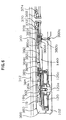
- a movement (mechanical body) 300 of the mechanical timepiece has a main plate 102 structuring a base plate for the movement.
- a hand setting stem 110 is rotatably assembled in a winding-stem guide hole 102a of the main plate 102.
- a dial 104 is attached on the movement 300.
- the hand setting stem 110 has a squared portion and a guide shaft portion.
- a clutch wheel (not shown) is assembled on the square portion of the hand setting stem 110.
- the clutch wheel has a same rotation axis as a rotation axis of the hand setting stem 110. That is, the clutch wheel is provided having a squared hole and rotated based on rotation of the hand setting stem 110 by fitting the squared hole on the squared portion of the hand setting stem 110.
- the clutch wheel has teeth A and teeth B.
- the teeth A are provided in the clutch wheel at an end close to a center of the movement.
- the teeth B are provided in the clutch wheel at an end close to an outside of the movement.
- the movement 300 is provided with a switch device to determine an axial position of the hand setting stem 110.
- the switch device includes a setting lever 190, a yoke 192, a yoke spring 194 and a back holder 196.
- the hand setting stem 110 is determined in rotational axial position based on rotation of the setting lever.
- the clutch wheel is determined in rotation-axis position based on rotation of the yoke.
- the yoke is to be determined at two positions in rotational direction based on rotation of the setting lever.
- a winding pinion 112 is rotatably provided on the guide shaft portion of the hand setting stem 110.
- the winding pinion 112 is structurally rotated through rotation of the clutch wheel.
- a crown wheel 114 is structured to rotate due to rotation of the winding pinion 112.
- a ratchet wheel 116 is structured to rotate due to rotation of the crown wheel 114.
- the movement 300 has as a power source a mainspring 122 accommodated in a barrel complete 120.
- the mainspring 122 is made of an elastic material having springiness, such as iron.
- the mainspring 122 is structured to be wound up to rotation of the ratchet wheel 116.
- a center wheel and pinion 124 is structured for rotation due to rotation of the barrel complete 120.
- a third wheel and pinion 126 is structured rotatable based on rotation of the center wheel and pinion 124.
- a fourth wheel and pinion 128 structured rotatable based on rotation of the third wheel and pinion 126.
- An escape wheel and pinion 130 is structured for rotation due to rotation of the fourth wheel and pinion 128.
- the barrel complete 120, the center wheel and pinion 124, the third wheel and pinion 126 and the fourth wheel and pinion 128 constitute a front train wheel.
- the movement 300 has an escapement/governing device to control rotation of the front train wheel.
- the escapement/governing device includes a balance with hairspring 140 to repeat right and left rotation with a constant period, an escape wheel and pinion 130 to rotate based on rotation of the front train wheel, and pallet fork 142 to control rotation of the escape wheel and pinion 130 based on operation of the balance with hairspring 140.
- the balance with hairspring 140 includes a balance stem 140a, a balance wheel 140b and a stud mainspring 140c.
- Four balance arm portions 140f (referred to as “amida") are provided to couple the balance stem 140a and the balance wheel 140b.
- the number of balance arm portions 140f may be two or three, or four or more.
- the stud mainspring 140c is made of an elastic material having springiness, such as "elinvar". That is, the stud mainspring 140c is made of a metallic conductive material.
- an hour pinion 150 Based on rotation of the center wheel and pinion 124, an hour pinion 150 simultaneously rotates.
- the hour pinion 150 is structured having a minute hand 152 to indicate "minute”.
- the hour pinion 150 is provided with a slip mechanism having predetermined slip torque to the center wheel and pinion 124.
- a minute wheel (not shown) rotates.
- an hour wheel 154 rotates.
- the hour wheel 154 is structured having an hour hand 156 to indicate "hour”.
- the barrel complete 120 is supported for rotation relative to the main plate 102 and barrel bridge 160.
- the center wheel and pinion 124, third wheel and pinion 126, fourth wheel and pinion 128 and escape wheel and pinion 130 are supported for rotation relative to the main plate 102 and train wheel bridge 162.
- the pallet fork 142 is supported for rotation relative to the main plate 102 and pallet fork bridge 164.
- the balance with hairspring 140 is supported for rotation relative to the main plate 102 and balance bridge 166. That is, the balance stem 140a has an upper tenon 140a1 supported for rotation relative to a balance upper bearing 166a fixed on the balance bridge 166.
- the balance upper bearing 166a includes a balance upper hole jewel and a balance upper bridge jewel.
- the balance upper hole jewel and the balance upper bridge jewel are formed of an insulating material such as ruby.
- the balance stem 140a has a lower tenon 140a2 supported for rotation relative to the balance lower bearing 102b fixed on the main plate 102.
- the balance lower bearing 102b includes a balance lower hole jewel and a balance lower bridge jewel.
- the balance lower hole jewel and the balance lower bridge jewel are made of an insulating material such as ruby.
- the stud mainspring 140c is a thin leaf spring in a spiral (helical) form having a plurality of turns.
- the stud mainspring 140c at an inner end is fixed to a stud ball 140d fixed on the balance stem 140a, and the stud mainspring 140c at an outer end is screwed through a stud support 170a attached to a stud support bridge 170 rotatably fixed on the balance bridge 166.
- the balance bridge 166 is made of a metallic conductive material such as brass.
- the stud support bridge 170 is made of a metallic conductive material such as iron.
- the movement 300 has an automatic winding part.
- a ratchet wheel 116 is assembled on a side of a case back of the barrel complete 160.
- the ratchet wheel 116 has a ratchet hole 116a assembled on a squared portion 120b of the barrel stem 120a of the barrel complete 120.
- a ratchet screw 392 fixes the ratchet wheel 116 onto the barrel stem 120a.
- An oscillating weight 360 includes a ball bearing part 362, an oscillating weight member 364 and an oscillating heavy weight 366.
- the ball bearing part 362 includes an inner lace 368, a holding lace 370 and an outer lace 372 so that a plurality of balls 374 are assembled between the inner lace 368 and holding lace 370 and the outer lace 372.
- An oscillating weight pinion 376 is provided on an outer periphery of the outer lace 372.
- a first reduction wheel 380 is rotatably assembled on the barrel bridge 160 and main plate 102.
- the first reduction wheel 380 has a first reduction gear 380a, an upper guide shaft part 380b and a lower guide shaft part 380c.
- the first reduction gear 380a is structured to mesh with the oscillating weight pinion 376.
- An eccentric shaft part 380d is provided on the first reduction wheel 380 at between the first reduction gear 380a and the upper guide shaft part 380b.
- the upper guide shaft part 380b is rotatably supported relative to the barrel bridge 160.
- the lower guide shaft part 380c is rotatably supported relative to the main plate 102.
- a pawl lever 382 is assembled between the first reduction gear 380a and the barrel bridge 160. Consequently, the pawl lever 382 is arranged on a side of the case back of the barrel bridge 160.
- the pawl lever 382 has a push pawl (not shown) and a draw pawl 382c.
- the pawl lever 382 has a guide hole 382a rotatably assembled on the eccentric shaft portion 380d.
- a transmission holder 383 is attached in a position closer to the lower guide shaft part 380c than the eccentric shaft part 380d of the first reduction wheel 380.
- a second reduction wheel and pinion 384 is assembled on the case-back side of the barrel bridge 160 and attached rotatably by a second reduction screw 385.
- the second reduction wheel and pinion 384 has a second reduction gear 384a and a second reduction pinion 384b.
- the second reduction gear 384a is structured in the form of a ratchet gear.
- the push pawl and draw pawl 382c of the pawl lever 382 are in engagement with the ratchet gear 384a.
- the second reduction pinion 384b meshes with the ratchet wheel 116.
- the rotation of the oscillating weight pinion 376 rotates the first reduction wheel 380.
- the pawl lever 382 performs reciprocal motion based on eccentric motion of the eccentric shaft part 380d due to rotation of the first reduction wheel and pinion 380 to rotate the second reduction wheel and pinion 384 through the push pawl and draw pawl 382c in the fixed direction.
- the rotation of the second reduction wheel and pinion 384 rotates the ratchet wheel 116 thereby winding a mainspring 120c in the barrel complete 120.
- a phototransistor 130 is arranged on a balance bridge 166 to illuminate the balance arm portion 140f. That is, the phototransistor 130 constitutes a light emitting part.
- a photodiode 132 is provided on the main plate 102 in order to receive light illuminated to the balance arm portion 140f. That is, the photodiode 132 constitutes a light receiving part.
- the light receiving part is to be constituted, for example, by a photodiode, an optical fiber or a CCD.
- the phototransistor 130 (light emitting part) and the photodiode 132 (light receiving part) constitute a balance-rotation detector section 176.
- a speed control section 144 includes the balance with hairspring 140 and balance magnet 140e.
- the balance magnet 140e will be described in detail later.
- the balance arm portion 140f of the balance with hairspring 140 rotates between the phototransistor 130 and the photodiode 132.
- the balance arm portion 140f positions between the phototransistor 130 and the photodiode 132, the light emitted by the phototransistor 130 is structurally blocked off by the balance arm portion 140f not to be incident on the photodiode 132. Contrary to this, when the balance arm portion 140f is not positioned between the phototransistor 130 and the photodiode 132, the light emitted by the phototransistor 130 structurally reaches the photodiode 132.
- the photodiode 132 is connected to an IC 134.
- the IC 134 includes a balance-rotation detector circuit 172 and a balance-rotation control circuit 306.
- the balance-rotation detector circuit 172 is configured to control light emitted by the phototransistor 130.
- the balance-rotation control circuit 306 is configured to measure the operation of the balance arm portion 140f and calculate a swing angle of the balance with hairspring 140.
- the balance-rotation control circuit 306 previously stores a relationship between a period of light to be incident on the photodiode 132 and a swing angle of the balance with hairspring. Accordingly, the swing angle of the balance with hairspring 140 can be calculated using a period of light incident on the photodiode 132.
- the position detector section 361 is provided to detect whether the position of the mechanical timepiece is in a flat position or a standing position.
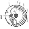
- the position detector section 361 includes an oscillating weight 360, a position detecting member 320 and a position detecting electrode 322.
- the position detecting member 320 is fixed on an outer periphery of the oscillating weight 360.
- the oscillating weight 360 is formed of a metal conductor material.
- the position detecting member 320 is formed of a conductive material.
- the position detecting member 320 is formed of a metal spring material (elastic material) such as stainless steel. In the mechanical timepiece of the invention, is energized through one electrode of a power storage member, plus electrode, main plate, bridge member and oscillating weight 360.
- the case back 312 is fixed on a case member 330.
- the position detecting electrode 322 is provided in an outer-periphery inner surface of the case back 312 through an insulating part.
- the position detecting electrode 322 is provided throughout the outer-periphery inner surface of the case back 312 through the insulating part (over 360 degrees with reference to a timepiece center).
- the position detecting electrode 322 is out of conduction to the case back 312 and hence out of conduction to the case member 322. Also, the position detecting electrode 322 is out of conduction to the main plate 102, out of conduction to the bridge member 160, 166 and out of conduction to the oscillating weight 360.
- a position detecting weight 320w is attached to a tip of the position detecting member 320.
- By changing the position of attaching the position detecting weight 320w on the position detecting member 320 and/or changing the mass of the position detecting weight 320w changed is a positional condition of the mechanical timepiece that the position detecting member 320 is to be contacted with the position detecting electrode 322. That is, by changing the position of attaching the position detecting weight 320w on the position detecting member 320 and/or changing the mass of the position detecting weight 320w, it is possible to change the condition under which determination is made whether in a flat position or a standing position of the mechanical timepiece that the position detecting member 320 is to be contacted with the position detecting electrode 322.
- the position detecting electrode 322 is connected to the balance-rotation control circuit 306.
- the position detecting member 320 contacts the position detecting electrode 322, the position detecting electrode 322 is put in conduction to the plus electrode so that a signal of standing position detection is inputted to the balance-rotation control circuit 306.
- a critical angle of contacting the position detecting member 320 with the position detecting electrode 322 is determined by properly selecting an elastic coefficient of the position detecting member 320 and an attaching position or mass of the position detecting weight 320w, making it possible to detect whether the mechanical timepiece is placed in a flat position or a standing position.
- the position detecting member 320 when the mechanical timepiece is placed slant at an angle of from a flat position to the critical angle, the position detecting member 320 is structured not to contact the position detecting member 320 with the position detecting electrode 322, while when the mechanical timepiece is placed slant at an angle of from a standing position to the critical angle, the position detecting member 320 may be structured to contact the position detecting member 320 with the position detecting electrode 322.
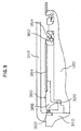
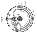
- a position detecting member 342 is provided at an outer periphery of the oscillating weight 360.
- the position detecting member 342 is guided at an inside of a guide member 338, which is structured to protrude from the outer periphery of the oscillating weight 360 due to a mass of a spherical press member 340.
- the position detecting member 342, the guide member 338 and the spherical press member 340 are formed of a metal material such as stainless steel.
- the position detecting member 342 is in electric conduction to one electrode of a power storage member, plus electrode through the main plate, bridge member and oscillating weight 360.
- a return spring 344 for pushing back the position detecting member 342 from the outer periphery toward a center of the oscillating weight 360 is provided inside the guide member 338.
- a case back 312 is fixed on a case member 330.
- a position detecting electrode 322 is provided in an outer-periphery inner side of the case back 312 through an insulating part. The position detecting electrode 322 is provided throughout the outer-periphery inner side of the case back 312 through the insulating part (over 360 degrees with reference to a center of the timepiece).
- the position detecting member 320 contacts the position detecting electrode 322, the position detecting electrode 322 is put in conduction to the plus electrode.
- a signal of standing position detection is inputted to the balance-rotation control circuit 306.
- This structure also makes it possible to accurately detect whether the mechanical timepiece is placed in a flat position or a standing position.
- a critical angle of contacting the position detecting member 342 with the position detecting electrode 322 is determined by properly selecting a spring constant of the return spring 344 and a mass of the spherical press member 340, making it possible to detect whether the mechanical timepiece is placed in a flat position or a standing position.
- the spherical press member 340, position detecting member 342 and return spring 344 are structured not to contact the position detecting member 342 with the position detecting electrode 322 when the mechanical timepiece is placed slant at an angle of between a flat position to the critical angle, and the spherical press member 340, position detecting member 342 and return spring 344 are structured to contact the position detecting member 342 with the position detecting electrode 322 when the mechanical timepiece is placed slant at an angle of between a standing position to the critical angle.
- a secondary battery 136 for operating the IC 134 is fixed to the main plate 102.
- the secondary battery 136 constitutes a power storage section 137. That is, the power storage section 137 constitutes a power source to operate the IC 134.
- the power storage section 137 may be structured by a secondary battery or a capacitor. Or otherwise, a primary battery may be utilized in place of the power storage section 137.
- a generator section 150 is provided in order to charge the secondary battery 136 of the power storage section 137.
- the generator section 150 may be a manual-winding generator mechanism to generate voltage due to rotation of the hand setting stem 102 or an automatic-winding generator mechanism to generate voltage due to rotation of an oscillating weight.
- the generator section 150 may be arranged on a "back side” of the movement 300 or on a “front side” of the movement 300.
- the structure for the generator section 150 may use a similar one to the conventional structure and hence is not illustrated in Fig. 1.
- the generator section 150 includes a winding mechanism 152 to operate due to rotation of the hand setting stem 102, a speed-up train wheel 154 to increase the speed and deliver rotation of the winding mechanism 152, a rotor 156 to rotate due to rotation of the speed-up train wheel 154, a stator 157 having a rotor hole opposed to the rotor magnet of the rotor 156, a generator coil 158 to generate electromotive force due to rotation of the rotor 156 and a rectifier circuit 160 to rectify a current caused on the generator coil 158.
- the current rectified by the rectifier circuit 160 flows to the secondary battery 136 constituting the power storage section 137.
- a capacitor may be employed in place of the secondary battery 136.
- the rectification operation by the rectifier circuit 160 may be half-wave rectification or full-wave rectification.
- the rectifier circuit may be built in the IC 134 or provided separate from the IC 134.
- the generator section When the generator section is structured by an automatic winding generator mechanism, the generator section includes an oscillating weight, a speed-up train wheel to increase and deliver rotation of the oscillating weight, a rotor to rotate due to rotation of the speed-up train wheel, a stator having a rotor hole opposed to the rotor magnet of the rotor, a generator coil to generate electromotive force due to rotation of the rotor and a rectifier circuit to rectify the current caused on the generator coil.
- the current rectified by the rectifier circuit structurally flows to the secondary battery 136.
- the mechanical timepiece of the invention has the oscillating weight 360, and accordingly the generator section can be structured by an automatic winding generator mechanism.
- electronic wrist watch with generator device are disclosed in Japanese Patent Laid-open No. 266989/1986 and Japanese Patent Laid-open No. 293143/1986, and a portable timepiece with charge function is disclosed in Japanese Patent Laid-open No. 288192/1986.
- Coils 180a, 180b are attached on a front surface of the main plate 102 in a manner facing to a surface of a balance wheel 140b close to the main plate.
- the coils 180a, 180b constitute a control section 146.
- the number of coils is, for example, two as shown in Fig. 1 to Fig. 4 but may be one, two, three or four or more.
- Abalance magnet 140e is attached on a surface of the balance wheel 140b close to the main plate in a manner facing to a front surface of the main plate 102.
- the circumferential interval of the coils 180a, 180b where the coils 180a, 180b are provided in plurality is preferably an integer multiple of a circumferential interval of the S and N poles of the balance magnet 140e arranged opposed to the coils 180a, 180b.
- the interval is not circumferentially same for all the coils.
- the respective interconnections between the coils are preferably connected in series not to mutually cancel the current caused on each coil due to electromagnetic induction. Or otherwise, the respective interconnections between the coils may be connected in parallel not to mutually cancel the current caused on each coil due to electromagnetic induction.
- the balance magnet 140e has an annular (ring-formed) shape and is alternately provided, along a circumferential direction, with magnet portions constituted, for example, by twelve S poles 140s1 - 140s12 and twelve N poles 140n1 - 140n12 that are vertically polarized.
- the number of magnet portions arranged annular (in a ring form) in the balance magnet 140e in the example shown in Fig. 5 is twelve, it may be in a plurality of two or more.
- a gap is provided between the balance magnet 140e and the coil 180a, 180b.
- the gap between the balance magnet 140e and the coil 180a, 180b is determined such that the balance magnet 140e has a magnetic force capable of giving effects upon the coil 180a, 180b when the coil 180a, 180b is energized.
- the balance magnet 140e is fixed, for example, through adhesion to the main-plate-side surface of the balance wheel 140b in such a state that one surface is in contact with a ring rim of the balance wheel 140b and the other surface facing to the front surface of the main plate 102.
- a first lead wire 182 is provided to connect between one terminal of the coil 180a and a first coil terminal of the IC 134.
- a second lead wire 184 is provided to connect between one terminal of the coil 180b and a second coil terminal of the IC 134.
- the stud mainspring 140c has a thickness (radial thickness of the balance with hairspring) of 0.021 millimeter, for example.
- the balance magnet 140e has, for example, an outer diameter of approximately 9 millimeters, an inner diameter of approximately 7 millimeters, a thickness of approximately 1 millimeter and a magnetic flux density of approximately 0.02 tesla.
- the coil 180a, 180b respectively has the number of turns, for example, of 8 turns and a coil diameter of approximately 25 micrometers.
- the gap between the balance magnet 140e and the coil 180a, 180b is, for example, approximately 0.4 millimeter.
- the stud mainspring 140c expands and contracts radially of the stud mainspring 140c depending on an angle of rotation of the balance with hairspring 140. For example, in a state shown in Fig. 3, when the balance with hairspring 140 rotates clockwise, the stud mainspring 140c contracts in a direction toward a center of the balance with hairspring 140. Contrary to this, when the balance with hairspring 140 rotates counterclockwise, the stud mainspring 140c expands in a direction away from the center of the balance with hairspring 140.
- the coils 180a, 180b are structurally not energized by operation of the balance-rotation control circuit 306.
- the coils 180a, 180b are energized by operation of the balance-rotation control circuit 306 to exert to the balance with hairspring 140 such a force as suppressing rotational motion of the balance with hairspring 140 due to an induction current caused by change of magnetic flux on the balance magnet 140e. Due to the action of the balance-rotation control circuit 306 and coils 180a, 180b and balance magnet 140e, a brake force suppressing the rotation of the balance with hairspring 140 is structurally applied to the balance with hairspring 140 thereby reducing the swing angle of the balance with hairspring 140.
- the balance-rotation control circuit 306 structurally operates not to energize the coils 180a, 180b. Accordingly, in a range that the swing angle exceeds 0 degree and in a range of less than 180 degrees, the coils 180a, 180b are not energized. Thus, the balance with hairspring 140 is not applied by such a force as suppressing rotation motion of the balance with hairspring 140.
- the operation of the balance-rotation detecting circuit 172 starts detection of rotation of the balance with hairspring (step S31).
- the balance-rotation detecting circuit 172 determines a detection time for detecting a swing angle of the balance with hairspring (step S32). Determination of a detection time for detecting the swing angle of the balance with hairspring is made, e.g. by a counter. The set time for detecting rotation of the balance with hairspring is previously stored in the balance-rotation detecting circuit 172.
- the set time for performing rotation detection of the balance with hairspring is, for example, about one hour.
- the set time for detecting rotation of the balance with hairspring is preferably approximately 0.25 to 6 hours, more preferably approximately 0.5 to 3 hours, further preferably approximately 1 to 2 hours.
- the balance-rotation detecting circuit 172 determines a lapse of the set time
- the balance-rotation detecting circuit 172 turns on the phototransistor 130 (step S33). If the balance-rotation detecting circuit 172 determines that the set time has not been elapsed, the process returns to the step S32 to repeat operation for determining a set time.
- step S33 when the balance-rotation detecting circuit 172 turns on the phototransistor 130, the balance-rotation control circuit 306 measures an operating state of the balance arm portion 140f by use of light to be incident on the photodiode 132, thereby calculating a swing angle of the balance with hairspring 140.
- the balance-rotation control circuit 306 previously stores a relationship between a period of light to be incident on the photodiode 132 and a swing angle of the balance with hairspring. Accordingly, calculation of a swing angle of the balance with hairspring 140 is made by using a period of light to be incident on the photodiode 132.
- the balance-rotation control circuit 306 determines that the swing angle of the balance with hairspring 140 is greater than a set angle, the balance-rotation detecting circuit 172 turns off the phototransistor 130 (step S35).
- the balance-rotation control circuit 306 detects a position of the mechanical timepiece (step S38) and determines whether the mechanical timepiece is in a standing position or a flat position (step S39).
- the balance-rotation control circuit 306 detects a presence or absence of a signal representative of a standing position outputted by the position detecting electrode 322 when the position detecting member 320 contacts the position detecting electrode 322, and detects whether the mechanical timepiece is in a standing position or a flat position.
- the balance-rotation control circuit 306 is structured to determine that the mechanical timepiece is in a vertical state if a signal representative of a standing position is outputted through the position detecting electrode 322 for a threshold of a constant detection time, e.g. outputted for consecutive 5 seconds, and determine that the mechanical timepiece is in a horizontal state if a signal representative of a standing position is not outputted through the position detecting electrode 322 for a threshold of a constant detection time, e.g. not continuously outputted for 5 seconds.
- the balance-rotation control circuit 306 structurally determines that the mechanical timepiece is in a standing position when the position detecting electrode 322 first outputs a signal representative of a standing position, and that the mechanical timepiece is in a flat position when the position detecting electrode 322 does not first output a signal representative of a standing position.
- a limitation-time threshold for the determination 3 it is preferred to set a limitation-time threshold for the determination 3 to 4 times as great as a threshold of a detection time for which the signals are consecutively outputted by the position detecting electrode 322.
- a position of the mechanical timepiece can be positively detected while excluding affection on the position detecting electrode 322 due to chattering.of the position detecting member 320.
- the balance-rotation control circuit 306 energize the coils 180a, 180b by an operating condition of flat state (step S40).
- the energization of the coils 180a, 180b generates an induction current due to change of the magnetic flux on the balance magnet 140e and exerts such a force as suppressing the rotational motion of the balance with hairspring 140.
- the swing angle of the balance with hairspring 140 is decreased by application of a brake force suppressing rotation of the balance with hairspring 140 to the balance with hairspring 140.
- the operating condition of flat position for energizing the coils 180a, 180b by the balance-rotation control circuit 306 and decreasing the swing angle of the balance with hairspring 140 is preferably determined by experiments and stored in the balance-rotation control circuit 306.
- the balance-rotation control circuit 406 energizes the coils 180a, 180b by the operating condition of standing position (step S41).
- the energization of the coils 180a, 180b generates an induction current due to change of the magnetic flux on the balance magnet 140e and exerts such a force as suppressing rotational motion of the balance with hairspring 140 to the balance with hairspring 140.
- the swing angle of the balance with hairspring 140 is decreased by applying to the balance with hairspring 140 a brake force of suppressing rotation of the balance with hairspring 140.
- the operating condition of standing position for energizing the coils 180a, 180b by the balance-rotation control circuit 306 and decreasing the swing angle of the balance with hairspring 140 also is preferably determined by experiments and stored in the balance-rotation control circuit 306.
- the balance-rotation control circuit 306 determines a time for detecting a position the mechanical timepiece is placed (step S42).
- the determination of a detection time for detecting a position is made, for example, by a counter.
- the set time for position detection is previously stored in the balance-rotation control circuit 406.
- the set time for detecting a position the mechanical timepiece is placed is, for example, approximately 10 minutes.
- the set time for position detection is preferably approximately 1 to 60 minutes, more preferably approximately 5 to 30 minutes, and further preferably approximately 10 to 15 minutes.
- the set time for detecting a position the mechanical timepiece is placed is set smaller than a set time for detecting rotation of the balance with hairspring stated before.
- the set time for detecting rotation of the balance with hairspring is preferably 1 hour.
- the balance-rotation detecting circuit 172 again determines a time for detecting a swing angle of the balance with hairspring (step S43).
- the detection time determination of a balance-with-hairspring swing angle is made, for example, by a counter.
- the set time for detecting rotation of the balance with hairspring is previously stored in the balance-rotation detecting circuit 172.
- the set time for detecting rotation of the balance with hairspring is, for example, approximately 1 hour.
- the set time for detecting rotation of the balance with hairspring is the same as the set time stated before.
- the process returns to the step S42. Repeated is an operation of determining a detection time for position detection.
- the process returns to the step S33.
- the process returns to the step S58.
- the relationship between a time for energizing the coils 180a, 180b by the balance-rotation control circuit 306 and a swing angle of the balance with hairspring 140 is previously determined by experiments and a result thereof is stored in the balance-rotation control circuit 306.
- the set angle of a swing angle of the balance with hairspring 140 is previously stored in the balance-rotation control circuit 406.
- the set angle of a swing angle of the balance with hairspring 140 is, for example, 180 degrees.
- the set angle of a swing angle of the balance with hairspring 140 is preferably 150 to 210 degrees.
- step S34 if the balance-rotation control circuit 306 determines that the swing angle of the balance with hairspring 140 is smaller than the set angle, the balance-rotation detecting circuit 272 turns off the operation of applying voltage to the electrostatic capacitor portion (step S36). In this case, the balance-rotation control circuit 306 does not energize the coils 180a, 180b (step S37).
- the mechanical timepiece of the invention can accurately and efficiently control the swing angle of the balance with hairspring 140.
- circuits for various functions may be configured within the IC and the IC may be a PLA-IC built with a program for various operations.
- external elements such as resistors, capacitors, coils, diodes and transistors, can be used as required together with the IC.
- the present invention is, in a mechanical timepiece structured as stated above having a balance with hairspring that an escape/speed-control device repeats right and left rotation, an escape wheel and pinion rotating based on rotation of a front train wheel, and a pallet fork to control rotation of the escape wheel and pinion based on operation of the balance with hairspring, structured having a position detector section to detect a position of the mechanical timepiece, a balance-rotation detector section to detect a swing angle of the balance with hairspring, and a brake section to control an rotation angle of the balance with hairspring, it is possible to improve the accuracy of the mechanical timepiece without reducing the sustaining time for the mechanical timepiece.
- an eye is put on a relationship between an instantaneous watch error and a swing angle to keep the swing angle, thereby suppressing the change of the instantaneous watch error and adjusting to reduce an advance and delay per day of the timepiece.
- the swing angle varies with lapse of time due to a relationship between a sustaining time and a swing angle.
- instantaneous watch error varies with lapse of time due to a relationship between a swing angle and an instantaneous watch rate. Due to this, it has been difficult to prolong a sustaining time of the timepiece capable of maintaining constant accuracy.
- the flat-position watch error in a full winding state of the mainspring is approximately 23 seconds per day (approximately 23 seconds fast per day) and the standing-position watch error is approximately 18 seconds per day (approximately 18 seconds fast per day).
- the flat-position watch error is approximately 17 seconds per day (approximately 17 seconds fast per day) and the standing-position watch error is approximately 13 seconds per day (approximately 13 seconds fast per day)
- the standing-position watch error is approximately -2 seconds per day (approximately 2 seconds slow per day) and the flat-position watch error is approximately -3 seconds per day (approximately 3 seconds slow per day).
- the instantaneous watch error can be maintained approximately 5 seconds per day (maintaining a state of approximately 5 seconds fast per day) in a state the brake section is in operation, i.e. before lapse of 27 hours from the full winding state of the mainspring.
- the instantaneous watch error is approximately -2 seconds slow per day (approximately 2 seconds slow per day).
- the mechanical timepiece having the balance-rotation angle control mechanism of the invention suppresses the timepiece instantaneous watch error from varying due to control on the swing angle of the balance with hairspring, it is possible to increase the lapse time from the full winding state in which the instantaneous watch error is approximately 0 to 5 seconds per day as compared to a conventional mechanical timepiece shown by an extreme thin line in Fig. 22.
- the mechanical timepiece of the invention has a sustaining time of approximately 32 hours in which the instantaneous watch error is within approximately plus/minus 5 seconds per day.
- This sustaining time value is approximately 1.45 times as long as a sustaining time of approximately 22 hours of the conventional mechanical timepiece wherein the instantaneous watch error is approximately within plus/minus 5 seconds per day.
- the control of swing angle of the balance with hairspring in the thus-structured mechanical timepiece of the invention is made in consideration of a position of the mechanical timepiece.
- the mechanical timepiece of the present invention obtained a result of simulation that accuracy is well as compared to the conventional mechanical timepiece.
- the mechanical timepiece of the present invention has a simple structure and is suited for realizing an extreme accurate mechanical timepiece.
- the mechanical timepiece of the invention has a position detector section to detect a position of the mechanical timepiece and an optical detecting type of a balance-rotation detector section to detect a swing angle of a balance with hairspring, manufacture of a mechanical timepiece and watch error adjustment are extremely easy.
Landscapes
- Physics & Mathematics (AREA)
- General Physics & Mathematics (AREA)
- Engineering & Computer Science (AREA)
- Electromagnetism (AREA)
- Power Engineering (AREA)
- Electromechanical Clocks (AREA)
- Electric Clocks (AREA)
Abstract
In a mechanical timepiece of the present invention, a
movement 300 includes a barrel complete 120, a center wheel and
pinion 124, a third wheel and pinion 126, a fourth wheel and
pinion 128, a balance with hairspring 140, an escape wheel and
pinion 130 and a pallet fork 142. Coils 180a, 180b are attached
on a front surface of a main plate 102 in a manner facing a surface
of a balance wheel 140b close to the main plate. A balance magnet
140e is attached on a surface of the balance wheel 140b close
to the main plate in a manner facing a front surface of the main
plate 102.
The mechanical timepiece of the invention has a
balance-rotation detector section 176 provided to detect a swing
angle of the balance with hairspring by detecting an operating
state of the balance with hairspring 140 using light, a position
detector section 361 to detect a position of the mechanical
timepiece, and a brake section 146 structured to apply to the
balance with hairspring 140 such a force as suppressing rotation
of the balance with hairspring 140 based on a signal concerning
a position of the mechanical timepiece detected by the position
detector section 361 when a swing angle of the balance with
hairspring 140 detected by the balance-rotation detector section
176 is equal to or greater than a previously-set set angle.
Description
- The present invention relates to a mechanical timepiece having a position detector section and optical balance-rotation detector section, which is structured for applying such a force as suppressing rotation of the balance with hairspring based on a detection result of detecting a position a mechanical is placed and a detection result of a swing angle of a balance with hairspring of the mechanical timepiece.
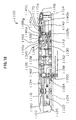
- In the conventional mechanical timepiece, as shown in Fig. 17 and Fig. 18 the mechanical-timepiece movement 1100 (mechanical body) has a
main plate 1102 constituting a base plate for the movement. Ahand setting stem 1110 is rotatably assembled in a hand-setting-stem guide hole 1102a of themain plate 1102. A dial 1104 (shown by the virtual line in Fig. 18) is attached to themovement 1100. - Generally, of the both sides of a main plate, the side having a dial is referred to as a "back side" of the movement and the opposite side to the side having the dial as a "front side". The train wheel assembled on the "front side" of the movement is referred to as a "front train wheel" and the train wheel assembled on the "back side" of the movement is as a "back train wheel".
- The
hand setting stem 1110 is determined in axial position by a switch device including asetting lever 1190, ayoke 1192, ayoke spring 1194 and aback holder 1196. A windingpinion 1112 is rotatably provided on a guide axis portion of thehand setting stem 1110. When rotating thehand setting stem 1110 in a state thehand setting stem 1110 is in a first hand-setting-stem position closest to an inward of the movement along a rotation axis direction (0 stage), the windingpinion 1112 rotates through rotation of the clutch wheel. Acrown wheel 1114 rotates due to rotation of the windingpinion 1112. Aratchet wheel 1116 rotates due to rotation of thecrown wheel 1114. By rotating theratchet wheel 1116, amainspring 1122 accommodated in a barrel complete 1120 is wound up. A center wheel andpinion 1124 rotates due to rotation of the barrel complete 1120. An escape wheel andpinion 1130 rotates through rotation of a fourth wheel andpinion 1128, third wheel andpinion 1126 and center wheel andpinion 1124. The barrel complete 1120, center wheel andpinion 1124, third wheel andpinion 1126 and fourth wheel andpinion 1128 constitutes a front train wheel. - An escapement/speed-control device for controlling rotation of the front train wheel includes a balance with
hairspring 1140, an escape wheel andpinion 1130 andpallet fork 1142. The balance withhairspring 1140 includes abalance stem 1140a, a balance wheel 1140b and astud mainspring 1140c. Based on rotation of the center wheel andpinion 1124, anhour pinion 1150 rotates simultaneously. Aminute hand 1152 attached on thehour pinion 1150 indicates "minute". Thehour pinion 1150 is provided with a slip mechanism for the center wheel andpinion 1124. Based on rotation of thehour pinion 1150, anhour wheel 1154 rotates through rotation of a minute wheel. Anhour hand 1156 attached on thehour wheel 1154 indicates "hour". - The barrel complete 1120 is rotatably supported relative to the
main plate 1102 and abarrel bridge 1160. The center wheel andpinion 1124, the third wheel andpinion 1126, the fourth wheel andpinion 1128 and the escape wheel andpinion 1130 are rotatably supported relative to themain plate 1102 and atrain wheel bridge 1162. Thepallet fork 1142 is rotatably supported relative to themain plate 1102 and apallet fork bridge 1164. The balance withhairspring 1140 is rotatably supported relative to themain plate 1102 and abalance bridge 1166. - The
stud mainspring 1140c is a thin leaf spring in a spiral (helical) form having a plurality of turns. Thestud mainspring 1140c at an inner end is fixed to astud ball 1140d fixed on thebalance stem 1140a, and thestud mainspring 1140c at an outer end is fixed by screwing through astud support 1170a attached to astud support bridge 1170 fixed on thebalance bridge 1166. - A
regulator 1168 is rotatably attached on thebalance bridge 1166. A stud bridge 1168a and a stud rod 1168b are attached on theregulator 1168. Thestud mainspring 1140c has a portion close to the outer end positioned between the stud bridge 1168a and the stud rod 1168b. - Generally, in the conventional representative mechanical timepiece, as shown in Fig. 19 the torque on the mainspring decreases while being rewound as the sustaining time elapses from a state the mainspring is fully wound (full winding state). For example, in the case of Fig. 19, the mainspring torque in the full winding state is about 27 g • cm, which becomes about 23 g • cm at a lapse of 20 hours from the full winding state and about 18 g • cm at a lapse of 40 hours from the full winding state.
- Generally, in the conventional representative mechanical timepiece, as shown in Fig. 20 the decrease of mainspring torque also decreases a swing angle of the balance with hairspring. For example, in the case of Fig. 20, the swing angle of the balance with hairspring is approximately 240 to 270 degrees when the mainspring torque is 25 to 28 g • cm while the swing angle of the balance with hairspring is approximately 180 to 240 degrees when the mainspring torque is 20 to 25 g • cm.
- Referring to Fig. 21, there is shown transition of an instantaneous watch error (numeral value indicative of timepiece accuracy) against a swing angle of a balance with hairspring in the conventional representative mechanical timepiece. Here, "instantaneous watch error" refers to "a value representative of fast or slow of a mechanical timepiece at a lapse of one day on the assumption that the mechanical timepiece is allowed to stand for one day while maintaining a state or environment of a swing angle of a balance with hairspring and the like upon measuring a watch error". In the case of Fig. 21, the instantaneous watch error delays when the swing angle of the balance with hairspring is 240 degrees or greater or 200 degrees or smaller.
- For example, in the conventional representative mechanical timepiece, as shown in Fig. 21 the instantaneous watch error is about 0 to 5 seconds per day (about 0 to 5 seconds fast per day) when the swing angle of the balance with hairspring is about 200 to 240 degrees while the instantaneous watch error becomes about -20 seconds per day (about 20 seconds slow per day) when the swing angle of the balance with hairspring is about 170 degrees.
- Referring to Fig. 22, there is shown a transition of an instantaneous watch error and a lapse time upon rewinding the mainspring from a full winding state in the conventional representative mechanical timepiece. Here, in the conventional mechanical timepiece, the "watch error" indicative of timepiece advancement per day or timepiece delay per day is shown by an extremely thin line in Fig. 22, which is obtainable by integrating over 24 hours an instantaneous watch error against a lapse time of rewinding the mainspring from the full winding.
- Generally, in the conventional mechanical timepiece, the instantaneous watch error slows down because the mainspring torque decreases and the balance-with-hairspring swing angle decreases as the sustaining time elapses with the mainspring being rewound from a full winding state. Due to this, in the conventional mechanical timepiece, the instantaneous watch error in a mainspring full winding state is previously put forward in expectation of timepiece delay after lapse of a sustaining time of 24 hours, thereby previously adjusting plus the "watch error" representative of timepiece advancement or delay per day.
- For example, in the conventional representative mechanical timepiece, as shown by an extreme thin line in Fig. 22 the instantaneous watch error in a full winding state is about 3 seconds per day (3 seconds fast per day). However, when 20 hour elapses from the full winding state, the instantaneous watch error becomes about -3 seconds per day (about 3 seconds slow per day). When 24 hours elapses from the full winding state, the instantaneous watch error becomes about -8 seconds per day (about 8 seconds slow per day) . When 30 hours elapses from the full winding state, the instantaneous watch error becomes about -16 seconds per day (about 16 seconds slow per day).
- In the mechanical timepiece, when assuming a state attaching a dial, definition is given for "flat position" as the dial is horizontal and "standing position (vertical position)" as the dial is vertical.
- Also, in the mechanical timepiece, when assuming a state of attaching a dial, a direction of froma center of the mechanical timepiece toward a 12:00 mark on the dial is termed as "12:00 direction", a direction of from the center of the mechanical timepiece toward a 3:00 mark on the dial is termed as "3:00 direction", a direction of from a center of the mechanical timepiece toward a 6:00 mark on the dial is termed as "6:00 direction", and a direction of from a center of the mechanical timepiece toward a 9:00 mark on the dial is termed as "9:00 direction" (referring to Fig. 17).
- Also, in the mechanical timepiece, when assuming a state that a dial is mounted and the dial is vertical, a position as the 12:00 mark on the dial is up is termed as a "12:00-up position", a position as the 3:00 mark on the dial is up is termed as a "3:00-up position", a position as the 6:00 mark on the dial is up is termed as a "6:00-up position", and a position as the 9:00 mark on the dial is up is termed as a "9:00-up position".
- It is known in the mechanical timepiece that measurement value of "watch error" is different between the four standing positions of "12:00-up position", "3:00-up position", "6:00-up position" and "9:00-up position". Consequently, in the mechanical timepiece, "watch error" is measured in four standing positions. Watch error adjustment of the mechanical timepiece is conducted such that the respective measurement values of "watch error" meet the required rating, thus manufacturing a mechanical timepiece.
- In the below explanations, a "watch error for the mechanical timepiece put in 12:00-up position" is termed as "12-up watch error", a "watch error for the mechanical timepiece put in 3:00-up position" is termed as "3-up watch error", a "watch error for the mechanical timepiece put in 6:00-up position" is termed as "6-up watch error", and a "watch error for the mechanical timepiece put in 9:00-up position" is termed as "9-up watch error".
- Referring to Fig. 23, in the mechanical timepiece, when the swing angle of the balance with hairspring is 150 degrees, the average value of watch error in four standing positions (average value of 3-up watch error, 6-up watch error, 9-up watch error and 12-up watch error) is approximately 31 seconds per day. Also, when the swing angle of the balance with hairspring is 250 degrees, the average value of watch error in four standing positions is approximately -4 seconds per day.
- In the mechanical timepiece, when the swing angle of the balance with hairspring is 180 degrees, the average value of watch error in four standing positions is approximately 20 to 25 seconds per day.
- On the contrary, referring to Fig. 20, the mechanical timepiece when the swing angle of the balance with hairspring is 180 degree has a flat-position watch error of approximately 10 seconds per day. That is, it is to be understood in the mechanical timepiece that the watch error in the standing position is faster by approximately 10 to 15 seconds per day than the watch error in the flat position when the swing angle of the balance with hairspring is 180 degrees.
- Conventionally, the adjustment of watch error for such a mechanical timepiece has been made by manually removing the balance with
hairspring 1140 from a movement (mechanical body) 1100 of a mechanical timepiece once assembled, manually grinding out part of a balance wheel and again assembling the balance withhairspring 1140 in the movement (mechanical body) 1100. Due to this, watch error was first measured in the movement (mechanical body) of the mechanical timepiece once assembled and part of the balance wheel is ground out, and thereafter watch error was measured in the movement (mechanical member) 1100 on which the balance withhairspring 1140 was reassembled. - Accordingly, conventionally, measurement and adjustment for watch error has taken much time and labor thus making it difficult to realize an accurate mechanical timepiece.
- Incidentally, for example, Japanese Utility Model Laid-open No. 41675/1979 discloses, as a conventional balance-with-hairspring swing-angle adjusting device, one having a swing-angle adjusting plate generating over-current each time a magnet of the balance with hairspring approaches by swinging and supplying a brake force to the balance with hairspring.
- Also, a concrete structure of a conventional automatic-timepiece automatic device mechanism is disclosed, for example, in Japanese Patent Laid-open No. 183645/1999.
- It is an object of the present invention to provide an accurate mechanical timepiece, which is less in change of watch error even after lapse of time from a full winding state.
- The present invention is, in a mechanical timepiece structured having a mainspring constituting a power source for the mechanical timepiece, a front train wheel rotating due to rotational force given upon rewinding the mainspring and an escapement/speed-control device for controlling rotation of the front train wheel, the escapement/speed-control device being structured including a balance with hairspring alternately repeating right and left rotation, an escape wheel and pinion rotating based on rotation of the front train wheel and a pallet fork controlling rotation of the escape wheel and pinion based on operation of the balance with hairspring, the mechanical timepiece characterized by comprising: a balance-rotation detector section provided to detect a swing angle of the balance with hairspring by detecting an operating state of the balance with hairspring using light; a position detector section for detecting a position of the mechanical timepiece; and a brake section structured to apply such a force as suppressing rotation of the balance with hairspring to the balance with hairspring based on a signal concerning a position of the mechanical timepiece detected by the position detector section when a swing angle of the balance with hairspring detected by the balance-rotation detector section is greater than a preset set angle.
- In a mechanical timepiece of the invention, the balance-rotation detector section is structured so as to preferably include a light emitting part to illuminate a balance arm portion and a light receiving part to receive light illuminated to the balance arm portion.
- Also, in a mechanical timepiece of the invention, the brake section is structured preferably so as to include a coil arranged to damp movement of the balance magnet.
- By using the position detector section, balance-rotation detector section and brake section thus structured, the swing angle of the balance with hairspring for the mechanical timepiece can be effectively controlled thereby improving accuracy of the mechanical timepiece.
- Also, a mechanical timepiece of the invention preferably comprises a balance-rotation detecting circuit configured to control light emitted by the light emitting part and a balance-rotation control circuit configured to measure operation of the balance arm portion and calculate a swing angle of the balance with hairspring, wherein the balance-rotation control circuit does not energize the coil where a swing angle of the balance with hairspring is smaller than a certain constant threshold, but energizes the coil where a swing angle of the balance with hairspring is the above certain constant threshold or greater.
- Also, a mechanical timepiece of the invention preferably further comprises a power storage section to operate the balance-rotation detecting circuit and the balance-rotation control circuit.
- Also, a mechanical timepiece of the invention preferably further comprises a generator section to charge the power storage section.
- Furthermore, in a mechanical timepiece of the invention, the position detector section preferably includes an oscillating weight, a position detecting member provided on the oscillating weight, and a position detecting electrode for outputting a detection signal to the balance-rotation control circuit by contacting the position detecting member when the mechanical timepiece is in a standing position.
- Furthermore, in a mechanical timepiece of the invention, the position detector section preferably includes an oscillating weight, a position detecting member provided on the oscillating weight, a position detecting electrode for outputting a detection signal to the balance-rotation control circuit by contacting the position detecting member when the mechanical timepiece is in a standing position, a return spring provided not to contact the position detecting member with the position detecting electrode when the mechanical timepiece is in a flat position, and a spherical push member provided to contact the position detecting member with the position detecting electrode when the mechanical timepiece is in a standing position.
- By thus structuring, an accurate mechanical timepiece can be provided which is less in change of watch error even after lapse of time from a full winding state.
-
- Fig. 1 is a plan view showing a schematic form on a front side of a movement, when an automatic device part is removed, in an embodiment of a mechanical timepiece of the present invention (in Fig. 1, parts such as the automatic device part are partly omitted and bridge members are shown by virtual lines).
- Fig. 2 is a magnified fragmentary sectional view showing a schematic form of a train wheel and escapement/speed-control section in the embodiment of the mechanical timepiece of the invention.
- Fig. 3 is a magnified fragmentary plan view showing a schematic form of a balance with hairspring part in the embodiment of the mechanical timepiece of the invention.
- Fig. 4 is a magnified fragmentary sectional view showing a schematic form of the balance with hairspring part in the embodiment of the mechanical timepiece of the invention.
- Fig. 5 is a perspective view showing a schematic form of a balance magnet used in the mechanical timepiece of the invention.
- Fig. 6 is a magnified fragmentary sectional view showing a schematic form of an automatic device part in the embodiment of the mechanical timepiece of the invention.
- Fig. 7 is a plan view showing a schematic form of an oscillating weight and position detector section in the embodiment of the mechanical timepiece of the invention.
- Fig. 8 is a magnified fragmentary plan view showing a schematic form of the oscillating weight and position detecting switch in the embodiment of the mechanical timepiece of the invention.
- Fig. 9 is a magnified fragmentary sectional view showing a schematic form of the oscillating weight and position detecting switch in the embodiment of the mechanical timepiece of the invention.
- Fig. 10 is a magnified fragmentary sectional view showing a schematic form of the position detecting switch in the embodiment of the mechanical timepiece of the invention.
- Fig. 11 is a plan view showing a schematic form of an oscillating weight and position detector section in another embodiment of the mechanical timepiece of the invention.
- Fig. 12 is a magnified fragmentary plan view showing a schematic form of an oscillating weight and position detecting switch in another embodiment of the mechanical timepiece of the invention.
- Fig. 13 is a magnified fragmentary sectional view showing a schematic form of an oscillating weight and position detecting switch in another embodiment of the mechanical timepiece of the invention.
- Fig. 14 is a magnified fragmentary sectional view showing a schematic form of a position detecting switch in another embodiment of the mechanical timepiece of the invention.
- Fig. 15 is a block diagram showing a schematic configuration of the mechanical timepiece of the invention.
- Fig. 16 is a flowchart showing operation of the mechanical timepiece of the invention.
- Fig. 17 is a plan view showing a schematic form of a movement front side of a conventional mechanical timepiece (in Fig. 17, parts are partly omitted and bridge members are shown by virtual lines).
- Fig. 18 is a schematic fragmentary sectional view showing the movement of the conventional mechanical timepiece (in Fig. 18, parts are partly omitted).
- Fig. 19 is a graph schematically showing a relationship between a lapse time of rewinding from full winding and a mainspring torque in the mechanical timepiece.
- Fig. 20 is a graph schematically showing a relationship between a swing angle of the balance with hairspring and a mainspring torque in the mechanical timepiece.
- Fig. 21 is a graph schematically showing a relationship between a swing angle of the balance with hairspring and an instantaneous watch error when the mechanical timepiece is placed in a flat position.
- Fig. 22 is a graph schematically showing a relationship between a lapse time of rewinding from full winding and an instantaneous watch error in the mechanical timepiece of the invention and conventional mechanical timepiece.
- Fig. 23 is a graph schematically showing a relationship between a swing angle of the balance with hairspring and an average value of watch error in four positions when the mechanical timepiece is placed in a standing position.
-
- Hereunder, embodiments of a mechanical timepiece of the present invention will be explained based on the drawings.
- Referring to Fig. 1 and Fig. 2, in an embodiment of a mechanical timepiece of the invention, a movement (mechanical body) 300 of the mechanical timepiece has a
main plate 102 structuring a base plate for the movement. A hand setting stem 110 is rotatably assembled in a winding-stem guide hole 102a of themain plate 102. Adial 104 is attached on themovement 300. - The hand setting stem 110 has a squared portion and a guide shaft portion. A clutch wheel (not shown) is assembled on the square portion of the
hand setting stem 110. The clutch wheel has a same rotation axis as a rotation axis of thehand setting stem 110. That is, the clutch wheel is provided having a squared hole and rotated based on rotation of the hand setting stem 110 by fitting the squared hole on the squared portion of thehand setting stem 110. The clutch wheel has teeth A and teeth B. The teeth A are provided in the clutch wheel at an end close to a center of the movement. The teeth B are provided in the clutch wheel at an end close to an outside of the movement. - The
movement 300 is provided with a switch device to determine an axial position of thehand setting stem 110. The switch device includes a settinglever 190, ayoke 192, ayoke spring 194 and aback holder 196. The hand setting stem 110 is determined in rotational axial position based on rotation of the setting lever. The clutch wheel is determined in rotation-axis position based on rotation of the yoke. The yoke is to be determined at two positions in rotational direction based on rotation of the setting lever. - A winding
pinion 112 is rotatably provided on the guide shaft portion of thehand setting stem 110. When the hand setting stem 110 is rotated in a state at a first hand setting stem position closest to a movement inner side along the rotation axis direction (in a 0 stage), the windingpinion 112 is structurally rotated through rotation of the clutch wheel. Acrown wheel 114 is structured to rotate due to rotation of the windingpinion 112. Aratchet wheel 116 is structured to rotate due to rotation of thecrown wheel 114. - The
movement 300 has as a power source amainspring 122 accommodated in a barrel complete 120. Themainspring 122 is made of an elastic material having springiness, such as iron. Themainspring 122 is structured to be wound up to rotation of theratchet wheel 116. - A center wheel and
pinion 124 is structured for rotation due to rotation of the barrel complete 120. A third wheel andpinion 126 is structured rotatable based on rotation of the center wheel andpinion 124. A fourth wheel andpinion 128 structured rotatable based on rotation of the third wheel andpinion 126. An escape wheel andpinion 130 is structured for rotation due to rotation of the fourth wheel andpinion 128. The barrel complete 120, the center wheel andpinion 124, the third wheel andpinion 126 and the fourth wheel andpinion 128 constitute a front train wheel. - Referring to Fig. 1 to Fig. 4, the
movement 300 has an escapement/governing device to control rotation of the front train wheel. The escapement/governing device includes a balance withhairspring 140 to repeat right and left rotation with a constant period, an escape wheel andpinion 130 to rotate based on rotation of the front train wheel, andpallet fork 142 to control rotation of the escape wheel andpinion 130 based on operation of the balance withhairspring 140. - The balance with
hairspring 140 includes abalance stem 140a, abalance wheel 140b and astud mainspring 140c. Fourbalance arm portions 140f (referred to as "amida") are provided to couple thebalance stem 140a and thebalance wheel 140b. The number ofbalance arm portions 140f may be two or three, or four or more. - The
stud mainspring 140c is made of an elastic material having springiness, such as "elinvar". That is, thestud mainspring 140c is made of a metallic conductive material. - Based on rotation of the center wheel and
pinion 124, anhour pinion 150 simultaneously rotates. Thehour pinion 150 is structured having aminute hand 152 to indicate "minute". Thehour pinion 150 is provided with a slip mechanism having predetermined slip torque to the center wheel andpinion 124. - Based on rotation of the
hour pinion 150, a minute wheel (not shown) rotates. Based on rotation of the minute wheel, anhour wheel 154 rotates. Thehour wheel 154 is structured having anhour hand 156 to indicate "hour". - The barrel complete 120 is supported for rotation relative to the
main plate 102 andbarrel bridge 160. The center wheel andpinion 124, third wheel andpinion 126, fourth wheel andpinion 128 and escape wheel andpinion 130 are supported for rotation relative to themain plate 102 andtrain wheel bridge 162. Thepallet fork 142 is supported for rotation relative to themain plate 102 andpallet fork bridge 164. - The balance with
hairspring 140 is supported for rotation relative to themain plate 102 andbalance bridge 166. That is, thebalance stem 140a has an upper tenon 140a1 supported for rotation relative to a balanceupper bearing 166a fixed on thebalance bridge 166. The balanceupper bearing 166a includes a balance upper hole jewel and a balance upper bridge jewel. The balance upper hole jewel and the balance upper bridge jewel are formed of an insulating material such as ruby. - The
balance stem 140a has a lower tenon 140a2 supported for rotation relative to the balancelower bearing 102b fixed on themain plate 102. The balancelower bearing 102b includes a balance lower hole jewel and a balance lower bridge jewel. The balance lower hole jewel and the balance lower bridge jewel are made of an insulating material such as ruby. - The
stud mainspring 140c is a thin leaf spring in a spiral (helical) form having a plurality of turns. Thestud mainspring 140c at an inner end is fixed to astud ball 140d fixed on thebalance stem 140a, and thestud mainspring 140c at an outer end is screwed through astud support 170a attached to astud support bridge 170 rotatably fixed on thebalance bridge 166. Thebalance bridge 166 is made of a metallic conductive material such as brass. Thestud support bridge 170 is made of a metallic conductive material such as iron. - Next, explanation will be made on a structure of an automatic winding section for the mechanical timepiece of the invention.
- Referring to Fig. 6, the
movement 300 has an automatic winding part. - A
ratchet wheel 116 is assembled on a side of a case back of the barrel complete 160. Theratchet wheel 116 has aratchet hole 116a assembled on a squaredportion 120b of thebarrel stem 120a of the barrel complete 120. Aratchet screw 392 fixes theratchet wheel 116 onto thebarrel stem 120a. - An
oscillating weight 360 includes aball bearing part 362, anoscillating weight member 364 and an oscillatingheavy weight 366. Theball bearing part 362 includes aninner lace 368, a holdinglace 370 and anouter lace 372 so that a plurality ofballs 374 are assembled between theinner lace 368 and holdinglace 370 and theouter lace 372. Anoscillating weight pinion 376 is provided on an outer periphery of theouter lace 372. - A first reduction wheel 380 is rotatably assembled on the
barrel bridge 160 andmain plate 102. The first reduction wheel 380 has a first reduction gear 380a, an upper guide shaft part 380b and a lowerguide shaft part 380c. The first reduction gear 380a is structured to mesh with theoscillating weight pinion 376. Aneccentric shaft part 380d is provided on the first reduction wheel 380 at between the first reduction gear 380a and the upper guide shaft part 380b. The upper guide shaft part 380b is rotatably supported relative to thebarrel bridge 160. The lowerguide shaft part 380c is rotatably supported relative to themain plate 102. - A
pawl lever 382 is assembled between the first reduction gear 380a and thebarrel bridge 160. Consequently, thepawl lever 382 is arranged on a side of the case back of thebarrel bridge 160. Thepawl lever 382 has a push pawl (not shown) and adraw pawl 382c. Thepawl lever 382 has a guide hole 382a rotatably assembled on theeccentric shaft portion 380d. Atransmission holder 383 is attached in a position closer to the lowerguide shaft part 380c than theeccentric shaft part 380d of the first reduction wheel 380. - A second reduction wheel and
pinion 384 is assembled on the case-back side of thebarrel bridge 160 and attached rotatably by asecond reduction screw 385. The second reduction wheel andpinion 384 has a second reduction gear 384a and a second reduction pinion 384b. The second reduction gear 384a is structured in the form of a ratchet gear. The push pawl and drawpawl 382c of thepawl lever 382 are in engagement with the ratchet gear 384a. The second reduction pinion 384b meshes with theratchet wheel 116. - When the
oscillating weight 360 rotates, the rotation of theoscillating weight pinion 376 rotates the first reduction wheel 380. Thepawl lever 382 performs reciprocal motion based on eccentric motion of theeccentric shaft part 380d due to rotation of the first reduction wheel and pinion 380 to rotate the second reduction wheel andpinion 384 through the push pawl and drawpawl 382c in the fixed direction. The rotation of the second reduction wheel andpinion 384 rotates theratchet wheel 116 thereby winding amainspring 120c in the barrel complete 120. - Next, explanation will be made on a structure of a balance-rotation detector section for the mechanical timepiece of the invention.
- Referring to Fig. 1 to Fig. 4 and Fig. 15, in order to measure rotational operation of a
balance arm portion 140f of the balance withhairspring 140, aphototransistor 130 is arranged on abalance bridge 166 to illuminate thebalance arm portion 140f. That is, thephototransistor 130 constitutes a light emitting part. - A
photodiode 132 is provided on themain plate 102 in order to receive light illuminated to thebalance arm portion 140f. That is, thephotodiode 132 constitutes a light receiving part. The light receiving part is to be constituted, for example, by a photodiode, an optical fiber or a CCD. - The phototransistor 130 (light emitting part) and the photodiode 132 (light receiving part) constitute a balance-
rotation detector section 176. - A
speed control section 144 includes the balance withhairspring 140 andbalance magnet 140e. Thebalance magnet 140e will be described in detail later. - The
balance arm portion 140f of the balance withhairspring 140 rotates between thephototransistor 130 and thephotodiode 132. - When the
balance arm portion 140f positions between thephototransistor 130 and thephotodiode 132, the light emitted by thephototransistor 130 is structurally blocked off by thebalance arm portion 140f not to be incident on thephotodiode 132. Contrary to this, when thebalance arm portion 140f is not positioned between thephototransistor 130 and thephotodiode 132, the light emitted by thephototransistor 130 structurally reaches thephotodiode 132. - The
photodiode 132 is connected to anIC 134. TheIC 134 includes a balance-rotation detector circuit 172 and a balance-rotation control circuit 306. The balance-rotation detector circuit 172 is configured to control light emitted by thephototransistor 130. The balance-rotation control circuit 306 is configured to measure the operation of thebalance arm portion 140f and calculate a swing angle of the balance withhairspring 140. - The balance-
rotation control circuit 306 previously stores a relationship between a period of light to be incident on thephotodiode 132 and a swing angle of the balance with hairspring. Accordingly, the swing angle of the balance withhairspring 140 can be calculated using a period of light incident on thephotodiode 132. - Next, explanation will be made on a structure of a position detector section for the mechanical timepiece of the invention.
- Referring to Fig. 15, the
position detector section 361 is provided to detect whether the position of the mechanical timepiece is in a flat position or a standing position. Theposition detector section 361 includes anoscillating weight 360, aposition detecting member 320 and aposition detecting electrode 322. - Hereunder, explanation will be made on a structure of an embodiment of a position detector section of a mechanical timepiece of the invention.
- Referring to Fig. 7 to Fig. 10, the
position detecting member 320 is fixed on an outer periphery of theoscillating weight 360. Theoscillating weight 360 is formed of a metal conductor material. Theposition detecting member 320 is formed of a conductive material. Theposition detecting member 320 is formed of a metal spring material (elastic material) such as stainless steel. In the mechanical timepiece of the invention, is energized through one electrode of a power storage member, plus electrode, main plate, bridge member andoscillating weight 360. - The case back 312 is fixed on a
case member 330. Theposition detecting electrode 322 is provided in an outer-periphery inner surface of the case back 312 through an insulating part. Theposition detecting electrode 322 is provided throughout the outer-periphery inner surface of the case back 312 through the insulating part (over 360 degrees with reference to a timepiece center). - The
position detecting electrode 322 is out of conduction to the case back 312 and hence out of conduction to thecase member 322. Also, theposition detecting electrode 322 is out of conduction to themain plate 102, out of conduction to the 160, 166 and out of conduction to thebridge member oscillating weight 360. - A
position detecting weight 320w is attached to a tip of theposition detecting member 320. By changing the position of attaching theposition detecting weight 320w on theposition detecting member 320 and/or changing the mass of theposition detecting weight 320w, changed is a positional condition of the mechanical timepiece that theposition detecting member 320 is to be contacted with theposition detecting electrode 322. That is, by changing the position of attaching theposition detecting weight 320w on theposition detecting member 320 and/or changing the mass of theposition detecting weight 320w, it is possible to change the condition under which determination is made whether in a flat position or a standing position of the mechanical timepiece that theposition detecting member 320 is to be contacted with theposition detecting electrode 322. - Referring to Fig. 15, the
position detecting electrode 322 is connected to the balance-rotation control circuit 306. - Referring to Fig. 9 and Fig. 10, when the mechanical timepiece is placed in a flat position, the
position detecting member 320 will not contact theposition detecting electrode 322. - Referring to Fig. 8, when the mechanical timepiece is placed in a standing position, the
position detecting member 320 at a tip deforms and hence theposition detecting member 320 contacts theposition detecting electrode 322. - When the
position detecting member 320 contacts theposition detecting electrode 322, theposition detecting electrode 322 is put in conduction to the plus electrode so that a signal of standing position detection is inputted to the balance-rotation control circuit 306. - Due to this configuration, it is possible to accurately detect whether the mechanical timepiece is placed in flat position or positioned in a standing position.
- When the mechanical timepiece is placed slant, a critical angle of contacting the
position detecting member 320 with theposition detecting electrode 322 is determined by properly selecting an elastic coefficient of theposition detecting member 320 and an attaching position or mass of theposition detecting weight 320w, making it possible to detect whether the mechanical timepiece is placed in a flat position or a standing position. - That is, when the mechanical timepiece is placed slant at an angle of from a flat position to the critical angle, the
position detecting member 320 is structured not to contact theposition detecting member 320 with theposition detecting electrode 322, while when the mechanical timepiece is placed slant at an angle of from a standing position to the critical angle, theposition detecting member 320 may be structured to contact theposition detecting member 320 with theposition detecting electrode 322. - Hereunder, explanation will be made on a structure of another embodiment of a position detector section for the mechanical timepiece of the invention. In the below explanations, explanation will only on the parts that the other embodiment of the position detector section of the mechanical timepiece of the invention is different from the aforesaid embodiment for the mechanical timepiece of the invention. Accordingly, the parts not described below are similar to the aforesaid embodiment of the position detector section for the mechanical timepiece of the invention.
- Referring to Fig. 11 to Fig. 14, a
position detecting member 342 is provided at an outer periphery of theoscillating weight 360. Theposition detecting member 342 is guided at an inside of aguide member 338, which is structured to protrude from the outer periphery of theoscillating weight 360 due to a mass of aspherical press member 340. Theposition detecting member 342, theguide member 338 and thespherical press member 340 are formed of a metal material such as stainless steel. In the mechanical timepiece of the invention, theposition detecting member 342 is in electric conduction to one electrode of a power storage member, plus electrode through the main plate, bridge member andoscillating weight 360. - A
return spring 344 for pushing back theposition detecting member 342 from the outer periphery toward a center of theoscillating weight 360 is provided inside theguide member 338. - A case back 312 is fixed on a
case member 330. Aposition detecting electrode 322 is provided in an outer-periphery inner side of the case back 312 through an insulating part. Theposition detecting electrode 322 is provided throughout the outer-periphery inner side of the case back 312 through the insulating part (over 360 degrees with reference to a center of the timepiece). - Referring to Fig. 13 and Fig. 14, when the mechanical timepiece is placed in a flat position, the
position detecting member 342 will not contact theposition detecting electrode 322. - Referring to Fig. 12, when the mechanical timepiece is placed in a standing position, the mass of the
spherical press member 340 deflects thereturn spring 344 so that theposition detecting member 342 contacts theposition detecting electrode 322. - When the
position detecting member 320 contacts theposition detecting electrode 322, theposition detecting electrode 322 is put in conduction to the plus electrode. A signal of standing position detection is inputted to the balance-rotation control circuit 306. - This structure also makes it possible to accurately detect whether the mechanical timepiece is placed in a flat position or a standing position.
- Incidentally, when the mechanical timepiece is placed slant, a critical angle of contacting the
position detecting member 342 with theposition detecting electrode 322 is determined by properly selecting a spring constant of thereturn spring 344 and a mass of thespherical press member 340, making it possible to detect whether the mechanical timepiece is placed in a flat position or a standing position. - That is, the
spherical press member 340,position detecting member 342 and returnspring 344 are structured not to contact theposition detecting member 342 with theposition detecting electrode 322 when the mechanical timepiece is placed slant at an angle of between a flat position to the critical angle, and thespherical press member 340,position detecting member 342 and returnspring 344 are structured to contact theposition detecting member 342 with theposition detecting electrode 322 when the mechanical timepiece is placed slant at an angle of between a standing position to the critical angle. - Next, explanation will be made on a structure of generator and power storage sections for the mechanical timepiece of the invention.
- A
secondary battery 136 for operating theIC 134 is fixed to themain plate 102. Thesecondary battery 136 constitutes a power storage section 137. That is, the power storage section 137 constitutes a power source to operate theIC 134. The power storage section 137 may be structured by a secondary battery or a capacitor. Or otherwise, a primary battery may be utilized in place of the power storage section 137. - A
generator section 150 is provided in order to charge thesecondary battery 136 of the power storage section 137. Thegenerator section 150 may be a manual-winding generator mechanism to generate voltage due to rotation of the hand setting stem 102 or an automatic-winding generator mechanism to generate voltage due to rotation of an oscillating weight. - The
generator section 150 may be arranged on a "back side" of themovement 300 or on a "front side" of themovement 300. - The structure for the
generator section 150 may use a similar one to the conventional structure and hence is not illustrated in Fig. 1. - A schematic structure when structuring a
generator section 150 by a manual-winding generator mechanism is shown in Fig. 6. Referring to Fig. 6, thegenerator section 150 includes a windingmechanism 152 to operate due to rotation of thehand setting stem 102, a speed-up train wheel 154 to increase the speed and deliver rotation of the windingmechanism 152, arotor 156 to rotate due to rotation of the speed-up train wheel 154, astator 157 having a rotor hole opposed to the rotor magnet of therotor 156, agenerator coil 158 to generate electromotive force due to rotation of therotor 156 and arectifier circuit 160 to rectify a current caused on thegenerator coil 158. The current rectified by therectifier circuit 160 flows to thesecondary battery 136 constituting the power storage section 137. A capacitor may be employed in place of thesecondary battery 136. The rectification operation by therectifier circuit 160 may be half-wave rectification or full-wave rectification. The rectifier circuit may be built in theIC 134 or provided separate from theIC 134. - When the generator section is structured by an automatic winding generator mechanism, the generator section includes an oscillating weight, a speed-up train wheel to increase and deliver rotation of the oscillating weight, a rotor to rotate due to rotation of the speed-up train wheel, a stator having a rotor hole opposed to the rotor magnet of the rotor, a generator coil to generate electromotive force due to rotation of the rotor and a rectifier circuit to rectify the current caused on the generator coil. The current rectified by the rectifier circuit structurally flows to the
secondary battery 136. - The mechanical timepiece of the invention has the
oscillating weight 360, and accordingly the generator section can be structured by an automatic winding generator mechanism. - For example, electronic wrist watch with generator device are disclosed in Japanese Patent Laid-open No. 266989/1986 and Japanese Patent Laid-open No. 293143/1986, and a portable timepiece with charge function is disclosed in Japanese Patent Laid-open No. 288192/1986.
- It is possible to use such a battery (primary battery) as a silver battery or lithium battery to provide a structure as a modification without using a generator mechanism.
- Next, explanation will be made on a structure of a brake section for the mechanical timepiece of the invention.
-
180a, 180b are attached on a front surface of theCoils main plate 102 in a manner facing to a surface of abalance wheel 140b close to the main plate. The 180a, 180b constitute acoils control section 146. The number of coils is, for example, two as shown in Fig. 1 to Fig. 4 but may be one, two, three or four or more. -
Abalance magnet 140e is attached on a surface of thebalance wheel 140b close to the main plate in a manner facing to a front surface of themain plate 102. - As shown in Fig. 1 and Fig. 3, the circumferential interval of the
180a, 180b where thecoils 180a, 180b are provided in plurality is preferably an integer multiple of a circumferential interval of the S and N poles of thecoils balance magnet 140e arranged opposed to the 180a, 180b. However, it is satisfactory that the interval is not circumferentially same for all the coils. Furthermore, in such a structure as having a plurality of coils, the respective interconnections between the coils are preferably connected in series not to mutually cancel the current caused on each coil due to electromagnetic induction. Or otherwise, the respective interconnections between the coils may be connected in parallel not to mutually cancel the current caused on each coil due to electromagnetic induction.coils - Referring to Fig. 5, the
balance magnet 140e has an annular (ring-formed) shape and is alternately provided, along a circumferential direction, with magnet portions constituted, for example, by twelve S poles 140s1 - 140s12 and twelve N poles 140n1 - 140n12 that are vertically polarized. Although the number of magnet portions arranged annular (in a ring form) in thebalance magnet 140e in the example shown in Fig. 5 is twelve, it may be in a plurality of two or more. Here, it is preferred to provide the magnet portion with one bowstring length nearly equal to an outer diameter of one coil provided opposite to the magnet portion. - A gap is provided between the
balance magnet 140e and the 180a, 180b. The gap between thecoil balance magnet 140e and the 180a, 180b is determined such that thecoil balance magnet 140e has a magnetic force capable of giving effects upon the 180a, 180b when thecoil 180a, 180b is energized.coil - When the
180a, 180b is not energized, the magnetic force on thecoil balance magnet 140e cannot have effects on the 180a, 180b. Thecoil balance magnet 140e is fixed, for example, through adhesion to the main-plate-side surface of thebalance wheel 140b in such a state that one surface is in contact with a ring rim of thebalance wheel 140b and the other surface facing to the front surface of themain plate 102. - A
first lead wire 182 is provided to connect between one terminal of thecoil 180a and a first coil terminal of theIC 134. Asecond lead wire 184 is provided to connect between one terminal of thecoil 180b and a second coil terminal of theIC 134. - Incidentally, the
stud mainspring 140c has a thickness (radial thickness of the balance with hairspring) of 0.021 millimeter, for example. Thebalance magnet 140e has, for example, an outer diameter of approximately 9 millimeters, an inner diameter of approximately 7 millimeters, a thickness of approximately 1 millimeter and a magnetic flux density of approximately 0.02 tesla. The 180a, 180b respectively has the number of turns, for example, of 8 turns and a coil diameter of approximately 25 micrometers. The gap between thecoil balance magnet 140e and the 180a, 180b is, for example, approximately 0.4 millimeter.coil - Next, explanation will be made on the operation of the position detector, balance-rotation and brake sections for the mechanical timepiece of the invention.
- With reference to Fig. 1 to Fig. 4, explanation will be made on the operation of the balance with
hairspring 140 when the 180a, 180b are not energized, i.e. when a circuit including thecoils 180a, 180b is open.coils - The
stud mainspring 140c expands and contracts radially of thestud mainspring 140c depending on an angle of rotation of the balance withhairspring 140. For example, in a state shown in Fig. 3, when the balance withhairspring 140 rotates clockwise, thestud mainspring 140c contracts in a direction toward a center of the balance withhairspring 140. Contrary to this, when the balance withhairspring 140 rotates counterclockwise, thestud mainspring 140c expands in a direction away from the center of the balance withhairspring 140. - Where the rotation angle (swing angle) of the balance with
hairspring 140 is at a certain given threshold, e.g. less than 180 degrees, the 180a, 180b are structurally not energized by operation of the balance-coils rotation control circuit 306. - Next, explanation will be made on the operation of the balance with
hairspring 140 when the 180a, 180b are energized, i.e. when the circuit including thecoils 180a, 180b are close. That is, thecoils 180a, 180b are structurally energized when the swing angle of the balance withcoils hairspring 140 is 180 degrees or greater. - If the swing angle of the balance with
hairspring 140 is 180 degrees or greater, the 180a, 180b are energized by operation of the balance-coils rotation control circuit 306 to exert to the balance withhairspring 140 such a force as suppressing rotational motion of the balance withhairspring 140 due to an induction current caused by change of magnetic flux on thebalance magnet 140e. Due to the action of the balance-rotation control circuit 306 and 180a, 180b andcoils balance magnet 140e, a brake force suppressing the rotation of the balance withhairspring 140 is structurally applied to the balance withhairspring 140 thereby reducing the swing angle of the balance withhairspring 140. - When the swing angle of the balance with
hairspring 140 exceeds 0 degree and decreases to a range of less than 180 degrees, the balance-rotation control circuit 306 structurally operates not to energize the 180a, 180b. Accordingly, in a range that the swing angle exceeds 0 degree and in a range of less than 180 degrees, thecoils 180a, 180b are not energized. Thus, the balance withcoils hairspring 140 is not applied by such a force as suppressing rotation motion of the balance withhairspring 140. - Next, explanation will be made on the operation of the balance-rotation detector and brake sections in the mechanical timepiece of the invention.
- Referring to Fig. 15 and Fig. 16, the operation of the balance-
rotation detecting circuit 172 starts detection of rotation of the balance with hairspring (step S31). - The balance-
rotation detecting circuit 172 determines a detection time for detecting a swing angle of the balance with hairspring (step S32). Determination of a detection time for detecting the swing angle of the balance with hairspring is made, e.g. by a counter. The set time for detecting rotation of the balance with hairspring is previously stored in the balance-rotation detecting circuit 172. - The set time for performing rotation detection of the balance with hairspring is, for example, about one hour. The set time for detecting rotation of the balance with hairspring is preferably approximately 0.25 to 6 hours, more preferably approximately 0.5 to 3 hours, further preferably approximately 1 to 2 hours.
- When the balance-
rotation detecting circuit 172 determined a lapse of the set time, the balance-rotation detecting circuit 172 turns on the phototransistor 130 (step S33). If the balance-rotation detecting circuit 172 determines that the set time has not been elapsed, the process returns to the step S32 to repeat operation for determining a set time. - In step S33, when the balance-
rotation detecting circuit 172 turns on thephototransistor 130, the balance-rotation control circuit 306 measures an operating state of thebalance arm portion 140f by use of light to be incident on thephotodiode 132, thereby calculating a swing angle of the balance withhairspring 140. - The balance-
rotation control circuit 306 previously stores a relationship between a period of light to be incident on thephotodiode 132 and a swing angle of the balance with hairspring. Accordingly, calculation of a swing angle of the balance withhairspring 140 is made by using a period of light to be incident on thephotodiode 132. - . If the balance-
rotation control circuit 306 determines that the swing angle of the balance withhairspring 140 is greater than a set angle, the balance-rotation detecting circuit 172 turns off the phototransistor 130 (step S35). - Next, the balance-
rotation control circuit 306 detects a position of the mechanical timepiece (step S38) and determines whether the mechanical timepiece is in a standing position or a flat position (step S39). - That is, the balance-
rotation control circuit 306 detects a presence or absence of a signal representative of a standing position outputted by theposition detecting electrode 322 when theposition detecting member 320 contacts theposition detecting electrode 322, and detects whether the mechanical timepiece is in a standing position or a flat position. - Here, for example, the balance-
rotation control circuit 306 is structured to determine that the mechanical timepiece is in a vertical state if a signal representative of a standing position is outputted through theposition detecting electrode 322 for a threshold of a constant detection time, e.g. outputted for consecutive 5 seconds, and determine that the mechanical timepiece is in a horizontal state if a signal representative of a standing position is not outputted through theposition detecting electrode 322 for a threshold of a constant detection time, e.g. not continuously outputted for 5 seconds. - If a signal representative of a standing position to be outputted by the
position detecting electrode 322 is not outputted for consecutive 5 seconds and a state of not outputting a signal representative of a standing position does not continue for consecutive 5 seconds, the balance-rotation control circuit 306 structurally determines that the mechanical timepiece is in a standing position when theposition detecting electrode 322 first outputs a signal representative of a standing position, and that the mechanical timepiece is in a flat position when theposition detecting electrode 322 does not first output a signal representative of a standing position. - Where determining a position of the mechanical timepiece based on a signal first outputted by the
position detecting electrode 322, it is preferred to set a limitation-time threshold for the determination 3 to 4 times as great as a threshold of a detection time for which the signals are consecutively outputted by theposition detecting electrode 322. - With this structure, a position of the mechanical timepiece can be positively detected while excluding affection on the
position detecting electrode 322 due to chattering.of theposition detecting member 320. - If the mechanical timepiece is in a flat position is detected in the balance-
rotation control circuit 306, the balance-rotation control circuit 306 energize the 180a, 180b by an operating condition of flat state (step S40). The energization of thecoils 180a, 180b generates an induction current due to change of the magnetic flux on thecoils balance magnet 140e and exerts such a force as suppressing the rotational motion of the balance withhairspring 140. The swing angle of the balance withhairspring 140 is decreased by application of a brake force suppressing rotation of the balance withhairspring 140 to the balance withhairspring 140. - The operating condition of flat position for energizing the
180a, 180b by the balance-coils rotation control circuit 306 and decreasing the swing angle of the balance withhairspring 140 is preferably determined by experiments and stored in the balance-rotation control circuit 306. - If it is determined in the balance-
rotation control circuit 306 that the mechanical timepiece is in a standing position, the balance-rotation control circuit 406 energizes the 180a, 180b by the operating condition of standing position (step S41). The energization of thecoils 180a, 180b generates an induction current due to change of the magnetic flux on thecoils balance magnet 140e and exerts such a force as suppressing rotational motion of the balance withhairspring 140 to the balance withhairspring 140. Thus, the swing angle of the balance withhairspring 140 is decreased by applying to the balance withhairspring 140 a brake force of suppressing rotation of the balance withhairspring 140. - The operating condition of standing position for energizing the
180a, 180b by the balance-coils rotation control circuit 306 and decreasing the swing angle of the balance withhairspring 140 also is preferably determined by experiments and stored in the balance-rotation control circuit 306. - When the balance-
rotation control circuit 306 has energized the 180a, 180b, the balance-coils rotation control circuit 306 determines a time for detecting a position the mechanical timepiece is placed (step S42). The determination of a detection time for detecting a position is made, for example, by a counter. The set time for position detection is previously stored in the balance-rotation control circuit 406. - The set time for detecting a position the mechanical timepiece is placed is, for example, approximately 10 minutes. The set time for position detection is preferably approximately 1 to 60 minutes, more preferably approximately 5 to 30 minutes, and further preferably approximately 10 to 15 minutes.
- In the present invention, the set time for detecting a position the mechanical timepiece is placed is set smaller than a set time for detecting rotation of the balance with hairspring stated before. For example, when the set time for detecting a position the mechanical timepiece is placed is approximately 10 minutes, the set time for detecting rotation of the balance with hairspring is preferably 1 hour.
- When the balance-
rotation control circuit 306 determines that the set time for position detection has elapsed, the balance-rotation detecting circuit 172 again determines a time for detecting a swing angle of the balance with hairspring (step S43). The detection time determination of a balance-with-hairspring swing angle is made, for example, by a counter. The set time for detecting rotation of the balance with hairspring is previously stored in the balance-rotation detecting circuit 172. - The set time for detecting rotation of the balance with hairspring is, for example, approximately 1 hour. The set time for detecting rotation of the balance with hairspring is the same as the set time stated before.
- When the balance-
rotation control circuit 306 determines that the set time for position detection has not elapsed, the process returns to the step S42. Repeated is an operation of determining a detection time for position detection. - When the balance-
rotation detecting circuit 172 determines that the set time for detecting a swing angle has elapsed, the process returns to the step S33. - If the balance-
rotation detecting circuit 172 determines that the set time for detecting a swing angle has not elapsed, the process returns to the step S58. - The relationship between a time for energizing the
180a, 180b by the balance-coils rotation control circuit 306 and a swing angle of the balance withhairspring 140 is previously determined by experiments and a result thereof is stored in the balance-rotation control circuit 306. - The set angle of a swing angle of the balance with
hairspring 140 is previously stored in the balance-rotation control circuit 406. The set angle of a swing angle of the balance withhairspring 140 is, for example, 180 degrees. The set angle of a swing angle of the balance withhairspring 140 is preferably 150 to 210 degrees. - In step S34, if the balance-
rotation control circuit 306 determines that the swing angle of the balance withhairspring 140 is smaller than the set angle, the balance-rotation detecting circuit 272 turns off the operation of applying voltage to the electrostatic capacitor portion (step S36). In this case, the balance-rotation control circuit 306 does not energize the 180a, 180b (step S37).coils - Then, the process returns to the step S32 to repeat operation of determining a detection time.
- Accordingly, the mechanical timepiece of the invention can accurately and efficiently control the swing angle of the balance with
hairspring 140. - Furthermore, in the embodiments of the mechanical timepiece of the invention, circuits for various functions may be configured within the IC and the IC may be a PLA-IC built with a program for various operations.
- Also, in the embodiment of the mechanical timepiece of the invention, external elements, such as resistors, capacitors, coils, diodes and transistors, can be used as required together with the IC.
- Because the present invention is, in a mechanical timepiece structured as stated above having a balance with hairspring that an escape/speed-control device repeats right and left rotation, an escape wheel and pinion rotating based on rotation of a front train wheel, and a pallet fork to control rotation of the escape wheel and pinion based on operation of the balance with hairspring, structured having a position detector section to detect a position of the mechanical timepiece, a balance-rotation detector section to detect a swing angle of the balance with hairspring, and a brake section to control an rotation angle of the balance with hairspring, it is possible to improve the accuracy of the mechanical timepiece without reducing the sustaining time for the mechanical timepiece.
- That is, in the present invention, an eye is put on a relationship between an instantaneous watch error and a swing angle to keep the swing angle, thereby suppressing the change of the instantaneous watch error and adjusting to reduce an advance and delay per day of the timepiece.
- Contrary to this, in the conventional mechanical timepiece, the swing angle varies with lapse of time due to a relationship between a sustaining time and a swing angle. Furthermore, instantaneous watch error varies with lapse of time due to a relationship between a swing angle and an instantaneous watch rate. Due to this, it has been difficult to prolong a sustaining time of the timepiece capable of maintaining constant accuracy.
- Next, explanation will be made on a result of simulation on instantaneous watch error conducted on the mechanical timepiece of the invention developed to solve the above problem of the conventional mechanical timepiece.
- Referring to Fig. 22, in the mechanical timepiece of the invention, adjustment is first made to a state the instantaneous watch error is put forward as shown by a thin line in Fig. 22.
- That is, in the mechanical timepiece of the invention, as shown by the thin line in Fig. 22, the flat-position watch error in a full winding state of the mainspring is approximately 23 seconds per day (approximately 23 seconds fast per day) and the standing-position watch error is approximately 18 seconds per day (approximately 18 seconds fast per day). At a lapse of 20 hours from the full winding state, the flat-position watch error is approximately 17 seconds per day (approximately 17 seconds fast per day) and the standing-position watch error is approximately 13 seconds per day (approximately 13 seconds fast per day) At a lapse of 30 hours from the full winding state, the standing-position watch error is approximately -2 seconds per day (approximately 2 seconds slow per day) and the flat-position watch error is approximately -3 seconds per day (approximately 3 seconds slow per day).
- In the mechanical timepiece of the invention, when the brake section is operated, as shown by an extreme thick line in Fig. 22 the instantaneous watch error can be maintained approximately 5 seconds per day (maintaining a state of approximately 5 seconds fast per day) in a state the brake section is in operation, i.e. before lapse of 27 hours from the full winding state of the mainspring. At a lapse of 30 hours from the full winding state, the instantaneous watch error is approximately -2 seconds slow per day (approximately 2 seconds slow per day).
- Because the mechanical timepiece having the balance-rotation angle control mechanism of the invention suppresses the timepiece instantaneous watch error from varying due to control on the swing angle of the balance with hairspring, it is possible to increase the lapse time from the full winding state in which the instantaneous watch error is approximately 0 to 5 seconds per day as compared to a conventional mechanical timepiece shown by an extreme thin line in Fig. 22.
- That is, the mechanical timepiece of the invention has a sustaining time of approximately 32 hours in which the instantaneous watch error is within approximately plus/minus 5 seconds per day. This sustaining time value is approximately 1.45 times as long as a sustaining time of approximately 22 hours of the conventional mechanical timepiece wherein the instantaneous watch error is approximately within plus/minus 5 seconds per day.
- The control of swing angle of the balance with hairspring in the thus-structured mechanical timepiece of the invention is made in consideration of a position of the mechanical timepiece.
- Therefore, the mechanical timepiece of the present invention obtained a result of simulation that accuracy is well as compared to the conventional mechanical timepiece.
- The mechanical timepiece of the present invention has a simple structure and is suited for realizing an extreme accurate mechanical timepiece.
- Furthermore, because the mechanical timepiece of the invention has a position detector section to detect a position of the mechanical timepiece and an optical detecting type of a balance-rotation detector section to detect a swing angle of a balance with hairspring, manufacture of a mechanical timepiece and watch error adjustment are extremely easy.
Claims (8)
- In a mechanical timepiece structured having a mainspring constituting a power source for the mechanical timepiece, a front train wheel rotating due to rotational force given upon rewinding the mainspring and an escapement/speed-control device for controlling rotation of the front train wheel, said escapement/speed-control device being structured including a balance with hairspring alternately repeating right and left rotation, an escape wheel and pinion rotating based on rotation of said front train wheel and a pallet fork controlling rotation of said escape wheel and pinion based on operation of said balance with hairspring, the mechanical timepiece characterized by comprising:a balance-rotation detector section (176) provided to detect a swing angle of said balance with hairspring by detecting an operating state of said balance with hairspring (140) using light;a position detector section (361) for detecting a position of said mechanical timepiece; anda brake section (146) structured to apply such a force as suppressing rotation of said balance with hairspring (140) to said balance with hairspring (140) based on a signal concerning a position of said mechanical timepiece detected by said position detector section (361) when a swing angle of said balance with hairspring (140) detected by said balance-rotation detector section (176) is greater than a preset set angle.
- A mechanical timepiece as claimed in claim 1, characterized in that said balance-rotation detector section (176) includes a light emitting part (130) to illuminate a balance arm portion (140f) and a light receiving part (132) to receive light illuminated to said balance arm portion (140f).
- A mechanical timepiece as claimed in claim 1 or 2, characterized in that said brake section (146) includes a coil (180a, 180b) arranged to damp movement of a balance magnet (140e) provided on said balance with hairspring (140).
- A mechanical timepiece as claimed in claim 3, characterized by comprising a balance-rotation detecting circuit (172) configured to control light emitted by said light emitting part (130) and a balance-rotation control circuit (306) configured to measure operation of the balance arm portion (140f) and calculate a swing angle of said balance with hairspring (140),
wherein said balance-rotation control circuit (306) does not energize said coil (180a, 180b) where a swing angle of said balance with hairspring (140) is smaller than a certain constant threshold, but energizes said coil (180a, 180b) where a swing angle of said balance with hairspring (140) is the certain constant threshold or greater. - A mechanical timepiece as claimed in claim 4, characterized by further comprising a power storage section (137) to operate said balance-rotation detecting circuit (172) and said balance-rotation control circuit (306).
- A mechanical timepiece as claimed in claim 5, characterized by further comprising a generator section (150) to charge said power storage section (137).
- A mechanical timepiece as claimed in claim 4 or claim 5, characterized in that said position detector section (361) includes an oscillating weight (360), a position detecting member (320) provided on said oscillating weight (360), and a position detecting electrode (322) for outputting a detection signal to said balance-rotation control circuit (306) by contacting said position detecting member (320) when said mechanical timepiece is in a standing position.
- A mechanical timepiece as claimed in claim 4 or claim 5, characterized in that said position detector section (361) includes an oscillating weight (360), a position detecting member (352) provided on said oscillating weight (360), a position detecting electrode (322) for outputting a detection signal to said balance-rotation control circuit (306) by contacting said position detecting member (352) when said mechanical timepiece is in a standing position, a return spring (344) provided not to contact said position detecting member (352) with said position detecting electrode (322) when said mechanical timepiece is in a flat position, and a spherical press member (340) provided to contact said position detecting member (352) with said position detecting electrode (322) when said mechanical timepiece is in a standing position.
Applications Claiming Priority (1)
| Application Number | Priority Date | Filing Date | Title |
|---|---|---|---|
| PCT/JP2000/001166 WO2001065320A1 (en) | 2000-02-29 | 2000-02-29 | Mechanical timepiece with posture detecting part and optical timed annular balance rotation detecting part |
Publications (1)
| Publication Number | Publication Date |
|---|---|
| EP1174776A1 true EP1174776A1 (en) | 2002-01-23 |
Family
ID=11735736
Family Applications (1)
| Application Number | Title | Priority Date | Filing Date |
|---|---|---|---|
| EP00905403A Withdrawn EP1174776A1 (en) | 2000-02-29 | 2000-02-29 | Mechanical timepiece with posture detecting part and optical timed annular balance rotation detecting part |
Country Status (3)
| Country | Link |
|---|---|
| EP (1) | EP1174776A1 (en) |
| CN (1) | CN1357119A (en) |
| WO (1) | WO2001065320A1 (en) |
Cited By (3)
| Publication number | Priority date | Publication date | Assignee | Title |
|---|---|---|---|---|
| RU2665774C2 (en) * | 2013-12-20 | 2018-09-04 | Бланпэн Са | Mechanism for securing spacer of balance spring to balance bridge and device for adjustment of spring-mounted balance, including such mechanism |
| EP3944027A1 (en) * | 2020-07-21 | 2022-01-26 | The Swatch Group Research and Development Ltd | Portable object, in particular a wristwatch, comprising a power supply device provided with an electromechanical converter |
| DE102023133827B4 (en) | 2023-01-03 | 2024-12-05 | Damasko Präzisionstechnik GmbH & Co. KG | Optical measuring method for Archimedean flat spirals and spiral springs with optimized geometry |
Families Citing this family (3)
| Publication number | Priority date | Publication date | Assignee | Title |
|---|---|---|---|---|
| EP1791039A1 (en) * | 2005-11-25 | 2007-05-30 | The Swatch Group Research and Development Ltd. | Hairspring made from athermic glass for a timepiece movement and its method of manufacture |
| JP5210193B2 (en) * | 2009-02-04 | 2013-06-12 | セイコーインスツル株式会社 | Hairspring support structure, balance structure with the support structure, and mechanical timepiece with the structure |
| CN103984269A (en) * | 2014-05-29 | 2014-08-13 | 西安交通大学 | General testing method for mechanical timer |
Family Cites Families (3)
| Publication number | Priority date | Publication date | Assignee | Title |
|---|---|---|---|---|
| BE790818A (en) * | 1971-11-01 | 1973-02-15 | Timex Corp | AMPLITUDE CONTROL MEANS FOR BALANCER OSCILLATORS |
| JPS5134762A (en) * | 1974-09-17 | 1976-03-24 | Seiko Instr & Electronics | TENPUSHIKITOKEINOHODO ARUIHA KATAFURISOKUTEIHOHO |
| JPS5441675U (en) * | 1977-08-29 | 1979-03-20 |
-
2000
- 2000-02-29 CN CN00809246.XA patent/CN1357119A/en active Pending
- 2000-02-29 WO PCT/JP2000/001166 patent/WO2001065320A1/en not_active Ceased
- 2000-02-29 EP EP00905403A patent/EP1174776A1/en not_active Withdrawn
Non-Patent Citations (1)
| Title |
|---|
| See references of WO0165320A1 * |
Cited By (4)
| Publication number | Priority date | Publication date | Assignee | Title |
|---|---|---|---|---|
| RU2665774C2 (en) * | 2013-12-20 | 2018-09-04 | Бланпэн Са | Mechanism for securing spacer of balance spring to balance bridge and device for adjustment of spring-mounted balance, including such mechanism |
| EP3944027A1 (en) * | 2020-07-21 | 2022-01-26 | The Swatch Group Research and Development Ltd | Portable object, in particular a wristwatch, comprising a power supply device provided with an electromechanical converter |
| US12169391B2 (en) | 2020-07-21 | 2024-12-17 | The Swatch Group Research And Development Ltd | Wearable object, in particular watch bracelet, comprising a power supply device provided with an electromechanical converter |
| DE102023133827B4 (en) | 2023-01-03 | 2024-12-05 | Damasko Präzisionstechnik GmbH & Co. KG | Optical measuring method for Archimedean flat spirals and spiral springs with optimized geometry |
Also Published As
| Publication number | Publication date |
|---|---|
| CN1357119A (en) | 2002-07-03 |
| WO2001065320A1 (en) | 2001-09-07 |
Similar Documents
| Publication | Publication Date | Title |
|---|---|---|
| US11586150B2 (en) | Timepiece provided with a mechanical movement and a device for correcting a displayed time | |
| EP1164441A1 (en) | Mechanical timepiece having train wheel operation controller | |
| US7891862B2 (en) | Electromechanical escapement device and timepiece part utilizing such a device | |
| EP1172714A1 (en) | Rate adjusting method for mechanical timepieces | |
| EP1772791A1 (en) | Air friction governor and, a power generating device and an apparatus using the same | |
| EP1174776A1 (en) | Mechanical timepiece with posture detecting part and optical timed annular balance rotation detecting part | |
| EP1172713A1 (en) | Mechanical timepiece with optical detecting part and braking part | |
| EP1693722A2 (en) | Mechanical timepiece having a balance-with-hairspring rotation angle control mechanism | |
| EP1178372A1 (en) | Posture detection part and mechanical timepiece having electrostatic capacity type detection part | |
| EP1178371A1 (en) | Mechanical timepiece with electrostatic capacity type detecting part and braking part | |
| EP1158373A1 (en) | Mechanical timepiece with regulator actuating mechanism | |
| EP1109081A1 (en) | Mechanical timepiece with timed annular balance rotating angle control mechanism | |
| EP1557727B1 (en) | Multifunction timepiece | |
| US20230009341A1 (en) | Timepiece provided with a mechanical movement and a device for correcting a displayed time | |
| JPWO2001065320A1 (en) | Mechanical watch equipped with a position detector and an optical balance rotation detector | |
| JPWO2001065321A1 (en) | Mechanical watch equipped with a position detection unit and a capacitance detection unit | |
| JPWO2001065318A1 (en) | Mechanical watch with optical detector and brake | |
| JP7700553B2 (en) | Watch and watch manufacturing method | |
| EP1126333A1 (en) | Mechanical timepiece with timed annular balance rotating angle control mechanism | |
| JPWO2001065319A1 (en) | Mechanical watch with capacitance detection and braking units | |
| JPWO2001001204A1 (en) | Mechanical watch with balance control mechanism | |
| WO2001053896A1 (en) | Method of manufacturing mechanical timepiece | |
| EP1143308A1 (en) | Mechanical timepiece with timed annular balance rotating angle control mechanism including coils | |
| JPWO2001048567A1 (en) | Mechanical watch with balance power generation control mechanism | |
| EP1243986B1 (en) | Time piece with power generator |
Legal Events
| Date | Code | Title | Description |
|---|---|---|---|
| PUAI | Public reference made under article 153(3) epc to a published international application that has entered the european phase |
Free format text: ORIGINAL CODE: 0009012 |
|
| AK | Designated contracting states |
Kind code of ref document: A1 Designated state(s): AT BE CH CY DE DK ES FI FR GB GR IE IT LI LU MC NL PT SE |
|
| STAA | Information on the status of an ep patent application or granted ep patent |
Free format text: STATUS: THE APPLICATION IS DEEMED TO BE WITHDRAWN |
|
| 18D | Application deemed to be withdrawn |
Effective date: 20020308 |