EP1143308A1 - Mechanical timepiece with timed annular balance rotating angle control mechanism including coils - Google Patents
Mechanical timepiece with timed annular balance rotating angle control mechanism including coils Download PDFInfo
- Publication number
- EP1143308A1 EP1143308A1 EP99974172A EP99974172A EP1143308A1 EP 1143308 A1 EP1143308 A1 EP 1143308A1 EP 99974172 A EP99974172 A EP 99974172A EP 99974172 A EP99974172 A EP 99974172A EP 1143308 A1 EP1143308 A1 EP 1143308A1
- Authority
- EP
- European Patent Office
- Prior art keywords
- balance
- hairspring
- time piece
- mechanical time
- coil
- Prior art date
- Legal status (The legal status is an assumption and is not a legal conclusion. Google has not performed a legal analysis and makes no representation as to the accuracy of the status listed.)
- Withdrawn
Links
Images


Classifications
-
- G—PHYSICS
- G04—HOROLOGY
- G04C—ELECTROMECHANICAL CLOCKS OR WATCHES
- G04C3/00—Electromechanical clocks or watches independent of other time-pieces and in which the movement is maintained by electric means
- G04C3/04—Electromechanical clocks or watches independent of other time-pieces and in which the movement is maintained by electric means wherein movement is regulated by a balance
- G04C3/06—Electromechanical clocks or watches independent of other time-pieces and in which the movement is maintained by electric means wherein movement is regulated by a balance using electromagnetic coupling between electric power source and balance
-
- G—PHYSICS
- G04—HOROLOGY
- G04B—MECHANICALLY-DRIVEN CLOCKS OR WATCHES; MECHANICAL PARTS OF CLOCKS OR WATCHES IN GENERAL; TIME PIECES USING THE POSITION OF THE SUN, MOON OR STARS
- G04B17/00—Mechanisms for stabilising frequency
- G04B17/20—Compensation of mechanisms for stabilising frequency
Definitions
- the present invention relates to a mechanical time piece having a balance rotational angle control mechanism constituted to exert a force for restraining rotation of a balance with hairspring.
- the invention relates to a mechanical time piece having a balance rotational angle control mechanism including a balance magnet provided to a balance with hairspring and a coil arranged to be related to the balance magnet.
- a movement (machine body) 1100 of a mechanical time piece is provided with a main plate 1102 constituting a base plate of the movement.
- a winding stem 1110 is rotatably integrated to a winding stem guide hole 1102a of the main plate 1102.
- Adial 1104 (shown in Fig. 14 by an imaginary line) is attached to the movement 1100.
- a side thereof having the dial is referred to as “back side” of the movement and a side thereof opposed to the side having the dial is referred to as “front side” of the movement.
- a train wheel integrated to the "front side” of the movement is referred to as “front train wheel” and a train wheel integrated to the "back side” of the movement is referred to as “back train wheel”.
- a position in the axis line direction of the winding stem 1110 is determined by a switch apparatus including a setting lever 1190, a yoke 1192, a yoke spring 1194 and a setting lever jumper 1196.
- a winding pinion 1112 is provided rotatably at a guide shaft portion of the winding stem 1110.
- a ratchet wheel 1116 is rotated by rotation of the crown wheel 1114. By rotating the ratchet wheel 1116, a mainspring 1122 contained in a barrel complete 1120 is wound up.
- a center wheel & pinion 1124 is rotated by rotation of the barrel complete 1120.
- An escape wheel & pinion 1130 is rotated via rotation of a fourth wheel & pinion 1128, a third wheel & pinion 1126 and the center wheel & pinion 1124.
- the barrel complete 1120, the center wheel & pinion 1124, the third wheel & pinion 1126 and the fourth wheel & pinion 1128 constitute a front train wheel.
- An escapement & speed control apparatus for controlling rotation of the front train wheel includes a balance with hairspring 1140, the escape wheel & pinion 1130 and a pallet fork 1142.
- the balance with hairspring 1140 includes a balance stem 1140a, a balance wheel 1140b and a hairspring 1140c.
- a cannon pinion 1150 is simultaneously rotated.
- a minute hand 1152 attached to the cannon pinion 1150 displays "minute”.
- the cannon pinion 1150 is provided with a slip mechanism relative to the center pinion & wheel 1124.
- an hour wheel 1154 is rotated.
- An hour hand 1156 attached to the hour wheel 1154 displays "hour”.
- the barrel complete 1120 is supported rotatably by the main plate 1102 and a barrel bridge 1160.
- the center wheel & pinion 1124, the third wheel & pinion 1126, the fourth wheel & pinion 1128 and the escape wheel & pinion 1130 are supported rotatably by the main plate 1102 and a train wheel bridge 1162.
- the pallet fork 1142 is supported rotatably by the main plate 1102 and a pallet bridge 1164.
- the balance with hairspring 1140 is supported rotatably by the main plate 1102 and a balance bridge 1166.
- the hairspring 1140c is a leaf spring in a helical (spiral) shape having a plural turn number. An inner end portion of the hairspring 1140c is fixed to a hairspring holder 1140d fixed to the balance stem 1140a and an outer end portion of the hairspring 1140c is fixed via a hairspring stud 1170a attached to a stud support 1170 fixed to the balance bridge 1166 by fastening screws.
- mainspring torque is reduced.
- the mainspring torque is about 27 g ⁇ cm in the fully wound state, becomes about 23 g ⁇ cm after elapse of 20 hours from the fully wound state and becomes about 18 g ⁇ cm after elapse of 40 hours from the fully wound state.
- the swing angle of the balance with hairspring is also reduced.
- the swing angle of the balance with hairspring is about 240-270 degree and when the mainspring torque is 20-25 g ⁇ cm, the swing angle of the balance with hairspring is about 180-240 degree.
- a transitional change of instantaneous rate with regard to swing angle of a balance with hairspring according to a conventional representative mechanical time piece (numerical value indicating accuracy of time piece).
- the "instantaneous rate” is defined as "a value indicating gain or loss of a mechanical time piece after elapse of one day after the mechanical time piece is assumed to be left for one day while maintaining state or environment of swing angle of a balance with hairspring or the like when the rate is measured".
- a swing angle of a balance with hairspring is equal to or larger than 240 degree or is equal to or smaller than 200 degree, the instantaneous rate is retarded.
- the instantaneous rate is about 0 through 5 seconds / day (gain of 0 through 5 seconds per day), however, when the swing angle of the balance with hairspring is about 170 degree, the instantaneous rate becomes about -20 seconds / day (loss of about 20 seconds per day).
- a transitional change of elapse time and instantaneous rate when a mainspring is rewound from a fully wound state in a conventional representative mechanical time piece in the conventional mechanical time piece, "rate" indicating gain of the timepiece or loss of the time piece per day, is provided by integrating instantaneous rate with regard to elapse time of rewinding the balance with hairspring from a fully wound state, which is indicated in Fig. 12 by an extremely slender line, over 24 hours.
- the conventional mechanical timepiece with elapse of duration time period of rewinding the mainspring from the fully wound state, the mainspring torque is reduced, the swing angle of the balance with hairspring is also reduced and accordingly, the instantaneous rate is retarded. Therefore, according to the conventional mechanical timepiece, by estimating loss of the time piece after elapse of the duration time period of 24 hours, instantaneous rate when the mainspring is brought into the fully wound state, is previously gained and previously adjusted such that the "rate" indicating gain of the time piece or loss of the time piece per day becomes positive.
- the instantaneous rate is about 3 seconds / day (gain of about 3 seconds per day), after elapse of 20 hours from the fully wound state, the instantaneous rate becomes about -3 seconds / day (loss of about 3 seconds per day), after elapse of 24 hours from the fully wound state, the instantaneous rate becomes about -8 seconds per day (loss of about 8 seconds per day) and after elapse of 30 hours from the fully wound state, the instantaneous rate becomes about -16 seconds / day (loss of about 16 seconds per day).
- a conventional coreless motor 2100 is provided with a shaft 2102, a magnet yoke 2104 fixed to the shaft 2102 and a drive magnet 2106 fixed to the magnet yoke 2104.
- a stator yoke 2110 is provided rotatably to the shaft 2102 via a bearing 2112.
- a printed circuit board 2114 is fixed to the stator yoke 2110.
- a drive coil 2116 is fixed to the printed circuit board 2114 to be opposed to the drive magnet 2106 and spaced apart therefrom. By applying current to the drive coil 2116, the drive magnet 2106, the magnet yoke 2104 and the shaft 2102 are constituted to rotate.
- a balance rotational angle control mechanism includes a balance magnet provided at a balance with hairspring and a coil unit arranged to relate to the balance magnet and constituted such that fabrication and assembly of parts are facilitated.
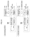
- the switch mechanism is constituted to output the signal of ON when a hairspring provided at the balance with hairspring is brought into contact with terminal members constituting a switch lever.
- the balance rotational angle control mechanism includes a balance magnet provided to the balance with hairspring and a plurality of coils arranged to be capable of exerting a magnetic force to the balance magnet and the coils are constituted to exert the magnetic force to the balance magnet to thereby restrain the rotation of the balance with hairspring when the switch mechanism outputs the signal of ON and not to exert the magnetic force to the balance magnet when the switch mechanism outputs the signal of OFF.
- the mechanical time piece of the invention is provided with a circuit board having patterns for conducting the plurality of coils.
- wiring portions of the plurality of coils are constituted to arrange on a side of the balance magnet of the circuit board.
- the balance rotational angle control mechanism constituted in this way, the rotational angle of the balance with hairspring of the mechanical time piece can effectively be controlled, thereby, accuracy of the mechanical time piece can be promoted.
- the plurality of coils are attached to a coil bridge.
- the circuit board is attached to the coil bridge and the coil bridge is guided by a bearing member provided at the main plate.
- the plurality of coils are attached to coil bridges provided respectively separately, the coil bridges are respectively attached to the circuit board and the coil bridges are guided by the guide holes respectively provided at the main plate.
- the circuit board is provided with patterns for conducting the plurality of coils on one side thereof and is provided with patterns for connecting lead wires for conducting the switch mechanism on other side thereof.
- the plurality of coils are connected in series by the patterns provided to the circuit board.
- the plurality of coils can be arranged efficiently in a small space and the plurality of coils can firmly be conducted.
- the switch mechanism includes a first terminal member and a second terminal member and is further provided with an adjusting apparatus for changing an interval between the first terminal member and the second terminal member.
- the switch mechanism includes a first terminal member and a second terminal member and is further provided with an adjusting apparatus for simultaneously moving the first terminal member and the second terminal member relative to a rotational center of the balance with hairspring.
- a movement (machine body) 700 of the mechanical time piece is provided with a main plate 102 constituting a base plate of the movement.
- a winding stem 110 is rotatably integrated to a winding stem guide hole 102a of the main plate 102.
- a dial 104 (shown by Fig. 2 by imaginary line) is attached to the movement 700.
- the winding stem 110 is provided with a square portion and a guide shaft portion.
- a clutch wheel (not illustrated) is integrated to the square portion of the winding stem 110. That is, the clutch wheel is provided with a rotational axis line the same as a rotational axis line of the winding stem 110. That is, the clutch wheel is provided with a square hole and is provided to rotate based on rotation of the winding stem 110 by fitting the square hole to the square portion of the winding stem 110.
- the clutch wheel is provided with tooth A and tooth B.
- the tooth A is provided at an end portion of the clutch wheel proximate to the center of the movement.
- the tooth B is provided at an end portion of the clutch wheel proximate to an outer side of the movement.
- the movement 700 is provided with a switch apparatus for determining a position of the winding stem 110 in the axial line direction.
- the switch apparatus includes a setting lever 190, a yoke 192, a yoke spring 194 and a setting lever jumper 196.
- the position in the rotational axis line of the winding stem 110 is determined.
- the yoke 192 a position in the rotational axis line direction of the clutch wheel is determined.
- the yoke is positioned to two positions in the rotational direction.
- a winding pinion 112 is provided rotatably at the guide shaft portion of the winding stem 110.
- the winding pinion 112 is constituted to rotate via rotation of the clutch wheel.
- a crown wheel 114 is constituted to rotate by rotation of the winding pinion 112.
- a ratchet wheel 116 is constituted to rotate by rotation of the crown wheel 114.
- the movement 700 is provided with a mainspring 122 contained in a barrel complete 120 as its power source.
- the mainspring 122 is made of an elastic material having spring performance such as iron. By rotating the ratchet wheel 116, the mainspring 122 is constituted to be capable of being wound up.
- a center wheel & pinion 124 is constituted to rotate by rotation of the barrel complete 120.
- a third wheel & pinion 126 is constituted to rotate based on rotation of the center wheel & pinion 124.
- a fourth wheel & pinion 128 is constituted to rotate based on rotation of the third wheel & pinion 126.
- An escape wheel & pinion 130 is constituted to rotate based onrotation of the fourth wheel & pinion 128.
- the barrel complete 120, the center wheel & pinion 124, the third wheel & pinion 126 and the fourth wheel & pinion 128 constitute a front train wheel.
- the movement 700 is provided with an escapement & speed control apparatus for controlling rotation of the front train wheel.
- the escapement & speed control apparatus includes a balance with hairspring 140 repeating right rotation and left rotation at a constant period, the escape wheel & pinion 130 rotating based on rotation of the front train wheel and a pallet fork 142 for controlling rotation of the escape wheel & pinion 130 based on operation of the balance with hairspring 140.
- the balance with hairspring 140 includes a balance stem 140a, a balance wheel 140b and a hairspring 140c.
- the hairspring 140c is made of an elastic material having spring performance such as "elinbar”. That is, the hairspring 140c is made of an electrically conducting material of metal.
- a cannon pinion 150 is simultaneously rotated.
- a minute hand 152 attached to the cannon pinion 150 is constituted to display "minute”.
- the cannon pinion 150 is provided with a slip mechanism having a predetermined slip torque relative to the center wheel & pinion 124.
- a minute wheel (not illustrated) is rotated.
- an hour wheel 154 is rotated.
- An hour hand 156 attached to the hour wheel 154 is constituted to display "hour”.
- the barrel complete 120 is supported rotatably by the main plate 102 and a barrel bridge 160.
- the center wheel & pinion 124, the third wheel & pinion 126, the fourth wheel & pinion 128 and the escape wheel & pinion 130 are supported rotatably by the main plate 102 and a train wheel bridge 162.
- the pallet fork 142 is supported rotatably by the main plate 102 and a pallet bridge 164.
- the balance with hairspring 140 is supported rotatably by the main plate 102 and a balance bridge 166. That is, an upper mortise 140a1 of the balance stem 140a is supported rotatably by a balance upper bearing 166a fixed to the balance bridge 166.
- the balance upper bearing 166a includes a balance upper hole jewel and a balance upper cap jewel.
- the balance upper hole jewel and the balance upper cap jewel are made of an insulating material such as ruby.
- a lower mortise 140a2 of the balance stem 140a is supported rotatably by a balance lower bearing 102b fixed to the main plate 102.
- the balance lower bearing 102b includes a balance lower hole jewel and a balance lower cap jewel.
- the balance lower hole jewel and the balance lower cap jewel are made of an insulating material such as ruby.
- the hairspring 140c is a leaf spring in a helical (spiral) shape having a plural turn number. An inner end portion of the hairspring 140c is fixed to a hairspring holder 140d fixed to the balance stem 140a and an outer end portion of the hairspring 140c is fixed by screws via a hairspring holder 170a attached to a hairspring holder cap 170 rotatably fixed to the balance bridge 166.
- the balance bridge 166 is made of an electrically conductive material of metal such as brass.
- the hairspring holder cap 170 is made of an eclectically conductive material of metal such as iron.
- a switch lever 168 is rotatably attached to the balance bridge 166.
- a first terminal member 168a and a second terminal member 168b are attached to the switch lever 168.
- the switch lever 168 is attached to the balance bridge 166 and is rotatably attached thereto centering on the rotational center of the balance with hairspring 140.
- the switch lever 168 is formed by an insulating material of plastic such as polycarbonate.
- the first terminal member 168a and the second terminal member 168b are fabricated by a conductive material of a metal such as brass.
- a portion of the hairspring 140c proximate to an outer end portion thereof is disposed between the first terminal member 168a and the second terminal member 168b.
- a circuit unit 710 is attached to a face of a front side of the main plate 102.
- the circuit unit 710 includes a circuit board 712 and a coil unit 714.
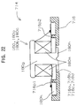
- the coil unit 714 includes a coil bridge 716 and four coils 180, 180a, 180b and 180c. In a state in which the coils 180, 180a, 180b and 180c are arranged to be opposed to a face of the balance wheel 140b on the side of the main plate, the coil unit 714 is attached to the face of the main plate 102 on the front side.
- a number of the coils is, for example, four as shown by Fig. 1 through Fig. 4, the number may be one, may be two, may be three or may be four or more.
- the circuit board 712 is fixed to a face of the coil bridge 716 on the side opposed to the balance wheel 140b by circuit board fixing screws 718.
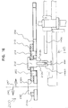
- the circuit unit 710 is attached to the face on the front side of the main plate 102 by circuit unit fixing screws 720. That is, as shown by Fig. 1 through Fig. 4, the coil unit 714 is attached to the face on the front side of the main plate 102 in a state in which the four coils 180, 180a, 180b and 180c are respectively arranged on the side of the balance wheel 140b of the circuit board 612 and in a state in which the circuit board 712 is opposed to the face of the main plate 102 opposed to the main plate 102.
- the coils 180, 180a, 180b and 180c are respectively arranged to the coil bridge 616 such that front end portions 180h on one side are contained in opening portions 716d, 716a, 716b and 716c of the coil bridge 716.
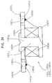
- each of the coils 180, 180a, 180b, 180c is provided with a coil stem 180g and coil boards 180k and 180m.
- the coil stem 180g is constituted by a nonmagnetic material such as plastic or brass.
- the coil stem 180g is provided with a flange portion 180f at one end thereof, a front end portion 180h at other end thereof penetrates the coil board 180k and is fixed to the front side of the coil board 180k by calking or the like.
- the winding portion 180m is provided at an outer periphery of a shaft portion 180j of the coil stem 180g.
- Two terminals 180e of the winding portion 180m are fixed to front side patterns 180s arranged at the coil board 180k on the wiring side. Fixing of the terminal 180e of the wiring portion 180m may be carried out by welding, soldering adhering by using a conductive adhering agent or the like.
- the back side of the circuit board 712 is provided with a first coil conducting pattern 712a provided for conducting in series the front side pattern 180t of the coil board 180k conducted to one terminal of the coil 180 and the front side pattern 180t of the coil board 180k conducted to one terminal of the coil 180a, a second coil conducting pattern 712b provided for conducting in series the front side pattern 180t of the coil board 180k conducted to other terminal of the coil 180a and the front side pattern 180t of the coil board 180k conducted to one terminal of the coil 180b, and a third coil conducting pattern 712c provided for conducting in series the front side pattern 180t of the coil board 180k conducted to other terminal of the coil 180b and the front side pattern 180t of the coil board 180k conducted to one terminal of the coil 180c.
- a first coil conducting pattern 712a provided for conducting in series the front side pattern 180t of the coil board 180k conducted to one terminal of the coil 180 and the front side pattern 180t of the coil board 180k conducted to one terminal of the coil 180a
- the coils 180, 180a, 180b and 180c are conducted in series by three of the coil conducting patterns 712a, 712b and 712c provided at the circuit board 712.
- the back side of the circuit board 712 is provided with a first coil contact pattern 712d for contacting the front side pattern 180t of the coil board 180k conducted to other terminal of the coil 180 and a second coil contact pattern 712e for contacting the front side pattern 180t of the coil board 180k conducted to other terminal of the coil 180c.
- the circuit board 712 is further provided with a first lead connecting pattern 712f and a second lead connecting pattern 712g on its front side.
- the first lead connecting pattern 712f and the first coil contact pattern 712d are conducted by a first through hole 712h.
- the second lead connecting pattern 712g and the second coil contact pattern 712e are conducted by a second through hole 712j.
- Conduction of the lead connecting pattern provided on the front side of the circuit board 712 and the coil contact pattern provided on the back side of the circuit board 712 may be carried out by through hole plating provided at the through hole.
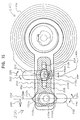
- the operation may be carried out by moving the circuit unit 710 in parallel with the surface of the main plate 102 such that a guiding semicircular arc portion 716w (refer to Fig. 21) of the coil bridge 716 is brought into contact with an outer peripheral portion of the balance lower bearing 102b fixed to the main plate 102.
- the balance lower bearing 102b constitutes a bearing member provided at the main plate 102.
- the circuit unit 710 can be attached to the main plate 102 after attaching the balance with hairspring 140 to the movement.
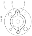
- a coil unit 730 includes a coil bridge 732 and the coil 180.
- An outer peripheral shape of the coil bridge 732 is circular.
- the circuit board 792 is fixed to faces of the respective coil bridges 732 of four of the coil units 730 opposed to the balance wheel 140b by the circuit board fixing screws 718.
- the circuit unit is attached to the face of the main plate 102 on the front side by the circuit unit fixing screws 720. That is, four of the coil units 730 are attached to the face of the main plate 102 on the front side in the state in which four of the coils 180 are respectively arranged on the side of the main plate 102 of the circuit board 792 such that the circuit board 792 is opposed to the face of the balance wheel 140b opposed to the main plate 102.
- Attachment of the circuit unit to the main plate 102 can be carried out by, for example, providing coil guide portions (not illustrated) at the main plate 102 and arranging the circuit unit to the main plate 102 such portions of that the coil unit 730 are contained in the coil guide portions.
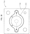
- a coil unit 736 includes a coil bridge 738 and the coil 180.
- the outer peripheral shape of the coil bridge 738 is square.
- the circuit board 792 is fixed to faces of the respective coil bridges 738 of four of the coil units 736 opposed to the balance wheel 140b by the circuit board fixing screws 718.
- the circuit unit is attached to the face of the front side of the main plate 102 by the circuit unit fixing screws 720.
- four of the coil units 736 are attached to the face of the front side of the main plate 102 in a state in which four of the coils 180 are respectively arranged on the side of the balance wheel 140b of the circuit board 792 such that the circuit board 792 is opposed to the face of the balance wheel 140b opposed to the main plate 102.
- Attachment of the circuit unit to the main plate 102 can be realized by, for example, providing coil guide portions (not illustrated) at the main plate 102 and arranging the circuit unit to the main plate 102 such that portions of the coil unit 736 are contained in the coil guide portions.
- a balance magnet 140e is attached to a side face of the balance wheel 140b on the main plate side to be opposed to the face of the main plate 102 on the front side.
- the coil unit 714 is attached to the face on the front side of the main plate 102 in a state in which four of the coils 180, 180a, 180b and 180c are respectively arranged on the side of the balance wheel 140b of the circuit board 612, that is, in a state of being arranged on the side of the balance magnet 140e, that is, in a state in which the circuit board 712 is opposed to the face of the balance wheel 140b opposed to the main plate 102.
- an interval in a circumferential direction of the coil in the case of arranging the plurality of pieces of coils is an interval in the circumferential direction of an S pole and an N pole of the balance magnet 140e arranged to be opposed to the coil multiplied by an integer
- the interval may not be the same for all of the coils in the circumferential direction.
- wirings among the respective coils may be wired in series such that currents generated at the respective coils by electromagnetic induction are not canceled by each other (refer to Fig. 1 through Fig. 4).
- the wirings among the respective coils may be wired in parallel such that currents generated at the respective coils by electromagnetic induction are not canceled by each other (illustration is omitted for such constitution).
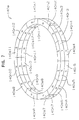
- the balancemagnet 140e is provided with a mode in an annular shape (ring-like shape) and along its circumferential direction, for example, there are alternately provided magnet portions comprising 12 pieces of S poles 140s1 through 140s12 and 12 pieces of N poles 140n1 through 140n12 which are polarized in the up and down direction.
- a number of the magnet portions arranged in the annular shape (ring-like shape) in the balance magnet 140e is 12 in the example shown in Fig. 7, the number may be a plural number of 2 or more. In this case, it is preferable that a length of one chord of the magnet portion is substantially equal to an outer diameter of one coil provided to be opposed to the magnet portion.
- a gap is provided between the balance magnet 140e and the coils 180, 180a, 180b and 180c.
- the gap between the balance magnet 140e and the coils 180, 180a, 180b and 180c, is determined such that magnetic force of the balance magnet 140e can effect influence on the coils 180, 180a, 180b and 180c when the coils 180, 180a, 180b and 180c are conducted.
- the balance magnet 140e is fixed to a face of the balance ring 140b on the side of the main plate by adhering or the like in a state in which one face of the balance magnet 140e is brought into contact with a ring-like rim portion of the balance wheel 140b and other face thereof is opposed to the face of the main plate 102 on the front side.
- a first lead wire 182 is provided to conduct one terminal of the coil 180 and the first terminal member 168a and the second terminal member 168b.
- the first lead wire 182 is connected to a first lead connecting pattern of the circuit board 712 conducted to the one terminal of the coil 180.
- a second lead wire 184 is provided to conduct one terminal of the coil 180c and the hairspring holder 170.
- the second lead wire 184 is connected to a second lead connecting pattern of the circuit board 712 conducted to the one terminal of the coil 180c.
- the thickness of the hairspring 140c is illustrated to exaggerate, the thickness is, for example, 0.021 millimeter.
- the balance magnet 140e for example, an outer diameter thereof is about 9 millimeters, an inner diameter thereof ia bout 7 millimeters, a thickness thereof is about 1 millimeter and a magnetic flux density thereof is about 0.02 tesla.
- a turn number of each of the coils 180, 180a, 180b and 180c is, for example, 8 turns and the coil wire diameter is about 25 micrometers.
- the gap STC between the balance magnet 140e and the coils 180, 180a, 180b and 180c is, for example, about 0.4 millimeter.
- the hairspring 140c is expanded and contracted in the radius direction of the hairspring 140c in accordance with rotational angle of rotating the balance with hairspring 140. For example, in a state shown by Fig. 3, when the balance with hairspring 140 is rotated in the clockwise direction, the hairspring 140c is contracted in a direction toward the center of the balance with hairspring 140, in contrast thereto, when the balance with hairspring 140 is rotated in the counterclockwise direction, the hairspring 140c is expanded in a direction remote from the center of the balance with hairspring 140.
- a constant threshold for example, 180 degree
- an amount of expanding and contracting the hairspring 140c in the radius direction is small and therefore, the hairspring 140c is not brought into contact with the first terminal member 168a and is not brought into contact also with the second terminal member 168b.
- the rotational angle (swing angle) of the balance with hairspring 140 is equal to or larger than the constant threshold, for example, 180 degree, the amount of expanding and contracting the hairspring 140c in the radius direction becomes sufficiently large and accordingly, the hairspring 140c is brought into contact with both of the first terminal member 168a and the second terminal member 168b.
- a portion 140ct of the hairspring 140c proximate to an outer end portion of the hairspring 140c is disposed in a clearance of about 0.04 millimeter between the first terminal member 168a and the second terminal member 168b. Therefore, in a state in which the swing angle of the balance with hairspring 140 falls in a range of exceeding 0 degree and less than 180 degree, the portion 140ct proximate to the outer end portion of the hairspring 140c is not brought into contact with the first terminal member 168a and is not brought into contact also with the second terminal member 168b.
- the outer end portion of the hairspring 140c is not brought into contact with the first terminal member 168a and is not brought into contact also with the second terminal member 168b and accordingly, the coils 180, 180a, 180b and 180c are not conducted and magnetic flux of the balance magnet 140e does not effect influence on the coils 180, 180a, 180b and 180c.
- the swing angle of the balance with hairspring 140 is not attenuated by operation of the balance magnet 140e and the coils 180, 180a, 180b and 180c.
- Fig. 5 and Fig. 6 show a case in which the swing angle of the balance with hairspring 140 is equal to or larger than 180 degree.
- the thickness of the hairspring 140c is illustrated to exaggerate.
- the portion 140ct proximate to the outer end portion of the hairspring 140c is brought into contact with the first terminal member 168a or the second terminal member 168b.
- the coils 180, 180a, 180b and 180c are conducted and a force for restraining rotational motion of the balance with hairspring 140 is exerted to the balance with hairspring 140 by induction current generated by a change in the magnetic flux of the balance magnet 140e. Further, by the operation, braking force for restraining rotation of the balance with hairspring 140 is exerted to the balance with hairspring 140 to thereby reduce the swing angle of the balance with hairspring 140.
- the swing angle of the balance with hairspring 140 is reduced to the range of exceeding 0 degree and less than 180 degree, there is brought about a state in which the portion 140ct proximate to the outer end portion of the hairspring 140c is not brought into contact with the first terminal member 168a and is not brought into contact with the second terminal member 168b. Therefore, as shown by Fig. 3 and Fig. 4, the outer end portion of the hairspring 140c is not brought into contact with the first terminal member 168a and is not brought into contact with the second terminal member 168b and accordingly, the coils 180, 180a, 180b and 180c are not conducted and the magnetic flux of the balance magnet 140e does not effect influence on the coils 180, 180a, 180b and 180c.
- the rotational angle of the balance with hairspring 140 can efficiently be controlled.
- the balance rotational angle control mechanism is provided in the mechanical time piece constituted such that the escapement & speed control apparatus includes the balance with hairspring repeating right rotation and left rotation, the escape wheel & pinion rotated based on rotation of the front train wheel and the pallet fork for controlling rotation of the escape wheel & pinion based on operation of the balance with hairspring and accordingly, accuracy of the mechanical time piece can be promoted without reducing a duration time period of the mechanical time piece.
- Embodiment 2 of a mechanical time piece according to the invention an explanation will be given mainly of a portion of Embodiment 2 of the mechanical time piece of the invention which is different from Embodiment 1 of the mechanical time piece of the invention. Therefore, content described below can be understood by referring to the explanation of Embodiment 1 of the mechanical time piece according to the invention.
- a circuit unit 760 is attached to the face of the front side of the main plate 102.
- the circuit unit 760 includes the circuit board 712 and a coil unit 764.
- the coil unit 764 includes a coil bridge 766 and four of the coils 180, 180a, 180b and 180c.
- the coil unit 764 is attached to the face of the front side of the main plate 102 such that the coils 180, 180a, 180b and 180c are opposed to the face of the balance wheel 140b on the side of the main plate.
- the circuit board 712 is fixed to the face of the coil bridge 766 opposed to the balance wheel 140b by the circuit board fixing screws 718.
- the circuit unit 760 is attached to the face of the front side of the main plate 102 by the circuit unit fixing screws 720. That is, as shown by Fig. 1 through Fig. 4, the coil unit 764 is attached to the face of the main plate 102 on the front side in the state in which four of the coils 180, 180a, 180b and 180c are respectively arranged to the circuit board 712 on the side of the main plate 102 such that the circuit board 712 is opposed to the face of the balance wheel 140b opposed to the main plate 102.
- the circuit board 612 is provided with three of coil conducting patterns (not illustrated) provided to conduct the coil 180, 180a, 180b and 180c in series.
- circuit unit 760 When the circuit unit 760 is attached to the main plate 102, attachment may be carried out such that the circuit unit 760 may be arranged to the surface of the main plate 102 such that a guiding circular arc portion 766w (refer to Fig. 30) of the coil bridge 766 matches the outer peripheral portion of the balance lower bearing 102b fixed to the main plate 102. According to the constitution, the circuit unit 760 is attached to the main plate 102 before attaching the balance with hairspring 140 to the movement.
- the time piece is adjusted in a state in which the instantaneous rate of the time piece is gained.
- the mechanical time piece of the invention in the case in which the balance with hairspring 140 is rotated by a certain angle or more, when the outer end portion of the hairspring 140c is brought into contact with the first terminal member 168a or the second terminal member 168b, the effective length of the hairspring 140c is shortened and accordingly, the instantaneous rate is further gained.
- the rate is about 18 seconds / day (gain of about 18 seconds per day), after elapse of 20 hours from the fully wound state, the instantaneous rate becomes about 13 seconds / day (gain of about 13 seconds / day) and after elapse of 30 hours from the fully wound state, the instantaneous rate becomes about -2 seconds / day (loss of 2 seconds per day).
- the rate is about 25 seconds / day (gain of about 25 seconds per day), after elapse of 20 hours from the fully wound state, the instantaneous rate becomes about 20 seconds / day (gain of about 20 seconds per day) and after elapse of 30 hours from the fully wound state, the instantaneous rate becomes about 5 seconds / day (gain of about 5 seconds per day).
- the instantaneous rate can be maintained at about 5 seconds / day (state of gaining by about 5 seconds per day is maintained) in the state in which the balance rotational angle control mechanism is operated, that is, until elapse of 27 hours from the state in which the mainspring is completely wound up and after elapse of 30 hours from the fully wound state, the instantaneous rate becomes about -2 seconds / day (loss of about 2 seconds per day).
- the mechanical time piece having the balance rotational angle control mechanism of the invention by controlling the swing angle of the balance with hairspring, the change in the instantaneous rate of the time piece is restrained and accordingly, in comparison with the conventional mechanical time piece shown by plots of square and an imaginary line in Fig. 12, an elapse time period from the fully wound state in which the instantaneous rate is about 0 through 5 seconds / day can be prolonged.
- a duration time period in which the instantaneous rate falls within about plus and minus 5 seconds / day is about 32 hours.
- a value of the duration time period is a duration time period in which the instantaneous rate in the conventional mechanical time piece falls within about plus and minus 5 seconds / day or about 22 hours multiplied by 1.45.
- a switch adjusting apparatus 200 includes a switch member 202, a first guide pin 204 and a second guide pin 206 provided to the switch member 202.
- the switch member 202 is formed by a metal such as iron or brass or plastic.
- the first guide pin 204 and the second guide pin 206 are formed by a metal such as iron or brass or plastic.
- the first guide pin 204 and the second guide pin 206 may be formed as members separate from the switch member 202 and fixed to the switch member 202 or the first guide pin 204 and the second guide pin 206 may be formed integrally with the switch member 202.
- the switch member 202 is attached to the balance bridge (not illustrated) to be rotatable centering on the rotational center of the balance with hairspring 140.
- a switch insulating member 210 is arranged to a side of the switch member 202 opposed to a side thereof opposed to the balance with hairspring 140.
- the switch insulating member 210 is formed by an insulating material of plastic or the like and is formed by an elastically deformable material.
- a first long hole 210a is provided to the switch insulating member 210, the first guide pin 204 and the second guide pin 206 are fitted into the first long hole 210a and the switch insulating member 210 is arranged slidably to the switch member 202.
- a direction of sliding the switch insulating member 210 coincides with a straight line passing through a center of the first guide pin 204 or the second guide pin 206 and the center of the balance with hairspring 140.
- a switch interval adjusting lever 212 is provided to the switch insulating member 210 rotatably by a slip mechanism.
- An outer peripheral portion of a cylindrical portion of the switch interval adjusting lever 212 is integrated to a circular portion provided at a portion of the first long hole 210a of the switch insulating member 210.
- the circular portion provided at the portion of the first long hole 210a of the switch insulating member 210 is constituted to be fitted to the cylindrical portion of the switch interval adjusting lever 212 by way of elastic force and accordingly, rotation of the switch interval adjusting lever 212 can be fixed at an arbitrary position.
- a first terminal portion 212a and a second terminal portion 212b are provided on a side of the switch interval adjusting lever 212 opposed to the balance with hairspring 140.
- the first terminal portion 212a and the second terminal portion 212b are provided at positions eccentric to the rotational center of the switch interval adjusting lever 212.
- the first terminal portion 212a and the second terminal portion 212b are formed to constitute line symmetry relative to a straight line including the rotational center of the switch interval adjusting lever 212.
- the portion 140ct proximate to the outer end portion of the hairspring 140c is disposed in a clearance SSW between the first terminal portion 212a and the second terminal portion 212b.
- the clearance SSW is about 0.06 millimeter.
- the first terminal portion 212a and the second terminal portion 212b can be rotated by rotating the switch interval adjusting lever 212 in a direction of an arrow mark 220 (clockwise direction in Fig. 15) or a direction of an arrow mark 222 (counterclockwise direction in Fig. 15). Thereby, the distance SSW between the first terminal portion 212a and the second terminal portion 212b in the direction of the straight line passing through the center of the balance with hairspring 140 can be changed.
- a switch position adjusting lever 232 is provided to the switch member 202 rotatably by a slip mechanism and can be fixed at an arbitrary position.
- An eccentric portion 232a of the switch position adjusting lever 232 is fitted to a second long hole 210b of the switch insulating member 210.
- a direction of a central axis line in the longitudinal direction of the second long hole 210b is orthogonal to the direction of the straight line passing through the center of the first guide pin 204 or the second guide pin 206 and the center of the balance with hairspring 140. That is, the direction of the central axis line in the longitudinal direction of the second long hole 210b is orthogonal to the direction of the central axis line in the longitudinal direction of the first long hole 210a.
- the eccentric portion 232a By rotating the switch position adjusting lever 232 in a direction of an arrow mark 240 (clockwise direction in Fig. 15), the eccentric portion 232a can be rotated. Thereby, the switch insulating member 210 can be moved in a direction toward the center of the balance with hairspring 140 (direction of arrow mark 242 in Fig. 15 and Fig. 16) in the direction of the straight line passing through the center of the balance with hairspring 140. As a result, the first terminal portion 212a is moved to be proximate to the portion 140ct proximate to the outer end portion of the hairspring 140c and the second terminal portion 212b is moved to be remote from the portion 240ct proximate to the outer end portion of the hairspring 140c.
- the eccentric portion 232a By rotating the switch position adjusting lever 232 in a direction of an arrow mark 244 (counterclockwise direction in Fig. 15), the eccentric portion 232a can be rotated. Thereby, the switch insulating member can be moved in a direction remote from the center of the balance with hairspring 140 (direction of arrow mark 246 in Fig. 15 and Fig. 16). As a result, the first terminal portion 212a is moved to be remote from the portion 140ct proximate to the outer end portion of the hairspring 140c and the second terminal portion 212b is moved to be proximate to the portion 140ct proximate to the outer end portion of the hairspring 140c.
- Fig. 17 and Fig. 18 illustrate a state in which the switch position adjusting lever 232 is rotated in the direction of the arrow mark 240 (clockwise direction in Fig. 15) in Fig. 15 and Fig. 16.
- the eccentric portion 232a is rotated, the switch insulating member 210 is moved in the direction toward the center of the balance with hairspring 140, the first terminal portion 212a becomes proximate to the portion 140ct proximate to the outer end portion of the hairspring 140c and the second terminal portion 212b becomes remote from the portion 140ct proximate to the outer end portion of the hairspring 140c.
- the clearance SSW between the first terminal portion 212a and the second terminal portion 212b remains unchanged.
- Fig. 19 and Fig. 20 illustrate a state in which the switch interval adjusting lever 212 is rotated in the direction of the arrow mark 222 (counterclockwise direction in Fig. 15) in Fig. 15 and Fig. 16.
- the switch interval adjusting lever 212 By rotating the switch interval adjusting lever 212, the first terminal portion 212a and the second terminal portion 212b are rotated, the distance between the first terminal portion 212a and the second terminal portion 212b in the direction of the straight line passing through the center of the balance with hairspring 140, is reduced. Therefore, the distance between the first terminal portion 212a and the second terminal portion 212b in the direction of the straight line passing through the center of the balance with hairspring 140 is changed to SSW2 smaller than SSW.
- the first terminal portion 212a may be arranged in place of the first terminal member 168a and the second terminal portion 212b may be arranged in place of the second terminal member 168b.
- the switch adjusting apparatus for the mechanical time piece according to the invention is applicable to a regulating apparatus for an existing mechanical time piece.
- the first terminal portion 212a corresponds to a regulator and the second terminal portion 212b corresponds to a hairspring rod.
- the regulator and the hairspring rod of the mechanical time piece can be adjusted accurately and efficiently.
- the mechanical time piece of the invention is provided with the simple structure and is suitable for realizing a mechanical time piece having very excellent accuracy.
- the mechanical time piece of the invention is provided with the new balance rotational angle control mechanism which has newly been developed and accordingly, a mechanical time piece having high accuracy can be fabricated further efficiently than a conventional time piece.
Abstract
Description
- The present invention relates to a mechanical time piece having a balance rotational angle control mechanism constituted to exert a force for restraining rotation of a balance with hairspring.
- Particularly, the invention relates to a mechanical time piece having a balance rotational angle control mechanism including a balance magnet provided to a balance with hairspring and a coil arranged to be related to the balance magnet.
- According to a conventional mechanical time piece, as shown in Fig. 13 and Fig. 14, a movement (machine body) 1100 of a mechanical time piece is provided with a
main plate 1102 constituting a base plate of the movement. A winding stem 1110 is rotatably integrated to a windingstem guide hole 1102a of themain plate 1102. Adial 1104 (shown in Fig. 14 by an imaginary line) is attached to themovement 1100. - Generally, in both sides of the main plate, a side thereof having the dial is referred to as "back side" of the movement and a side thereof opposed to the side having the dial is referred to as "front side" of the movement. A train wheel integrated to the "front side" of the movement is referred to as "front train wheel" and a train wheel integrated to the "back side" of the movement is referred to as "back train wheel".
- A position in the axis line direction of the winding stem 1110 is determined by a switch apparatus including a
setting lever 1190, ayoke 1192, ayoke spring 1194 and asetting lever jumper 1196. A windingpinion 1112 is provided rotatably at a guide shaft portion of the winding stem 1110. When the winding stem 1110 is rotated in the state in which the winding stem 1110 is disposed at a first winding stem position (0-stage) on a side most proximate to the inner side of the movement along the rotational axis line, thewinding pinion 1112 is rotated via rotation of a clutch wheel. Acrown wheel 1114 is rotated by rotation of the windingpinion 1112. Aratchet wheel 1116 is rotated by rotation of thecrown wheel 1114. By rotating theratchet wheel 1116, amainspring 1122 contained in a barrel complete 1120 is wound up. A center wheel &pinion 1124 is rotated by rotation of the barrel complete 1120. An escape wheel &pinion 1130 is rotated via rotation of a fourth wheel &pinion 1128, a third wheel &pinion 1126 and the center wheel &pinion 1124. The barrel complete 1120, the center wheel &pinion 1124, the third wheel &pinion 1126 and the fourth wheel &pinion 1128 constitute a front train wheel. - An escapement & speed control apparatus for controlling rotation of the front train wheel includes a balance with
hairspring 1140, the escape wheel &pinion 1130 and apallet fork 1142. The balance withhairspring 1140 includes abalance stem 1140a, abalance wheel 1140b and ahairspring 1140c. Based on rotation of the center wheel &pinion 1124, acannon pinion 1150 is simultaneously rotated. Aminute hand 1152 attached to thecannon pinion 1150 displays "minute". Thecannon pinion 1150 is provided with a slip mechanism relative to the center pinion &wheel 1124. Based on rotation of thecannon pinion 1150, via rotation of a minute wheel, anhour wheel 1154 is rotated. Anhour hand 1156 attached to thehour wheel 1154 displays "hour". - The barrel complete 1120 is supported rotatably by the
main plate 1102 and abarrel bridge 1160. The center wheel &pinion 1124, the third wheel &pinion 1126, the fourth wheel &pinion 1128 and the escape wheel &pinion 1130 are supported rotatably by themain plate 1102 and atrain wheel bridge 1162. Thepallet fork 1142 is supported rotatably by themain plate 1102 and apallet bridge 1164. The balance withhairspring 1140 is supported rotatably by themain plate 1102 and abalance bridge 1166. - The
hairspring 1140c is a leaf spring in a helical (spiral) shape having a plural turn number. An inner end portion of thehairspring 1140c is fixed to ahairspring holder 1140d fixed to thebalance stem 1140a and an outer end portion of thehairspring 1140c is fixed via ahairspring stud 1170a attached to astud support 1170 fixed to thebalance bridge 1166 by fastening screws. - A
regulator 1168 is attached rotatably to thebalance bridge 1166. Ahairspring bridge 1168a and ahairspring rod 1168b are attached to theregulator 1168. A portion of thehairspring 1140c proximate to the outer end portion is disposed between thehairspring bridge 1168a and thehairspring rod 1168b. - Generally, according to a conventional representative mechanical timepiece, as shown by Fig. 8, with elapse of a duration time period of rewinding the mainspring from a state in which the mainspring has completely been wound up (fully wound state), mainspring torque is reduced. For example, in the case of Fig. 8, the mainspring torque is about 27 g·cm in the fully wound state, becomes about 23 g·cm after elapse of 20 hours from the fully wound state and becomes about 18 g·cm after elapse of 40 hours from the fully wound state.
- Generally, according to a conventional representative mechanical time piece, as shown by Fig. 9, when the mainspring torque is reduced, the swing angle of the balance with hairspring is also reduced. For example, in the case of Fig. 9, when the mainspring torque is 25-28 g·cm, the swing angle of the balance with hairspring is about 240-270 degree and when the mainspring torque is 20-25 g·cm, the swing angle of the balance with hairspring is about 180-240 degree.
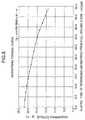
- In reference to Fig. 10, there is shown a transitional change of instantaneous rate with regard to swing angle of a balance with hairspring according to a conventional representative mechanical time piece (numerical value indicating accuracy of time piece). In this case, the "instantaneous rate" is defined as "a value indicating gain or loss of a mechanical time piece after elapse of one day after the mechanical time piece is assumed to be left for one day while maintaining state or environment of swing angle of a balance with hairspring or the like when the rate is measured". In the case of Fig. 10, when a swing angle of a balance with hairspring is equal to or larger than 240 degree or is equal to or smaller than 200 degree, the instantaneous rate is retarded.
- For example, according to a conventional representative time piece, as shown by Fig. 10, when the swing angle of the balance with hairspring falls in a range of about 200 through 240 degree, the instantaneous rate is about 0 through 5 seconds / day (gain of 0 through 5 seconds per day), however, when the swing angle of the balance with hairspring is about 170 degree, the instantaneous rate becomes about -20 seconds / day (loss of about 20 seconds per day).
- In reference to Fig. 12, there is shown a transitional change of elapse time and instantaneous rate when a mainspring is rewound from a fully wound state in a conventional representative mechanical time piece. In this case, in the conventional mechanical time piece, "rate" indicating gain of the timepiece or loss of the time piece per day, is provided by integrating instantaneous rate with regard to elapse time of rewinding the balance with hairspring from a fully wound state, which is indicated in Fig. 12 by an extremely slender line, over 24 hours.
- Generally, according to the conventional mechanical timepiece, with elapse of duration time period of rewinding the mainspring from the fully wound state, the mainspring torque is reduced, the swing angle of the balance with hairspring is also reduced and accordingly, the instantaneous rate is retarded. Therefore, according to the conventional mechanical timepiece, by estimating loss of the time piece after elapse of the duration time period of 24 hours, instantaneous rate when the mainspring is brought into the fully wound state, is previously gained and previously adjusted such that the "rate" indicating gain of the time piece or loss of the time piece per day becomes positive.
- For example, according to the conventional representative time piece, as shown by the extremely slender line in Fig. 12, although in the fully wound state, the instantaneous rate is about 3 seconds / day (gain of about 3 seconds per day), after elapse of 20 hours from the fully wound state, the instantaneous rate becomes about -3 seconds / day (loss of about 3 seconds per day), after elapse of 24 hours from the fully wound state, the instantaneous rate becomes about -8 seconds per day (loss of about 8 seconds per day) and after elapse of 30 hours from the fully wound state, the instantaneous rate becomes about -16 seconds / day (loss of about 16 seconds per day).
- Further, as a conventional apparatus of adjusting a swing angle of a balance with hairspring, there is disclosed in Japanese Utility Model Laid-Open No. 41675/1979, a constitution having a swing angle adjusting plate exerting braking force to a balance with hairspring by generating eddy current at each time of pivotal approach of a magnet of the balance with hairspring.
- Further, as shown by Fig. 36, a conventional
coreless motor 2100 is provided with ashaft 2102, amagnet yoke 2104 fixed to theshaft 2102 and adrive magnet 2106 fixed to themagnet yoke 2104. Astator yoke 2110 is provided rotatably to theshaft 2102 via abearing 2112. A printedcircuit board 2114 is fixed to thestator yoke 2110. Adrive coil 2116 is fixed to the printedcircuit board 2114 to be opposed to thedrive magnet 2106 and spaced apart therefrom. By applying current to thedrive coil 2116, thedrive magnet 2106, themagnet yoke 2104 and theshaft 2102 are constituted to rotate. - It is an object of the invention to provide a mechanical time piece having a balance rotational angle control mechanism capable of controlling a swing angle of a balance with hairspring to fall in a constant range.
- Further, it is an object of the invention to provide a mechanical time piece having excellent accuracy in which a change in a rate is inconsiderable even after elapse of an elapse time period from a fully wound state of a mainspring by providing a novel balance rotational angle control mechanism.
- Further, it is an object of the invention to provide a mechanical time piece constituted such that a balance rotational angle control mechanism includes a balance magnet provided at a balance with hairspring and a coil unit arranged to relate to the balance magnet and constituted such that fabrication and assembly of parts are facilitated.
- According to an aspect of the invention, there is provided a mechanical time piece characterized in that in a mechanical time piece having a main plate constituting a base plate of the mechanical time piece, a mainspring constituting a power source of the mechanical time piece, a front train wheel rotated by a rotational force when the mainspring is rewound and an escapement & speed control apparatus for controlling rotation of the front train wheel in which the escapement & speed control apparatus includes a balance with hairspring alternately repeating right rotation and left rotation, an escape wheel & pinion rotated based on the rotation of the front train wheel and a pallet fork for controlling rotation of the escape wheel & pinion based on operation of the balance with hairspring, the mechanical time piece comprising a switch mechanism constituted to output a signal of ON when a rotational angle of the balance with hairspring becomes equal to or larger than a predetermined threshold and output a signal of OFF when the rotational angle of the balance with hairspring does not exceed the threshold, and a balance rotational angle control mechanism constituted to exert a force for restraining rotation of the balance with hairspring to the balance with hairspring when the switch mechanism outputs the signal of ON.
- According to the mechanical time piece of the aspect of the invention, the switch mechanism is constituted to output the signal of ON when a hairspring provided at the balance with hairspring is brought into contact with terminal members constituting a switch lever.
- Further, according to the mechanical time piece of the aspect of the invention, the balance rotational angle control mechanism includes a balance magnet provided to the balance with hairspring and a plurality of coils arranged to be capable of exerting a magnetic force to the balance magnet and the coils are constituted to exert the magnetic force to the balance magnet to thereby restrain the rotation of the balance with hairspring when the switch mechanism outputs the signal of ON and not to exert the magnetic force to the balance magnet when the switch mechanism outputs the signal of OFF.
- Further, the mechanical time piece of the invention is provided with a circuit board having patterns for conducting the plurality of coils.
- Further, wiring portions of the plurality of coils are constituted to arrange on a side of the balance magnet of the circuit board.
- By using the balance rotational angle control mechanism constituted in this way, the rotational angle of the balance with hairspring of the mechanical time piece can effectively be controlled, thereby, accuracy of the mechanical time piece can be promoted.
- Further, according to the mechanical time piece of the invention, it is preferable that the plurality of coils are attached to a coil bridge.
- Further, according to the mechanical time piece of the invention, it is preferable that the circuit board is attached to the coil bridge and the coil bridge is guided by a bearing member provided at the main plate.
- Further, according to the mechanical time piece of the invention, it is preferable that the plurality of coils are attached to coil bridges provided respectively separately, the coil bridges are respectively attached to the circuit board and the coil bridges are guided by the guide holes respectively provided at the main plate.
- Further, according to the mechanical time piece of the invention, it is preferable that the circuit board is provided with patterns for conducting the plurality of coils on one side thereof and is provided with patterns for connecting lead wires for conducting the switch mechanism on other side thereof.
- Further, according to the mechanical time piece of the invention, it is preferable that the plurality of coils are connected in series by the patterns provided to the circuit board.
- By constituting in this way, the plurality of coils can be arranged efficiently in a small space and the plurality of coils can firmly be conducted.
- Further, according to the mechanical time piece of the invention, it is preferable that the switch mechanism includes a first terminal member and a second terminal member and is further provided with an adjusting apparatus for changing an interval between the first terminal member and the second terminal member.
- Further, according to the mechanical time piece of the invention, it is preferable that the switch mechanism includes a first terminal member and a second terminal member and is further provided with an adjusting apparatus for simultaneously moving the first terminal member and the second terminal member relative to a rotational center of the balance with hairspring.
- By constituting in this way, the positions of the first terminal member and the second terminal member relative to the portion proximate to the outer end portion of the hairspring and the interval between the first terminal member and the second terminal member can effectively be adjusted.
-
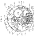
- Fig. 1 is a plane view showing an outline shape of a front side of a movement according to Embodiment 1 of a mechanical time piece of the invention (in Fig. 1, portions of parts are omitted and bridge members are indicated by imaginary lines).
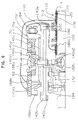
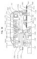
- Fig. 2 is an outline partial sectional view of the movement according to Embodiment 1 of the mechanical time piece of the invention (in Fig. 2, portions of parts are omitted).
- Fig. 3 is a plane view of an enlarged portion showing an outline shape of a portion of a balance with hairspring in a state in which a switch mechanism is made OFF according to Embodiment 1 of the mechanical time piece of the invention (in Fig. 3, a portion of a circuit board is shown to be broken to indicate portions of shapes of coils).
- Fig. 4 is a sectional view of the enlarged portion showing the outline shape of the portion of the balance with hairspring in the state in which the switch mechanism is made OFF according to Embodiment 1 of the mechanical time piece of the invention.
- Fig. 5 is a plane view of the enlarged portion showing the outline shape of the portion of the balance with hairspring in the state in which the switch mechanism is made ON according to Embodiment 1 of the mechanical time piece of the invention (in Fig. 5, a portion of the circuit board is shown to be broken to indicate portions of shapes of coils).
- Fig. 6 is a sectional view of the enlarged portion showing the outline shape of the portion of the balance with hairspring in a state in which the switch mechanism is made ON according to Embodiment 1 of the mechanical time piece of the invention.
- Fig. 7 is a perspective view showing an outline shape of a balance magnet used in a mechanical time piece of the invention.
- Fig. 8 is a graph showing an outline relationship between an elapse time period of rewinding a mainspring from a fully wound state and mainspring torque in a mechanical time piece.
- Fig. 9 is a graph showing an outline relationship between swing angle of a balance with hairspring and mainspring torque in a mechanical time piece .
- Fig. 10 is a graph showing an outline relationshipbetween swing angle of a balance with hairspring and instantaneous rate in a mechanical time piece.
- Fig. 11 is a block diagram showing operation when a circuit is opened and operation when the circuit is closed in a mechanical time piece of the invention.
- Fig. 12 is a graph showing an outline relationship between an elapse time period of rewinding a mainspring from a fully wound state and instantaneous rate according to a mechanical time piece of the invention and a conventional mechanical time piece.
- Fig. 13 is a plane view showing an outline shape of a front side of a movement of a conventional mechanical time piece (in Fig. 13, portions of parts are omitted and bridge members are indicated by imaginary lines).
- Fig. 14 is an outline partial sectional view of the movement of the mechanical time piece (in Fig. 14, portions of parts are omitted).
- Fig. 15 is a plane view showing a switch adjusting apparatus used in a mechanical time piece according to the invention.
- Fig. 16 is a sectional view showing the switch adjusting apparatus used in the mechanical time piece of the invention.
- Fig. 17 is a plane view showing a state of rotating a switch position adjusting lever in the switch adjusting apparatus used in the mechanical time piece of the invention.
- Fig. 18 is a sectional view showing a state of rotating the switch position adjusting lever in the switch adjusting apparatus used in the mechanical time piece of the invention.
- Fig. 19 is a plane view showing a state of rotating a switch interval adjusting lever in the switch adjusting apparatus used in the mechanical time piece of the invention.
- Fig. 20 is a sectional view showing the state of rotating the switch interval adjusting lever in the switch adjusting apparatus used in the mechanical time piece of the invention.
- Fig. 21 is a front plane view showing an outline shape of a coil unit according to Embodiment 1 of a mechanical time piece of the invention.
- Fig. 22 is a sectional view showing the outline shape of the coil unit according to Embodiment 1 of the mechanical time piece of the invention.
- Fig. 23 is a rear plane view showing an outline shape of a coil according to Embodiment 1 of the mechanical time piece of the invention.
- Fig. 24 is a sectional view showing the outline shape of the coil according to Embodiment 1 of the mechanical time piece of the invention.
- Fig. 25 is a front plane view showing an outline shape of a modified mode of a coil unit according to Embodiment 1 of a mechanical time piece of the invention.
- Fig. 26 is a front plane view showing an outline shape of other modified mode of a coil unit according to Embodiment 1 of a mechanical time piece of the invention.
- Fig. 27 is a plane view showing an outline shape of a front side of a movement according to Embodiment 2 of amechanical time piece of the invention (in Fig. 27, portions of parts are omitted and bridge members are indicated by imaginary lines).
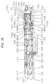
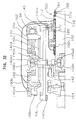
- Fig. 28 is an outline partial sectional view of the movement according to Embodiment 2 of the mechanical time piece of the invention (in Fig. 28, portions of parts are omitted).
- Fig. 29 is a plane view of an enlarged portion showing an outline shape of a portion of a balance with hairspring in a state in which a switch mechanism is made OFF according to Embodiment 2 of the mechanical time piece of the invention (in Fig. 29, a portion of a circuit board is shown to be broken to indicate portions of shapes of coils).
- Fig. 30 is a sectional view of an enlarged portion showing an outline shape of a portion of a balance with hairspring in the state in which the switch mechanism is made OFF according to Embodiment 2 of the mechanical time piece of the invention.
- Fig. 31 is a plane view of the enlarged portion showing the outline shape of the portion of the balance with hairspring in a state in which the switch mechanism is made ON according to Embodiment 2 of the mechanical time piece of the invention (in Fig. 31, a portion of the circuit board is shown to be broken to indicate portions of shapes of coils).
- Fig. 32 is a sectional view of the enlarged portion showing the outline shape of the portion of the balance with hairspring in the state in which the switch mechanism is made ON according to Embodiment 2 of the mechanical time piece of the invention.
- Fig. 33 is a front plane view showing the outline shape of the circuit board used in Embodiment 1 of the mechanical time piece of the invention.
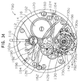
- Fig. 34 is a plane view showing an outline shape of a front side of a movement according to a modified example of Embodiment 1 of the mechanical time piece of the invention (in Fig. 34, portions of parts are omitted and bridge members are indicated by imaginary lines).
- Fig. 35 is an outline partial sectional view of the movement according to the modified example of Embodiment 1 of the mechanical time piece of the invention (in Fig. 35, portions of parts are omitted).
- Fig. 36 is a sectional view showing an outline shape of a conventional motor.
- Fig. 37 is a front plane view showing an outline shape of a circuit board used in a modified example of Embodiment 1 of a mechanical time piece according to the invention.
-
- An explanation will be given of embodiments of a mechanical time piece according to the invention in reference to the drawings as follows.
- In reference to Fig. 1 and Fig. 2, according to an embodiment of a mechanical time piece of the invention, a movement (machine body) 700 of the mechanical time piece is provided with a
main plate 102 constituting a base plate of the movement. A windingstem 110 is rotatably integrated to a windingstem guide hole 102a of themain plate 102. A dial 104 (shown by Fig. 2 by imaginary line) is attached to themovement 700. - The winding
stem 110 is provided with a square portion and a guide shaft portion. A clutch wheel (not illustrated) is integrated to the square portion of the windingstem 110. That is, the clutch wheel is provided with a rotational axis line the same as a rotational axis line of the windingstem 110. That is, the clutch wheel is provided with a square hole and is provided to rotate based on rotation of the windingstem 110 by fitting the square hole to the square portion of the windingstem 110. The clutch wheel is provided with tooth A and tooth B. The tooth A is provided at an end portion of the clutch wheel proximate to the center of the movement. The tooth B is provided at an end portion of the clutch wheel proximate to an outer side of the movement. - The
movement 700 is provided with a switch apparatus for determining a position of the windingstem 110 in the axial line direction. The switch apparatus includes a settinglever 190, ayoke 192, ayoke spring 194 and a settinglever jumper 196. Based on rotation of the clutch wheel, the position in the rotational axis line of the windingstem 110 is determined. Based on rotation of theyoke 192, a position in the rotational axis line direction of the clutch wheel is determined. Based on rotation of the setting lever, the yoke is positioned to two positions in the rotational direction. - A winding
pinion 112 is provided rotatably at the guide shaft portion of the windingstem 110. When the windingstem 110 is rotated in a state in which the windingstem 110 is disposed at a first winding stem position (0-stage) most proximate to the inner side of themovement 300 along the rotational axis line, the windingpinion 112 is constituted to rotate via rotation of the clutch wheel. Acrown wheel 114 is constituted to rotate by rotation of the windingpinion 112. Aratchet wheel 116 is constituted to rotate by rotation of thecrown wheel 114. - The
movement 700 is provided with amainspring 122 contained in a barrel complete 120 as its power source. Themainspring 122 is made of an elastic material having spring performance such as iron. By rotating theratchet wheel 116, themainspring 122 is constituted to be capable of being wound up. - A center wheel &
pinion 124 is constituted to rotate by rotation of the barrel complete 120. A third wheel &pinion 126 is constituted to rotate based on rotation of the center wheel &pinion 124. A fourth wheel &pinion 128 is constituted to rotate based on rotation of the third wheel &pinion 126. An escape wheel &pinion 130 is constituted to rotate based onrotation of the fourth wheel &pinion 128. The barrel complete 120, the center wheel &pinion 124, the third wheel &pinion 126 and the fourth wheel &pinion 128 constitute a front train wheel. - The
movement 700 is provided with an escapement & speed control apparatus for controlling rotation of the front train wheel. The escapement & speed control apparatus includes a balance withhairspring 140 repeating right rotation and left rotation at a constant period, the escape wheel &pinion 130 rotating based on rotation of the front train wheel and apallet fork 142 for controlling rotation of the escape wheel &pinion 130 based on operation of the balance withhairspring 140. - The balance with
hairspring 140 includes abalance stem 140a, abalance wheel 140b and ahairspring 140c. Thehairspring 140c is made of an elastic material having spring performance such as "elinbar". That is, thehairspring 140c is made of an electrically conducting material of metal. - Based on rotation of the center wheel &
pinion 124, acannon pinion 150 is simultaneously rotated. Aminute hand 152 attached to thecannon pinion 150 is constituted to display "minute". Thecannon pinion 150 is provided with a slip mechanism having a predetermined slip torque relative to the center wheel &pinion 124. - Based on rotation of the
cannon pinion 150, a minute wheel (not illustrated) is rotated. Based on rotation of the minute wheel, anhour wheel 154 is rotated. Anhour hand 156 attached to thehour wheel 154 is constituted to display "hour". - The barrel complete 120 is supported rotatably by the
main plate 102 and abarrel bridge 160. The center wheel &pinion 124, the third wheel &pinion 126, the fourth wheel &pinion 128 and the escape wheel &pinion 130 are supported rotatably by themain plate 102 and atrain wheel bridge 162. Thepallet fork 142 is supported rotatably by themain plate 102 and apallet bridge 164. - The balance with
hairspring 140 is supported rotatably by themain plate 102 and abalance bridge 166. That is, an upper mortise 140a1 of thebalance stem 140a is supported rotatably by a balanceupper bearing 166a fixed to thebalance bridge 166. The balanceupper bearing 166a includes a balance upper hole jewel and a balance upper cap jewel. The balance upper hole jewel and the balance upper cap jewel are made of an insulating material such as ruby. - A lower mortise 140a2 of the
balance stem 140a is supported rotatably by a balancelower bearing 102b fixed to themain plate 102. The balancelower bearing 102b includes a balance lower hole jewel and a balance lower cap jewel. The balance lower hole jewel and the balance lower cap jewel are made of an insulating material such as ruby. - The
hairspring 140c is a leaf spring in a helical (spiral) shape having a plural turn number. An inner end portion of thehairspring 140c is fixed to ahairspring holder 140d fixed to thebalance stem 140a and an outer end portion of thehairspring 140c is fixed by screws via ahairspring holder 170a attached to ahairspring holder cap 170 rotatably fixed to thebalance bridge 166. Thebalance bridge 166 is made of an electrically conductive material of metal such as brass. Thehairspring holder cap 170 is made of an eclectically conductive material of metal such as iron. - Next, an explanation will be given of a switch mechanism of the mechanical time piece according to the invention.
- In reference to Fig. 1 and Fig. 2, a
switch lever 168 is rotatably attached to thebalance bridge 166. Afirst terminal member 168a and asecond terminal member 168b are attached to theswitch lever 168. Theswitch lever 168 is attached to thebalance bridge 166 and is rotatably attached thereto centering on the rotational center of the balance withhairspring 140. Theswitch lever 168 is formed by an insulating material of plastic such as polycarbonate. Thefirst terminal member 168a and thesecond terminal member 168b are fabricated by a conductive material of a metal such as brass. A portion of thehairspring 140c proximate to an outer end portion thereof is disposed between thefirst terminal member 168a and thesecond terminal member 168b. - In reference to Fig. 1 through Fig. 4, a
circuit unit 710 is attached to a face of a front side of themain plate 102. Thecircuit unit 710 includes acircuit board 712 and acoil unit 714. Thecoil unit 714 includes acoil bridge 716 and fourcoils coils balance wheel 140b on the side of the main plate, thecoil unit 714 is attached to the face of themain plate 102 on the front side. - Although a number of the coils is, for example, four as shown by Fig. 1 through Fig. 4, the number may be one, may be two, may be three or may be four or more.
- The
circuit board 712 is fixed to a face of thecoil bridge 716 on the side opposed to thebalance wheel 140b by circuit board fixing screws 718. Thecircuit unit 710 is attached to the face on the front side of themain plate 102 by circuit unit fixing screws 720. That is, as shown by Fig. 1 through Fig. 4, thecoil unit 714 is attached to the face on the front side of themain plate 102 in a state in which the fourcoils balance wheel 140b of the circuit board 612 and in a state in which thecircuit board 712 is opposed to the face of themain plate 102 opposed to themain plate 102. - In reference to Fig. 21 and Fig. 22, the
coils front end portions 180h on one side are contained in openingportions coil bridge 716. - Four sets of guide pins 716p1 and 716p2 are provided at the
coil bridge 716. One set of the guide pins 716p1 and 716p2 guide thecoil 180, other set of the guide pins 716p1 and 716p2 guide thecoil 180a, other set of the guide pins 716p1 and 716p2 guide thecoil 180b and other set of the guide pins 716p1 and 716p2 guide thecoil 180c. - In reference to Fig. 23 and Fig. 24, each of the
coils coil stem 180g andcoil boards coil stem 180g is constituted by a nonmagnetic material such as plastic or brass. Thecoil stem 180g is provided with aflange portion 180f at one end thereof, afront end portion 180h at other end thereof penetrates thecoil board 180k and is fixed to the front side of thecoil board 180k by calking or the like. - The winding
portion 180m is provided at an outer periphery of a shaft portion 180j of thecoil stem 180g. Twoterminals 180e of the windingportion 180m are fixed tofront side patterns 180s arranged at thecoil board 180k on the wiring side. Fixing of the terminal 180e of thewiring portion 180m may be carried out by welding, soldering adhering by using a conductive adhering agent or the like. - In reference to Fig. 33, the back side of the
circuit board 712 is provided with a firstcoil conducting pattern 712a provided for conducting in series thefront side pattern 180t of thecoil board 180k conducted to one terminal of thecoil 180 and thefront side pattern 180t of thecoil board 180k conducted to one terminal of thecoil 180a, a second coil conducting pattern 712b provided for conducting in series thefront side pattern 180t of thecoil board 180k conducted to other terminal of thecoil 180a and thefront side pattern 180t of thecoil board 180k conducted to one terminal of thecoil 180b, and a thirdcoil conducting pattern 712c provided for conducting in series thefront side pattern 180t of thecoil board 180k conducted to other terminal of thecoil 180b and thefront side pattern 180t of thecoil board 180k conducted to one terminal of thecoil 180c. - Therefore, according to the constitution shown by Fig. 1 through Fig. 4, the
coils coil conducting patterns circuit board 712. - Further, the back side of the
circuit board 712 is provided with a first coil contact pattern 712d for contacting thefront side pattern 180t of thecoil board 180k conducted to other terminal of thecoil 180 and a secondcoil contact pattern 712e for contacting thefront side pattern 180t of thecoil board 180k conducted to other terminal of thecoil 180c. - The
circuit board 712 is further provided with a firstlead connecting pattern 712f and a second lead connecting pattern 712g on its front side. The firstlead connecting pattern 712f and the first coil contact pattern 712d are conducted by a first throughhole 712h. The second lead connecting pattern 712g and the secondcoil contact pattern 712e are conducted by a second through hole 712j. Conduction of the lead connecting pattern provided on the front side of thecircuit board 712 and the coil contact pattern provided on the back side of thecircuit board 712 may be carried out by through hole plating provided at the through hole. - When the
circuit unit 710 is attached to themain plate 102, the operation may be carried out by moving thecircuit unit 710 in parallel with the surface of themain plate 102 such that a guidingsemicircular arc portion 716w (refer to Fig. 21) of thecoil bridge 716 is brought into contact with an outer peripheral portion of the balancelower bearing 102b fixed to themain plate 102. The balancelower bearing 102b constitutes a bearing member provided at themain plate 102. - According to the constitution, the
circuit unit 710 can be attached to themain plate 102 after attaching the balance withhairspring 140 to the movement. - As a modified example, in reference to Fig. 25, a
coil unit 730 includes acoil bridge 732 and thecoil 180. An outer peripheral shape of thecoil bridge 732 is circular. - In this case, in reference to Fig. 34 and Fig. 35, according to a
movement 790, thecircuit board 792 is fixed to faces of therespective coil bridges 732 of four of thecoil units 730 opposed to thebalance wheel 140b by the circuit board fixing screws 718. The circuit unit is attached to the face of themain plate 102 on the front side by the circuit unit fixing screws 720. That is, four of thecoil units 730 are attached to the face of themain plate 102 on the front side in the state in which four of thecoils 180 are respectively arranged on the side of themain plate 102 of thecircuit board 792 such that thecircuit board 792 is opposed to the face of thebalance wheel 140b opposed to themain plate 102. - Attachment of the circuit unit to the
main plate 102 can be carried out by, for example, providing coil guide portions (not illustrated) at themain plate 102 and arranging the circuit unit to themain plate 102 such portions of that thecoil unit 730 are contained in the coil guide portions. - According to such a constitution, by three of
coil conducting patterns coils 180 are conducted in series. - As other modified example, in reference to Fig. 26, a
coil unit 736 includes acoil bridge 738 and thecoil 180. The outer peripheral shape of thecoil bridge 738 is square. Thecircuit board 792 is fixed to faces of therespective coil bridges 738 of four of thecoil units 736 opposed to thebalance wheel 140b by the circuit board fixing screws 718. The circuit unit is attached to the face of the front side of themain plate 102 by the circuit unit fixing screws 720. That is, four of thecoil units 736 are attached to the face of the front side of themain plate 102 in a state in which four of thecoils 180 are respectively arranged on the side of thebalance wheel 140b of thecircuit board 792 such that thecircuit board 792 is opposed to the face of thebalance wheel 140b opposed to themain plate 102. - Attachment of the circuit unit to the
main plate 102 can be realized by, for example, providing coil guide portions (not illustrated) at themain plate 102 and arranging the circuit unit to themain plate 102 such that portions of thecoil unit 736 are contained in the coil guide portions. - Also according to the constitution, by three of the
coil conducting patterns circuit board 792, four of thecoils 180 are conducted in series. - According to the constitutions of the two modified examples shown here, four of the
same coils 180 are used and accordingly, when one of thecoils 180 is destructed, only the coil can be interchanged. - A
balance magnet 140e is attached to a side face of thebalance wheel 140b on the main plate side to be opposed to the face of themain plate 102 on the front side. - According to the
movement 700 of the embodiment of the mechanical time piece of the invention, as shown by Fig. 1 through Fig. 4, thecoil unit 714 is attached to the face on the front side of themain plate 102 in a state in which four of thecoils balance wheel 140b of the circuit board 612, that is, in a state of being arranged on the side of thebalance magnet 140e, that is, in a state in which thecircuit board 712 is opposed to the face of thebalance wheel 140b opposed to themain plate 102. - Although it is preferable that as shown by Fig. 1, Fig. 3 and Fig. 5, an interval in a circumferential direction of the coil in the case of arranging the plurality of pieces of coils, is an interval in the circumferential direction of an S pole and an N pole of the
balance magnet 140e arranged to be opposed to the coil multiplied by an integer, the interval may not be the same for all of the coils in the circumferential direction. Further, according to such structure of providing the plurality of pieces of coils, wirings among the respective coils may be wired in series such that currents generated at the respective coils by electromagnetic induction are not canceled by each other (refer to Fig. 1 through Fig. 4). - Or, as a modified example, the wirings among the respective coils may be wired in parallel such that currents generated at the respective coils by electromagnetic induction are not canceled by each other (illustration is omitted for such constitution).
- In reference to Fig. 7, the
balancemagnet 140e is provided with a mode in an annular shape (ring-like shape) and along its circumferential direction, for example, there are alternately provided magnet portions comprising 12 pieces of S poles 140s1 through 140s12 and 12 pieces of N poles 140n1 through 140n12 which are polarized in the up and down direction. Although a number of the magnet portions arranged in the annular shape (ring-like shape) in thebalance magnet 140e is 12 in the example shown in Fig. 7, the number may be a plural number of 2 or more. In this case, it is preferable that a length of one chord of the magnet portion is substantially equal to an outer diameter of one coil provided to be opposed to the magnet portion. - A gap is provided between the
balance magnet 140e and thecoils balance magnet 140e and thecoils balance magnet 140e can effect influence on thecoils coils - When the
coils balance magnet 140e does not effect influence on thecoils balance magnet 140e is fixed to a face of thebalance ring 140b on the side of the main plate by adhering or the like in a state in which one face of thebalance magnet 140e is brought into contact with a ring-like rim portion of thebalance wheel 140b and other face thereof is opposed to the face of themain plate 102 on the front side. - A
first lead wire 182 is provided to conduct one terminal of thecoil 180 and thefirst terminal member 168a and thesecond terminal member 168b. Thefirst lead wire 182 is connected to a first lead connecting pattern of thecircuit board 712 conducted to the one terminal of thecoil 180. - A
second lead wire 184 is provided to conduct one terminal of thecoil 180c and thehairspring holder 170. Thesecond lead wire 184 is connected to a second lead connecting pattern of thecircuit board 712 conducted to the one terminal of thecoil 180c. - Further, although in Fig. 4, the thickness of the
hairspring 140c (thickness in radius direction of balance with hairspring) is illustrated to exaggerate, the thickness is, for example, 0.021 millimeter. According to thebalance magnet 140e, for example, an outer diameter thereof is about 9 millimeters, an inner diameter thereof ia bout 7 millimeters, a thickness thereof is about 1 millimeter and a magnetic flux density thereof is about 0.02 tesla. A turn number of each of thecoils balance magnet 140e and thecoils - An explanation will be given of operation of the balance with
hairspring 140 when thecoils - The
hairspring 140c is expanded and contracted in the radius direction of thehairspring 140c in accordance with rotational angle of rotating the balance withhairspring 140. For example, in a state shown by Fig. 3, when the balance withhairspring 140 is rotated in the clockwise direction, thehairspring 140c is contracted in a direction toward the center of the balance withhairspring 140, in contrast thereto, when the balance withhairspring 140 is rotated in the counterclockwise direction, thehairspring 140c is expanded in a direction remote from the center of the balance withhairspring 140. - Therefore, in reference to Fig. 4, when the balance with
hairspring 140 is rotated in the clockwise direction, thehairspring 140c is operated to approach thesecond terminal member 168b. In contrast thereto, when the balance withhairspring 140 is rotated in the counterclockwise direction, thehairspring 140c is operated to approach thefirst terminal member 168a. - When the rotational angle (swing angle) of the balance with
hairspring 140 is less than a constant threshold, for example, 180 degree, an amount of expanding and contracting thehairspring 140c in the radius direction is small and therefore, thehairspring 140c is not brought into contact with thefirst terminal member 168a and is not brought into contact also with thesecond terminal member 168b. - When the rotational angle (swing angle) of the balance with
hairspring 140 is equal to or larger than the constant threshold, for example, 180 degree, the amount of expanding and contracting thehairspring 140c in the radius direction becomes sufficiently large and accordingly, thehairspring 140c is brought into contact with both of thefirst terminal member 168a and thesecond terminal member 168b. - For example, a portion 140ct of the
hairspring 140c proximate to an outer end portion of thehairspring 140c is disposed in a clearance of about 0.04 millimeter between thefirst terminal member 168a and thesecond terminal member 168b. Therefore, in a state in which the swing angle of the balance withhairspring 140 falls in a range of exceeding 0 degree and less than 180 degree, the portion 140ct proximate to the outer end portion of thehairspring 140c is not brought into contact with thefirst terminal member 168a and is not brought into contact also with thesecond terminal member 168b. That is, the outer end portion of thehairspring 140c is not brought into contact with thefirst terminal member 168a and is not brought into contact also with thesecond terminal member 168b and accordingly, thecoils balance magnet 140e does not effect influence on thecoils hairspring 140 is not attenuated by operation of thebalance magnet 140e and thecoils - Next, an explanation will be given of operation of the balance with
hairspring 140 when thecoils hairspring 140 is equal to or larger than 180 degree. - Further, in Fig. 6, the thickness of the
hairspring 140c (thickness in radius direction of balance with hairspring) is illustrated to exaggerate. - When the swing angle of the balance with
hairspring 140 becomes equal to or larger than 180 degree, the portion 140ct proximate to the outer end portion of thehairspring 140c is brought into contact with thefirst terminal member 168a or thesecond terminal member 168b. Under the state, thecoils hairspring 140 is exerted to the balance withhairspring 140 by induction current generated by a change in the magnetic flux of thebalance magnet 140e. Further, by the operation, braking force for restraining rotation of the balance withhairspring 140 is exerted to the balance withhairspring 140 to thereby reduce the swing angle of the balance withhairspring 140. - Further, when the swing angle of the balance with
hairspring 140 is reduced to the range of exceeding 0 degree and less than 180 degree, there is brought about a state in which the portion 140ct proximate to the outer end portion of thehairspring 140c is not brought into contact with thefirst terminal member 168a and is not brought into contact with thesecond terminal member 168b. Therefore, as shown by Fig. 3 and Fig. 4, the outer end portion of thehairspring 140c is not brought into contact with thefirst terminal member 168a and is not brought into contact with thesecond terminal member 168b and accordingly, thecoils balance magnet 140e does not effect influence on thecoils - According to the mechanical time piece of the invention constituted in this way, the rotational angle of the balance with
hairspring 140 can efficiently be controlled. - According to the invention, as explained above, there is constructed the constitution in which the balance rotational angle control mechanism is provided in the mechanical time piece constituted such that the escapement & speed control apparatus includes the balance with hairspring repeating right rotation and left rotation, the escape wheel & pinion rotated based on rotation of the front train wheel and the pallet fork for controlling rotation of the escape wheel & pinion based on operation of the balance with hairspring and accordingly, accuracy of the mechanical time piece can be promoted without reducing a duration time period of the mechanical time piece.
- That is, according to the invention, attention is paid to the correlation between the instantaneous rate and the swing angle by maintaining constant the swing angle, the change in the instantaneous rate is restrained and gain or loss of the time piece per day is adjusted to reduce.
- In contrast thereto, according to the conventional mechanical time piece, by the relationship between the duration time period and the swing angle, the swing angle is changed with elapse of time. Further, by the relationship between the swing angle and the instantaneous rate, the instantaneous rate is changed with elapse of time. Therefore, it has been difficult to prolong the duration time period of the time piece capable of maintaining constant accuracy.
- Next, an explanation will be given of Embodiment 2 of a mechanical time piece according to the invention. In the following explanation, an explanation will be given mainly of a portion of Embodiment 2 of the mechanical time piece of the invention which is different from Embodiment 1 of the mechanical time piece of the invention. Therefore, content described below can be understood by referring to the explanation of Embodiment 1 of the mechanical time piece according to the invention.
- In reference to Fig. 27 through Fig. 30, a
circuit unit 760 is attached to the face of the front side of themain plate 102. Thecircuit unit 760 includes thecircuit board 712 and acoil unit 764. Thecoil unit 764 includes acoil bridge 766 and four of thecoils coil unit 764 is attached to the face of the front side of themain plate 102 such that thecoils balance wheel 140b on the side of the main plate. - The
circuit board 712 is fixed to the face of thecoil bridge 766 opposed to thebalance wheel 140b by the circuit board fixing screws 718. Thecircuit unit 760 is attached to the face of the front side of themain plate 102 by the circuit unit fixing screws 720. That is, as shown by Fig. 1 through Fig. 4, thecoil unit 764 is attached to the face of themain plate 102 on the front side in the state in which four of thecoils circuit board 712 on the side of themain plate 102 such that thecircuit board 712 is opposed to the face of thebalance wheel 140b opposed to themain plate 102. - The circuit board 612 is provided with three of coil conducting patterns (not illustrated) provided to conduct the
coil - When the
circuit unit 760 is attached to themain plate 102, attachment may be carried out such that thecircuit unit 760 may be arranged to the surface of themain plate 102 such that a guiding circular arc portion 766w (refer to Fig. 30) of thecoil bridge 766 matches the outer peripheral portion of the balancelower bearing 102b fixed to themain plate 102. According to the constitution, thecircuit unit 760 is attached to themain plate 102 before attaching the balance withhairspring 140 to the movement. - As shown by Fig. 29 and Fig. 30, operation of the balance with hairspring when the circuit is opened, according to Embodiment 2 of the mechanical time piece of the invention, is similar to the above-described content explained in reference to Fig. 3, Fig. 4 and Fig. 11. Therefore, a detailed explanation thereof will be omitted.
- As shown by Fig. 31 and Fig. 32, operation of the balance with hairspring when the circuit is closed, according to Embodiment 2 of the mechanical time piece of the invention, is similar to the above-described content explained in reference to Fig. 5, Fig. 6 and Fig. 11. Therefore, a detailed explanation thereof will be omitted.
- Next, an explanation will be given of a result of a simulation with regard to the instantaneous rate which is carried out with regard to the mechanical time piece of the invention developed in order to resolve the problem of the conventional mechanical time piece.
- In reference to Fig. 12, according to the mechanical time piece of the invention, first, as shown by plots of x marks and a slender line in Fig. 12, the time piece is adjusted in a state in which the instantaneous rate of the time piece is gained. According to the mechanical time piece of the invention, in the case in which the balance with
hairspring 140 is rotated by a certain angle or more, when the outer end portion of thehairspring 140c is brought into contact with thefirst terminal member 168a or thesecond terminal member 168b, the effective length of thehairspring 140c is shortened and accordingly, the instantaneous rate is further gained. - That is, according to the mechanical time piece of the invention, in a state in which the outer end portion of the
hairspring 140c is not brought into contact with thefirst terminal member 168a and is not brought into contact with thesecond terminal member 168b, as shown by the plots of x marks and the slender line in Fig. 12, in a state in which the main spring is completely wound up, the rate is about 18 seconds / day (gain of about 18 seconds per day), after elapse of 20 hours from the fully wound state, the instantaneous rate becomes about 13 seconds / day (gain of about 13 seconds / day) and after elapse of 30 hours from the fully wound state, the instantaneous rate becomes about -2 seconds / day (loss of 2 seconds per day). - Further, according to the mechanical time piece of the invention, when the balance rotational angle control mechanism is assumed not to operate, as shown by plots of triangle and a bold line in Fig. 12, in a state in which the outer end portion of the
hairspring 140c is brought into contact with thefirst terminal member 168a or thesecond terminal member 168b, in the state in which the mainspring is completely wound up, the rate is about 25 seconds / day (gain of about 25 seconds per day), after elapse of 20 hours from the fully wound state, the instantaneous rate becomes about 20 seconds / day (gain of about 20 seconds per day) and after elapse of 30 hours from the fully wound state, the instantaneous rate becomes about 5 seconds / day (gain of about 5 seconds per day). - In contrast thereto, according to the mechanical time piece of the invention, when the balance rotational angle control mechanism is operated, as shown by plots of black circle and an extremely bold line in Fig. 12, the instantaneous rate can be maintained at about 5 seconds / day (state of gaining by about 5 seconds per day is maintained) in the state in which the balance rotational angle control mechanism is operated, that is, until elapse of 27 hours from the state in which the mainspring is completely wound up and after elapse of 30 hours from the fully wound state, the instantaneous rate becomes about -2 seconds / day (loss of about 2 seconds per day).
- According to the mechanical time piece having the balance rotational angle control mechanism of the invention, by controlling the swing angle of the balance with hairspring, the change in the instantaneous rate of the time piece is restrained and accordingly, in comparison with the conventional mechanical time piece shown by plots of square and an imaginary line in Fig. 12, an elapse time period from the fully wound state in which the instantaneous rate is about 0 through 5 seconds / day can be prolonged.
- That is, according to the mechanical time piece of the invention, a duration time period in which the instantaneous rate falls within about plus and minus 5 seconds / day is about 32 hours. A value of the duration time period is a duration time period in which the instantaneous rate in the conventional mechanical time piece falls within about plus and minus 5 seconds / day or about 22 hours multiplied by 1.45.
- Therefore, according to the mechanical time piece of the invention, in comparison with the conventional mechanical time piece, there is achieved the result of the simulation in which accuracy is every excellent.
- Next, an explanation will be given of a switch adjusting apparatus used for adjusting positions of the first terminal member and the second terminal member relative to the
portion 140 proximate to the outer end portion of the hairspring and an interval between the first terminal member and the second terminal member. - In reference to Fig. 15 and Fig. 16, a
switch adjusting apparatus 200 includes aswitch member 202, afirst guide pin 204 and asecond guide pin 206 provided to theswitch member 202. Theswitch member 202 is formed by a metal such as iron or brass or plastic. Thefirst guide pin 204 and thesecond guide pin 206 are formed by a metal such as iron or brass or plastic. Thefirst guide pin 204 and thesecond guide pin 206 may be formed as members separate from theswitch member 202 and fixed to theswitch member 202 or thefirst guide pin 204 and thesecond guide pin 206 may be formed integrally with theswitch member 202. Theswitch member 202 is attached to the balance bridge (not illustrated) to be rotatable centering on the rotational center of the balance withhairspring 140. - A
switch insulating member 210 is arranged to a side of theswitch member 202 opposed to a side thereof opposed to the balance withhairspring 140. Theswitch insulating member 210 is formed by an insulating material of plastic or the like and is formed by an elastically deformable material. A firstlong hole 210a is provided to theswitch insulating member 210, thefirst guide pin 204 and thesecond guide pin 206 are fitted into the firstlong hole 210a and theswitch insulating member 210 is arranged slidably to theswitch member 202. A direction of sliding theswitch insulating member 210 coincides with a straight line passing through a center of thefirst guide pin 204 or thesecond guide pin 206 and the center of the balance withhairspring 140. - A switch
interval adjusting lever 212 is provided to theswitch insulating member 210 rotatably by a slip mechanism. An outer peripheral portion of a cylindrical portion of the switchinterval adjusting lever 212 is integrated to a circular portion provided at a portion of the firstlong hole 210a of theswitch insulating member 210. The circular portion provided at the portion of the firstlong hole 210a of theswitch insulating member 210, is constituted to be fitted to the cylindrical portion of the switchinterval adjusting lever 212 by way of elastic force and accordingly, rotation of the switchinterval adjusting lever 212 can be fixed at an arbitrary position. - A
first terminal portion 212a and a second terminal portion 212b are provided on a side of the switchinterval adjusting lever 212 opposed to the balance withhairspring 140. Thefirst terminal portion 212a and the second terminal portion 212b are provided at positions eccentric to the rotational center of the switchinterval adjusting lever 212. Thefirst terminal portion 212a and the second terminal portion 212b are formed to constitute line symmetry relative to a straight line including the rotational center of the switchinterval adjusting lever 212. - The portion 140ct proximate to the outer end portion of the
hairspring 140c is disposed in a clearance SSW between thefirst terminal portion 212a and the second terminal portion 212b. For example, the clearance SSW is about 0.06 millimeter. - The
first terminal portion 212a and the second terminal portion 212b can be rotated by rotating the switchinterval adjusting lever 212 in a direction of an arrow mark 220 (clockwise direction in Fig. 15) or a direction of an arrow mark 222 (counterclockwise direction in Fig. 15). Thereby, the distance SSW between thefirst terminal portion 212a and the second terminal portion 212b in the direction of the straight line passing through the center of the balance withhairspring 140 can be changed. - Further, a switch
position adjusting lever 232 is provided to theswitch member 202 rotatably by a slip mechanism and can be fixed at an arbitrary position. Aneccentric portion 232a of the switchposition adjusting lever 232 is fitted to a secondlong hole 210b of theswitch insulating member 210. A direction of a central axis line in the longitudinal direction of the secondlong hole 210b is orthogonal to the direction of the straight line passing through the center of thefirst guide pin 204 or thesecond guide pin 206 and the center of the balance withhairspring 140. That is, the direction of the central axis line in the longitudinal direction of the secondlong hole 210b is orthogonal to the direction of the central axis line in the longitudinal direction of the firstlong hole 210a. Elasticdeformable portions switch insulating member 210 the widths of which are formed to be elastically deformable, are provided at both end portions in the longitudinal direction of the secondlong hole 210b. Arigid portion 210e of theswitch insulating member 210, the width of which is formed not to be elastically deformable, is provided on an outer side (side remote from the outer end portion of themainspring 140c) of the secondlong hole 210b. Therefore, the width of therigid portion 210e is formed to be larger than the widths of the elasticallydeformable portions rigid portion 210e is arranged to be brought into contact with theeccentric portion 232a of the switchposition adjusting lever 232. - By rotating the switch
position adjusting lever 232 in a direction of an arrow mark 240 (clockwise direction in Fig. 15), theeccentric portion 232a can be rotated. Thereby, theswitch insulating member 210 can be moved in a direction toward the center of the balance with hairspring 140 (direction ofarrow mark 242 in Fig. 15 and Fig. 16) in the direction of the straight line passing through the center of the balance withhairspring 140. As a result, thefirst terminal portion 212a is moved to be proximate to the portion 140ct proximate to the outer end portion of thehairspring 140c and the second terminal portion 212b is moved to be remote from the portion 240ct proximate to the outer end portion of thehairspring 140c. - By rotating the switch
position adjusting lever 232 in a direction of an arrow mark 244 (counterclockwise direction in Fig. 15), theeccentric portion 232a can be rotated. Thereby, the switch insulating member can be moved in a direction remote from the center of the balance with hairspring 140 (direction ofarrow mark 246 in Fig. 15 and Fig. 16). As a result, thefirst terminal portion 212a is moved to be remote from the portion 140ct proximate to the outer end portion of thehairspring 140c and the second terminal portion 212b is moved to be proximate to the portion 140ct proximate to the outer end portion of thehairspring 140c. - Fig. 17 and Fig. 18 illustrate a state in which the switch
position adjusting lever 232 is rotated in the direction of the arrow mark 240 (clockwise direction in Fig. 15) in Fig. 15 and Fig. 16. By rotating the switchposition adjusting lever 232, theeccentric portion 232a is rotated, theswitch insulating member 210 is moved in the direction toward the center of the balance withhairspring 140, thefirst terminal portion 212a becomes proximate to the portion 140ct proximate to the outer end portion of thehairspring 140c and the second terminal portion 212b becomes remote from the portion 140ct proximate to the outer end portion of thehairspring 140c. In such operation of rotating the switchposition adjusting lever 232, the clearance SSW between thefirst terminal portion 212a and the second terminal portion 212b remains unchanged. - Fig. 19 and Fig. 20 illustrate a state in which the switch
interval adjusting lever 212 is rotated in the direction of the arrow mark 222 (counterclockwise direction in Fig. 15) in Fig. 15 and Fig. 16. By rotating the switchinterval adjusting lever 212, thefirst terminal portion 212a and the second terminal portion 212b are rotated, the distance between thefirst terminal portion 212a and the second terminal portion 212b in the direction of the straight line passing through the center of the balance withhairspring 140, is reduced. Therefore, the distance between thefirst terminal portion 212a and the second terminal portion 212b in the direction of the straight line passing through the center of the balance withhairspring 140 is changed to SSW2 smaller than SSW. - As has been explained, according to the mechanical time piece of the invention, by using the
switch adjusting apparatus 200, the positions of thefirst terminal portion 212a and the second terminal portion 212b relative to the portion 140ct proximate to the outer end portion of the hairspring can be adjusted and by adjusting the interval between thefirst terminal portion 212a and the second terminal portion 212b, the distance between the portion 140ct proximate to the outer end portion of the hairspring and thefirst terminal portion 212a and the distance between the portion 140ct proximate to the outer end portion of the hairspring and the second terminal portion 212b can be adjusted. - By applying the above-described two adjustingmechanisms to the switch adjusting apparatus, swing angles for making the switch ON/OFF can easily be adjusted.
- Therefore, when the
switch adjusting apparatus 200 is used in the mechanical time piece of the invention shown in Fig. 1 and Fig. 2, thefirst terminal portion 212a may be arranged in place of thefirst terminal member 168a and the second terminal portion 212b may be arranged in place of thesecond terminal member 168b. - The switch adjusting apparatus for the mechanical time piece according to the invention is applicable to a regulating apparatus for an existing mechanical time piece. In such a case, the
first terminal portion 212a corresponds to a regulator and the second terminal portion 212b corresponds to a hairspring rod. - By such a constitution, the regulator and the hairspring rod of the mechanical time piece can be adjusted accurately and efficiently.
- The mechanical time piece of the invention is provided with the simple structure and is suitable for realizing a mechanical time piece having very excellent accuracy.
- Further, the mechanical time piece of the invention is provided with the new balance rotational angle control mechanism which has newly been developed and accordingly, a mechanical time piece having high accuracy can be fabricated further efficiently than a conventional time piece.
Claims (8)
- A mechanical time piece characterized in that in a mechanical time piece having a main plate constituting a base plate of the mechanical time piece, a mainspring constituting a power source of the mechanical time piece, a front train wheel rotated by a rotational force when the mainspring is rewound and an escapement & speed control apparatus for controlling rotation of the front train wheel in which the escapement & speed control apparatus includes a balance with hairspring alternately repeating right rotation and left rotation, an escape wheel & pinion rotated based on the rotation of the front train wheel and a pallet fork for controlling rotation of the escape wheel & pinion based on operation of the balance with hairspring, said mechanical time piece comprising:a switch mechanism (168, 168a, 168b) constituted to output a signal of ON when a rotational angle of the balance with hairspring (140) becomes equal to or larger than a predetermined threshold and output a signal of OFF when the rotational angle of the balance with hairspring (140) does not exceed the threshold; anda balance rotational angle control mechanism (140e, 180) constituted to exert a force for restraining rotation of the balance with hairspring (140) to the balance with hairspring (140) when the switch mechanism (168, 168a, 168b) outputs the signal of ON;wherein the switch mechanism (168, 168a, 168b) is constituted to output the signal of ON when a hairspring (140c) provided at the balance with hairspring (140) is brought into contact with terminal members (168a, 168b) constituting a switch lever;wherein the balance rotational angle control mechanism (140e, 180) includes a balance magnet (140e) provided to the balance with hairspring (140) and a plurality of coils (180, 180a, 180b, 180c) arranged to be capable of exerting a magnetic force to the balance magnet (140e);wherein the coils (180, 180a, 180b, 180c) are constituted to exert the magnetic force to the balance magnet (140e) to thereby restrain the rotation of the balance with hairspring (140) when the switch mechanism (168, 168a, 168b) outputs the signal of ON and not to exert the magnetic force to the balance magnet (140e) when the switch mechanism (168, 168a, 168b) outputs the signal of OFF, further comprising:a circuit board (712) having patterns for conducting the plurality of coils (180, 180a, 180b, 180c);wherein wiring portions of the plurality of coils (180, 180a, 180b, 180c) are constituted to arrange on a side of the balance magnet (140e) of the circuit board (712).
- The mechanical time piece according to Claim 1, characterized in that the plurality of coils (180, 180a, 180b, 180c) are attached to a coil bridge (716).
- The mechanical time piece according to Claim 1 or Claim 2, characterized in that the circuit board (712) is attached to the coil bridge (716) and the coil bridge (712) is guided by a bearing member (102b) provided to the main plate (102).
- The mechanical time piece according to Claim 1 or Claim 2, characterized in that the plurality of coils (180, 180a, 180b, 180c) are attached to coil bridges (732, 736) provided respectively separately, the coil bridges (732, 736) are respectively attached to the circuit board (712).
- The mechanical time piece according to any one of Claim 2 through Claim 4, characterized in that the circuit board (712) is provided with patterns for conducting the plurality of coils (180, 180a, 180b, 180c) on one side thereof and is provided with patterns for connecting lead wires for conducting the switch mechanism (168, 168a, 168b) on other side thereof.
- The mechanical time piece according to any one of Claim 2 through Claim 5, characterized in that the plurality of coils (180, 180a, 180b, 180c) are connected in series by the patterns provided to the circuit board (712).
- The mechanical time piece according to any one of Claim 1 through Claim 6, characterized in that the switch mechanism (168, 168a, 168b) includes a first terminal member (168a) and a second terminal member (168b) and is further provided with an adjusting apparatus (200) for changing an interval between the first terminal member (168a) and the second terminal member (168b).
- The mechanical time piece according to any one of Claim 1 through Claim 6, characterized in that the switch mechanism (168, 168a, 168b) includes a first terminal member (168a) and a second terminal member (168b) and is further provided with an adjusting apparatus (200) for simultaneously moving the first terminal member (168a) and the second terminal member (168b) relative to a rotational center of the balance with hairspring (140).
Applications Claiming Priority (1)
| Application Number | Priority Date | Filing Date | Title |
|---|---|---|---|
| PCT/JP1999/006293 WO2001035172A1 (en) | 1999-11-11 | 1999-11-11 | Mechanical timepiece with timed annular balance rotating angle control mechanism including coils |
Publications (1)
| Publication Number | Publication Date |
|---|---|
| EP1143308A1 true EP1143308A1 (en) | 2001-10-10 |
Family
ID=14237266
Family Applications (1)
| Application Number | Title | Priority Date | Filing Date |
|---|---|---|---|
| EP99974172A Withdrawn EP1143308A1 (en) | 1999-11-11 | 1999-11-11 | Mechanical timepiece with timed annular balance rotating angle control mechanism including coils |
Country Status (3)
| Country | Link |
|---|---|
| EP (1) | EP1143308A1 (en) |
| CN (1) | CN1333886A (en) |
| WO (1) | WO2001035172A1 (en) |
Families Citing this family (3)
| Publication number | Priority date | Publication date | Assignee | Title |
|---|---|---|---|---|
| EP1359476A1 (en) * | 2002-05-02 | 2003-11-05 | Zenith International SA | Mechanical timepiece with tourbillon |
| CH697273B1 (en) * | 2006-07-26 | 2008-07-31 | Detra Sa | An electromechanical escapement and timepiece provided with such a device |
| CN112363374B (en) * | 2020-11-02 | 2022-05-17 | 东莞市迪尚智能生活科技有限公司 | Watch winding system and method based on Internet of things |
Family Cites Families (4)
| Publication number | Priority date | Publication date | Assignee | Title |
|---|---|---|---|---|
| US3698179A (en) * | 1970-07-20 | 1972-10-17 | Timex Corp | Contact assembly for electric watches |
| BE790818A (en) * | 1971-11-01 | 1973-02-15 | Timex Corp | AMPLITUDE CONTROL MEANS FOR BALANCER OSCILLATORS |
| JPS5441675U (en) * | 1977-08-29 | 1979-03-20 | ||
| JPH04167579A (en) | 1990-10-31 | 1992-06-15 | Nec Corp | Electrostrictive effect element and manufacture thereof |
-
1999
- 1999-11-11 EP EP99974172A patent/EP1143308A1/en not_active Withdrawn
- 1999-11-11 CN CN99815555.1A patent/CN1333886A/en active Pending
- 1999-11-11 WO PCT/JP1999/006293 patent/WO2001035172A1/en not_active Application Discontinuation
Non-Patent Citations (1)
| Title |
|---|
| See references of WO0135172A1 * |
Also Published As
| Publication number | Publication date |
|---|---|
| CN1333886A (en) | 2002-01-30 |
| WO2001035172A1 (en) | 2001-05-17 |
Similar Documents
| Publication | Publication Date | Title |
|---|---|---|
| US6554468B1 (en) | Mechanical timepiece with timed annular balance rotating angle control mechanism | |
| JP4630621B2 (en) | Watch with mechanical movement connected to an electronic regulator | |
| CN109298619B (en) | Hollow watch including a movement independent of the middle part of the case | |
| JP2005106830A (en) | Watch equipped with mechanical movement coupled with electronic regulator | |
| EP1241538A1 (en) | Mechanical timepiece with timed annular balance power generating control mechanism | |
| JP3562817B2 (en) | Mechanical watch with attitude detection device | |
| EP1143308A1 (en) | Mechanical timepiece with timed annular balance rotating angle control mechanism including coils | |
| JP2011117768A (en) | Chronograph timepiece | |
| EP1093036B1 (en) | Mechanical timepiece with timed annular balance rotating angle control mechanism | |
| EP1359475A1 (en) | Mechanical timepiece with posture detector and the posture detector | |
| EP1172713A1 (en) | Mechanical timepiece with optical detecting part and braking part | |
| EP1109081A1 (en) | Mechanical timepiece with timed annular balance rotating angle control mechanism | |
| EP1217329A1 (en) | Attitude detecting device | |
| JP2004184412A (en) | Timepiece having residual electric power indicator | |
| EP1178372A1 (en) | Posture detection part and mechanical timepiece having electrostatic capacity type detection part | |
| EP0238934B1 (en) | Stepping motor and frame plate assembly for a wristwatch movement | |
| EP1048989B1 (en) | Electronically controlled mechanical timepiece and method of manufacturing the same | |
| JP3631767B6 (en) | Mechanical watch with balance rotation angle control mechanism | |
| EP1174776A1 (en) | Mechanical timepiece with posture detecting part and optical timed annular balance rotation detecting part | |
| JP3718634B2 (en) | Attitude detection device | |
| EP1178371A1 (en) | Mechanical timepiece with electrostatic capacity type detecting part and braking part | |
| EP1048990B1 (en) | Electronically controlled mechanical timepiece | |
| US3844104A (en) | Electromechanical transducer for watches | |
| JPH01158382A (en) | Electronic time-piece |
Legal Events
| Date | Code | Title | Description |
|---|---|---|---|
| PUAI | Public reference made under article 153(3) epc to a published international application that has entered the european phase |
Free format text: ORIGINAL CODE: 0009012 |
|
| AK | Designated contracting states |
Kind code of ref document: A1 Designated state(s): AT BE CH CY DE DK ES FI FR GB GR IE IT LI LU MC NL PT SE |
|
| AX | Request for extension of the european patent |
Free format text: AL;LT;LV;MK;RO;SI |
|
| 17P | Request for examination filed |
Effective date: 20011112 |
|
| RBV | Designated contracting states (corrected) |
Designated state(s): CH LI |
|
| REG | Reference to a national code |
Ref country code: DE Ref legal event code: 8566 |
|
| STAA | Information on the status of an ep patent application or granted ep patent |
Free format text: STATUS: THE APPLICATION IS DEEMED TO BE WITHDRAWN |
|
| 18D | Application deemed to be withdrawn |
Effective date: 20040601 |