EP1174743A2 - N X M optical switch - Google Patents
N X M optical switch Download PDFInfo
- Publication number
- EP1174743A2 EP1174743A2 EP01121213A EP01121213A EP1174743A2 EP 1174743 A2 EP1174743 A2 EP 1174743A2 EP 01121213 A EP01121213 A EP 01121213A EP 01121213 A EP01121213 A EP 01121213A EP 1174743 A2 EP1174743 A2 EP 1174743A2
- Authority
- EP
- European Patent Office
- Prior art keywords
- wedge
- light
- grin lens
- port
- lens
- Prior art date
- Legal status (The legal status is an assumption and is not a legal conclusion. Google has not performed a legal analysis and makes no representation as to the accuracy of the status listed.)
- Withdrawn
Links
- 230000003287 optical effect Effects 0.000 title claims abstract description 179
- 238000000034 method Methods 0.000 claims description 3
- 230000008878 coupling Effects 0.000 abstract description 15
- 238000010168 coupling process Methods 0.000 abstract description 15
- 238000005859 coupling reaction Methods 0.000 abstract description 15
- 238000010586 diagram Methods 0.000 description 19
- 238000004519 manufacturing process Methods 0.000 description 7
- 230000001902 propagating effect Effects 0.000 description 7
- 239000000835 fiber Substances 0.000 description 5
- 239000013307 optical fiber Substances 0.000 description 4
- 239000002131 composite material Substances 0.000 description 3
- 230000000694 effects Effects 0.000 description 3
- 230000005540 biological transmission Effects 0.000 description 2
- 230000035945 sensitivity Effects 0.000 description 2
- BJQHLKABXJIVAM-UHFFFAOYSA-N bis(2-ethylhexyl) phthalate Chemical compound CCCCC(CC)COC(=O)C1=CC=CC=C1C(=O)OCC(CC)CCCC BJQHLKABXJIVAM-UHFFFAOYSA-N 0.000 description 1
- 239000011248 coating agent Substances 0.000 description 1
- 238000000576 coating method Methods 0.000 description 1
- 230000002939 deleterious effect Effects 0.000 description 1
- 238000006073 displacement reaction Methods 0.000 description 1
- 238000001914 filtration Methods 0.000 description 1
- 238000003780 insertion Methods 0.000 description 1
- 230000037431 insertion Effects 0.000 description 1
- 238000002955 isolation Methods 0.000 description 1
- 239000000463 material Substances 0.000 description 1
- 239000000758 substrate Substances 0.000 description 1
Images




Classifications
-
- G—PHYSICS
- G02—OPTICS
- G02B—OPTICAL ELEMENTS, SYSTEMS OR APPARATUS
- G02B6/00—Light guides; Structural details of arrangements comprising light guides and other optical elements, e.g. couplings
- G02B6/24—Coupling light guides
- G02B6/26—Optical coupling means
- G02B6/35—Optical coupling means having switching means
- G02B6/351—Optical coupling means having switching means involving stationary waveguides with moving interposed optical elements
- G02B6/3524—Optical coupling means having switching means involving stationary waveguides with moving interposed optical elements the optical element being refractive
-
- G—PHYSICS
- G02—OPTICS
- G02B—OPTICAL ELEMENTS, SYSTEMS OR APPARATUS
- G02B26/00—Optical devices or arrangements for the control of light using movable or deformable optical elements
- G02B26/08—Optical devices or arrangements for the control of light using movable or deformable optical elements for controlling the direction of light
- G02B26/0875—Optical devices or arrangements for the control of light using movable or deformable optical elements for controlling the direction of light by means of one or more refracting elements
- G02B26/0883—Optical devices or arrangements for the control of light using movable or deformable optical elements for controlling the direction of light by means of one or more refracting elements the refracting element being a prism
- G02B26/0891—Optical devices or arrangements for the control of light using movable or deformable optical elements for controlling the direction of light by means of one or more refracting elements the refracting element being a prism forming an optical wedge
-
- G—PHYSICS
- G02—OPTICS
- G02B—OPTICAL ELEMENTS, SYSTEMS OR APPARATUS
- G02B6/00—Light guides; Structural details of arrangements comprising light guides and other optical elements, e.g. couplings
- G02B6/24—Coupling light guides
- G02B6/26—Optical coupling means
- G02B6/35—Optical coupling means having switching means
- G02B6/351—Optical coupling means having switching means involving stationary waveguides with moving interposed optical elements
- G02B6/3524—Optical coupling means having switching means involving stationary waveguides with moving interposed optical elements the optical element being refractive
- G02B6/3528—Optical coupling means having switching means involving stationary waveguides with moving interposed optical elements the optical element being refractive the optical element being a prism
-
- H—ELECTRICITY
- H04—ELECTRIC COMMUNICATION TECHNIQUE
- H04J—MULTIPLEX COMMUNICATION
- H04J14/00—Optical multiplex systems
- H04J14/02—Wavelength-division multiplex systems
- H04J14/0201—Add-and-drop multiplexing
- H04J14/0202—Arrangements therefor
- H04J14/021—Reconfigurable arrangements, e.g. reconfigurable optical add/drop multiplexers [ROADM] or tunable optical add/drop multiplexers [TOADM]
- H04J14/0212—Reconfigurable arrangements, e.g. reconfigurable optical add/drop multiplexers [ROADM] or tunable optical add/drop multiplexers [TOADM] using optical switches or wavelength selective switches [WSS]
-
- H—ELECTRICITY
- H04—ELECTRIC COMMUNICATION TECHNIQUE
- H04Q—SELECTING
- H04Q11/00—Selecting arrangements for multiplex systems
- H04Q11/0001—Selecting arrangements for multiplex systems using optical switching
- H04Q11/0005—Switch and router aspects
-
- G—PHYSICS
- G02—OPTICS
- G02B—OPTICAL ELEMENTS, SYSTEMS OR APPARATUS
- G02B6/00—Light guides; Structural details of arrangements comprising light guides and other optical elements, e.g. couplings
- G02B6/24—Coupling light guides
- G02B6/26—Optical coupling means
- G02B6/35—Optical coupling means having switching means
- G02B6/351—Optical coupling means having switching means involving stationary waveguides with moving interposed optical elements
- G02B6/3512—Optical coupling means having switching means involving stationary waveguides with moving interposed optical elements the optical element being reflective, e.g. mirror
-
- G—PHYSICS
- G02—OPTICS
- G02B—OPTICAL ELEMENTS, SYSTEMS OR APPARATUS
- G02B6/00—Light guides; Structural details of arrangements comprising light guides and other optical elements, e.g. couplings
- G02B6/24—Coupling light guides
- G02B6/26—Optical coupling means
- G02B6/35—Optical coupling means having switching means
- G02B6/354—Switching arrangements, i.e. number of input/output ports and interconnection types
- G02B6/3544—2D constellations, i.e. with switching elements and switched beams located in a plane
- G02B6/3546—NxM switch, i.e. a regular array of switches elements of matrix type constellation
-
- G—PHYSICS
- G02—OPTICS
- G02B—OPTICAL ELEMENTS, SYSTEMS OR APPARATUS
- G02B6/00—Light guides; Structural details of arrangements comprising light guides and other optical elements, e.g. couplings
- G02B6/24—Coupling light guides
- G02B6/26—Optical coupling means
- G02B6/35—Optical coupling means having switching means
- G02B6/354—Switching arrangements, i.e. number of input/output ports and interconnection types
- G02B6/356—Switching arrangements, i.e. number of input/output ports and interconnection types in an optical cross-connect device, e.g. routing and switching aspects of interconnecting different paths propagating different wavelengths to (re)configure the various input and output links
-
- H—ELECTRICITY
- H04—ELECTRIC COMMUNICATION TECHNIQUE
- H04J—MULTIPLEX COMMUNICATION
- H04J14/00—Optical multiplex systems
- H04J14/02—Wavelength-division multiplex systems
- H04J14/0201—Add-and-drop multiplexing
- H04J14/0202—Arrangements therefor
- H04J14/0206—Express channels arrangements
-
- H—ELECTRICITY
- H04—ELECTRIC COMMUNICATION TECHNIQUE
- H04Q—SELECTING
- H04Q11/00—Selecting arrangements for multiplex systems
- H04Q11/0001—Selecting arrangements for multiplex systems using optical switching
- H04Q11/0005—Switch and router aspects
- H04Q2011/0007—Construction
- H04Q2011/0016—Construction using wavelength multiplexing or demultiplexing
-
- H—ELECTRICITY
- H04—ELECTRIC COMMUNICATION TECHNIQUE
- H04Q—SELECTING
- H04Q11/00—Selecting arrangements for multiplex systems
- H04Q11/0001—Selecting arrangements for multiplex systems using optical switching
- H04Q11/0005—Switch and router aspects
- H04Q2011/0007—Construction
- H04Q2011/0024—Construction using space switching
Definitions
- This invention relates generally to optical switches and more particularly, to an optical switch having a movable wedge or a plurality of movable wedges which allow the switch to have a plurality of states.
- optical switch that is rugged, substantially insensitive to temperature changes within an operating range of temperature, and relatively inexpensive to manufacture.
- Such switches are required to be capable of switching a beam of light propagating in a waveguide, for example an optical fibre from a first similar waveguide, to a second.
- the core diameter of a single mode optical fibre is approximately 10 ⁇ m.
- Each GRIN lens has two ports offset from the optical axis (OA) of the lens.
- switches have been developed by JDS Fitel Inc. that are easier to manufacture being much less sensitive to angular and/or lateral deviation of the movable optical element disposed between the GRIN lenses.
- a transmissive optical element in which zero or an even number of internal reflections in each plane, and/or any number of refractions, are imposed on the incident light between the lenses rather than a reflective element imposing one reflection, to route, shift, or direct a beam from one port to an alternate port when the element is disposed between lenses.
- the switch is much less sensitive to angular deviation and misalignment of the element than a switch using a reflective element such as a mirror.
- a transmissive element such as a prism
- the switch is much less sensitive to angular deviation and misalignment of the element than a switch using a reflective element such as a mirror.
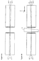
- Figs. 2a and 2b illustrate a 4-port 2 x 2 optical switch having 4 GRIN lenses wherein the ports are disposed along the optical axes of the lenses.
- light launched into port 1 of GRIN lens 20a traverses the gap between the lenses and couples into lens 20b and exits port 2.
- light launched into port 3 couples to port 4 in this bar-state.
- a movable prism is positioned into the gap between the four GRIN lenses.
- the prism can be rotatable such that in a bar-state it is rotated so that its sides are parallel to the end faces of the GRIN lenses 20a, 20b, 20c, and 20d wherein no deflection occurs, and in a cross-state the prism 25 is rotated into the position shown in Fig. 2b.
- Manufacturing a four port 2 x 2 switch such as the one shown in Fig. 2b is difficult because in a cross-state not only does port 1 have to align with port 3, but simultaneously, port 2 must align with port 4.
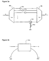
- Configurable add drop optical circuits require one or more switches or elements providing the functionality of switching in the event that a signal is to be added or dropped to another optical signal path.
- the configurable add drop circuit shown in Fig. 3a allows an n-channel multiplexed signal to pass from point A to point B while providing the capability to drop one or more of the n-channels and simultaneously add a new same channel. For example a composite signal having wavelengths ⁇ a to ⁇ n is launched into the multiplexor 30a and is passed on to point B via the multiplexor 30b.
- switches 31a and 31c will selected to be in a cross-switching state such that ports 1 and 2 are coupled, and ports 3 and 4 are coupled. Otherwise, if neither adding nor dropping is desired, the switch will be in a bar-state.
- the switch is the type shown in Figs. 1a and 1b, or 2a and 2b, is that add and drop ports become coupled to one another. This can have deleterious effects and is not always a desired goal.
- the switch in accordance with this invention provides an elegant solution to this problem. Furthermore, the switch in accordance with this invention obviates the difficult requirement of ensuring that two pairs of ports are simultaneously coupled in a bar-state and in a cross-state.
- an optical switch comprising:
- an optical switch comprising:
- an add-drop optical circuit comprising: a first multiplex/demultiplexor; a second multiplex/demultiplexor; waveguides disposed between the first and second multiplex/demultiplexors; and a plurality of 1 1 ⁇ 2 x 2 optical switches coupled to at least some of the waveguides for adding and dropping optical signals, the optical switches substantially preventing optical signals from propagating from an add port to a drop port.
- an add-drop optical circuit comprising: a demultiplexor/multiplexor for demultiplexing a composite optical signal having a plurality of channels; multiplexor/demultiplexor for multiplexing a plurality of signals into a composite optical signal, the demultiplexor/multiplexor and multiplexor/demultiplexor having waveguides disposed therebetween for carrying optical signals from the multiplexor/demultiplexor to the demultiplexor/multiplexor, at least a pair of waveguides being coupled to a 1 1 ⁇ 2 x 2 optical switch, for adding and dropping optical signals to and from the optical waveguides respectively, the optical switch having only one connection between only two ports in a first state and having two simultaneous connections, connecting a first port with a drop port, and a third port with an add port in a second state, the optical switch disallowing and preventing optical signals from propagating from an add port through the switch to a drop port in the first state.
- a 4-port optical switch comprising:
- an optical switch which comprises: at least one input port on one side for launching a beam of light along an optical path; at least two output ports on an opposite side for receiving the beam of light, a first of the at least two output ports optically coupled to the at least one input port; and a light transmissive wedge having at least two non-parallel surfaces, the light transmissive wedge movable into and out of the optical path, the wedge movable at least between first, second, and third positions corresponding to first, second, and third connect states, respectively.
- At least one of the at least two non-parallel surfaces corresponds to an input face of the light transmissive wedge and another of the at least two non-parallel surfaces corresponds to an output face of the light transmissive wedge.
- the input and output faces of the light transmissive wedge can be light transmissive surfaces for refracting the beam of light passing therethrough.
- One of the input and output surfaces may comprise at least a reflective area for reflecting back the beam of light incident thereon so that the beam of light launched into the at least one input port is optically coupled to an output port located on the same side of the light transmissive wedge as the input port substantially opposite the at least two output ports.
- An actuator is provided for moving the light transmissive wedge into and out of the optical path.
- the actuator is a three or more position actuator for positioning the light transmissive wedge at least in the first, second and third positions, wherein in the first position the actuator moves the wedge out of the optical path for providing a single connection between the at least one input port and a first output port; in the second position the actuator moves the wedge into the optical path for single connection between the at least one input port and a second output port; and in the third position the actuator moves the wedge such that the reflective area is positioned in the optical path for single connection between the at least one input port and a third output port.
- the optical switch may comprise at least a first GRIN lens optically coupled to the at least one input port for substantially collimating the beam of light onto the light transmissive wedge and for focusing the beam of light reflected from the reflective surface to the third output port in the third connect state.
- At least a second GRIN lens can be provided which is substantially coaxial to the first GRIN lens and optically coupled to at least two output ports for focusing the collimated beam of light from the first GRIN lens to the first output port in the first connect state and from the light transmissive wedge to the second output port in the second connect state.
- At least another light transmissive wedge having at least two non-parallel surfaces can be provided, the at least other wedge movable into and out of the optical path for allowing at least a fourth, a fifth, a sixth and a seventh connect states.
- the optical switch can comprise a first GRIN lens and a second GRIN lens, the first GRIN lens optically coupled to the at least one input port and the second GRIN lens optically coupled to the at least two output ports, the lenses being arranged such that their inner end faces are facing one another to allow the beam of light launched into the at least one input port to couple to one of the at least two output ports on the outer end face of the second lens.
- the optical switch can comprise a multifaceted wedge movable into and out of the optical path; a multifaceted wedge corresponding to an arrangement of a plurality of light transmissive wedges in close contact, each of the light transmissive wedge having at least two non-parallel surfaces wherein a surface of the at least two non-parallel surfaces of each light transmissive wedge corresponds to an input surface and another surface of the at least two non-parallel surfaces of each light transmissive wedge corresponds to an output surface.
- An area of at least one facet of the multifaceted wedge can have a reflective area for reflecting back the beam of light incident thereon.
- a method for switching a beam of light from one of a plurality of output ports to another comprising the step of: receiving at an input port a beam of light parallel to the optical axis of a first GRIN lens for collimating the beam of light; transmitting the beam of light along an optical path to a second GRIN lens optically coupled to the plurality of output ports, the second GRIN lens for focusing the beam of light; and inserting a wedge into the optical path for modifying the optical path so that the beam of light switches from one of the plurality of output ports and so that the beam of light exits the second GRIN lens at a predetermined output port of the plurality of output ports substantially parallel to the optical axis of the GRIN lens.
- the step of inserting the wedge comprises ensuring that the optical signal enters the second GRIN lens at an angle substantially concentric with the optical axis.
- ensuring that the optical signal enters the second GRIN lens at an angle substantially concentric with the optical axis comprises focusing the beam of light at a specific output port of the plurality of output ports coupled to the second GRIN lens.
- Inserting the wedge into the optical path of the beam of light comprises using an actuator for moving the wedge.
- the method for switching a beam of light from one of a plurality of output ports to another can also comprise the step of inserting at least another different movable wedge into the optical path.
- inserting another different movable wedge into the optical path comprises moving the other movable wedge.
- Preferred embodiments of this invention are based on the use of a light transmissive wedge that is defined as an optical medium, whereby the two refracting planes are mutually arranged such that there is a finite angle or angles therebetween, such angle(s) being defined in either or both of the planes comprising the optical axis.
- the wedge angle(s) and centre thickness are optimised, given judicious choice of material to form the wedge, to give the desired radial offset at the focal plane of the lens, together with optimal fibre coupling efficiency.
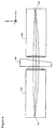
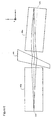
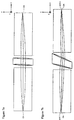
- Fig.5a a beam is launched into a first quarter pitch lens 40a so that its collimated or near-collimated output traverses the optical element in the form of a wedge 44, as defined above.
- the lenses 40a share the same optical axis and, in order to avoid unwanted etalon effects, have their inner end faces polished such that, viewed in the xz plane, they appear as lines subtending equal and opposite angles to the x-axis.
- Fig. 5a a beam is launched into a first quarter pitch lens 40a so that its collimated or near-collimated output traverses the optical element in the form of a wedge 44, as defined above.
- the lenses 40a share the same optical axis and, in order to avoid unwanted etalon effects, have their inner end faces polished such that, viewed in the xz plane, they appear as lines subtending equal and opposite angles to the x-axis.
- the lenses are disposed such that lines extending along their optical axes intersect and do not share a common optical axis. It can be seen that the effect on the collimated or near-collimated beam traversing the wedge 44 is that it is refracted by the first and second faces of the wedge; these refractions, in combination with the propagation through the wedge, have the net effect of angularly deviating the beam, on leaving the wedge, with respect to the incident angle of the beam. In this embodiment the light exiting the wedge is angularly deviated through a positive angle in the yz plane and consequently enters the lens 40a at an angle. Similar to Fig.
- the wedge 44 in Fig. 5b is oriented such that only two ports, port 1 and port 4 are optically coupled, light not coupling between the other two ports; rather light input from port 3 forms an output image radially displaced at least 100 microns away from the nearest active port, therefore there is no optical crosstalk. It can be seen that light from port 3 is directed to a location 57 offset from port 4 to which it couples light when the wedge is removed.
- the embodiments shown in Figs 7(a) and 7(b) demonstrate that the wedge may have angles defined in both planes containing the optical axis.
- Fig. 5a The operation of the optical switch shown in Fig. 5a and 5b is as follows.
- Fig. 5a the switch is shown in a first state with no wedge present between the ports, having ports 1 and 2 optically coupled, and having ports 3 and 4 simultaneously optically coupled.
- ports 1 and 4 are optically coupled and ports 3 and 2 are not coupled to each other or to the other ports.
- known mechanical means can be provided to move the wedge 44 out of the path of the beams.
- a solenoid driving a cam coupled to the wedge (not shown) is provided.
- an embodiment which is not preferred, but will function as a 1 1 ⁇ 2 x 2 optical switch is one wherein the moveable element disposed in between the two GRIN lenses providing only one coupling between two ports, the other two ports being optically uncoupled, is a single sided reflector between the two lenses.
- FIG. 8 An optical arrangement is shown in Fig. 8, wherein two quarter pitch GRIN lenses 310a and 310b are disposed so that their collimating ends are adjacent one another in a back-to-back relationship.
- a very thin optical element in the form of a filter 312 is sandwiched therebetween.
- the filter 312 can be coated directly on one of the inwardly facing end faces of the lenses, or alternatively may be coated on a substrate that is antireflection coated and sandwiched between the two GRIN lenses 310a and 310b. It should be noted, that the optical axes of the input/output fibres 311a and 311b are parallel with the optical axes of the two GRIN lenses.
- the beam traversing the lenses 310a and 310b about the filter element 312 is at a location substantially coincident with the optical axes of the GRIN lenses, the light input orthogonal to the end face of the lens 310a at port P 1 , propagates through the filter 312 and through the second lens 310b and exits at port P 2 as a focused beam that is parallel to the input beam and the optical axes of the lenses 310a and 310b.
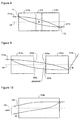
- Fig. 9 illustrates an offset that occurs when a gap is present between a pair of coaxial GRIN lenses 312a and 312b.
- the beam exiting the lens 312a intersects the end face equidistant from the optical axis indicated by lines 320a and 320b, which define the outer most limits of the beam as it traverses the lens 312a end face.
- the beam traverses the inwardly facing end face of the lens 312b having its outermost limits defined by the locations 322a and 322b which are not equidistant from the optical axis OA of the second lens 312b.
- This beam shift downward results in the output beam being directed upward along the optical axis of the optical fibre 314b. Accordingly, substantial coupling losses may occur between an input port on a first GRIN lens and an output port on a second GRIN lens, when the input and output ports are disposed adjacent the optical axes of the two GRIN lenses, and wherein a gap separating the GRIN lenses causes a beam propagating from the input port through the first GRIN lens to be shifted as it traverses the element towards the output port and enters the second lens at an offset to the optical axis of the lens.
- the fibre 314b is provided at an angle ⁇ > 0 degrees with respect to the optical axis of the lens.
- the beam 330 it is also possible, as shown in Fig. 10, to launch the beam 330 at a judiciously selected angle ⁇ s at the left input end face of the GRIN lens 316b in such a way that the beam is selectively directed towards a desired output port location at the right output end face of the GRIN lens 316b.
- the beam thus propagates through the lens 316b and exits the output end of the lens parallel to the OA of the lens.
- Fig. 11a shows the first connect state of the optical switch in accordance with another embodiment of the invention wherein a wedge 50 is moved out of the beam path.
- a pair of quarter pitch GRIN lenses 18a and 18b, having end faces parallel to each other, disposed back to back sharing the same optical axis are slightly spaced apart.
- Two optical waveguides 41 and 42 are shown coaxial with and coupled to the lenses along the optical axis of the lenses 18a and 18b shown by a dotted line.
- a beam profile is also shown within the lenses 18a and 18b as if light was launched from the waveguide 41 to the respective lens 18a and exited the lens 18b at output 1 to the waveguide 42.
- Fig. 11b illustrates the second connect state wherein an actuator, for example in a form of a three-position actuator 100, moves the wedge 50 into the path of the beam between the coaxial GRIN lenses 18a and 18b.
- the wedge 50 is defined herein as an optical medium having two non-parallel surfaces, which for exemplary purposes are shown as input end 51 and output end 52. The angle between the two non-parallel surfaces and the centre thickness of the wedge are judiciously chosen to give optimal fibre coupling.
- Either the upper half or the lower half area of the wedge facing the collimating GRIN lens is coated with a reflective coating.
- either the other of the upper half or the lower half area of the wedge facing the collimating GRIN lens is light transmissive.
- the input end face 51 of the wedge 50 is facing the end face 19a of the GRIN lens 18a; the angle existing between the surface 51 and the optical axis of the GRIN lens 18a is substantially about 90°.
- the output end face 52 of the wedge 50 is facing the input end 19b of the second GRIN lens 18b; the second non parallel surface 52 is not normal to the optical axis of the GRIN lens 18b.
- a beam of light parallel to the optical axis is launched into the input end of the GRIN lens 18a; at the end face 19a, the collimated beam concentric with the optical axis of the lens exits the lens and is incident on the transmissive surface 50a of the wedge 50.
- the beam is slightly refracted into the wedge and exits the wedge 50 at the face 52 oriented towards the input end 19b of the lens 18b.
- the angle of the surface 52 with respect to the end face 19b of the lens 18b is chosen to ensure that the light enters the input end 19b of the lens 18b and is directed towards an output port 2.
- the substantial coincidence of the beam of light with the optical axis allows the focussed beam to exit the lens 18b substantially parallel to the optical axis at the output port 2.
- the third connect state is illustrated in Fig. 11c.
- the three-position actuator 100 moves the wedge 50 into the path of the beam between the coaxial GRIN lenses 18a and 18b.
- the wedge 50 is the same wedge described previously.
- the wedge is placed such that the reflective surface 50b of the surface 51 faces the end face 19a of the lens 18a.
- a beam of light parallel to the optical axis is launched into the input end of the GRIN lens 18a; at the end face 19a of the GRIN lens 18a, the collimated beam substantially concentric with the optical axis of the lens exits the lens and is incident on the reflective surface 50b of the wedge 50. The beam is then reflected back into the same GRIN lens 18a.
- the angle between the surface 51 and the optical axis is substantially about 90°. The exact angle is chosen to ensure that the collimated light is redirected toward output port 3.
- the reflective beam of light is substantially concentric with the optical axis of the lens, thus the focussed beam exits the lens 18a substantially parallel to the optical axis at the output port 3 located on the same end face that the input beam was launched through.
- additional wedges are provided between two substantially coaxial GRIN lenses to increase the number of ports.
- additional wedges are provided between two substantially coaxial GRIN lenses to increase the number of ports.
- movable wedges 60 similar but not identical to the wedge 50 previously described, between the output surface 52 of the wedge 50 and the input end 19b of the lens 18b, the number of output ports is changed.
- Fig. 12 details the different connect states achieved when a second movable asymmetric light transmissive wedge 60 having two non-parallel to each other surfaces forming an input end 61 and an output end 62 is inserted into the switch.
- the second wedge 60 is moved in or out of the path of the beam of light with a second three- position actuator 200.
- Fig. 12 details the different connect states achieved when a second movable asymmetric light transmissive wedge 60 having two non-parallel to each other surfaces forming an input end 61 and an output end 62 is inserted into the switch.
- the second wedge 60 is moved in or out of the path of
- the three-position actuator 200 moves the wedge 60 into the path of the beam between the wedge 50 and the input face of the GRIN lens 18b.
- the input end face 61 of the wedge 60 is oriented towards the output end face 52 of the wedge 50; the output end face 62 of the wedge 60 is oriented towards the input end 19b of the second GRIN lens 18b.
- a beam of light parallel to the optical axis is launched into the input end of the GRIN lens 18a; at the end face 19a of the GRIN lens 18a, the collimated beam concentric with the optical axis of the lens exits the lens and is incident on the transmissive surface 50a of the wedge 50.
- the beam is then slightly refracted into the wedge and exits the wedge at the surface 52 oriented towards the transmissive surface 60a of the wedge 60; the beam is slightly bent into the wedge 60 and exits the wedge at the surface 62 oriented towards the input end 19b of the lens 18b.
- the angle of the surfaces 61 with respect to the optical axis on one hand and the angle of the surface 62 with respect to the optical axis on another hand are chosen to ensure that the light enters the input end 19b of the lens 18b and is directed towards an output port 4.
- the coincidence of the beam of light with the optical axis makes the focussed beam exiting the lens 18b substantially parallel to the optical axis at the output port 4.
- Fig. 12b shows a fifth connect state wherein the three-position actuator 100 moves the wedge 50 out of the path of the beam whereas the three-position actuator 200 places the wedge 60 into the path of the beam of light between the coaxial GRIN lenses 18a and 18b. Because of the absence of the wedge 50, the beam of light exiting the output end 19a of the lens 18a propagates through the air before contacting the input transmissive surface 60a of the wedge 60. The beam of light is refracted into the wedge 60 and exits the wedge at the output surface 62 oriented towards the input end 19b of the lens 18b. The angle of the surfaces 61 and 62 with respect to the optical axis are chosen to ensure that the light enters the input end 19b of the lens 18b and is directed towards an output port 5. The coincidence of the beam of light with the optical axis makes the focussed beam exiting the lens 18b substantially parallel to the optical axis at the output port 5.
- a sixth connect state is illustrated in Fig. 12c.
- the three-position actuators 100 and 200 move the wedges 50 and 60 into the path of the beam between the coaxial GRIN lenses 18a and 18b.
- the wedge 50 is moved in a position allowing the beam of light to pass therethrough in its second connect state, i.e., the transmissive surface 50a is oriented towards the end face 19a of the lens 18a.
- the wedge 60 is placed such that the reflective surface 60b of the surface 61 is oriented towards the end 52 of the wedge 50.
- a beam of light parallel to the optical axis is launched into the input end of the GRIN lens 18a; at the end face 19a of the GRIN lens 18a, the collimated beam concentric with the optical axis of the lens exits the lens and enters the input transmissive face 50a of the wedge 50; the beam is bent into the wedge and exits the wedge 50 at the output end 52 to propagate to the wedge 60 where it contacts the reflective surface 60b of the wedge 60. The beam is reflected back into the wedge 50. The beam is refracted again while propagating through the wedge 50 and is directed towards a selected output port 6, located on the same end face that the input beam was launched through. Moreover, the reflective beam of light is substantially concentric with the optical axis of the lens, thus the focussed beam exits the lens 18a substantially parallel to the optical axis at the output port 6.
- Fig. 12d shows a seventh connect state where the wedge 50 is moved out of the path of the beam by the three-position actuator 100 whereas the three-position actuator 200 positions the reflective surface 60b of the wedge 60 in the path of the beam of light.
- a beam of light parallel to the optical axis is launched at the input end of the GRIN lens 18a; at the end face 19a of the GRIN lens 18a, the collimated beam concentric with the optical axis of the lens exits the lens to contact the reflective surface 60b of the wedge 60. The beam is then reflected back into the same GRIN lens 18a.
- the angle of the surface 61 is chosen to ensure that the collimated light is redirected toward output port 7.
- the reflective beam of light is substantially concentric with the optical axis of the lens, thus the focussed beam exits the lens 18a substantially parallel to the optical axis at the output port 7 located on the same end face that the input beam was launched through.
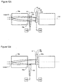
- Fig. 13a, 13b and 13c illustrate an embodiment wherein additional input ports are provided.
- each beam of light is represented by a single ray of light.
- One optical path is shown with a solid line and the other is shown with a dashed line.
- Only one wedge 50 is shown in this embodiment.
- Fig. 13a shows a connect state when the wedge 50 is moved out of the optical paths.
- a beam of light parallel to, and off the optical axis of the GRIN lenses 18a and 18b, launched into input port 110 is directed towards an output port A.
- Another beam of light parallel to, and off the optical axis of the GRIN lenses 18a and 18b launched into input port 120 is directed towards an output port B.
- the substantial coincidence of the beams of light with the optical axis allows the focussed beams to exit the lens 18b substantially parallel to the optical axis at the output ports A and B.
- Fig. 13b shows the paths of the beams of light when the wedge 50 is moved between the two GRIN lenses 18a and 18b such that the transmissive surface 50a of the wedge 50 is placed between the end face 19a of the GRIN lens 18a and the input face 19b of the GRIN lens 18b.
- the beam of light launched from the input port 110 is optically coupled to an output port C
- the beam of light launched from the input port 120 is optically coupled to an output port D.
- the characteristics and displacement (or position) of the wedge allow the beams of light to exit the GRIN lens 18b substantially parallel to the optical axis of the lenses.
- the actuator 100 has moved the wedge 50 between the two GRIN lenses 18a and 18b so that the reflective surface 50b of the wedge 50 is oriented towards the end face 19a of the GRIN lens 18a.
- the beam of light launched from input port 110 is reflected back to the GRIN lens 18a and directed towards an output port E located on the same side of the input port 110.
- the beam of light launched from input port 120 is reflected back to the GRIN lens 18a and focussed at an output port F located on the same side of the input port 120.
- the characteristics of the wedge allow the beams of light to exit the GRIN lens 18b substantially parallel to the optical axis of the lens.
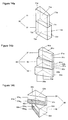
- Fig. 14a shows a multifaceted wedge 70 having at least two different wedged-shaped parts, 71 and 72.
- the two wedged-shaped parts are disposed so that the wedge 71 is on the top of and in contact with the wedge 72.
- the wedge 71 has at least two non-parallel surfaces 71a and 71b and at least two other surfaces 71c and 71d, wherein the width of surface 71c is smaller than the width of the surface 71d.
- the wedge 72 has at least two non-parallel surfaces 72a and 72b, and at least two other surfaces 72c and 72d, wherein the width of surface 72c is smaller than the width of the surface 72d.
- the wedges are positioned so that the smallest surface 72c of the wedge 72 is below the largest surface 71d of the wedge 71, and the largest surface 72d of the wedge 72 is below the smallest surface 71c of the wedge 71.
- the angle between the two non-parallel surfaces and the centre thickness of the wedges 71 and 72 are selected so that, when the multifaceted wedge 70 is inserted between a pair of GIRN lenses, a beam of light incident thereon is refracted and directed towards a predetermined output port as described above.
- Fig. 14b shows another example of a multifaceted wedge 80.
- the wedge 80 has at least three wedged-shaped parts, 81, 82 and 83.
- the general arrangement is that the wedge 81 is on top of and in contact with the wedge 82 which is on top of an in contact with the wedge 83.
- the wedge 81 has at least two non-parallel surfaces 81a and 81b and at least two other surfaces 81c and 81d, wherein the width of surface 81c is smaller than the width of the surface 81d.
- the wedge 82 has at least two non-parallel surfaces 82a and 82b, and at least two other surfaces 82c and 82d, wherein the width of surface 82c is smaller than the width of the surface 82d.
- the wedge 83 also has at least two non-parallel surfaces 83a and 83b, and at least two other surfaces 83c and 83d, wherein the width of surface 83c is smaller than the width of the surface 83d.
- the angles between the two non-parallel surfaces and the centre thickness of each wedge 81, 82, and 83 are different from one wedge to the other and are selected so that, when the multifaceted wedge 80 is inserted between a pair of GIRN lenses, a beam of light incident thereon is refracted and directed towards a predetermined output port as described above.
- the angle and thickness of the wedge 81 are smaller than the angle and thickness of the wedge 82 which are smaller than that of the wedge 83.
- Fig. 14c shows a multifaceted wedge 90 having at least two different wedged-shaped parts, 91 and 92.
- the two wedged-shaped parts are disposed so that the wedge 91 is on the top of and in contact with the wedge 92.
- the wedge 91 has at least two non-parallel surfaces 91a and 91b and at least two other surfaces 91c and 91d, wherein the width of surface 91c is smaller than the width of the surface 91 d.
- the upper half area 91a T of the non-parallel surface 91a is light transmissive, whereas the lower half area 91a R of the same surface is reflective.
- the wedge 92 has at least two non-parallel surfaces 92a and 92b, and at least two other surfaces 92c and 92d, wherein the width of surface 92c is smaller than the width of the surface 92d.
- the upper half area 92a T of the non-parallel surface 92a is light transmissive, whereas the lower half area 92a R of the same surface is reflective.
- the wedges are positioned so that the smallest surface 92c of the wedge 92 is below the largest surface 91d of the wedge 91, and the largest surface 92d of the wedge 92 is below the smallest surface 91c of the wedge 91.
- the angle between the two non-parallel surfaces and the centre thickness of the wedges 91 and 92 are selected so that, when the multifaceted wedge 90 is inserted between a pair of GIRN lenses, a beam of light incident thereon is either refracted or reflected towards a predetermined output port.
- the input port may be positioned so that the input beam enters the input end face of the GRIN lens substantially offset from the optical axis of the lens.
- the first lens has been denoted as the input lens wherein the second lens has been denoted as the output lens; of course, the present invention is not limited to use in this direction and can be used in an alternate manner wherein the second lens functions as the input end and the first lens as the output end.
- the pitch of the GRIN lenses may be substantially different than a quarter pitch and or the reflective surface of the wedge may face the input face of the second GRIN lens.
- angles and thickness' of the multifaceted wedge 70 have been described similar in the two wedged-shaped parts 71 and 72; they may be different from one part to the other.
Landscapes
- Physics & Mathematics (AREA)
- General Physics & Mathematics (AREA)
- Optics & Photonics (AREA)
- Engineering & Computer Science (AREA)
- Computer Networks & Wireless Communication (AREA)
- Signal Processing (AREA)
- Mechanical Light Control Or Optical Switches (AREA)
- Optical Couplings Of Light Guides (AREA)
Abstract

Description
Manufacturing a four port 2 x 2 switch such as the one shown in Fig. 2b is difficult because in a cross-state not only does
a plurality of 1 ½ x 2 optical switches coupled to at least some of the waveguides for adding and dropping optical signals, the optical switches substantially preventing optical signals from propagating from an add port to a drop port.
multiplexor/demultiplexor for multiplexing a plurality of signals into a composite optical signal, the demultiplexor/multiplexor and multiplexor/demultiplexor having waveguides disposed therebetween for carrying optical signals from the multiplexor/demultiplexor to the demultiplexor/multiplexor, at least a pair of waveguides being coupled to a 1 ½ x 2 optical switch, for adding and dropping optical signals to and from the optical waveguides respectively, the optical switch having only one connection between only two ports in a first state and having two simultaneous connections, connecting a first port with a drop port, and a third port with an add port in a second state, the optical switch disallowing and preventing optical signals from propagating from an add port through the switch to a drop port in the first state.
This beam shift downward results in the output beam being directed upward along the optical axis of the
Claims (11)
- An optical switch comprising:a) at least one input port on one side for launching a beam of light along an optical path;b) at least two output ports on an opposite side for receiving the beam of light, a first of the at least two output ports optically coupled to the at least one input port; andc) a light transmissive wedge having at least two non-parallel surfaces, the light transmissive wedge movable into and out of the optical path, the wedge movable at least between first, second, and third positions corresponding to first, second, and third connect states, respectively.
- An optical switch as defined in claim 1 wherein at least one of the at least two non-parallel surfaces corresponds to an input face of the light transmissive wedge and an other of the at least two non-parallel surfaces corresponds to an output face of the light transmissive wedge, and wherein said input and output faces of the light transmissive wedge are light transmissive surfaces for refracting the beam of light passing therethrough.
- An optical switch as defined in claim 2, wherein one of the input and output surfaces comprises at least a reflective area for reflecting back the beam of light incident thereon so that the beam of light launched into the at least one input port is optically coupled to an output port located on the same side of the light transmissive wedge as the input port substantially opposite the at least two output ports, said optical switch further comprising an actuator for moving the light transmissive wedge into and out of the optical path.
- An optical switch as defined in claim 3, wherein the actuator is a three or more position actuator for positioning the light transmissive wedge at least in the first, second and third positions, wherein in the first position the actuator moves the wedge out of the optical path for providing a single connection between the at least one input port and a first output port; in the second position the actuator moves the wedge into the optical path for single connection between the at least one input port and a second output port; and in the third position the actuator moves the wedge such that the reflective area is positioned in the optical path for single connection between the at least one input port and a third output port.
- An optical switch as defined in claims 1, 2, 3 or 4 comprising at least a first GRIN lens optically coupled to the at least one input port for substantially collimating the beam of light onto the light transmissive wedge and for focussing the beam of light reflected from the reflective surface to the third output port in the third connect state.
- An optical switch as defined in claim 5 comprising at least a second GRIN lens substantially coaxial to the first GRIN lens and optically coupled to at least two output ports for focussing the collimated beam of light from the first GRIN lens to the first output port in the first connect state and from the light transmissive wedge to the second output port in the second connect state.
- An optical switch as defined in any of claims 1, 2, 3, 4, 5, or 6 comprising at least another light transmissive wedge having at least two non-parallel surfaces, the at least other wedge movable into and out of the optical path for allowing at least a fourth, a fifth, a sixth and a seventh connect states.
- An optical switch as defined in claims 1, 2, 3 or 4 comprising a first GRIN lens and a second GRIN lens, the first GRIN lens optically coupled to the at least one input port and the second GRIN lens optically coupled to the at least two output ports, the lenses being arranged such that their inner end faces are facing one another to allow the beam of light launched into the at least one input port to couple to one of the at least two output ports on the outer end face of the second lens.
- An optical switch as defined in claim 8 comprising a multifaceted wedge movable into and out of the optical path; a multifaceted wedge corresponding to an arrangement of a plurality of light transmissive wedges in close contact, each of the light transmissive wedge having at least two non-parallel surfaces wherein a surface of the at least two non-parallel surfaces of each light transmissive wedge corresponds to an input surface and another surface of the at least two non-parallel surfaces of each light transmissive wedge corresponds to an output surface.
- An optical switch as defined in claim 10 wherein an area of at least one facet of the multifaceted wedge is a reflective area for reflecting back the beam of light incident thereon.
- A method for switching a beam of light from one of a plurality of output ports to another, comprising the step of:a) receiving at an input port a beam of light parallel to the optical axis of a first GRIN lens for collimating the beam of light;b) transmitting the beam of light along an optical path to a second GRIN lens optically coupled to the plurality of output ports, the second GRIN lens for focussing the beam of light; andc) inserting a wedge into the optical path for modifying the optical path so that the beam of light switches from one of the plurality of output ports and so that the beam of light exits the second GRIN lens at a predetermined output port of the plurality of output ports substantially parallel to the optical axis of the GRIN lens.
Applications Claiming Priority (3)
| Application Number | Priority Date | Filing Date | Title |
|---|---|---|---|
| US09/334,502 US6154585A (en) | 1999-06-17 | 1999-06-17 | 11/2×2 optical switch |
| US334502 | 1999-06-17 | ||
| EP00305052A EP1061389A3 (en) | 1999-06-17 | 2000-06-14 | 1,5 x 2 optical switch |
Related Parent Applications (1)
| Application Number | Title | Priority Date | Filing Date |
|---|---|---|---|
| EP00305052A Division EP1061389A3 (en) | 1999-06-17 | 2000-06-14 | 1,5 x 2 optical switch |
Publications (2)
| Publication Number | Publication Date |
|---|---|
| EP1174743A2 true EP1174743A2 (en) | 2002-01-23 |
| EP1174743A3 EP1174743A3 (en) | 2004-01-02 |
Family
ID=23307516
Family Applications (2)
| Application Number | Title | Priority Date | Filing Date |
|---|---|---|---|
| EP00305052A Withdrawn EP1061389A3 (en) | 1999-06-17 | 2000-06-14 | 1,5 x 2 optical switch |
| EP01121213A Withdrawn EP1174743A3 (en) | 1999-06-17 | 2000-06-14 | N X M optical switch |
Family Applications Before (1)
| Application Number | Title | Priority Date | Filing Date |
|---|---|---|---|
| EP00305052A Withdrawn EP1061389A3 (en) | 1999-06-17 | 2000-06-14 | 1,5 x 2 optical switch |
Country Status (3)
| Country | Link |
|---|---|
| US (3) | US6154585A (en) |
| EP (2) | EP1061389A3 (en) |
| CA (1) | CA2311883A1 (en) |
Cited By (1)
| Publication number | Priority date | Publication date | Assignee | Title |
|---|---|---|---|---|
| WO2010127827A1 (en) * | 2009-05-07 | 2010-11-11 | Olympus Winter & Ibe Gmbh | Objective having two viewing directions for an endoscope |
Families Citing this family (27)
| Publication number | Priority date | Publication date | Assignee | Title |
|---|---|---|---|---|
| US6453083B1 (en) | 1999-05-28 | 2002-09-17 | Anis Husain | Micromachined optomechanical switching cell with parallel plate actuator and on-chip power monitoring |
| US6445841B1 (en) | 1999-05-28 | 2002-09-03 | Omm, Inc. | Optomechanical matrix switches including collimator arrays |
| US6449406B1 (en) | 1999-05-28 | 2002-09-10 | Omm, Inc. | Micromachined optomechanical switching devices |
| US6445840B1 (en) | 1999-05-28 | 2002-09-03 | Omm, Inc. | Micromachined optical switching devices |
| US6154585A (en) * | 1999-06-17 | 2000-11-28 | Jds Fitel Inc. | 11/2×2 optical switch |
| JP2001100122A (en) * | 1999-09-30 | 2001-04-13 | Seikoh Giken Co Ltd | Variable branching ratio type optical branching coupler and variable connection ratio type optical coupler |
| US6477289B1 (en) | 2000-02-23 | 2002-11-05 | Optical Coating Laboratory, Inc. | Optical wedge switch |
| KR100323058B1 (en) | 2000-04-29 | 2002-02-09 | 김춘호 | Optical add and drop multiplexer |
| US6429974B1 (en) * | 2000-05-12 | 2002-08-06 | Mahi Networks | Add-drop multiplexer |
| US6567574B1 (en) | 2000-10-06 | 2003-05-20 | Omm, Inc. | Modular three-dimensional optical switch |
| JP4209087B2 (en) * | 2001-02-28 | 2009-01-14 | 富士通株式会社 | Optical add / drop device |
| US6580868B2 (en) * | 2001-03-19 | 2003-06-17 | Optiwork, Inc. | High-resolution variable optical attenuator with mechanical adjustment |
| US7164859B2 (en) * | 2001-08-29 | 2007-01-16 | Capella Photonics, Inc. | Free-space dynamic wavelength routing systems with interleaved channels for enhanced performance |
| US6999663B2 (en) * | 2001-10-31 | 2006-02-14 | Adc Telecommunications, Inc. | Fiber optic tap |
| US6860644B2 (en) * | 2001-10-31 | 2005-03-01 | Adc Telecommunications, Inc. | Dual fiber collimator assembly pointing control |
| TW547653U (en) * | 2002-02-08 | 2003-08-11 | Hon Hai Prec Ind Co Ltd | Optical switch |
| KR100451927B1 (en) * | 2002-02-27 | 2004-10-08 | 삼성전기주식회사 | Variable optical attenuator |
| US6804435B2 (en) * | 2002-03-21 | 2004-10-12 | Adc Telecommunications, Inc. | Fiber collimator coupling assembly |
| US20030215177A1 (en) * | 2002-05-14 | 2003-11-20 | Yiqiang Li | Highly stable compact configurable optical add/drop module |
| US20040156596A1 (en) * | 2002-09-06 | 2004-08-12 | Adc Telecommunications, Inc. | Fiber optic tap with compensated spectral filter |
| KR100490754B1 (en) * | 2002-11-15 | 2005-05-24 | 한국전자통신연구원 | Variable optical attenuator with tunable wavelength dependence |
| US7079740B2 (en) * | 2004-03-12 | 2006-07-18 | Applied Materials, Inc. | Use of amorphous carbon film as a hardmask in the fabrication of optical waveguides |
| US7457539B2 (en) * | 2004-05-10 | 2008-11-25 | Lightech Fiberoptics, Inc. | 2×2 optical switch |
| US7058255B1 (en) | 2005-03-23 | 2006-06-06 | Optiworks, Inc. | Wedge prism optical switches |
| US7286730B2 (en) * | 2006-03-15 | 2007-10-23 | Avanex Corporation | Optical switch having angle tuning elements and multiple-fiber collimators |
| DE102007004514A1 (en) * | 2007-01-24 | 2008-07-31 | Schleifring Und Apparatebau Gmbh | Two-channel multimode rotary transmitter |
| US20100008207A1 (en) * | 2008-07-08 | 2010-01-14 | Raytheon Company | Method and Apparatus for Optical Power Transfer Control |
Family Cites Families (36)
| Publication number | Priority date | Publication date | Assignee | Title |
|---|---|---|---|---|
| US562992A (en) * | 1896-06-30 | Skirt-binding | ||
| JPS5542801A (en) | 1978-09-18 | 1980-03-26 | Dunlop Co Ltd | Method of treating vulcanized matter and its device |
| JPS5639501A (en) * | 1979-09-07 | 1981-04-15 | Toshiba Corp | Optical path changeover device |
| JPS56142076A (en) | 1980-04-04 | 1981-11-06 | Seikosha Co Ltd | Impact-type dot printer |
| JPS61269110A (en) * | 1985-05-24 | 1986-11-28 | Oki Electric Ind Co Ltd | Optical tap |
| JPS62240916A (en) * | 1986-04-14 | 1987-10-21 | Hitachi Cable Ltd | Optical fiber switch |
| US4813771A (en) * | 1987-10-15 | 1989-03-21 | Displaytech Incorporated | Electro-optic switching devices using ferroelectric liquid crystals |
| JPH0261627A (en) | 1988-08-26 | 1990-03-01 | Minolta Camera Co Ltd | Reading device |
| JPH0245921A (en) | 1988-08-05 | 1990-02-15 | Nec Yamaguchi Ltd | Ion implantation device |
| US4927225A (en) * | 1989-05-30 | 1990-05-22 | Finisar Corporation | 2×2 Optical bypass switch |
| US4932745A (en) * | 1989-07-25 | 1990-06-12 | At&T Bell Laboratories | Radiation switching arrangement with moving deflecting element |
| DE69204984T2 (en) * | 1992-02-25 | 1996-02-08 | Hewlett Packard Gmbh | Optical attenuator. |
| US5381250A (en) * | 1992-11-06 | 1995-01-10 | Displaytech, Inc. | Electro-optical switch with 4 port modules with electro-optic polarization rotators |
| US5917625A (en) * | 1993-09-09 | 1999-06-29 | Kabushiki Kaisha Toshiba | High resolution optical multiplexing and demultiplexing device in optical communication system |
| WO1996019743A1 (en) * | 1994-12-21 | 1996-06-27 | E-Tek Dynamics, Inc. | Integrable fiberoptic coupler and resulting devices and systems |
| US5566014A (en) * | 1994-12-28 | 1996-10-15 | At&T Corp. | Tunable add/drop optical filter providing arbitrary channel arrangements |
| US5539577A (en) * | 1995-05-16 | 1996-07-23 | Jds Fitel, Inc. | Means to lessen unwanted reflections in an optical device |
| US5629992A (en) * | 1995-09-14 | 1997-05-13 | Bell Communications Research, Inc. | Passband flattening of integrated optical filters |
| US5867291A (en) * | 1996-10-29 | 1999-02-02 | Chorum Technologies Inc. | Programmable wavelength router |
| US6097518A (en) * | 1996-10-29 | 2000-08-01 | Chorum Technologies Inc. | N x M optical wavelength routing switch |
| JPH10173598A (en) * | 1996-12-09 | 1998-06-26 | Fujitsu Ltd | Optical multiplexer / demultiplexer and optical transmission system using the same |
| US6271949B1 (en) * | 1996-12-18 | 2001-08-07 | Nec Corporation | Optical communication system using wavelength-division multiplexed light |
| US5867617A (en) * | 1997-05-19 | 1999-02-02 | E-Tek Dynamics, Inc. | High-reliability MXN fiber optic switches |
| US6069719A (en) * | 1997-07-30 | 2000-05-30 | Ciena Corporation | Dynamically reconfigurable optical add-drop multiplexers for WDM optical communication systems |
| US5943454A (en) * | 1997-08-15 | 1999-08-24 | Lucent Technologies, Inc. | Freespace optical bypass-exchange switch |
| US5900983A (en) * | 1997-08-22 | 1999-05-04 | Lucent Technologies Inc. | Level-setting optical attenuator |
| US5959756A (en) | 1997-12-01 | 1999-09-28 | Keyworth; Barrie | Optical deflection switch |
| US6046832A (en) * | 1997-12-04 | 2000-04-04 | Fishman; Ilya M. | System and method for protection of WDM/SONET networks |
| WO1999046625A1 (en) * | 1998-03-10 | 1999-09-16 | Vitaly Lissotschenko | Device for deviating electromagnetic rays or radiation beams in the optical spectral domain |
| US6222656B1 (en) * | 1998-03-18 | 2001-04-24 | Axon Photonics, Inc. | Fiber optics signal attenuator |
| US6167185A (en) * | 1998-11-24 | 2000-12-26 | Jds Fitel Inc. | Adjustable optical attenuator |
| WO2000039626A1 (en) * | 1998-12-31 | 2000-07-06 | Optical Coating Laboratory, Inc. | Wavelength selective optical switch |
| US6266474B1 (en) * | 1999-02-23 | 2001-07-24 | Alliance Fiber Optics Products, Inc. | Dual fiber collimator optical variable attenuator |
| US6215919B1 (en) * | 1999-06-15 | 2001-04-10 | Oplink Communications, Inc. | Mechanical optical switching device |
| US6154585A (en) * | 1999-06-17 | 2000-11-28 | Jds Fitel Inc. | 11/2×2 optical switch |
| US6353692B1 (en) * | 2000-02-17 | 2002-03-05 | Jds Uniphase Inc. | Optical switch |
-
1999
- 1999-06-17 US US09/334,502 patent/US6154585A/en not_active Expired - Lifetime
-
2000
- 2000-06-14 EP EP00305052A patent/EP1061389A3/en not_active Withdrawn
- 2000-06-14 EP EP01121213A patent/EP1174743A3/en not_active Withdrawn
- 2000-06-16 CA CA002311883A patent/CA2311883A1/en not_active Abandoned
- 2000-06-16 US US09/594,820 patent/US6415067B1/en not_active Expired - Lifetime
- 2000-08-15 US US09/637,599 patent/US6546162B1/en not_active Expired - Fee Related
Cited By (2)
| Publication number | Priority date | Publication date | Assignee | Title |
|---|---|---|---|---|
| WO2010127827A1 (en) * | 2009-05-07 | 2010-11-11 | Olympus Winter & Ibe Gmbh | Objective having two viewing directions for an endoscope |
| CN102422199A (en) * | 2009-05-07 | 2012-04-18 | 奥林匹斯冬季和Ibe有限公司 | Objectives with two viewing directions for endoscopy |
Also Published As
| Publication number | Publication date |
|---|---|
| EP1061389A3 (en) | 2004-01-02 |
| CA2311883A1 (en) | 2000-12-17 |
| EP1174743A3 (en) | 2004-01-02 |
| US6546162B1 (en) | 2003-04-08 |
| US6154585A (en) | 2000-11-28 |
| EP1061389A2 (en) | 2000-12-20 |
| US6415067B1 (en) | 2002-07-02 |
Similar Documents
| Publication | Publication Date | Title |
|---|---|---|
| EP1174743A2 (en) | N X M optical switch | |
| CA2392704C (en) | System and method of optical switching | |
| US6859573B2 (en) | Double pass arrangement for a liquid crystal device | |
| US7302134B2 (en) | Wavelength selective switch with a 2D arrangement of optical ports | |
| US6542306B2 (en) | Compact multiple channel multiplexer/demultiplexer devices | |
| EP2686970B1 (en) | Wavelength switch system using angle multiplexing optics | |
| US6603894B1 (en) | MEMS mirror arrays and external lens system in an optical switch | |
| US6631222B1 (en) | Reconfigurable optical switch | |
| US7676126B2 (en) | Optical device with non-equally spaced output ports | |
| US6307677B2 (en) | High-isolation dense wavelength division multiplexer utilizing birefringent plates and a non-linear interferometer | |
| US20090297097A1 (en) | Reconfigurable optical switch | |
| JP2001517018A (en) | Wavelength-selective optical switching device, optical communication device using the optical switching device, and method used in the optical communication device | |
| US20070041683A1 (en) | Tunable Optical Filter | |
| EP0947865B1 (en) | Multi-port optical coupler with lens | |
| WO2002021191A1 (en) | Linear optical beam translator for optical routing | |
| US20040013351A1 (en) | Highly stable opto-mechanic switches | |
| US6512863B1 (en) | Scalable optical switch | |
| US6813411B2 (en) | Optical switch | |
| US7162118B1 (en) | Dual optical switch | |
| US20030123790A1 (en) | Reconfigurable optical add/drop multiplexer | |
| US5796887A (en) | Optical device for coupling and separating two light components | |
| CA2363627C (en) | Wavelength-dependent optical signal processing using an angle-to-offset module | |
| JP2004072604A (en) | Optical branching and inserting device |
Legal Events
| Date | Code | Title | Description |
|---|---|---|---|
| PUAI | Public reference made under article 153(3) epc to a published international application that has entered the european phase |
Free format text: ORIGINAL CODE: 0009012 |
|
| AC | Divisional application: reference to earlier application |
Ref document number: 1061389 Country of ref document: EP |
|
| AK | Designated contracting states |
Kind code of ref document: A2 Designated state(s): AT BE CH CY DE DK ES FI FR GB GR IE IT LI LU MC NL PT SE |
|
| AX | Request for extension of the european patent |
Free format text: AL;LT;LV;MK;RO;SI |
|
| PUAL | Search report despatched |
Free format text: ORIGINAL CODE: 0009013 |
|
| AK | Designated contracting states |
Kind code of ref document: A3 Designated state(s): AT BE CH CY DE DK ES FI FR GB GR IE IT LI LU MC NL PT SE |
|
| AX | Request for extension of the european patent |
Extension state: AL LT LV MK RO SI |
|
| RIC1 | Information provided on ipc code assigned before grant |
Ipc: 7G 02B 26/08 B Ipc: 7G 02B 6/35 A |
|
| STAA | Information on the status of an ep patent application or granted ep patent |
Free format text: STATUS: THE APPLICATION IS DEEMED TO BE WITHDRAWN |
|
| 18D | Application deemed to be withdrawn |
Effective date: 20040103 |
|
| RIN1 | Information on inventor provided before grant (corrected) |
Inventor name: IYER, RAJIV Inventor name: COHEN, ADAM D. Inventor name: FARRIES, MARKC/O JDS UNIPHASE CORPORATION Inventor name: COPNER, NIGEL |