EP1174650A1 - Soupape de sécurité pour une cuve destinée à contenir un fluide chimique ou alimentaire - Google Patents
Soupape de sécurité pour une cuve destinée à contenir un fluide chimique ou alimentaire Download PDFInfo
- Publication number
- EP1174650A1 EP1174650A1 EP01401866A EP01401866A EP1174650A1 EP 1174650 A1 EP1174650 A1 EP 1174650A1 EP 01401866 A EP01401866 A EP 01401866A EP 01401866 A EP01401866 A EP 01401866A EP 1174650 A1 EP1174650 A1 EP 1174650A1
- Authority
- EP
- European Patent Office
- Prior art keywords
- valve
- valve body
- annular plate
- seat
- annular
- Prior art date
- Legal status (The legal status is an assumption and is not a legal conclusion. Google has not performed a legal analysis and makes no representation as to the accuracy of the status listed.)
- Granted
Links
Images


Classifications
-
- F—MECHANICAL ENGINEERING; LIGHTING; HEATING; WEAPONS; BLASTING
- F16—ENGINEERING ELEMENTS AND UNITS; GENERAL MEASURES FOR PRODUCING AND MAINTAINING EFFECTIVE FUNCTIONING OF MACHINES OR INSTALLATIONS; THERMAL INSULATION IN GENERAL
- F16K—VALVES; TAPS; COCKS; ACTUATING-FLOATS; DEVICES FOR VENTING OR AERATING
- F16K17/00—Safety valves; Equalising valves, e.g. pressure relief valves
- F16K17/02—Safety valves; Equalising valves, e.g. pressure relief valves opening on surplus pressure on one side; closing on insufficient pressure on one side
- F16K17/12—Safety valves; Equalising valves, e.g. pressure relief valves opening on surplus pressure on one side; closing on insufficient pressure on one side weight-loaded
-
- F—MECHANICAL ENGINEERING; LIGHTING; HEATING; WEAPONS; BLASTING
- F16—ENGINEERING ELEMENTS AND UNITS; GENERAL MEASURES FOR PRODUCING AND MAINTAINING EFFECTIVE FUNCTIONING OF MACHINES OR INSTALLATIONS; THERMAL INSULATION IN GENERAL
- F16K—VALVES; TAPS; COCKS; ACTUATING-FLOATS; DEVICES FOR VENTING OR AERATING
- F16K17/00—Safety valves; Equalising valves, e.g. pressure relief valves
- F16K17/18—Safety valves; Equalising valves, e.g. pressure relief valves opening on surplus pressure on either side
- F16K17/19—Equalising valves predominantly for tanks
- F16K17/194—Equalising valves predominantly for tanks weight-loaded
-
- F—MECHANICAL ENGINEERING; LIGHTING; HEATING; WEAPONS; BLASTING
- F16—ENGINEERING ELEMENTS AND UNITS; GENERAL MEASURES FOR PRODUCING AND MAINTAINING EFFECTIVE FUNCTIONING OF MACHINES OR INSTALLATIONS; THERMAL INSULATION IN GENERAL
- F16K—VALVES; TAPS; COCKS; ACTUATING-FLOATS; DEVICES FOR VENTING OR AERATING
- F16K17/00—Safety valves; Equalising valves, e.g. pressure relief valves
- F16K17/18—Safety valves; Equalising valves, e.g. pressure relief valves opening on surplus pressure on either side
- F16K17/19—Equalising valves predominantly for tanks
- F16K17/196—Equalising valves predominantly for tanks spring-loaded
Definitions
- the present invention relates to a safety valve with vacuum valve, especially for a sealed tank for use food.
- the invention also relates to a pressure relief valve. safety combined with vacuum and pressure relief valves.
- the invention relates more particularly to a valve for a tank intended to contain a chemical fluid or food, in particular to produce a device for automatic vacuum protection in case of emptying of a tank waterproof, possibly in combination with a automatic overpressure protection when filling the tank.
- Such a type of valve is a set generally in stainless steel, of the type having a valve body having a skirt-shaped side wall overall cylindrical with vertical axis which is closed at its upper part and at the bottom of which is arranged a plate lower horizontal ring centrally pierced and which extends radially inward of the valve body and of which the upper face delimits an annular valve seat with which cooperates with the lower annular face opposite a movable valve body, generally in the form of a plate closing of the central hole, which rests by gravity on the seat of which is likely to lift automatically when the pressure inside the valve body is lower than a determined value to constitute a check valve depression.
- the valve whether it is a simple vacuum or pressure / vacuum valve, is closed at its upper part by an upper wall and all of the valve must be perfectly sealed.
- the valve body has a vertical axis tubular shell constituting said side wall and a lower annular flange in the form of an annular plate constituting the seat of the valve lower depression.
- the lower flange is an element lower attached and removable to allow the assembly of the valve, and in particular the installation of the valve body inside the valve body, the valve body flap and the central hole of the flange being traditionally of circular peripheral contour.
- This valve has additional elements assembly and fixing including in particular tie rods and / or screwed assemblies arranged inside the valve, that is to say a whole set of components constituting as much additional areas of contamination.
- the tared top pressure relief valve When the valve is of the pressure / vacuum type, the tared top pressure relief valve is outside the valve and it also has an upper directory flange forming a seat of valve fixed by tie rods which can be the same as those for tightening the bottom flange and which can also participate in guiding the pressure relief valve body.
- the invention thus aims to provide a valve of the type previously mentioned which overcomes the disadvantages which have just been mentioned.
- the invention provides a characterized valve in that the annular plate forms a one-piece assembly, non-removable, with the side skirt of the valve body, and what the central hole of the annular plate and the valve body are generally oval or elliptical in order to allow the introduction of the valve body from the bottom up through the hole central for its installation during assembly of the valve.
- valve body under the shape of a one-piece sheet metal part.
- valve body in its "sensitive" internal area pollution, then has no fixing system or mounting of the screw type, or any joint, outside of the vacuum and / or overpressure valve seals
- the design according to the invention also makes it possible to carry out a valve body whose internal shapes are integrally drainable and drainable during maintenance operations.
- the valve body has no seal, i.e. especially no groove receiving a seal which is always a source of contamination, the only seals of the valve being those carried by the valve bodies.
- FIG. 1 shows a valve 10 depending on the state of technique which is a type valve depression / overpressure of vertical axis A which includes a valve lower depression 12 and an upper pressure relief valve 14 which are arranged respectively at the bottom and at the upper part of a valve body 16.
- the valve body 16 consists essentially of a cylindrical side wall 18 with vertical axis A and by two lower annular flanges 20 and upper 22.
- Each of the two annular plate-shaped flanges 20, 22 is a part forming a valve seat, respectively lower and upper.
- the horizontal annular face upper 24, 26 of the lower flange 20 and respectively upper 22 constitutes a valve seat here comprising a seal seal or valve seal 28, 30 respectively which is mounted in a groove in the upper face 24, 26 and with which cooperates with a lower valve body 32, upper 34 respectively.
- Each annular flange 20, 22 is an annular flange having a lower central hole 36, upper 38 which, as the flange 20, 22 and the associated valve body 32, 34 is circular outline.
- the lower valve body 32 belonging to the valve lower depression 12 rests by gravity on the seat of valve 24, 28 and is likely to lift when a vacuum prevails in the internal chamber 40 of the valve 10.
- the upper valve body 34 belonging to the valve overpressure 14 is also likely to raise in case of overpressure in room 40, and it's here tared by means of a taring mass 42 which is assigned to it superimposed with interposition of compression springs 44.
- the cylindrical side wall or skirt 18 has a hole 46 allowing the connection by welding of a conduit 48 in view of connecting the valve 10 to an installation, and for example to a tank (not shown) containing a chemical fluid or food use.
- the assembly of the valve 10 comprising a bottom pressure relief valve 12 of the upright type, requires assembly screws or tie rods 50 which extend axially along the vertical direction inside the chamber 40.
- the tie rods 50 are screwed into the lower flanges 20 and upper 22 and they thus assemble the body of valve consisting mainly of the three components 18, 20 and 22, by axial clamping of the flanges.
- the tie rods 50 also extend vertically upwards above the upper flange to allow, in the upper part, the fixing and the fitting a cover 52 which protects the components of the valve overpressure upper 14.
- the tie rods 50 which extend inside the chamber 40 and in the upper part above the upper annular flange 22 may also constitute means for guiding displacements of the lower 32 and upper 34 valve body.
- the presence connecting elements such as tie rods 50 inside the chamber 40 constitutes areas of potential pollution of the valve 10 which is particularly difficult to wash and clean when rinsing the installation which is fitted with the valve.
- the invention proposes a similar valve according to the embodiment shown in Figures 2 and following.
- the design according to the invention eliminates the elements fixing assembly located inside the valve 10, that is to say inside the internal chamber 40 which is the zone sensitive which, in addition to its watertightness, must be clean and must be able to be washed and cleaned in the best conditions.
- the body 16 of the valve 10 is a piece in sheet metal of boiled stainless steel and it is made for essentially by the cylindrical shell 18 which extends at its part upper by an upper wall 56 which is here in profile slightly frustoconical and which has an axial central hole 58 in which an annular plate is attached by welding upper 22 belonging to the upper pressure relief valve 14.
- the cover 52 is here constituted on the one hand by a ferrule side of axis A which is welded to the upper part of the annular plate 22, and on the other hand, by an upper plug 60 tightened by pliers or "clamp" with a removable collar, this design allowing the assembly of the different components pressure relief valve 14 outside the valve body 18 without having to resort to any element that extends inside room 40.
- annular bottom plate 20 is also welded.
- the horizontal upper face 24 of the plate 20 comprises, at its radially outer periphery, a rib 62 which extends vertically upwards and on which the edge is welded lower annular 64 of the shell or side wall 18.
- valve body (made up of mainly by the three components 18, 20 and 22) under the form of a welded sheet metal part which is then unremovable.
- bent conduit 48 is also welded at the hole 46 to make a one-piece assembly.
- the lower valve 14 being of the upright type, that is to say that it rises in the event of depression of chamber 40, it is necessary, after manufacturing the valve body 16, to ability to put valve body 32, forming plug closure, in place inside the valve body 16, i.e. inside chamber 40.
- valve body 32 has an outer contour of oval or elliptical in the same way as the central hole 36 of the annular plate 20 constituting the seat of the check valve depression.
- valve body 32 Thanks to this oval or elliptical shape of the valve body 32 and the central hole 36, we understand (considering the figure 5) that it is possible to introduce the valve body 32, vertically from bottom to top inside the chamber 40 in tilting it and initially orienting its smallest dimension according to the largest dimension of hole 36.
- valve body 32 equipped with its seal or valve seal 28 can thus be introduced and put in place at the interior of chamber 40 so that it comes to rest vertically resting on the upper face 24 of the plate lower 22 which constitutes the valve seat proper and which, for this purpose, is a precisely polished face to improve the sealing of the valve.
- valve seal 28 here is a peripheral lip seal 66 which is arranged at the part lower part of the seal body 68 and which bears so watertight against the portion facing the upper face 24 of the annular flange 20.
- valve body 32 takes support vertically downwards on a portion facing the annular upper face 24 via a zone support 70 so as to constitute a fixed and precise support without crush the lip 66 under the action of pressure in the tank.
- the seal body 68 is mounted radially on the periphery outside of the seal body 32 in a seal groove 69 which is here open radially outwards and vertically towards the low.
- the valve body 32 can be lightened for example by providing an annular counterbore 74 in its lower face 72.
- the upper face 76 of the valve body 32 is a smooth upper face without roughness, neither groove or groove, so that the valve body 32 does not has no areas likely to contain liquids and this is to facilitate cleaning of the valve.
- valve body 32 and the hole 36 are oval or elliptical, it is necessary to orient angularly the valve body 32 relative to the seat of valve 20, 24.
- valve body 32 It is also desirable to be able to guide the vertical movements of the valve body 32 when the latter raises, in case of depression in room 40.
- the central part of the valve body 32 has an axial bottom bush 78 which is tapped and which is welded under the underside 72 of the valve body 32.
- the sleeve 78 receives the threaded upper end 80 of a guide rod 82 of axial orientation which is screwed and which extends vertically downwards.
- the rod 82 which extends entirely outside the valve body, i.e. outside the chamber 40, includes means 84 for its rotational drive for the tightening of threaded connection 78, 80.
- the cylindrical body of the rod 82 thus constitutes a rod or axis for the vertical guide of the valve 32 and it is for this purpose received inside the smooth axial bore 86 formed in a axial guide ring 88.
- the guide ring 88 is constituted by the section central of a support arm 90 which is an orientation arm transverse which extends diametrically and each of which opposite diametric ends 92 has a fixing hole 94 allowing the passage of a screw 96 for fixing the arm support under the lower face 98 of the lower annular flange 20 forming a valve seat.
- the guide rod 82 has an axial groove 100 which receives in sliding vertical the free end 102 forming an indexing pin, which belongs to a transverse orientation screw 104 which is screw mounted in the body of the guide ring 88.
- valve 32 is angularly indexed relative to the valve seat 20, 24.
- the lower free end of the rod 82 finally comprises a screw 104 forming a "plug" to prevent the arm 90 from falls off when the valve is removed.
- the valve 10 comprises a lower bowl 106 of recovery of flows, in particular during washing and rinsing, which is a piece of sheet metal attached to the flange 20 to which it is fixed by a series of four screws 108 distributed angularly in a regular manner, the bowl 106 having a lower discharge hole 110.
- This part also constitutes an insect filter which avoids the penetration of insects during the valve suction phase, the ferrule 106 being for this purpose a ferrule made of sheet metal perforated with holes about 1 mm in diameter.
- valve 10 is also equipped a nozzle or ball 112 for washing and rinsing the chamber 40 and all the internal walls of the valve body by spraying and spraying, the external end 114 of the nozzle 112 which can be connected, in a known manner, to a source of washing liquid.
- the arrangement of the vacuum valve seal which is carried by the valve body according to the embodiment which just described is particularly advantageous in the measurement where the upper face 24 of the annular plate 20 forming a valve seat is devoid of any groove or groove likely to retain flows.
Landscapes
- Engineering & Computer Science (AREA)
- General Engineering & Computer Science (AREA)
- Mechanical Engineering (AREA)
- Details Of Valves (AREA)
- Check Valves (AREA)
- Food Preservation Except Freezing, Refrigeration, And Drying (AREA)
- Containers And Packaging Bodies Having A Special Means To Remove Contents (AREA)
- Mechanically-Actuated Valves (AREA)
- Food-Manufacturing Devices (AREA)
- Safety Valves (AREA)
Abstract
Description
- la plaque annulaire formant siège de clapet est soudée au bord d'extrémité inférieure de la jupe annulaire du corps de soupape ;
- la face supérieure de la plaque annulaire formant siège de clapet est une surface lisse sur laquelle vient porter un joint périphérique d'étanchéité porté par le corps de clapet ;
- le corps de clapet comporte une gorge périphérique qui est ouverte radialement vers l'extérieur et verticalement vers le bas et qui reçoit le joint périphérique d'étanchéité ;
- la face inférieure du corps de clapet comporte une zone périphérique annulaire inférieure d'appui du corps de clapet sur le siège, et le joint d'étanchéité comporte une lèvre inférieure d'étanchéité qui porte sur le siège de clapet lorsque ladite zone est en appui, un tel joint à lèvre souple assurant une étanchéité parfaite sans qu'il soit nécessaire d'alourdir excessivement le corps de clapet dont la masse détermine le tarage à l'ouverture de la soupape ;
- le clapet comporte une tige centrale et axiale de guidage des déplacements verticaux du corps de clapet par rapport au siège de clapet, qui s'étend verticalement vers le bas et qui est reçue en coulissement axial dans une bague de guidage portée par la plaque annulaire formant siège de clapet ;
- la soupape comporte un bras inférieur transversal de guidage du corps de clapet qui s'étend diamétralement et dont les deux extrémités opposées s'étendent chacune en regard d'une partie en vis-à-vis de la face inférieure de la plaque annulaire formant siège de clapet à laquelle elle est fixée, et le tronçon central du bras de guidage constitue la bague de guidage ;
- il est prévu des moyens d'indexation angulaire du corps de clapet par rapport au siège de clapet ;
- la tige de guidage est solidaire en rotation du corps de clapet, et il est prévu des moyens d'indexation angulaire de la tige de guidage par rapport à la bague de guidage ;
- la face supérieure du corps de clapet est une surface plane lisse ;
- la partie supérieure du corps de soupape est fermée par une paroi supérieure réalisée en une seule pièce avec la jupe latérale ;
- afin de réaliser une soupape combinée dépression/surpression, la paroi supérieure comporte un trou central reliant le corps de soupape à un clapet taré de surpression rapporté à la partie supérieure de la soupape et agencé à l'extérieur du corps de soupape ;
- le clapet supérieur de surpression comporte alors une plaque annulaire délimitant un siège de soupape et qui est fixée à la paroi supérieure du corps de soupape par soudage, afin de conserver au corps de soupape sa conception monobloc ;
- la soupape comporte un organe de lavage et de rinçage de la soupape qui comprend notamment une buse de projection de liquide de lavage et du rinçage qui est agencée centralement à l'intérieur du corps de soupape ;
- le corps de soupape est une pièce de chaudronnerie, notamment en acier inoxydable.
- la figure 1 est une vue schématique en coupe axiale qui illustre une soupape de dépression/surpression selon l'état de la technique ;
- la figure 2 est une vue en section axiale qui illustre un exemple de réalisation d'une soupape à dépression/surpression conforme aux enseignements de l'invention ;
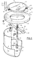
- la figure 3 est une vue en perspective éclatée à plus grande échelle des principaux composants de la partie inférieure de la soupape de la figure 2, et notamment du clapet de dépression ;
- la figure 4 est une vue en section axiale à plus grande échelle qui illustre des détails de réalisation de la figure 2 ;
- la figure 5 est une vue de dessous du clapet de dépression de la soupape représentée aux figures 2 et 3 sans la cuvette de récupération des écoulements.
Claims (15)
- Soupape de sécurité (10) pour une cuve destinée à contenir un fluide chimique ou alimentaire afin notamment de réaliser un dispositif de protection automatique au vide en cas de vidange d'une cuve étanche, éventuellement en combinaison avec un dispositif de protection automatique à la surpression lors du remplissage de la cuve, du type comportant un corps de soupape (16) comportant une paroi latérale (18) en forme de jupe globalement cylindrique d'axe vertical (A) qui est fermée à sa partie supérieure et à la partie inférieure (20) de laquelle est agencée une plaque annulaire horizontale inférieure (20) trouée centralement (36) et qui s'étend radialement vers l'intérieur du corps de soupape et dont la face supérieure (24) délimite un siège annulaire de clapet avec lequel coopère la face annulaire inférieure en vis-à-vis d'un corps mobile de clapet (32) en forme générale de plaque de fermeture du trou central (36) qui repose par gravité sur le siège de clapet (24) et qui est susceptible de se soulever automatiquement lorsque la pression à l'intérieur (40) du corps de soupape est inférieure à une valeur déterminée pour constituer un clapet de dépression (12),
caractérisée en ce que la plaque annulaire (20) forme un ensemble monobloc avec la jupe latérale (18) du corps de soupape (16), et en ce que le trou central (36) de la plaque annulaire et le corps de clapet (32) sont de forme générale ovale ou elliptique afin de permettre l'introduction du corps de clapet (32) de bas en haut à travers le trou central (36) en vue de sa mise en place lors de l'assemblage de la soupape (10). - Soupape de sécurité selon la revendication précédente, caractérisée en ce que la plaque annulaire (20) formant siège de clapet est soudée au bord d'extrémité inférieure (64) de la jupe annulaire (18) du corps de soupape (16).
- Soupape selon l'une quelconque des revendications précédentes, caractérisée en ce que ladite face supérieure (24) de la plaque annulaire formant siège de clapet (20) est une surface lisse sur laquelle vient porter un joint périphérique d'étanchéité (28) porté par le corps de clapet (32).
- Soupape selon la revendication précédente, caractérisée en ce que le corps de clapet (32) comporte une gorge périphérique (69) qui est ouverte radialement vers l'extérieur et verticalement vers le bas et qui reçoit le joint périphérique d'étanchéité (28, 68).
- Soupape selon l'une quelconque des revendications 3 ou 4, caractérisée en ce que la face inférieure (72) du corps de clapet (32) comporte une zone périphérique annulaire inférieure (70) d'appui du corps de clapet sur le siège (24), et en ce que le joint d'étanchéité (28, 68) comporte une lèvre inférieure d'étanchéité (66) qui porte sur le siège de clapet (24) lorsque ladite zone (70) est en appui.
- Soupape selon l'une quelconque des revendications précédentes, caractérisée en ce que le clapet comporte une tige centrale et axiale (82) de guidage des déplacements verticaux du corps de clapet (32) par rapport au siège de clapet (24), qui s'étend verticalement vers le bas et qui est reçue en coulissement axial dans une bague (88) de guidage portée par la plaque annulaire (20) formant siège de clapet.
- Soupape selon la revendication précédente, caractérisée en ce qu'elle comporte un bras inférieur transversal (90) de guidage du corps de clapet (32) qui s'étend diamétralement et dont les deux extrémités opposées (92) s'étendent chacune en regard d'une partie en vis-à-vis de la face inférieure (98) de la plaque annulaire (20) formant siège de clapet à laquelle elle est fixée, et en ce que le tronçon central du bras de guidage constitue ladite bague de guidage (88).
- Soupape selon la revendication précédente, caractérisée en ce qu'il est prévu des moyens d'indexation angulaire du corps de clapet (32) par rapport au siège de clapet (20, 24).
- Soupape selon la revendication précédente prise en combinaison avec l'une des revendications 6 ou 7, caractérisée en ce que la tige de guidage (82) est solidaire en rotation du corps de clapet (32), et en ce qu'il est prévu des moyens d'indexation (100, 102) angulaire de la tige de guidage (82) par rapport à la bague de guidage (88).
- Soupape selon l'une quelconque des revendications précédentes, caractérisée en ce que la face supérieure (76) du corps de clapet (32) est une surface plane lisse.
- Soupape selon l'une quelconque des revendications précédentes, caractérisée en ce que la partie supérieure du corps de soupape (16) est fermée par une paroi supérieure (56) réalisée en une seule pièce avec la jupe latérale (18).
- Soupape selon la revendication précédente, caractérisée en ce que la paroi supérieure (56) comporte un trou central (38) reliant le corps de soupape (16) à un clapet taré de surpression (14) rapporté à la partie supérieure de la soupape (10) et agencé à l'extérieur du corps (16) de soupape.
- Soupape selon la revendication précédente, caractérisée en ce que le clapet supérieur de surpression (14) comporte une plaque annulaire (22) délimitant un siège de soupape et qui est fixée à la paroi supérieure (56) du corps de soupape (16) par soudage.
- Soupape selon l'une quelconque des revendications précédentes, caractérisée en ce qu'elle comporte un organe (112, 114) de lavage et ou de rinçage de la soupape qui comporte notamment une buse de projection de liquide de lavage et/ou de rinçage qui est agencée centralement à l'intérieur (40) du corps de soupape (32), et/ou un filtre anti-insectes (106).
- Soupape selon l'une quelconque des revendications précédentes, caractérisée en ce que le corps de soupape (16) est une pièce de chaudronnerie, notamment en acier inoxydable.
Applications Claiming Priority (2)
| Application Number | Priority Date | Filing Date | Title |
|---|---|---|---|
| FR0009579 | 2000-07-21 | ||
| FR0009579A FR2812063B1 (fr) | 2000-07-21 | 2000-07-21 | Soupape de securite pour une cuve destinee a contenir un fluide chimique ou alimentaire |
Publications (2)
| Publication Number | Publication Date |
|---|---|
| EP1174650A1 true EP1174650A1 (fr) | 2002-01-23 |
| EP1174650B1 EP1174650B1 (fr) | 2005-09-07 |
Family
ID=8852774
Family Applications (1)
| Application Number | Title | Priority Date | Filing Date |
|---|---|---|---|
| EP01401866A Expired - Lifetime EP1174650B1 (fr) | 2000-07-21 | 2001-07-12 | Soupape de sécurité pour une cuve destinée à contenir un fluide chimique ou alimentaire |
Country Status (4)
| Country | Link |
|---|---|
| EP (1) | EP1174650B1 (fr) |
| AT (1) | ATE304139T1 (fr) |
| DE (1) | DE60113200D1 (fr) |
| FR (1) | FR2812063B1 (fr) |
Cited By (7)
| Publication number | Priority date | Publication date | Assignee | Title |
|---|---|---|---|---|
| RU2219407C1 (ru) * | 2002-05-06 | 2003-12-20 | Саратовское акционерное производственно-коммерческое открытое общество "Нефтемаш" - САПКОН | Дыхательный клапан |
| RU2223437C2 (ru) * | 2002-02-26 | 2004-02-10 | Харченко Владимир Петрович | Дыхательный клапан |
| RU2327921C1 (ru) * | 2006-11-03 | 2008-06-27 | Саратовское акционерное производственно-коммерческое открытое общество "НЕФТЕМАШ"-САПКОН | Дыхательный клапан для резервуара |
| RU2398150C1 (ru) * | 2009-07-20 | 2010-08-27 | Олег Савельевич Кочетов | Клапан предохранительный гидравлический |
| RU2449193C2 (ru) * | 2010-04-16 | 2012-04-27 | Общество с ограниченной ответственностью "Самарский завод нефтяного и резервуарного оборудования" | Способ нанесения уплотнительного соединения герметизации клапана |
| RU2472998C2 (ru) * | 2011-02-03 | 2013-01-20 | Олег Савельевич Кочетов | Предохранительный гидравлический клапан |
| RU2472999C2 (ru) * | 2011-02-03 | 2013-01-20 | Олег Савельевич Кочетов | Предохранительный огнезащитный клапан |
Families Citing this family (1)
| Publication number | Priority date | Publication date | Assignee | Title |
|---|---|---|---|---|
| RU2735121C2 (ru) * | 2018-10-05 | 2020-10-28 | Юрий Николаевич Скрипов | Самодействующий клапан |
Citations (5)
| Publication number | Priority date | Publication date | Assignee | Title |
|---|---|---|---|---|
| US2732856A (en) * | 1956-01-31 | Vacuum vent valve | ||
| US4257445A (en) * | 1978-10-26 | 1981-03-24 | Buildex Incorporated | Shielded vent port |
| US4259984A (en) * | 1978-10-31 | 1981-04-07 | Dover Corporation | Valve construction |
| US5048560A (en) * | 1989-12-12 | 1991-09-17 | L&J Engineering Inc. | Sealing valve assembly |
| WO1997048926A2 (fr) * | 1996-06-17 | 1997-12-24 | Guilherme Dos Santos | Soupape droite de surete |
-
2000
- 2000-07-21 FR FR0009579A patent/FR2812063B1/fr not_active Expired - Fee Related
-
2001
- 2001-07-12 DE DE60113200T patent/DE60113200D1/de not_active Expired - Lifetime
- 2001-07-12 EP EP01401866A patent/EP1174650B1/fr not_active Expired - Lifetime
- 2001-07-12 AT AT01401866T patent/ATE304139T1/de not_active IP Right Cessation
Patent Citations (5)
| Publication number | Priority date | Publication date | Assignee | Title |
|---|---|---|---|---|
| US2732856A (en) * | 1956-01-31 | Vacuum vent valve | ||
| US4257445A (en) * | 1978-10-26 | 1981-03-24 | Buildex Incorporated | Shielded vent port |
| US4259984A (en) * | 1978-10-31 | 1981-04-07 | Dover Corporation | Valve construction |
| US5048560A (en) * | 1989-12-12 | 1991-09-17 | L&J Engineering Inc. | Sealing valve assembly |
| WO1997048926A2 (fr) * | 1996-06-17 | 1997-12-24 | Guilherme Dos Santos | Soupape droite de surete |
Cited By (7)
| Publication number | Priority date | Publication date | Assignee | Title |
|---|---|---|---|---|
| RU2223437C2 (ru) * | 2002-02-26 | 2004-02-10 | Харченко Владимир Петрович | Дыхательный клапан |
| RU2219407C1 (ru) * | 2002-05-06 | 2003-12-20 | Саратовское акционерное производственно-коммерческое открытое общество "Нефтемаш" - САПКОН | Дыхательный клапан |
| RU2327921C1 (ru) * | 2006-11-03 | 2008-06-27 | Саратовское акционерное производственно-коммерческое открытое общество "НЕФТЕМАШ"-САПКОН | Дыхательный клапан для резервуара |
| RU2398150C1 (ru) * | 2009-07-20 | 2010-08-27 | Олег Савельевич Кочетов | Клапан предохранительный гидравлический |
| RU2449193C2 (ru) * | 2010-04-16 | 2012-04-27 | Общество с ограниченной ответственностью "Самарский завод нефтяного и резервуарного оборудования" | Способ нанесения уплотнительного соединения герметизации клапана |
| RU2472998C2 (ru) * | 2011-02-03 | 2013-01-20 | Олег Савельевич Кочетов | Предохранительный гидравлический клапан |
| RU2472999C2 (ru) * | 2011-02-03 | 2013-01-20 | Олег Савельевич Кочетов | Предохранительный огнезащитный клапан |
Also Published As
| Publication number | Publication date |
|---|---|
| DE60113200D1 (de) | 2005-10-13 |
| EP1174650B1 (fr) | 2005-09-07 |
| ATE304139T1 (de) | 2005-09-15 |
| FR2812063A1 (fr) | 2002-01-25 |
| FR2812063B1 (fr) | 2003-07-18 |
Similar Documents
| Publication | Publication Date | Title |
|---|---|---|
| EP0757007B1 (fr) | Bague de fixation à double indexation | |
| FR2768484A1 (fr) | Robinet de chasse du type a membrane et ensemble a element d'obturation pour ce robinet | |
| FR2669244A1 (fr) | Distributeur de produit, liquide a pateux, et embase pour un tel distributeur. | |
| EP1174650B1 (fr) | Soupape de sécurité pour une cuve destinée à contenir un fluide chimique ou alimentaire | |
| FR2502591A1 (fr) | Assemblage de liaison pour systemes a deux composantes | |
| EP2432707B1 (fr) | Bouchon anti-goutte a capuchon mobile rappele elastiquement | |
| WO2002034412A1 (fr) | Distributeur de produit fluide | |
| WO2005070560A1 (fr) | Organe de distribution de produit fluide et distributeur comprenant un tel organe | |
| EP1106795B1 (fr) | Filtre à liquide à purge automatique pour moteur à combustion interne | |
| FR2564503A1 (fr) | Dispositif de pulverisation pour sanitaire | |
| FR2792620A1 (fr) | Support de poche souple et distributeur comprenant un tel support | |
| FR2579193A1 (fr) | Robinet telescopique pour reservoir de machine automatique de remplissage de liquide | |
| FR2559135A1 (fr) | Distributeur-doseur d'un produit pateux | |
| FR2810302A1 (fr) | Dispositif de reprise d'air dynamique pour distributeur de produit liquide | |
| FR2952831A1 (fr) | Dispositif de filtre a huile et vehicule comportant un tel dispositif | |
| CA2338169A1 (fr) | Dispositif de distribution, notamment pour doseur de machine de remplissage, et doseur equipe d'un tel dispositif | |
| CH666503A5 (fr) | Dispositif pour distribuer une dose d'un produit liquide dans un reservoir de liquide, notamment un reservoir de chasse d'eau. | |
| FR2631935A1 (fr) | Bouchon-verseur en matiere synthetique | |
| EP3893637B1 (fr) | Couvercle pour cuve comprenant un event pourvu d'un flotteur en serie avec une chicane | |
| BE1007401A6 (fr) | Dispositif de bouchage d'une cuve, bouchon adapte et cuve equipee en consequence. | |
| EP0805719B1 (fr) | Pompe a clapet d'admission monobloc et ensemble de moulage d'un tel clapet | |
| BE892624A (fr) | Assemblage de liaison pour systemes a deux composantes | |
| FR2850958A1 (fr) | Dispositif de mise a l'air libre pour une citerne et citerne equipee dudit dispositif | |
| WO2026046940A1 (fr) | Dispositif de distribution de produit fluide comportant une pompe | |
| FR2816985A1 (fr) | Filtre a liquide a purge automatique pour moteur a combustion interne |
Legal Events
| Date | Code | Title | Description |
|---|---|---|---|
| PUAI | Public reference made under article 153(3) epc to a published international application that has entered the european phase |
Free format text: ORIGINAL CODE: 0009012 |
|
| AK | Designated contracting states |
Kind code of ref document: A1 Designated state(s): AT BE CH CY DE DK ES FI FR GB GR IE IT LI LU MC NL PT SE TR |
|
| AX | Request for extension of the european patent |
Free format text: AL;LT;LV;MK;RO;SI |
|
| 17P | Request for examination filed |
Effective date: 20020720 |
|
| AKX | Designation fees paid |
Free format text: AT BE CH CY DE DK ES FI FR GB GR IE IT LI LU MC NL PT SE TR |
|
| 17Q | First examination report despatched |
Effective date: 20040325 |
|
| GRAP | Despatch of communication of intention to grant a patent |
Free format text: ORIGINAL CODE: EPIDOSNIGR1 |
|
| GRAS | Grant fee paid |
Free format text: ORIGINAL CODE: EPIDOSNIGR3 |
|
| RAP1 | Party data changed (applicant data changed or rights of an application transferred) |
Owner name: SOCIETE NOUVELLE SERVINOX |
|
| GRAA | (expected) grant |
Free format text: ORIGINAL CODE: 0009210 |
|
| AK | Designated contracting states |
Kind code of ref document: B1 Designated state(s): AT BE CH CY DE DK ES FI FR GB GR IE IT LI LU MC NL PT SE TR |
|
| PG25 | Lapsed in a contracting state [announced via postgrant information from national office to epo] |
Ref country code: IT Free format text: LAPSE BECAUSE OF FAILURE TO SUBMIT A TRANSLATION OF THE DESCRIPTION OR TO PAY THE FEE WITHIN THE PRESCRIBED TIME-LIMIT;WARNING: LAPSES OF ITALIAN PATENTS WITH EFFECTIVE DATE BEFORE 2007 MAY HAVE OCCURRED AT ANY TIME BEFORE 2007. THE CORRECT EFFECTIVE DATE MAY BE DIFFERENT FROM THE ONE RECORDED. Effective date: 20050907 Ref country code: IE Free format text: LAPSE BECAUSE OF FAILURE TO SUBMIT A TRANSLATION OF THE DESCRIPTION OR TO PAY THE FEE WITHIN THE PRESCRIBED TIME-LIMIT Effective date: 20050907 Ref country code: AT Free format text: LAPSE BECAUSE OF FAILURE TO SUBMIT A TRANSLATION OF THE DESCRIPTION OR TO PAY THE FEE WITHIN THE PRESCRIBED TIME-LIMIT Effective date: 20050907 Ref country code: NL Free format text: LAPSE BECAUSE OF FAILURE TO SUBMIT A TRANSLATION OF THE DESCRIPTION OR TO PAY THE FEE WITHIN THE PRESCRIBED TIME-LIMIT Effective date: 20050907 Ref country code: GB Free format text: LAPSE BECAUSE OF FAILURE TO SUBMIT A TRANSLATION OF THE DESCRIPTION OR TO PAY THE FEE WITHIN THE PRESCRIBED TIME-LIMIT Effective date: 20050907 Ref country code: FI Free format text: LAPSE BECAUSE OF FAILURE TO SUBMIT A TRANSLATION OF THE DESCRIPTION OR TO PAY THE FEE WITHIN THE PRESCRIBED TIME-LIMIT Effective date: 20050907 |
|
| REG | Reference to a national code |
Ref country code: GB Ref legal event code: FG4D Free format text: NOT ENGLISH |
|
| REG | Reference to a national code |
Ref country code: CH Ref legal event code: EP |
|
| REG | Reference to a national code |
Ref country code: IE Ref legal event code: FG4D Free format text: LANGUAGE OF EP DOCUMENT: FRENCH |
|
| REF | Corresponds to: |
Ref document number: 60113200 Country of ref document: DE Date of ref document: 20051013 Kind code of ref document: P |
|
| PG25 | Lapsed in a contracting state [announced via postgrant information from national office to epo] |
Ref country code: DK Free format text: LAPSE BECAUSE OF FAILURE TO SUBMIT A TRANSLATION OF THE DESCRIPTION OR TO PAY THE FEE WITHIN THE PRESCRIBED TIME-LIMIT Effective date: 20051207 Ref country code: GR Free format text: LAPSE BECAUSE OF FAILURE TO SUBMIT A TRANSLATION OF THE DESCRIPTION OR TO PAY THE FEE WITHIN THE PRESCRIBED TIME-LIMIT Effective date: 20051207 Ref country code: SE Free format text: LAPSE BECAUSE OF FAILURE TO SUBMIT A TRANSLATION OF THE DESCRIPTION OR TO PAY THE FEE WITHIN THE PRESCRIBED TIME-LIMIT Effective date: 20051207 |
|
| PG25 | Lapsed in a contracting state [announced via postgrant information from national office to epo] |
Ref country code: DE Free format text: LAPSE BECAUSE OF FAILURE TO SUBMIT A TRANSLATION OF THE DESCRIPTION OR TO PAY THE FEE WITHIN THE PRESCRIBED TIME-LIMIT Effective date: 20051208 |
|
| PG25 | Lapsed in a contracting state [announced via postgrant information from national office to epo] |
Ref country code: ES Free format text: LAPSE BECAUSE OF FAILURE TO SUBMIT A TRANSLATION OF THE DESCRIPTION OR TO PAY THE FEE WITHIN THE PRESCRIBED TIME-LIMIT Effective date: 20051218 |
|
| PG25 | Lapsed in a contracting state [announced via postgrant information from national office to epo] |
Ref country code: PT Free format text: LAPSE BECAUSE OF FAILURE TO SUBMIT A TRANSLATION OF THE DESCRIPTION OR TO PAY THE FEE WITHIN THE PRESCRIBED TIME-LIMIT Effective date: 20060207 |
|
| NLV1 | Nl: lapsed or annulled due to failure to fulfill the requirements of art. 29p and 29m of the patents act | ||
| GBV | Gb: ep patent (uk) treated as always having been void in accordance with gb section 77(7)/1977 [no translation filed] |
Effective date: 20050907 |
|
| REG | Reference to a national code |
Ref country code: IE Ref legal event code: FD4D |
|
| PLBE | No opposition filed within time limit |
Free format text: ORIGINAL CODE: 0009261 |
|
| STAA | Information on the status of an ep patent application or granted ep patent |
Free format text: STATUS: NO OPPOSITION FILED WITHIN TIME LIMIT |
|
| PG25 | Lapsed in a contracting state [announced via postgrant information from national office to epo] |
Ref country code: LI Free format text: LAPSE BECAUSE OF NON-PAYMENT OF DUE FEES Effective date: 20060731 Ref country code: BE Free format text: LAPSE BECAUSE OF NON-PAYMENT OF DUE FEES Effective date: 20060731 Ref country code: CH Free format text: LAPSE BECAUSE OF NON-PAYMENT OF DUE FEES Effective date: 20060731 Ref country code: MC Free format text: LAPSE BECAUSE OF NON-PAYMENT OF DUE FEES Effective date: 20060731 |
|
| 26N | No opposition filed |
Effective date: 20060608 |
|
| REG | Reference to a national code |
Ref country code: CH Ref legal event code: PL |
|
| BERE | Be: lapsed |
Owner name: SOC. NOUVELLE SERVINOX Effective date: 20060731 |
|
| PG25 | Lapsed in a contracting state [announced via postgrant information from national office to epo] |
Ref country code: TR Free format text: LAPSE BECAUSE OF FAILURE TO SUBMIT A TRANSLATION OF THE DESCRIPTION OR TO PAY THE FEE WITHIN THE PRESCRIBED TIME-LIMIT Effective date: 20050907 Ref country code: LU Free format text: LAPSE BECAUSE OF NON-PAYMENT OF DUE FEES Effective date: 20060712 |
|
| PG25 | Lapsed in a contracting state [announced via postgrant information from national office to epo] |
Ref country code: CY Free format text: LAPSE BECAUSE OF FAILURE TO SUBMIT A TRANSLATION OF THE DESCRIPTION OR TO PAY THE FEE WITHIN THE PRESCRIBED TIME-LIMIT Effective date: 20050907 |
|
| REG | Reference to a national code |
Ref country code: FR Ref legal event code: PLFP Year of fee payment: 15 |
|
| REG | Reference to a national code |
Ref country code: FR Ref legal event code: PLFP Year of fee payment: 16 |
|
| REG | Reference to a national code |
Ref country code: FR Ref legal event code: PLFP Year of fee payment: 17 |
|
| REG | Reference to a national code |
Ref country code: FR Ref legal event code: PLFP Year of fee payment: 18 |
|
| PGFP | Annual fee paid to national office [announced via postgrant information from national office to epo] |
Ref country code: FR Payment date: 20200731 Year of fee payment: 20 |