EP1174647A1 - Boíte de vitesses comportant un dispositif de crabotage à échappement - Google Patents
Boíte de vitesses comportant un dispositif de crabotage à échappement Download PDFInfo
- Publication number
- EP1174647A1 EP1174647A1 EP01401813A EP01401813A EP1174647A1 EP 1174647 A1 EP1174647 A1 EP 1174647A1 EP 01401813 A EP01401813 A EP 01401813A EP 01401813 A EP01401813 A EP 01401813A EP 1174647 A1 EP1174647 A1 EP 1174647A1
- Authority
- EP
- European Patent Office
- Prior art keywords
- fork
- forks
- actuator
- finger
- additional
- Prior art date
- Legal status (The legal status is an assumption and is not a legal conclusion. Google has not performed a legal analysis and makes no representation as to the accuracy of the status listed.)
- Withdrawn
Links
- 230000008878 coupling Effects 0.000 title description 4
- 238000010168 coupling process Methods 0.000 title description 4
- 238000005859 coupling reaction Methods 0.000 title description 4
- 230000005540 biological transmission Effects 0.000 title description 2
- 230000007935 neutral effect Effects 0.000 description 19
- 230000008859 change Effects 0.000 description 12
- 238000006073 displacement reaction Methods 0.000 description 2
- 244000236931 Cydonia oblonga Species 0.000 description 1
- 230000009467 reduction Effects 0.000 description 1
- 230000009466 transformation Effects 0.000 description 1
Images


Classifications
-
- F—MECHANICAL ENGINEERING; LIGHTING; HEATING; WEAPONS; BLASTING
- F16—ENGINEERING ELEMENTS AND UNITS; GENERAL MEASURES FOR PRODUCING AND MAINTAINING EFFECTIVE FUNCTIONING OF MACHINES OR INSTALLATIONS; THERMAL INSULATION IN GENERAL
- F16H—GEARING
- F16H63/00—Control outputs from the control unit to change-speed- or reversing-gearings for conveying rotary motion or to other devices than the final output mechanism
- F16H63/02—Final output mechanisms therefor; Actuating means for the final output mechanisms
- F16H63/08—Multiple final output mechanisms being moved by a single common final actuating mechanism
- F16H63/20—Multiple final output mechanisms being moved by a single common final actuating mechanism with preselection and subsequent movement of each final output mechanism by movement of the final actuating mechanism in two different ways, e.g. guided by a shift gate
-
- F—MECHANICAL ENGINEERING; LIGHTING; HEATING; WEAPONS; BLASTING
- F16—ENGINEERING ELEMENTS AND UNITS; GENERAL MEASURES FOR PRODUCING AND MAINTAINING EFFECTIVE FUNCTIONING OF MACHINES OR INSTALLATIONS; THERMAL INSULATION IN GENERAL
- F16H—GEARING
- F16H63/00—Control outputs from the control unit to change-speed- or reversing-gearings for conveying rotary motion or to other devices than the final output mechanism
- F16H63/02—Final output mechanisms therefor; Actuating means for the final output mechanisms
- F16H63/30—Constructional features of the final output mechanisms
-
- F—MECHANICAL ENGINEERING; LIGHTING; HEATING; WEAPONS; BLASTING
- F16—ENGINEERING ELEMENTS AND UNITS; GENERAL MEASURES FOR PRODUCING AND MAINTAINING EFFECTIVE FUNCTIONING OF MACHINES OR INSTALLATIONS; THERMAL INSULATION IN GENERAL
- F16H—GEARING
- F16H63/00—Control outputs from the control unit to change-speed- or reversing-gearings for conveying rotary motion or to other devices than the final output mechanism
- F16H63/02—Final output mechanisms therefor; Actuating means for the final output mechanisms
- F16H63/08—Multiple final output mechanisms being moved by a single common final actuating mechanism
- F16H63/20—Multiple final output mechanisms being moved by a single common final actuating mechanism with preselection and subsequent movement of each final output mechanism by movement of the final actuating mechanism in two different ways, e.g. guided by a shift gate
- F16H2063/208—Multiple final output mechanisms being moved by a single common final actuating mechanism with preselection and subsequent movement of each final output mechanism by movement of the final actuating mechanism in two different ways, e.g. guided by a shift gate using two or more selecting fingers
-
- F—MECHANICAL ENGINEERING; LIGHTING; HEATING; WEAPONS; BLASTING
- F16—ENGINEERING ELEMENTS AND UNITS; GENERAL MEASURES FOR PRODUCING AND MAINTAINING EFFECTIVE FUNCTIONING OF MACHINES OR INSTALLATIONS; THERMAL INSULATION IN GENERAL
- F16H—GEARING
- F16H63/00—Control outputs from the control unit to change-speed- or reversing-gearings for conveying rotary motion or to other devices than the final output mechanism
- F16H63/02—Final output mechanisms therefor; Actuating means for the final output mechanisms
- F16H63/30—Constructional features of the final output mechanisms
- F16H2063/3086—Shift head arrangements, e.g. forms or arrangements of shift heads for preselection or shifting
-
- F—MECHANICAL ENGINEERING; LIGHTING; HEATING; WEAPONS; BLASTING
- F16—ENGINEERING ELEMENTS AND UNITS; GENERAL MEASURES FOR PRODUCING AND MAINTAINING EFFECTIVE FUNCTIONING OF MACHINES OR INSTALLATIONS; THERMAL INSULATION IN GENERAL
- F16H—GEARING
- F16H63/00—Control outputs from the control unit to change-speed- or reversing-gearings for conveying rotary motion or to other devices than the final output mechanism
- F16H63/02—Final output mechanisms therefor; Actuating means for the final output mechanisms
- F16H63/30—Constructional features of the final output mechanisms
- F16H63/32—Gear shift yokes, e.g. shift forks
Definitions
- the invention relates to a vehicle gearbox automobile.
- the invention relates more particularly to a box of motor vehicle speeds, of the type comprising at least two parallel shafts between which are arranged at least four gears each consisting of a idler gear meshing permanently with an associated fixed gear, and of the type in which each idler gear is likely to be dogged on its tree through one end of a fork of control whose other free end has a fork contact, which is likely to receive at least one finger which extends radially from the cylindrical body of an actuator, which is likely to be ordered sliding along its axis to select at least one fork associated with a fork, then to be ordered to rotate around its axis to push the fork in a direction of mobility of the range and in a certain direction and thus initiate the relationship associated with the fork and the determined direction.
- actuation of the gear change is operated in accordance with a gear change.
- the selection of reports can be obtained by moving the lever relative to the grid transversely to a selection position of at least one report, and the commitment of this report can be obtained by moving the lever longitudinally in a direction determined at from said selection position.
- Such grids include pairs of reports which are arranged transversely on the side and on the other from a central point called "neutral".
- the reports of each pair of reports are arranged longitudinally, from side and on the other side of a transverse selection line passing through the central point of neutral, along a so-called clutch line.
- the grid also includes independent reports arranged transversely on either side of the neutral position.
- a forward gear report in particular the fifth forward gear report and the reverse are offset at the cross ends of the wire rack.
- two interconnection lines are associated with these only reports.
- Such a gear change grid is particularly bulky transversely.
- Such grids contain only pairs of reports which are arranged transversely on either side of the central point called "neutral". Reports of each pair are arranged longitudinally, on either side of the line selection cross passing through the point's central point dead, following an associated line called interconnection.
- At least one ratio of forward gear and the forward gear are arranged on a same interconnection line. So, for example, for a box five forward gears, the reverse gear is conventionally placed on the same dog clutch line as the first forward gear or fifth gear forward.
- the fifth forward gear and the reverse gear are placed on the same line of clutching of the gear change grid and correspond to a determined transverse position of the lever on the selection line. Therefore, the dog clutch position one of these reports does differ from the dog clutch position the other report only by the opposite position of the actuator along of the same dog clutch line. So, for example, if the actuator is a rotary and sliding actuator, whose sliding allows the selection of forks and whose rotation allows interconnection of reports, interconnection of the fifth report of forward does not differ from dog clutch reverse gear only by the direction of rotation of the actuator. Therefore, it is important to be able to decouple the actuator from a power fork operate the other fork.
- this coupling device makes it possible to couple the range of the report which must be clutched to the actuator prior to the interconnection of the report in question, and / or uncoupling the gear from the gear which should not be clutched to the actuator prior to clutching the desired gear.
- the invention proposes a gearbox of the type described above in which the actuator is capable of directly controlling each forks of the gearbox.
- the invention provides a gearbox of the type described above, characterized in that the actuator has three fingers of which a first finger is likely to order the interconnection of at least two idler gears associated with at least two independent main ranges, including second and third fingers are each associated respectively the interconnection of idler gears associated with two additional independent forks, and in that the box includes mechanical exhaust means intended for allow other fingers, when a finger operates a fork determined to clutch an associated idler gear, to get out of forks other than the specified fork.
- FIGS. 1 and 2 show grids 10 and 12 of shifting of a motor vehicle intended for guide a lever (not shown) of gear changes a manual gearbox with five gear ratios forward direction identified in the figures by the numbers “1", “2", “3”, “4", and "5" and a reverse gear identified by the letters "AR".
- the selection of the reports can be obtained by moving the lever relative to the grid according to the transverse direction "T" to a selection position of at least minus one report, and engagement of a report can be obtained by moving the lever in the longitudinal direction "L” in a direction determined from said selection position.
- Such grids 10 include pairs of reports, - here the pair of reports “1” and “2” and the pair of ratios “3” and “4" which are arranged transversely from on either side of a central point "PM” called “neutral”.
- the reports of each pair of reports are arranged longitudinally in the direction "L”, on either side of a transverse "S” line of selection passing through the central point "PM” in neutral, and are also aligned along a line “C” called interconnection.
- a forward gear report for example the fifth forward gear "5", and the forward gear rear 'AR' are offset transversely at the ends of the grid 10.
- a line “C” of interconnection is specifically associated with each of these, the other "1" reports, "2", “3", “4" being associated in pairs with a line “C” of clean dog clutch.
- Such a gear change grid 10 is particularly bulky transversely.
- such grids 12 only have pairs of ratios which are arranged transversely on either side of the central point PM says “neutral”.
- the reports of each pair are arranged longitudinally on the same dog clutch line "C" following the direction "L”, on both sides of the transverse line “S” of selection through the neutral center "PM”.
- the grid 12 has three pairs of reports, one pair for "1" reports and "2", a pair for the ratios "3" and "4", and a pair for the ratios "5" and "AR" reports.
- the device 14 is intended to ensure the gear change command of a gearbox (not shown) of a motor vehicle.
- the gearbox has at least two parallel shafts (not shown) between which are arranged at least four gears which are each consisting of a idler gear permanently meshing with an associated fixed gear (not shown).
- Each idler gear is likely to be dogged on his tree through a end of a control fork with the other end free has a contact fork, which is likely to receive at least one finger which extends radially from the cylindrical body 16 of an actuator 18.
- the actuator 16 can be controlled by sliding along its X axis to select at least one fork associated with a fork, then to be ordered in rotation around its X axis to push the fork along a direction of mobility of the fork, and in a determined direction, in order to engage the ratio associated with the range and the meaning determined.
- the actuator 18 comprises a first finger 20, second finger 22 and third finger 24 which extend from its cylindrical body 16.
- the first finger 20 is capable of controlling the interconnection of at least two idler gears associated with at least two independent main ranges 26 and 28 of which sees the free ends 30 and 32 in Figure 3.
- the first finger is likely to command the interconnection of first and second gears forward through main fork 26 and order the interconnection of a third and a fourth gear forward through the main fork 28.
- the second finger 22 is associated with the clutching of a pinion crazy associated with an additional independent fork 34 whose free end can be seen 36.
- the fork additional 34 is for example associated with the interconnection of a fifth forward gear.
- the third finger 24 is associated with the clutching of a pinion crazy associated with an additional independent fork 38 the free end of which can be seen 40.
- the fork additional 38 is for example associated with the interconnection of a reverse gear.
- the device 14 which has been shown in Figure 3 is associated with the control of a box of gears with five forward gears but it will understood that the same device 14 could be applied to the control of a gearbox comprising a number lower or higher gear ratios, these being in any event ordered through the first finger 20 and an associated main fork.
- device 10 would include a fork main more.
- each fork by finger corresponding is achieved by means of a fork integral with each fork. More particularly, the free ends 30, 32, 36 and 40 of the forks 26, 28, 34 and 38 have the shape of parallel plates which are movable relative to each other others in parallel planes in a direction Y which is transverse to the axial direction X of the actuator 18. The edges plates have cutouts defining the forks in which the fingers are received. So the free ends 30, 32, 36 and 40 of the ranges 26, 28, 34 and 38 include cutouts delimiting forks 42, 44, 46 and 48.
- Each cut of the forks 42, 44, 46 or 48 has substantially the shape of a U which is turned towards the outside of the corresponding plate and the end of each finger 20, 22 or 24 has a key 50, 52 and 54 associated in the form of a portion cylinder whose axis is parallel to the X axis of the actuator and whose diameter corresponds to the spacing of the branches of the U of the associated fork 42, 44, or 46. So each finger 20, 22 or 24 can be without play between the legs of the fork 42, 44, or 46 associated during at least part of the rotation stroke of the actuator around the X axis, so as to allow the drive of the range 30, 32, 34 or 38 associated in dog clutch position and its return to the rest position. This configuration will be explained in more detail with reference to Figures 4 to 17.
- the plates of the main forks 26 and 28 and the additional fork plate 34 are mounted sliding in a direction Y which is perpendicular to the axis X of rotation of the actuator 16, and the plate of the fork additional 38 is pivotally mounted about a Z axis which is offset parallel to the axis X of rotation of the actuator 16.
- the first finger 20 is associated with the control of the plates sliding forks 26 and 28, while the second and third fingers 22 and 24 are respectively associated with sliding and pivoting fork controls additional 34 and 38.
- the box comprises means exhaust mechanics which are intended to allow other fingers, when a finger 20, 22 or 24 actuates a fork 42, 44, 46 or 48 determined to clutch an associated idler gear, get out of forks other than the specified fork.
- the means exhaust mechanics first include at least one axial clearance "J" of exhaust which is arranged, in the direction X sliding of the actuator, between all the plates main forks 26 and 28 and all the plates additional ranges 34 and 38, the value of which corresponds to the maximum value of the dimensions, taken according to the axial direction X of the actuator, which is likely to occupy all the plates of the main ranges 26 and 28 or all the plates of the additional forks 34 or 38.
- the first finger 20 cannot be received in either of the forks 42 or 44 of the main forks 26 or 28 as soon as the second fingers 22 and third fingers 24 are both located axially at the forks 46 and 48 of the additional ranges 34 and 38, and vice versa.
- the second and third fingers 22 and 24 are positioned axially between all of ranges 26 and 28 and all of forks 34 and 38, so that they cannot clutch any report.
- the movement of the actuator 16 simultaneously positions the second and third fingers 22 and 24 opposite the associated forks 34 and 38, the first finger 20 is positioned axially between all of the forks 26 and 28 and all of the forks 34 and 38, so that it cannot dogging no reports.
- This configuration is a part means for selecting the reports of the gearbox.
- the exhaust means comprise an angle " ⁇ " called the exhaust angle, taken in a plane transverse to the axial direction of the actuator, between the general direction D 22 of the second finger 22 and the general direction D 24 of the third finger 24, which is less than an angle " ⁇ " called rest which is formed, in the rest position of the additional forks 34 and 38 for which no gear is engaged, by the general directions D 46 and D 48 of the U-shaped forks of the additional forks 34 and 38.
- This exhaust configuration allows that when rotation of the actuator 18, the second finger 22 leaves the fork 46 of the additional range 34 associated as soon as the third finger 24 comes into contact with at least one branch of the fork 48 in U of the associated additional fork 38, and reciprocally.
- this configuration allows the finger to escape 22 or finger 24, selectively as a function of the direction of rotation the actuator around its X axis, outside of the fork 46 or 48 corresponding.
- the actuator 18 In the angular neutral position of the actuator which has been shown in Figure 3 and which is also shown in Figure 5, the actuator 18 is movable along its axis X along three gear selection positions.
- the actuator 16 In a first selection position which is shown in Figure 5, the actuator 16 is positioned axially along its X axis so that the first finger 20 is received in the fork 42 of the fork 26.
- the actuator 16 is positioned axially along its X axis so that the first finger 20 is received in the fork 44 of the fork 28.
- the second finger 22 and third finger 24 are located in the clearance J between the set of plates of the main forks 26, 28 and the set of plates of the additional forks 34 and 38, and so they cannot participate in dogging.
- the rotation of the actuator 18 in one direction or the other, from one of these two positions, is likely to cause selective interconnection of one of the first four reports of transmission of the gearbox.
- the main fork 26 is associated with the first and third forward gears
- the main fork 28 is associated with the second and fourth forward gear.
- the rotation of the actuator 16 causes a sliding of the plate considered in the direction Y.
- the transformation of the movement of rotation into movement of sliding is made possible by the cylinder configuration of the key 50 of the first finger 20 which cooperates with the edges in U of forks 42 or 44.
- the actuator 16 is positioned axially along its X axis so that the second finger 22 and the third finger 24 are received simultaneously and respectively in the fork 46 of the fork additional 34 and in the fork 48 of the fork additional 38.
- the first finger 20 is located in clearance J between the plates of the main forks 26, 28 and the set of plates of the additional forks 34 and 38, and in this way can not participate in the interconnection.
- one face 52a of the second finger 22, facing the X axis is in contact with a branch 46a of the fork 46 of additional fork 34, while one side 52b of the second finger 22, facing the axis Z, is free.
- a face 54b of the third finger 24, facing the Z axis is in contact with a branch 48b of the fork 48 of the additional fork 38, while that a face 54a of the third finger 24, facing the X axis, is free.
- the rotation of the actuator 18 in one direction or the other is likely to cause selective dogging of the fifth forward gear or reverse gear.
- the face 52b of the button 52 of the finger 22 comes in contact with a face 46b of the fork 46 of the fork 34 and allows its sliding training.
- the rotation of the actuator 18 clockwise is then transformed into a sliding movement according to the direction Y of the fork 34, which allows for example the clutching of the fifth forward gear ratio of the gearbox speeds.
- key 54 may escape of the fork 48 of the additional fork 38 because the general direction of the fork 48 in U of the pivoting plate of the fork 38 cuts the axis Z of rotation of said plate pivoting, and because the angle " ⁇ " of exhaust between the second finger 22 and third finger 24 is less than the angle " ⁇ " of rest formed by the general directions of the U-shaped forks additional forks 34 and 38. This arrangement provides a possibility of releasing the button 54 of finger 24.
- the face 54a of the button 54 of the finger 24 comes in contact with a face 48a of the fork 48 of the fork 38 and allows it to rotate about the Z axis.
- the rotation of the actuator 18 anti-clockwise is then transformed into a rotational movement around the Z axis clockwise, which allows for example the dog clutch reverse gear ratio.
- key 52 may escape of the fork 46 of the additional fork 34 because the branch 46b of the U-shaped fork 46 which is turned towards the side of the Z axis of rotation of the swivel plate is shorter than the other branch 46a of said fork 46 to provide a clearance on the edge of the fork sliding plate 34, and because the angle " ⁇ " of exhaust between the second finger 22 and third finger 24 is less than the angle " ⁇ " of rest formed by the general directions of the U-shaped forks of the forks additional 34 and 38. This arrangement provides a possibility to release the button 52 of finger 22.
- the invention advantageously makes it possible to produce a simple, reliable and inexpensive control of dog clutching reports of a gearbox.
Landscapes
- Engineering & Computer Science (AREA)
- General Engineering & Computer Science (AREA)
- Mechanical Engineering (AREA)
- Gear-Shifting Mechanisms (AREA)
Abstract
Description
- les extrémités libres des fourchettes présentent la forme de plaques parallèles qui sont mobiles les unes par rapport aux autres dans des plans parallèles transversalement par rapport à la direction axiale de l'actionneur et aux bords desquelles sont agencées des découpes délimitant les fourches dans lesquelles sont reçus les doigts,
- les moyens mécaniques d'échappement comportent au moins un jeu axial d'échappement qui est agencé, suivant la direction de coulissement de l'actionneur, entre l'ensemble des plaques des fourchettes principales et l'ensemble des plaques des fourchettes supplémentaires et dont la valeur correspond à la valeur maximale de l'encombrement, pris suivant la direction axiale de l'actionneur, qu'est susceptible d'occuper l'ensemble des plaques des fourchettes principales ou l'ensemble des plaques des fourchettes supplémentaires, et qui est destiné à ce que le premier doigt ne puisse être reçu dans l'une ou l'autre des fourches des fourchettes principales dès lors que les deuxième et troisième doigts sont tous deux situés axialement au niveau des fourches des fourchettes supplémentaires, et réciproquement,
- les plaques des fourchettes principales et une des plaques des fourchettes supplémentaires sont montées coulissantes suivant une direction perpendiculaire à l'axe de rotation de l'actionneur et l'autre plaque des fourchettes supplémentaires est montée pivotante autour d'un axe qui est décalé parallèlement à l'axe de rotation de l'actionneur,
- chaque découpe présente sensiblement la forme d'un U et en ce que l'extrémité de chaque doigt comporte une touche en forme de portion de cylindre dont l'axe est parallèle à l'axe de l'actionneur et dont le diamètre correspond à l'écartement des branches du U de la fourche associée, pour que chaque doigt soit reçu sans jeu entre les branches de la fourche associée pendant au moins une partie de la course de rotation de l'actionneur, de manière à permettre l'entraínement de la fourchette associée en position de crabotage et son rappel en position de repos,
- les deuxième et troisième doigts sont respectivement associés aux commandes des plaques coulissante et pivotante des fourchettes supplémentaires,
- les moyens d'échappement comportent:
- un angle dit d'échappement, pris dans un plan transversal à la direction axiale de l'actionneur, entre les deuxième et troisième doigts, qui est inférieur à un angle dit de repos qui est formé, dans la position de repos des fourchettes supplémentaires pour laquelle aucun rapport n'est engagé, par les directions générales des fourches en U des fourchettes supplémentaires, et
- une configuration dite d'échappement des fourches
en U des fourchettes supplémentaires, selon laquelle :
- la direction générale de la fourche en U de la plaque pivotante coupe l'axe de rotation de ladite plaque pivotante, et
- la branche (46b) de la fourche (46) en U de la plaque coulissante qui est tournée du côté de l'axe (Z) de rotation de la plaque pivotante est plus courte que l'autre branche (46a) de ladite fourche (46) pour fournir un dégagement sur le bord de ladite plaque coulissante, de manière que, lors de la rotation de l'actionneur, le deuxième doigt quitte la fourche de la fourchette supplémentaire associée dès lors que le troisième doigt vient au contact d'au moins une branche de la fourche en U de la fourchette supplémentaire associée, et réciproquement.
- la figure 1 est une représentation schématique d'une grille de changement de vitesses dite "en chandelier" ;
- la figure 2 est une représentation schématique d'une grille de changement de vitesses dite "en H" ;
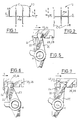
- la figure 3 est une vue en perspective de l'actionneur et des fourchettes d'une boíte de vitesses selon l'invention ;
- la figure 4 est une vue en coupe par le plan B-B de la figure 3 représentant l'agencement des doigts des fourchettes supplémentaires en position de repos de l'actionneur ;
- les figures 5 à 7 sont des vues en coupe par le plan A-A de la figure 3 représentant une position de point mort de l'actionneur et deux positions opposées de l'actionneur dans lesquelles le premier doigt actionne une fourchette principale ;
- la figure 8 est une vue en coupe par le plan B-B de la figure 3 représentant une position de point mort de l'actionneur dans laquelle les deuxième et troisième doigts sont reçus dans leurs fourchettes supplémentaires respectives ;
- la figure 9 est une vue en coupe par le plan C-C de la figure 3 représentant une position de point mort de l'actionneur dans laquelle les deuxième et troisième doigts sont reçus dans leurs fourchettes supplémentaires respectives ;
- la figure 10 est une vue de détail en section par le plan B-B de la figure 3 représentant, selon la position de point mort de l'actionneur représentée à la figure 8, la position du deuxième doigt dans la fourche de la fourchette supplémentaire associée ;
- la figure 11 est une vue de détail en section par le plan C-C de la figure 3 représentant, selon la position de point mort de l'actionneur représentée à la figure 8, la position du troisième doigt dans la fourche de la fourchette supplémentaire associée ;
- la figure 12 est une vue en coupe par le plan B-B de la figure 3 représentant une position de l'actionneur dans laquelle le deuxième doigt actionne la fourchette supplémentaire associée ;
- la figure 13 est une vue de détail en section par le plan B-B de la figure 3 représentant la position de l'actionneur selon la figure 12 dans laquelle le deuxième doigt actionne la fourchette supplémentaire associée ;
- la figure 14 est une vue de détail en section par le plan C-C de la figure 3 représentant la position de l'actionneur selon la figure 12 dans laquelle le troisième doigt s'échappe de la fourchette supplémentaire associée ;
- la figure 15 est une vue en coupe par le plan C-C de la figure 3 représentant une position de l'actionneur dans laquelle le troisième doigt actionne la fourchette supplémentaire associée ;
- la figure 16 est une vue de détail en section par le plan C-C de la figure 3 représentant la position de l'actionneur selon la figure 15 dans laquelle le troisième doigt actionne la fourchette supplémentaire associée ; et
- la figure 17 est une vue de détail en section par le plan B-B de la figure 3 représentant la position de l'actionneur selon la figure 15 dans laquelle le deuxième doigt s'échappe de la fourchette supplémentaire associée ;
- la direction générale de la fourche 48 en U de la plaque pivotante de la fourchette 38 coupe l'axe Z de rotation de ladite plaque pivotante, et
- la branche 46b de la fourche 46 en U de la plaque coulissante qui est tournée du côté de l'axe Z de rotation de la plaque pivotante est plus courte que l'autre branche 46a de ladite fourche 46 pour fournir un dégagement sur le bord de ladite plaque coulissante,
Claims (7)
- Boíte de vitesses de véhicule automobile, du type comportant au moins deux arbres parallèles entre lesquels sont agencés au moins quatre engrenages constitués chacun d'un pignon fou engrenant en permanence avec un pignon fixe associé, et du type dans lequel chaque pignon fou est susceptible d'être craboté sur son arbre par l'intermédiaire d'une extrémité d'une fourchette (26, 28, 34, 38) de commande dont l'autre extrémité libre (30, 32, 36, 40) comporte une fourche (42, 44, 46, 48) de contact, qui est susceptible de recevoir au moins un doigt (20, 22, 24) qui s'étend radialement à partir du corps cylindrique (16) d'un actionneur (18), qui est susceptible d'être commandé en coulissement le long de son axe (X) pour sélectionner au moins une fourche (42, 44, 46, 48) associée à une fourchette (26, 28, 34, 38), puis d'être commandé en rotation autour de son axe (X) pour pousser la fourche (42, 44, 46, 48) suivant une direction de mobilité de la fourchette (26, 28, 34, 38) et dans un sens déterminé et engager ainsi le rapport associé à la fourche (42, 44, 46, 48) et au sens déterminé, caractérisée en ce que l'actionneur comporte trois doigts (20, 22, 24) dont un premier doigt (20) est susceptible de commander le crabotage d'au moins deux pignons fous associés à au moins deux fourchettes principales (26, 28) indépendantes et dont des deuxième (22) et troisième (24) doigts sont chacun associés respectivement au crabotage de pignons fous associés à deux fourchettes supplémentaires (34, 38) indépendantes, et en ce que la boíte comporte des moyens mécaniques d'échappement destinés à permettre aux autres doigts, lorsqu'un doigt actionne une fourche déterminée pour craboter un pignon fou associé, de sortir des fourches autres que la fourche déterminée.
- Boíte de vitesses selon la revendication précédente, caractérisée en ce que les extrémités libres (30, 32, 36, 40) des fourchettes (26, 28, 34, 38) présentent la forme de plaques parallèles qui sont mobiles les unes par rapport aux autres dans des plans parallèles transversalement par rapport à la direction axiale (X) de l'actionneur (18) et aux bords desquelles sont agencées des découpes délimitant les fourches (42, 44, 46, 48) dans lesquelles sont reçus les doigts (20, 22, 24).
- Boíte de vitesses selon la revendication précédente, caractérisée en ce que les moyens mécaniques d'échappement comportent au moins un jeu axial (J) d'échappement qui est agencé, suivant la direction (X) de coulissement de l'actionneur (18), entre l'ensemble des plaques des fourchettes principales (26, 28) et l'ensemble des plaques des fourchettes supplémentaires (34, 38) et dont la valeur correspond à la valeur maximale de l'encombrement, pris suivant la direction axiale (X) de l'actionneur, qu'est susceptible d'occuper l'ensemble des plaques des fourchettes principales (26, 28) ou l'ensemble des plaques des fourchettes supplémentaires (34, 38), et qui est destiné à ce que le premier doigt (20) ne puisse être reçu dans l'une ou l'autre des fourches (42, 44) des fourchettes principales (26, 28) dès lors que les deuxième (22) et troisième (24) doigts sont tous deux situés axialement au niveau des fourches (46, 48) des fourchettes supplémentaires (34, 38), et réciproquement.
- Boíte de vitesses selon l'une des revendications 2 ou 3, caractérisée en ce que les plaques des fourchettes principales (26, 28) et une des plaques des fourchettes supplémentaires (34) sont montées coulissantes suivant une direction (Y) perpendiculaire à l'axe (X) de rotation de l'actionneur (18) et en ce que l'autre plaque des fourchettes supplémentaires (38) est montée pivotante autour d'un axe (Z) qui est décalé parallèlement à l'axe de rotation (X) de l'actionneur (18).
- Boíte de vitesses selon l'une des revendications 2 à 4, caractérisée en ce que chaque découpe présente sensiblement la forme d'un U et en ce que l'extrémité de chaque doigt (20, 22, 24) comporte une touche (50, 52, 54) en forme de portion de cylindre dont l'axe est parallèle à l'axe (X) de l'actionneur (18) et dont le diamètre correspond à l'écartement des branches du U de la fourche (42, 44, 46, 48) associée, pour que chaque doigt (20, 22, 24) soit reçu sans jeu entre les branches de la fourche (42, 44, 46, 48) associée pendant au moins une partie de la course de rotation de l'actionneur (18), de manière à permettre l'entraínement de la fourchette (26, 28, 34, 38) associée en position de crabotage et son rappel en position de repos.
- Boíte de vitesses selon l'une des revendications 4 ou 5, caractérisée en ce que les deuxième (22) et troisième (24) doigts sont respectivement associés aux commandes des plaques coulissante et pivotante des fourchettes supplémentaires (34, 38).
- Boite de vitesses selon la revendication précédente prise en combinaison avec les revendications 4 et 5, caractérisée en ce que les moyens d'échappement comportent:un angle (α) dit d'échappement, pris dans un plan transversal à la direction axiale (X) de l'actionneur (18), entre les deuxième (22) et troisième (24) doigts, qui est inférieur à un angle (β) dit de repos qui est formé, dans la position de repos des fourchettes supplémentaires (34, 38) pour laquelle aucun rapport n'est engagé, par les directions générales (D46, D48) des fourches en U des fourchettes supplémentaires (46, 48), etune configuration dite d'échappement des fourches (46, 48) en U des fourchettes supplémentaires (34, 38), selon laquelle:la direction générale (D48) de la fourche (48) en U de la plaque pivotante coupe l'axe (Z) de rotation de ladite plaque pivotante, etla branche (46b) de la fourche (46) en U de la plaque coulissante qui est tournée du côté de l'axe (Z) de rotation de la plaque pivotante est plus courte que l'autre branche (46a) de ladite fourche (46) pour fournir un dégagement sur le bord de ladite plaque coulissante, de manière que, lors de la rotation de l'actionneur (18), le deuxième doigt (22) quitte la fourche (46) de la fourchette (34) supplémentaire associée dès lors que le troisième doigt (24) vient au contact d'au moins une branche de la fourche (48) en U de la fourchette supplémentaire (38) associée, et réciproquement.
Applications Claiming Priority (2)
| Application Number | Priority Date | Filing Date | Title |
|---|---|---|---|
| FR0009573A FR2812058B1 (fr) | 2000-07-21 | 2000-07-21 | Boite de vitesses comportant un dispositif de crabotage a echappement |
| FR0009573 | 2000-07-21 |
Publications (1)
| Publication Number | Publication Date |
|---|---|
| EP1174647A1 true EP1174647A1 (fr) | 2002-01-23 |
Family
ID=8852769
Family Applications (1)
| Application Number | Title | Priority Date | Filing Date |
|---|---|---|---|
| EP01401813A Withdrawn EP1174647A1 (fr) | 2000-07-21 | 2001-07-06 | Boíte de vitesses comportant un dispositif de crabotage à échappement |
Country Status (2)
| Country | Link |
|---|---|
| EP (1) | EP1174647A1 (fr) |
| FR (1) | FR2812058B1 (fr) |
Cited By (5)
| Publication number | Priority date | Publication date | Assignee | Title |
|---|---|---|---|---|
| US7581462B2 (en) | 2007-06-07 | 2009-09-01 | Mitsubishi Jidosha Kogyo Kabushiki Kaisha | Transmission |
| EP2003374A3 (fr) * | 2007-06-11 | 2009-12-16 | Mitsubishi Jidosha Kogyo Kabushiki Kaisha | Transmission |
| US20140216189A1 (en) * | 2013-02-01 | 2014-08-07 | Dana Automotive Systems Group, Llc | Gear Shift Mechanism |
| JP5630578B2 (ja) * | 2011-05-27 | 2014-11-26 | トヨタ自動車株式会社 | 車両用手動変速機の操作機構 |
| CN113531118A (zh) * | 2020-04-17 | 2021-10-22 | 浙江万里扬股份有限公司 | 换挡组件、换挡箱和车辆 |
Citations (4)
| Publication number | Priority date | Publication date | Assignee | Title |
|---|---|---|---|---|
| DE922508C (de) * | 1953-06-13 | 1955-01-17 | Zahnradfabrik Friedrichshafen | Schaltvorrichtung fuer Kraftfahrzeug-Wechselgetriebe |
| US4449418A (en) * | 1981-02-09 | 1984-05-22 | Nissan Motor Company, Limited | Gearshift device |
| EP0149020A2 (fr) * | 1983-10-21 | 1985-07-24 | IVECO FIAT S.p.A. | Dispositifs pour le changement de vitesse et pour la commande d'une transmission en particulier pour véhicules industriels |
| EP0418107A1 (fr) * | 1989-09-08 | 1991-03-20 | Automobiles Peugeot | Dispositif de commande d'une boîte de vitesses de véhicule automobile |
-
2000
- 2000-07-21 FR FR0009573A patent/FR2812058B1/fr not_active Expired - Fee Related
-
2001
- 2001-07-06 EP EP01401813A patent/EP1174647A1/fr not_active Withdrawn
Patent Citations (4)
| Publication number | Priority date | Publication date | Assignee | Title |
|---|---|---|---|---|
| DE922508C (de) * | 1953-06-13 | 1955-01-17 | Zahnradfabrik Friedrichshafen | Schaltvorrichtung fuer Kraftfahrzeug-Wechselgetriebe |
| US4449418A (en) * | 1981-02-09 | 1984-05-22 | Nissan Motor Company, Limited | Gearshift device |
| EP0149020A2 (fr) * | 1983-10-21 | 1985-07-24 | IVECO FIAT S.p.A. | Dispositifs pour le changement de vitesse et pour la commande d'une transmission en particulier pour véhicules industriels |
| EP0418107A1 (fr) * | 1989-09-08 | 1991-03-20 | Automobiles Peugeot | Dispositif de commande d'une boîte de vitesses de véhicule automobile |
Cited By (6)
| Publication number | Priority date | Publication date | Assignee | Title |
|---|---|---|---|---|
| US7581462B2 (en) | 2007-06-07 | 2009-09-01 | Mitsubishi Jidosha Kogyo Kabushiki Kaisha | Transmission |
| EP2003374A3 (fr) * | 2007-06-11 | 2009-12-16 | Mitsubishi Jidosha Kogyo Kabushiki Kaisha | Transmission |
| JP5630578B2 (ja) * | 2011-05-27 | 2014-11-26 | トヨタ自動車株式会社 | 車両用手動変速機の操作機構 |
| US20140216189A1 (en) * | 2013-02-01 | 2014-08-07 | Dana Automotive Systems Group, Llc | Gear Shift Mechanism |
| US9383008B2 (en) * | 2013-02-01 | 2016-07-05 | Dana Automotive Systems Group, Llc | Gear shift mechanism |
| CN113531118A (zh) * | 2020-04-17 | 2021-10-22 | 浙江万里扬股份有限公司 | 换挡组件、换挡箱和车辆 |
Also Published As
| Publication number | Publication date |
|---|---|
| FR2812058B1 (fr) | 2003-01-24 |
| FR2812058A1 (fr) | 2002-01-25 |
Similar Documents
| Publication | Publication Date | Title |
|---|---|---|
| EP2275719A1 (fr) | Boîte de vitesses comportant un moyen de blocage d'un arbre de sortie et véhicule comportant une telle boîte de vitesses | |
| FR2474718A1 (fr) | Ensemble a selecteur de boite de vitesses d'automobile du type a cardan et cables, et a dispositif de verrouillage de vitesse | |
| FR2944079A1 (fr) | Transmission a double embrayage a sept vitesses | |
| EP0293288A1 (fr) | Dispositif de commande d'une boîte de vitesses de véhicule automobile | |
| EP1308651B1 (fr) | Boíte de vitesses à sélection masquée | |
| FR2554254A1 (fr) | Mecanisme selecteur du rapport de transmission | |
| FR2803890A1 (fr) | Barillet de commande pour boite de vitesses et boite de vitesses equipees d'un tel barillet | |
| FR2924777A1 (fr) | Dispositif de commande interne de boite de vitesses | |
| FR2812058A1 (fr) | Boite de vitesses comportant un dispositif de crabotage a echappement | |
| EP1471282B1 (fr) | Boîte de vitesses compacte à deux embrayages | |
| EP1072824B1 (fr) | Boíte de vitesses compacte comportant des pieds basculants d'actionnement des fourchettes | |
| EP0737827B1 (fr) | Commande interne de boíte de vitesses avec dispositif de rappel d'organes de sélection | |
| EP1643168B1 (fr) | Dispositif de commande d'une boîte de vitesses pour véhicules automobiles | |
| EP2063154B1 (fr) | Dispositif de commande interne de boîte de vitesses d'un véhicule automobile | |
| EP1072823B1 (fr) | Tambour sélecteur de vitesses pour boíte de vitesses multiples de véhicules automobiles | |
| FR2862366A1 (fr) | Dispositif de commande d'un rapport d'une boite de vitesses. | |
| EP1141581B1 (fr) | Boite de vitesses compacte a deux arbres secondaires | |
| FR2878596A1 (fr) | Dispositif de commande interne d'une boite de vitesses pilotee a simple embrayage de vehicule automobile | |
| EP1022495B1 (fr) | Boíte de vitesses à marche arrière synchronisée | |
| FR2819569A1 (fr) | Dispositif de commande interne d'une boite de vitesses pour vehicule automobile | |
| EP2050988B1 (fr) | Dispositif de freinage d'un arbre moteur d'une boîte de vitesses, pour l'engagement d'un pignon de marche arrière | |
| FR2797018A1 (fr) | Boite de vitesses compacte | |
| FR2861447A1 (fr) | Boite de vitesse pour vehicule automobile. | |
| EP0708277A1 (fr) | Dispositif et procédé de commande de boîte de vitesses | |
| FR2661724A1 (fr) | Boite de vitesses pour vehicule, a commande perfectionnee. |
Legal Events
| Date | Code | Title | Description |
|---|---|---|---|
| PUAI | Public reference made under article 153(3) epc to a published international application that has entered the european phase |
Free format text: ORIGINAL CODE: 0009012 |
|
| AK | Designated contracting states |
Kind code of ref document: A1 Designated state(s): DE ES GB IT Kind code of ref document: A1 Designated state(s): AT BE CH CY DE DK ES FI FR GB GR IE IT LI LU MC NL PT SE TR |
|
| AX | Request for extension of the european patent |
Free format text: AL;LT;LV;MK;RO;SI |
|
| RAP1 | Party data changed (applicant data changed or rights of an application transferred) |
Owner name: RENAULT S.A.S. |
|
| 17P | Request for examination filed |
Effective date: 20020625 |
|
| AKX | Designation fees paid |
Free format text: DE ES GB IT |
|
| 17Q | First examination report despatched |
Effective date: 20030617 |
|
| STAA | Information on the status of an ep patent application or granted ep patent |
Free format text: STATUS: THE APPLICATION HAS BEEN WITHDRAWN |
|
| 18W | Application withdrawn |
Effective date: 20030929 |