EP1174479A1 - Hydrophilic member, method for preparation thereof, and coating agent and apparatus for preparation thereof - Google Patents
Hydrophilic member, method for preparation thereof, and coating agent and apparatus for preparation thereof Download PDFInfo
- Publication number
- EP1174479A1 EP1174479A1 EP00907972A EP00907972A EP1174479A1 EP 1174479 A1 EP1174479 A1 EP 1174479A1 EP 00907972 A EP00907972 A EP 00907972A EP 00907972 A EP00907972 A EP 00907972A EP 1174479 A1 EP1174479 A1 EP 1174479A1
- Authority
- EP
- European Patent Office
- Prior art keywords
- hydrophilic
- layer
- substrate
- metal oxide
- oxide particles
- Prior art date
- Legal status (The legal status is an assumption and is not a legal conclusion. Google has not performed a legal analysis and makes no representation as to the accuracy of the status listed.)
- Withdrawn
Links
- 239000011248 coating agent Substances 0.000 title claims description 139
- 238000000034 method Methods 0.000 title claims description 33
- 238000002360 preparation method Methods 0.000 title description 23
- 239000000758 substrate Substances 0.000 claims abstract description 181
- 239000000463 material Substances 0.000 claims abstract description 163
- 239000002245 particle Substances 0.000 claims abstract description 142
- XLYOFNOQVPJJNP-UHFFFAOYSA-N water Substances O XLYOFNOQVPJJNP-UHFFFAOYSA-N 0.000 claims abstract description 140
- 229910044991 metal oxide Inorganic materials 0.000 claims abstract description 103
- 150000004706 metal oxides Chemical class 0.000 claims abstract description 103
- 238000000576 coating method Methods 0.000 claims description 144
- 239000008199 coating composition Substances 0.000 claims description 142
- VYPSYNLAJGMNEJ-UHFFFAOYSA-N Silicium dioxide Chemical compound O=[Si]=O VYPSYNLAJGMNEJ-UHFFFAOYSA-N 0.000 claims description 108
- 238000010438 heat treatment Methods 0.000 claims description 46
- 239000000377 silicon dioxide Substances 0.000 claims description 46
- MCMNRKCIXSYSNV-UHFFFAOYSA-N Zirconium dioxide Chemical compound O=[Zr]=O MCMNRKCIXSYSNV-UHFFFAOYSA-N 0.000 claims description 42
- 229910052681 coesite Inorganic materials 0.000 claims description 42
- 229910052906 cristobalite Inorganic materials 0.000 claims description 42
- 229910052682 stishovite Inorganic materials 0.000 claims description 42
- 229910052905 tridymite Inorganic materials 0.000 claims description 42
- 229910052910 alkali metal silicate Inorganic materials 0.000 claims description 33
- 230000033228 biological regulation Effects 0.000 claims description 32
- 238000004140 cleaning Methods 0.000 claims description 31
- 238000001816 cooling Methods 0.000 claims description 31
- GWEVSGVZZGPLCZ-UHFFFAOYSA-N Titan oxide Chemical compound O=[Ti]=O GWEVSGVZZGPLCZ-UHFFFAOYSA-N 0.000 claims description 29
- 239000011521 glass Substances 0.000 claims description 25
- XOLBLPGZBRYERU-UHFFFAOYSA-N tin dioxide Chemical compound O=[Sn]=O XOLBLPGZBRYERU-UHFFFAOYSA-N 0.000 claims description 23
- NBIIXXVUZAFLBC-UHFFFAOYSA-N Phosphoric acid Chemical compound OP(O)(O)=O NBIIXXVUZAFLBC-UHFFFAOYSA-N 0.000 claims description 20
- 238000005498 polishing Methods 0.000 claims description 17
- 230000001681 protective effect Effects 0.000 claims description 17
- PNEYBMLMFCGWSK-UHFFFAOYSA-N aluminium oxide Inorganic materials [O-2].[O-2].[O-2].[Al+3].[Al+3] PNEYBMLMFCGWSK-UHFFFAOYSA-N 0.000 claims description 16
- 230000015572 biosynthetic process Effects 0.000 claims description 13
- KGBXLFKZBHKPEV-UHFFFAOYSA-N boric acid Chemical compound OB(O)O KGBXLFKZBHKPEV-UHFFFAOYSA-N 0.000 claims description 13
- 239000002243 precursor Substances 0.000 claims description 13
- 239000003513 alkali Substances 0.000 claims description 12
- 239000003795 chemical substances by application Substances 0.000 claims description 12
- 229910052593 corundum Inorganic materials 0.000 claims description 11
- 229910001845 yogo sapphire Inorganic materials 0.000 claims description 11
- 229910000147 aluminium phosphate Inorganic materials 0.000 claims description 10
- -1 woods Substances 0.000 claims description 10
- 239000004327 boric acid Substances 0.000 claims description 9
- 230000001105 regulatory effect Effects 0.000 claims description 9
- 239000011347 resin Substances 0.000 claims description 8
- 229920005989 resin Polymers 0.000 claims description 8
- 239000007921 spray Substances 0.000 claims description 8
- 230000003068 static effect Effects 0.000 claims description 8
- 229910010272 inorganic material Inorganic materials 0.000 claims description 7
- 239000011147 inorganic material Substances 0.000 claims description 7
- 239000002904 solvent Substances 0.000 claims description 7
- 239000000919 ceramic Substances 0.000 claims description 6
- 238000009826 distribution Methods 0.000 claims description 6
- 229910052751 metal Inorganic materials 0.000 claims description 6
- 239000002184 metal Substances 0.000 claims description 6
- 238000004519 manufacturing process Methods 0.000 claims description 5
- 229910001463 metal phosphate Inorganic materials 0.000 claims description 5
- 150000003016 phosphoric acids Chemical class 0.000 claims description 5
- 239000000243 solution Substances 0.000 claims description 5
- 239000011259 mixed solution Substances 0.000 claims description 4
- 239000000378 calcium silicate Substances 0.000 claims description 3
- 229910052918 calcium silicate Inorganic materials 0.000 claims description 3
- OYACROKNLOSFPA-UHFFFAOYSA-N calcium;dioxido(oxo)silane Chemical compound [Ca+2].[O-][Si]([O-])=O OYACROKNLOSFPA-UHFFFAOYSA-N 0.000 claims description 3
- 239000004568 cement Substances 0.000 claims description 3
- 239000007769 metal material Substances 0.000 claims description 3
- 150000002739 metals Chemical class 0.000 claims description 3
- 238000011144 upstream manufacturing Methods 0.000 claims description 3
- 239000000725 suspension Substances 0.000 claims description 2
- 239000012459 cleaning agent Substances 0.000 claims 3
- 239000002905 metal composite material Substances 0.000 claims 2
- 239000013212 metal-organic material Substances 0.000 claims 2
- 230000005855 radiation Effects 0.000 claims 1
- 230000008021 deposition Effects 0.000 abstract description 17
- 239000002689 soil Substances 0.000 abstract description 17
- 238000012360 testing method Methods 0.000 description 112
- 238000011156 evaluation Methods 0.000 description 27
- 239000000126 substance Substances 0.000 description 27
- 239000007789 gas Substances 0.000 description 25
- 238000000151 deposition Methods 0.000 description 16
- PAZHGORSDKKUPI-UHFFFAOYSA-N lithium metasilicate Chemical compound [Li+].[Li+].[O-][Si]([O-])=O PAZHGORSDKKUPI-UHFFFAOYSA-N 0.000 description 16
- 229910052912 lithium silicate Inorganic materials 0.000 description 16
- 239000003599 detergent Substances 0.000 description 14
- NLYAJNPCOHFWQQ-UHFFFAOYSA-N kaolin Chemical compound O.O.O=[Al]O[Si](=O)O[Si](=O)O[Al]=O NLYAJNPCOHFWQQ-UHFFFAOYSA-N 0.000 description 14
- 230000003746 surface roughness Effects 0.000 description 14
- 239000004615 ingredient Substances 0.000 description 13
- CPLXHLVBOLITMK-UHFFFAOYSA-N Magnesium oxide Chemical compound [Mg]=O CPLXHLVBOLITMK-UHFFFAOYSA-N 0.000 description 12
- XLOMVQKBTHCTTD-UHFFFAOYSA-N Zinc monoxide Chemical compound [Zn]=O XLOMVQKBTHCTTD-UHFFFAOYSA-N 0.000 description 12
- 230000003373 anti-fouling effect Effects 0.000 description 12
- 230000000052 comparative effect Effects 0.000 description 10
- 238000010276 construction Methods 0.000 description 9
- 239000000356 contaminant Substances 0.000 description 9
- 238000011109 contamination Methods 0.000 description 9
- 235000011007 phosphoric acid Nutrition 0.000 description 9
- 235000010338 boric acid Nutrition 0.000 description 8
- 229960002645 boric acid Drugs 0.000 description 8
- 238000001035 drying Methods 0.000 description 7
- 230000014759 maintenance of location Effects 0.000 description 7
- 229910000420 cerium oxide Inorganic materials 0.000 description 6
- 239000007788 liquid Substances 0.000 description 6
- 238000005259 measurement Methods 0.000 description 6
- BMMGVYCKOGBVEV-UHFFFAOYSA-N oxo(oxoceriooxy)cerium Chemical compound [Ce]=O.O=[Ce]=O BMMGVYCKOGBVEV-UHFFFAOYSA-N 0.000 description 6
- 239000000843 powder Substances 0.000 description 6
- 229910011255 B2O3 Inorganic materials 0.000 description 5
- FUJCRWPEOMXPAD-UHFFFAOYSA-N Li2O Inorganic materials [Li+].[Li+].[O-2] FUJCRWPEOMXPAD-UHFFFAOYSA-N 0.000 description 5
- KKCBUQHMOMHUOY-UHFFFAOYSA-N Na2O Inorganic materials [O-2].[Na+].[Na+] KKCBUQHMOMHUOY-UHFFFAOYSA-N 0.000 description 5
- XUCJHNOBJLKZNU-UHFFFAOYSA-M dilithium;hydroxide Chemical compound [Li+].[Li+].[OH-] XUCJHNOBJLKZNU-UHFFFAOYSA-M 0.000 description 5
- 230000005660 hydrophilic surface Effects 0.000 description 5
- 230000007935 neutral effect Effects 0.000 description 5
- 238000005507 spraying Methods 0.000 description 5
- UQSXHKLRYXJYBZ-UHFFFAOYSA-N Iron oxide Chemical compound [Fe]=O UQSXHKLRYXJYBZ-UHFFFAOYSA-N 0.000 description 4
- WMWLMWRWZQELOS-UHFFFAOYSA-N bismuth(iii) oxide Chemical compound O=[Bi]O[Bi]=O WMWLMWRWZQELOS-UHFFFAOYSA-N 0.000 description 4
- QDOXWKRWXJOMAK-UHFFFAOYSA-N dichromium trioxide Chemical compound O=[Cr]O[Cr]=O QDOXWKRWXJOMAK-UHFFFAOYSA-N 0.000 description 4
- SZVJSHCCFOBDDC-UHFFFAOYSA-N ferrosoferric oxide Chemical compound O=[Fe]O[Fe]O[Fe]=O SZVJSHCCFOBDDC-UHFFFAOYSA-N 0.000 description 4
- NUJOXMJBOLGQSY-UHFFFAOYSA-N manganese dioxide Chemical compound O=[Mn]=O NUJOXMJBOLGQSY-UHFFFAOYSA-N 0.000 description 4
- BPQQTUXANYXVAA-UHFFFAOYSA-N Orthosilicate Chemical compound [O-][Si]([O-])([O-])[O-] BPQQTUXANYXVAA-UHFFFAOYSA-N 0.000 description 3
- 239000002131 composite material Substances 0.000 description 3
- 238000010586 diagram Methods 0.000 description 3
- 239000006185 dispersion Substances 0.000 description 3
- 239000000428 dust Substances 0.000 description 3
- 238000010348 incorporation Methods 0.000 description 3
- 239000000203 mixture Substances 0.000 description 3
- 239000000523 sample Substances 0.000 description 3
- 239000002453 shampoo Substances 0.000 description 3
- 239000004094 surface-active agent Substances 0.000 description 3
- IUVCFHHAEHNCFT-INIZCTEOSA-N 2-[(1s)-1-[4-amino-3-(3-fluoro-4-propan-2-yloxyphenyl)pyrazolo[3,4-d]pyrimidin-1-yl]ethyl]-6-fluoro-3-(3-fluorophenyl)chromen-4-one Chemical compound C1=C(F)C(OC(C)C)=CC=C1C(C1=C(N)N=CN=C11)=NN1[C@@H](C)C1=C(C=2C=C(F)C=CC=2)C(=O)C2=CC(F)=CC=C2O1 IUVCFHHAEHNCFT-INIZCTEOSA-N 0.000 description 2
- QGZKDVFQNNGYKY-UHFFFAOYSA-O Ammonium Chemical compound [NH4+] QGZKDVFQNNGYKY-UHFFFAOYSA-O 0.000 description 2
- LFQSCWFLJHTTHZ-UHFFFAOYSA-N Ethanol Chemical compound CCO LFQSCWFLJHTTHZ-UHFFFAOYSA-N 0.000 description 2
- 229910019142 PO4 Inorganic materials 0.000 description 2
- 239000004111 Potassium silicate Substances 0.000 description 2
- 241001074085 Scophthalmus aquosus Species 0.000 description 2
- 239000004115 Sodium Silicate Substances 0.000 description 2
- MZZINWWGSYUHGU-UHFFFAOYSA-J ToTo-1 Chemical compound [I-].[I-].[I-].[I-].C12=CC=CC=C2C(C=C2N(C3=CC=CC=C3S2)C)=CC=[N+]1CCC[N+](C)(C)CCC[N+](C)(C)CCC[N+](C1=CC=CC=C11)=CC=C1C=C1N(C)C2=CC=CC=C2S1 MZZINWWGSYUHGU-UHFFFAOYSA-J 0.000 description 2
- 230000002378 acidificating effect Effects 0.000 description 2
- ILRRQNADMUWWFW-UHFFFAOYSA-K aluminium phosphate Chemical compound O1[Al]2OP1(=O)O2 ILRRQNADMUWWFW-UHFFFAOYSA-K 0.000 description 2
- 239000003945 anionic surfactant Substances 0.000 description 2
- LJCFOYOSGPHIOO-UHFFFAOYSA-N antimony pentoxide Inorganic materials O=[Sb](=O)O[Sb](=O)=O LJCFOYOSGPHIOO-UHFFFAOYSA-N 0.000 description 2
- 238000003287 bathing Methods 0.000 description 2
- 239000004566 building material Substances 0.000 description 2
- CXKCTMHTOKXKQT-UHFFFAOYSA-N cadmium oxide Inorganic materials [Cd]=O CXKCTMHTOKXKQT-UHFFFAOYSA-N 0.000 description 2
- 239000006229 carbon black Substances 0.000 description 2
- 239000003093 cationic surfactant Substances 0.000 description 2
- CETPSERCERDGAM-UHFFFAOYSA-N ceric oxide Chemical compound O=[Ce]=O CETPSERCERDGAM-UHFFFAOYSA-N 0.000 description 2
- 229910000422 cerium(IV) oxide Inorganic materials 0.000 description 2
- 238000013461 design Methods 0.000 description 2
- 238000011161 development Methods 0.000 description 2
- MNNHAPBLZZVQHP-UHFFFAOYSA-N diammonium hydrogen phosphate Chemical compound [NH4+].[NH4+].OP([O-])([O-])=O MNNHAPBLZZVQHP-UHFFFAOYSA-N 0.000 description 2
- 238000003618 dip coating Methods 0.000 description 2
- 230000000694 effects Effects 0.000 description 2
- 150000002148 esters Chemical class 0.000 description 2
- JEIPFZHSYJVQDO-UHFFFAOYSA-N iron(III) oxide Inorganic materials O=[Fe]O[Fe]=O JEIPFZHSYJVQDO-UHFFFAOYSA-N 0.000 description 2
- MRELNEQAGSRDBK-UHFFFAOYSA-N lanthanum oxide Inorganic materials [O-2].[O-2].[O-2].[La+3].[La+3] MRELNEQAGSRDBK-UHFFFAOYSA-N 0.000 description 2
- YEXPOXQUZXUXJW-UHFFFAOYSA-N lead(II) oxide Inorganic materials [Pb]=O YEXPOXQUZXUXJW-UHFFFAOYSA-N 0.000 description 2
- KTUFCUMIWABKDW-UHFFFAOYSA-N oxo(oxolanthaniooxy)lanthanum Chemical compound O=[La]O[La]=O KTUFCUMIWABKDW-UHFFFAOYSA-N 0.000 description 2
- CMOAHYOGLLEOGO-UHFFFAOYSA-N oxozirconium;dihydrochloride Chemical compound Cl.Cl.[Zr]=O CMOAHYOGLLEOGO-UHFFFAOYSA-N 0.000 description 2
- 235000021317 phosphate Nutrition 0.000 description 2
- 150000003013 phosphoric acid derivatives Chemical class 0.000 description 2
- 229910052573 porcelain Inorganic materials 0.000 description 2
- NNHHDJVEYQHLHG-UHFFFAOYSA-N potassium silicate Chemical compound [K+].[K+].[O-][Si]([O-])=O NNHHDJVEYQHLHG-UHFFFAOYSA-N 0.000 description 2
- 229910052913 potassium silicate Inorganic materials 0.000 description 2
- 235000019353 potassium silicate Nutrition 0.000 description 2
- 238000005070 sampling Methods 0.000 description 2
- 229910052594 sapphire Inorganic materials 0.000 description 2
- 239000000344 soap Substances 0.000 description 2
- NTHWMYGWWRZVTN-UHFFFAOYSA-N sodium silicate Chemical compound [Na+].[Na+].[O-][Si]([O-])=O NTHWMYGWWRZVTN-UHFFFAOYSA-N 0.000 description 2
- 229910052911 sodium silicate Inorganic materials 0.000 description 2
- 239000007787 solid Substances 0.000 description 2
- 238000004528 spin coating Methods 0.000 description 2
- 230000006641 stabilisation Effects 0.000 description 2
- 238000011105 stabilization Methods 0.000 description 2
- DLYUQMMRRRQYAE-UHFFFAOYSA-N tetraphosphorus decaoxide Chemical compound O1P(O2)(=O)OP3(=O)OP1(=O)OP2(=O)O3 DLYUQMMRRRQYAE-UHFFFAOYSA-N 0.000 description 2
- 239000012780 transparent material Substances 0.000 description 2
- LWIHDJKSTIGBAC-UHFFFAOYSA-K tripotassium phosphate Chemical compound [K+].[K+].[K+].[O-]P([O-])([O-])=O LWIHDJKSTIGBAC-UHFFFAOYSA-K 0.000 description 2
- 238000009736 wetting Methods 0.000 description 2
- RUDFQVOCFDJEEF-UHFFFAOYSA-N yttrium(III) oxide Inorganic materials [O-2].[O-2].[O-2].[Y+3].[Y+3] RUDFQVOCFDJEEF-UHFFFAOYSA-N 0.000 description 2
- OERNJTNJEZOPIA-UHFFFAOYSA-N zirconium nitrate Chemical compound [Zr+4].[O-][N+]([O-])=O.[O-][N+]([O-])=O.[O-][N+]([O-])=O.[O-][N+]([O-])=O OERNJTNJEZOPIA-UHFFFAOYSA-N 0.000 description 2
- 229910003145 α-Fe2O3 Inorganic materials 0.000 description 2
- 229910003158 γ-Al2O3 Inorganic materials 0.000 description 2
- 229910006297 γ-Fe2O3 Inorganic materials 0.000 description 2
- YOBOXHGSEJBUPB-MTOQALJVSA-N (z)-4-hydroxypent-3-en-2-one;zirconium Chemical compound [Zr].C\C(O)=C\C(C)=O.C\C(O)=C\C(C)=O.C\C(O)=C\C(C)=O.C\C(O)=C\C(C)=O YOBOXHGSEJBUPB-MTOQALJVSA-N 0.000 description 1
- XDVOLDOITVSJGL-UHFFFAOYSA-N 3,7-dihydroxy-2,4,6,8,9-pentaoxa-1,3,5,7-tetraborabicyclo[3.3.1]nonane Chemical compound O1B(O)OB2OB(O)OB1O2 XDVOLDOITVSJGL-UHFFFAOYSA-N 0.000 description 1
- 239000004254 Ammonium phosphate Substances 0.000 description 1
- UEZVMMHDMIWARA-UHFFFAOYSA-N Metaphosphoric acid Chemical compound OP(=O)=O UEZVMMHDMIWARA-UHFFFAOYSA-N 0.000 description 1
- QCWXUUIWCKQGHC-UHFFFAOYSA-N Zirconium Chemical compound [Zr] QCWXUUIWCKQGHC-UHFFFAOYSA-N 0.000 description 1
- YDHWWBZFRZWVHO-UHFFFAOYSA-N [hydroxy(phosphonooxy)phosphoryl] phosphono hydrogen phosphate Chemical compound OP(O)(=O)OP(O)(=O)OP(O)(=O)OP(O)(O)=O YDHWWBZFRZWVHO-UHFFFAOYSA-N 0.000 description 1
- NIXOWILDQLNWCW-UHFFFAOYSA-N acrylic acid group Chemical group C(C=C)(=O)O NIXOWILDQLNWCW-UHFFFAOYSA-N 0.000 description 1
- 150000001298 alcohols Chemical class 0.000 description 1
- 229910052782 aluminium Inorganic materials 0.000 description 1
- 229910000148 ammonium phosphate Inorganic materials 0.000 description 1
- 235000019289 ammonium phosphates Nutrition 0.000 description 1
- QVGXLLKOCUKJST-UHFFFAOYSA-N atomic oxygen Chemical compound [O] QVGXLLKOCUKJST-UHFFFAOYSA-N 0.000 description 1
- XBJJRSFLZVLCSE-UHFFFAOYSA-N barium(2+);diborate Chemical compound [Ba+2].[Ba+2].[Ba+2].[O-]B([O-])[O-].[O-]B([O-])[O-] XBJJRSFLZVLCSE-UHFFFAOYSA-N 0.000 description 1
- 238000007664 blowing Methods 0.000 description 1
- 229910021538 borax Inorganic materials 0.000 description 1
- BSDOQSMQCZQLDV-UHFFFAOYSA-N butan-1-olate;zirconium(4+) Chemical compound [Zr+4].CCCC[O-].CCCC[O-].CCCC[O-].CCCC[O-] BSDOQSMQCZQLDV-UHFFFAOYSA-N 0.000 description 1
- FUFJGUQYACFECW-UHFFFAOYSA-L calcium hydrogenphosphate Chemical compound [Ca+2].OP([O-])([O-])=O FUFJGUQYACFECW-UHFFFAOYSA-L 0.000 description 1
- 239000001506 calcium phosphate Substances 0.000 description 1
- 229910000389 calcium phosphate Inorganic materials 0.000 description 1
- 235000011010 calcium phosphates Nutrition 0.000 description 1
- 239000008119 colloidal silica Substances 0.000 description 1
- 239000000498 cooling water Substances 0.000 description 1
- 239000006059 cover glass Substances 0.000 description 1
- RPUZVWKKWXPKIP-UHFFFAOYSA-H dialuminum;hydrogen phosphate Chemical compound [Al+3].[Al+3].OP([O-])([O-])=O.OP([O-])([O-])=O.OP([O-])([O-])=O RPUZVWKKWXPKIP-UHFFFAOYSA-H 0.000 description 1
- 235000019700 dicalcium phosphate Nutrition 0.000 description 1
- REKWWOFUJAJBCL-UHFFFAOYSA-L dilithium;hydrogen phosphate Chemical compound [Li+].[Li+].OP([O-])([O-])=O REKWWOFUJAJBCL-UHFFFAOYSA-L 0.000 description 1
- 238000010790 dilution Methods 0.000 description 1
- 239000012895 dilution Substances 0.000 description 1
- XPPKVPWEQAFLFU-UHFFFAOYSA-N diphosphoric acid Chemical compound OP(O)(=O)OP(O)(O)=O XPPKVPWEQAFLFU-UHFFFAOYSA-N 0.000 description 1
- ZPWVASYFFYYZEW-UHFFFAOYSA-L dipotassium hydrogen phosphate Chemical compound [K+].[K+].OP([O-])([O-])=O ZPWVASYFFYYZEW-UHFFFAOYSA-L 0.000 description 1
- 229910000396 dipotassium phosphate Inorganic materials 0.000 description 1
- 235000019797 dipotassium phosphate Nutrition 0.000 description 1
- 238000007599 discharging Methods 0.000 description 1
- 239000012153 distilled water Substances 0.000 description 1
- 230000002708 enhancing effect Effects 0.000 description 1
- 210000003746 feather Anatomy 0.000 description 1
- 239000005357 flat glass Substances 0.000 description 1
- 238000005187 foaming Methods 0.000 description 1
- 235000013611 frozen food Nutrition 0.000 description 1
- 238000007654 immersion Methods 0.000 description 1
- 150000001247 metal acetylides Chemical class 0.000 description 1
- 239000005300 metallic glass Substances 0.000 description 1
- CUXQLKLUPGTTKL-UHFFFAOYSA-M microcosmic salt Chemical compound [NH4+].[Na+].OP([O-])([O-])=O CUXQLKLUPGTTKL-UHFFFAOYSA-M 0.000 description 1
- 150000004767 nitrides Chemical class 0.000 description 1
- 230000003287 optical effect Effects 0.000 description 1
- 239000011368 organic material Substances 0.000 description 1
- 239000005416 organic matter Substances 0.000 description 1
- VGTPKLINSHNZRD-UHFFFAOYSA-N oxoborinic acid Chemical compound OB=O VGTPKLINSHNZRD-UHFFFAOYSA-N 0.000 description 1
- 229910052760 oxygen Inorganic materials 0.000 description 1
- 239000001301 oxygen Substances 0.000 description 1
- 238000000053 physical method Methods 0.000 description 1
- 239000004033 plastic Substances 0.000 description 1
- 229920003023 plastic Polymers 0.000 description 1
- 229920001709 polysilazane Polymers 0.000 description 1
- 229910000160 potassium phosphate Inorganic materials 0.000 description 1
- 235000011009 potassium phosphates Nutrition 0.000 description 1
- XPGAWFIWCWKDDL-UHFFFAOYSA-N propan-1-olate;zirconium(4+) Chemical compound [Zr+4].CCC[O-].CCC[O-].CCC[O-].CCC[O-] XPGAWFIWCWKDDL-UHFFFAOYSA-N 0.000 description 1
- 229940005657 pyrophosphoric acid Drugs 0.000 description 1
- 238000011084 recovery Methods 0.000 description 1
- 230000000630 rising effect Effects 0.000 description 1
- 150000003839 salts Chemical class 0.000 description 1
- 239000004065 semiconductor Substances 0.000 description 1
- 238000000926 separation method Methods 0.000 description 1
- 238000009751 slip forming Methods 0.000 description 1
- 239000008149 soap solution Substances 0.000 description 1
- 239000001488 sodium phosphate Substances 0.000 description 1
- 229910000162 sodium phosphate Inorganic materials 0.000 description 1
- 235000011008 sodium phosphates Nutrition 0.000 description 1
- 235000010339 sodium tetraborate Nutrition 0.000 description 1
- 239000004071 soot Substances 0.000 description 1
- 229910001220 stainless steel Inorganic materials 0.000 description 1
- 239000010935 stainless steel Substances 0.000 description 1
- 229910001887 tin oxide Inorganic materials 0.000 description 1
- OGIDPMRJRNCKJF-UHFFFAOYSA-N titanium oxide Inorganic materials [Ti]=O OGIDPMRJRNCKJF-UHFFFAOYSA-N 0.000 description 1
- 238000013519 translation Methods 0.000 description 1
- QORWJWZARLRLPR-UHFFFAOYSA-H tricalcium bis(phosphate) Chemical compound [Ca+2].[Ca+2].[Ca+2].[O-]P([O-])([O-])=O.[O-]P([O-])([O-])=O QORWJWZARLRLPR-UHFFFAOYSA-H 0.000 description 1
- RIUWBIIVUYSTCN-UHFFFAOYSA-N trilithium borate Chemical compound [Li+].[Li+].[Li+].[O-]B([O-])[O-] RIUWBIIVUYSTCN-UHFFFAOYSA-N 0.000 description 1
- NFMWFGXCDDYTEG-UHFFFAOYSA-N trimagnesium;diborate Chemical compound [Mg+2].[Mg+2].[Mg+2].[O-]B([O-])[O-].[O-]B([O-])[O-] NFMWFGXCDDYTEG-UHFFFAOYSA-N 0.000 description 1
- UNXRWKVEANCORM-UHFFFAOYSA-N triphosphoric acid Chemical compound OP(O)(=O)OP(O)(=O)OP(O)(O)=O UNXRWKVEANCORM-UHFFFAOYSA-N 0.000 description 1
- 229940048102 triphosphoric acid Drugs 0.000 description 1
- WUUHFRRPHJEEKV-UHFFFAOYSA-N tripotassium borate Chemical compound [K+].[K+].[K+].[O-]B([O-])[O-] WUUHFRRPHJEEKV-UHFFFAOYSA-N 0.000 description 1
- BSVBQGMMJUBVOD-UHFFFAOYSA-N trisodium borate Chemical compound [Na+].[Na+].[Na+].[O-]B([O-])[O-] BSVBQGMMJUBVOD-UHFFFAOYSA-N 0.000 description 1
- RYFMWSXOAZQYPI-UHFFFAOYSA-K trisodium phosphate Chemical compound [Na+].[Na+].[Na+].[O-]P([O-])([O-])=O RYFMWSXOAZQYPI-UHFFFAOYSA-K 0.000 description 1
- BIKXLKXABVUSMH-UHFFFAOYSA-N trizinc;diborate Chemical compound [Zn+2].[Zn+2].[Zn+2].[O-]B([O-])[O-].[O-]B([O-])[O-] BIKXLKXABVUSMH-UHFFFAOYSA-N 0.000 description 1
- LRXTYHSAJDENHV-UHFFFAOYSA-H zinc phosphate Chemical compound [Zn+2].[Zn+2].[Zn+2].[O-]P([O-])([O-])=O.[O-]P([O-])([O-])=O LRXTYHSAJDENHV-UHFFFAOYSA-H 0.000 description 1
- 229910000165 zinc phosphate Inorganic materials 0.000 description 1
- LKCUKVWRIAZXDU-UHFFFAOYSA-L zinc;hydron;phosphate Chemical compound [Zn+2].OP([O-])([O-])=O LKCUKVWRIAZXDU-UHFFFAOYSA-L 0.000 description 1
- 229910052726 zirconium Inorganic materials 0.000 description 1
- DUNKXUFBGCUVQW-UHFFFAOYSA-J zirconium tetrachloride Chemical compound Cl[Zr](Cl)(Cl)Cl DUNKXUFBGCUVQW-UHFFFAOYSA-J 0.000 description 1
Images


Classifications
-
- C—CHEMISTRY; METALLURGY
- C03—GLASS; MINERAL OR SLAG WOOL
- C03C—CHEMICAL COMPOSITION OF GLASSES, GLAZES OR VITREOUS ENAMELS; SURFACE TREATMENT OF GLASS; SURFACE TREATMENT OF FIBRES OR FILAMENTS MADE FROM GLASS, MINERALS OR SLAGS; JOINING GLASS TO GLASS OR OTHER MATERIALS
- C03C17/00—Surface treatment of glass, not in the form of fibres or filaments, by coating
- C03C17/006—Surface treatment of glass, not in the form of fibres or filaments, by coating with materials of composite character
- C03C17/007—Surface treatment of glass, not in the form of fibres or filaments, by coating with materials of composite character containing a dispersed phase, e.g. particles, fibres or flakes, in a continuous phase
-
- B—PERFORMING OPERATIONS; TRANSPORTING
- B05—SPRAYING OR ATOMISING IN GENERAL; APPLYING FLUENT MATERIALS TO SURFACES, IN GENERAL
- B05D—PROCESSES FOR APPLYING FLUENT MATERIALS TO SURFACES, IN GENERAL
- B05D7/00—Processes, other than flocking, specially adapted for applying liquids or other fluent materials to particular surfaces or for applying particular liquids or other fluent materials
- B05D7/50—Multilayers
- B05D7/52—Two layers
-
- C—CHEMISTRY; METALLURGY
- C03—GLASS; MINERAL OR SLAG WOOL
- C03C—CHEMICAL COMPOSITION OF GLASSES, GLAZES OR VITREOUS ENAMELS; SURFACE TREATMENT OF GLASS; SURFACE TREATMENT OF FIBRES OR FILAMENTS MADE FROM GLASS, MINERALS OR SLAGS; JOINING GLASS TO GLASS OR OTHER MATERIALS
- C03C17/00—Surface treatment of glass, not in the form of fibres or filaments, by coating
- C03C17/22—Surface treatment of glass, not in the form of fibres or filaments, by coating with other inorganic material
- C03C17/23—Oxides
-
- C—CHEMISTRY; METALLURGY
- C03—GLASS; MINERAL OR SLAG WOOL
- C03C—CHEMICAL COMPOSITION OF GLASSES, GLAZES OR VITREOUS ENAMELS; SURFACE TREATMENT OF GLASS; SURFACE TREATMENT OF FIBRES OR FILAMENTS MADE FROM GLASS, MINERALS OR SLAGS; JOINING GLASS TO GLASS OR OTHER MATERIALS
- C03C17/00—Surface treatment of glass, not in the form of fibres or filaments, by coating
- C03C17/34—Surface treatment of glass, not in the form of fibres or filaments, by coating with at least two coatings having different compositions
- C03C17/3411—Surface treatment of glass, not in the form of fibres or filaments, by coating with at least two coatings having different compositions with at least two coatings of inorganic materials
- C03C17/3417—Surface treatment of glass, not in the form of fibres or filaments, by coating with at least two coatings having different compositions with at least two coatings of inorganic materials all coatings being oxide coatings
-
- C—CHEMISTRY; METALLURGY
- C04—CEMENTS; CONCRETE; ARTIFICIAL STONE; CERAMICS; REFRACTORIES
- C04B—LIME, MAGNESIA; SLAG; CEMENTS; COMPOSITIONS THEREOF, e.g. MORTARS, CONCRETE OR LIKE BUILDING MATERIALS; ARTIFICIAL STONE; CERAMICS; REFRACTORIES; TREATMENT OF NATURAL STONE
- C04B41/00—After-treatment of mortars, concrete, artificial stone or ceramics; Treatment of natural stone
- C04B41/009—After-treatment of mortars, concrete, artificial stone or ceramics; Treatment of natural stone characterised by the material treated
-
- C—CHEMISTRY; METALLURGY
- C04—CEMENTS; CONCRETE; ARTIFICIAL STONE; CERAMICS; REFRACTORIES
- C04B—LIME, MAGNESIA; SLAG; CEMENTS; COMPOSITIONS THEREOF, e.g. MORTARS, CONCRETE OR LIKE BUILDING MATERIALS; ARTIFICIAL STONE; CERAMICS; REFRACTORIES; TREATMENT OF NATURAL STONE
- C04B41/00—After-treatment of mortars, concrete, artificial stone or ceramics; Treatment of natural stone
- C04B41/45—Coating or impregnating, e.g. injection in masonry, partial coating of green or fired ceramics, organic coating compositions for adhering together two concrete elements
- C04B41/50—Coating or impregnating, e.g. injection in masonry, partial coating of green or fired ceramics, organic coating compositions for adhering together two concrete elements with inorganic materials
- C04B41/5024—Silicates
-
- C—CHEMISTRY; METALLURGY
- C04—CEMENTS; CONCRETE; ARTIFICIAL STONE; CERAMICS; REFRACTORIES
- C04B—LIME, MAGNESIA; SLAG; CEMENTS; COMPOSITIONS THEREOF, e.g. MORTARS, CONCRETE OR LIKE BUILDING MATERIALS; ARTIFICIAL STONE; CERAMICS; REFRACTORIES; TREATMENT OF NATURAL STONE
- C04B41/00—After-treatment of mortars, concrete, artificial stone or ceramics; Treatment of natural stone
- C04B41/45—Coating or impregnating, e.g. injection in masonry, partial coating of green or fired ceramics, organic coating compositions for adhering together two concrete elements
- C04B41/52—Multiple coating or impregnating multiple coating or impregnating with the same composition or with compositions only differing in the concentration of the constituents, is classified as single coating or impregnation
-
- C—CHEMISTRY; METALLURGY
- C04—CEMENTS; CONCRETE; ARTIFICIAL STONE; CERAMICS; REFRACTORIES
- C04B—LIME, MAGNESIA; SLAG; CEMENTS; COMPOSITIONS THEREOF, e.g. MORTARS, CONCRETE OR LIKE BUILDING MATERIALS; ARTIFICIAL STONE; CERAMICS; REFRACTORIES; TREATMENT OF NATURAL STONE
- C04B41/00—After-treatment of mortars, concrete, artificial stone or ceramics; Treatment of natural stone
- C04B41/80—After-treatment of mortars, concrete, artificial stone or ceramics; Treatment of natural stone of only ceramics
- C04B41/81—Coating or impregnation
- C04B41/85—Coating or impregnation with inorganic materials
-
- C—CHEMISTRY; METALLURGY
- C04—CEMENTS; CONCRETE; ARTIFICIAL STONE; CERAMICS; REFRACTORIES
- C04B—LIME, MAGNESIA; SLAG; CEMENTS; COMPOSITIONS THEREOF, e.g. MORTARS, CONCRETE OR LIKE BUILDING MATERIALS; ARTIFICIAL STONE; CERAMICS; REFRACTORIES; TREATMENT OF NATURAL STONE
- C04B41/00—After-treatment of mortars, concrete, artificial stone or ceramics; Treatment of natural stone
- C04B41/80—After-treatment of mortars, concrete, artificial stone or ceramics; Treatment of natural stone of only ceramics
- C04B41/81—Coating or impregnation
- C04B41/89—Coating or impregnation for obtaining at least two superposed coatings having different compositions
-
- C—CHEMISTRY; METALLURGY
- C09—DYES; PAINTS; POLISHES; NATURAL RESINS; ADHESIVES; COMPOSITIONS NOT OTHERWISE PROVIDED FOR; APPLICATIONS OF MATERIALS NOT OTHERWISE PROVIDED FOR
- C09D—COATING COMPOSITIONS, e.g. PAINTS, VARNISHES OR LACQUERS; FILLING PASTES; CHEMICAL PAINT OR INK REMOVERS; INKS; CORRECTING FLUIDS; WOODSTAINS; PASTES OR SOLIDS FOR COLOURING OR PRINTING; USE OF MATERIALS THEREFOR
- C09D1/00—Coating compositions, e.g. paints, varnishes or lacquers, based on inorganic substances
-
- C—CHEMISTRY; METALLURGY
- C09—DYES; PAINTS; POLISHES; NATURAL RESINS; ADHESIVES; COMPOSITIONS NOT OTHERWISE PROVIDED FOR; APPLICATIONS OF MATERIALS NOT OTHERWISE PROVIDED FOR
- C09D—COATING COMPOSITIONS, e.g. PAINTS, VARNISHES OR LACQUERS; FILLING PASTES; CHEMICAL PAINT OR INK REMOVERS; INKS; CORRECTING FLUIDS; WOODSTAINS; PASTES OR SOLIDS FOR COLOURING OR PRINTING; USE OF MATERIALS THEREFOR
- C09D1/00—Coating compositions, e.g. paints, varnishes or lacquers, based on inorganic substances
- C09D1/02—Coating compositions, e.g. paints, varnishes or lacquers, based on inorganic substances alkali metal silicates
-
- C—CHEMISTRY; METALLURGY
- C09—DYES; PAINTS; POLISHES; NATURAL RESINS; ADHESIVES; COMPOSITIONS NOT OTHERWISE PROVIDED FOR; APPLICATIONS OF MATERIALS NOT OTHERWISE PROVIDED FOR
- C09D—COATING COMPOSITIONS, e.g. PAINTS, VARNISHES OR LACQUERS; FILLING PASTES; CHEMICAL PAINT OR INK REMOVERS; INKS; CORRECTING FLUIDS; WOODSTAINS; PASTES OR SOLIDS FOR COLOURING OR PRINTING; USE OF MATERIALS THEREFOR
- C09D5/00—Coating compositions, e.g. paints, varnishes or lacquers, characterised by their physical nature or the effects produced; Filling pastes
- C09D5/16—Antifouling paints; Underwater paints
-
- C—CHEMISTRY; METALLURGY
- C03—GLASS; MINERAL OR SLAG WOOL
- C03C—CHEMICAL COMPOSITION OF GLASSES, GLAZES OR VITREOUS ENAMELS; SURFACE TREATMENT OF GLASS; SURFACE TREATMENT OF FIBRES OR FILAMENTS MADE FROM GLASS, MINERALS OR SLAGS; JOINING GLASS TO GLASS OR OTHER MATERIALS
- C03C2217/00—Coatings on glass
- C03C2217/40—Coatings comprising at least one inhomogeneous layer
- C03C2217/42—Coatings comprising at least one inhomogeneous layer consisting of particles only
-
- C—CHEMISTRY; METALLURGY
- C03—GLASS; MINERAL OR SLAG WOOL
- C03C—CHEMICAL COMPOSITION OF GLASSES, GLAZES OR VITREOUS ENAMELS; SURFACE TREATMENT OF GLASS; SURFACE TREATMENT OF FIBRES OR FILAMENTS MADE FROM GLASS, MINERALS OR SLAGS; JOINING GLASS TO GLASS OR OTHER MATERIALS
- C03C2217/00—Coatings on glass
- C03C2217/70—Properties of coatings
- C03C2217/75—Hydrophilic and oleophilic coatings
-
- C—CHEMISTRY; METALLURGY
- C03—GLASS; MINERAL OR SLAG WOOL
- C03C—CHEMICAL COMPOSITION OF GLASSES, GLAZES OR VITREOUS ENAMELS; SURFACE TREATMENT OF GLASS; SURFACE TREATMENT OF FIBRES OR FILAMENTS MADE FROM GLASS, MINERALS OR SLAGS; JOINING GLASS TO GLASS OR OTHER MATERIALS
- C03C2217/00—Coatings on glass
- C03C2217/70—Properties of coatings
- C03C2217/77—Coatings having a rough surface
-
- Y—GENERAL TAGGING OF NEW TECHNOLOGICAL DEVELOPMENTS; GENERAL TAGGING OF CROSS-SECTIONAL TECHNOLOGIES SPANNING OVER SEVERAL SECTIONS OF THE IPC; TECHNICAL SUBJECTS COVERED BY FORMER USPC CROSS-REFERENCE ART COLLECTIONS [XRACs] AND DIGESTS
- Y10—TECHNICAL SUBJECTS COVERED BY FORMER USPC
- Y10T—TECHNICAL SUBJECTS COVERED BY FORMER US CLASSIFICATION
- Y10T428/00—Stock material or miscellaneous articles
- Y10T428/24—Structurally defined web or sheet [e.g., overall dimension, etc.]
- Y10T428/24355—Continuous and nonuniform or irregular surface on layer or component [e.g., roofing, etc.]
-
- Y—GENERAL TAGGING OF NEW TECHNOLOGICAL DEVELOPMENTS; GENERAL TAGGING OF CROSS-SECTIONAL TECHNOLOGIES SPANNING OVER SEVERAL SECTIONS OF THE IPC; TECHNICAL SUBJECTS COVERED BY FORMER USPC CROSS-REFERENCE ART COLLECTIONS [XRACs] AND DIGESTS
- Y10—TECHNICAL SUBJECTS COVERED BY FORMER USPC
- Y10T—TECHNICAL SUBJECTS COVERED BY FORMER US CLASSIFICATION
- Y10T428/00—Stock material or miscellaneous articles
- Y10T428/24—Structurally defined web or sheet [e.g., overall dimension, etc.]
- Y10T428/24355—Continuous and nonuniform or irregular surface on layer or component [e.g., roofing, etc.]
- Y10T428/24372—Particulate matter
-
- Y—GENERAL TAGGING OF NEW TECHNOLOGICAL DEVELOPMENTS; GENERAL TAGGING OF CROSS-SECTIONAL TECHNOLOGIES SPANNING OVER SEVERAL SECTIONS OF THE IPC; TECHNICAL SUBJECTS COVERED BY FORMER USPC CROSS-REFERENCE ART COLLECTIONS [XRACs] AND DIGESTS
- Y10—TECHNICAL SUBJECTS COVERED BY FORMER USPC
- Y10T—TECHNICAL SUBJECTS COVERED BY FORMER US CLASSIFICATION
- Y10T428/00—Stock material or miscellaneous articles
- Y10T428/24—Structurally defined web or sheet [e.g., overall dimension, etc.]
- Y10T428/24355—Continuous and nonuniform or irregular surface on layer or component [e.g., roofing, etc.]
- Y10T428/24372—Particulate matter
- Y10T428/24413—Metal or metal compound
-
- Y—GENERAL TAGGING OF NEW TECHNOLOGICAL DEVELOPMENTS; GENERAL TAGGING OF CROSS-SECTIONAL TECHNOLOGIES SPANNING OVER SEVERAL SECTIONS OF THE IPC; TECHNICAL SUBJECTS COVERED BY FORMER USPC CROSS-REFERENCE ART COLLECTIONS [XRACs] AND DIGESTS
- Y10—TECHNICAL SUBJECTS COVERED BY FORMER USPC
- Y10T—TECHNICAL SUBJECTS COVERED BY FORMER US CLASSIFICATION
- Y10T428/00—Stock material or miscellaneous articles
- Y10T428/24—Structurally defined web or sheet [e.g., overall dimension, etc.]
- Y10T428/24355—Continuous and nonuniform or irregular surface on layer or component [e.g., roofing, etc.]
- Y10T428/24372—Particulate matter
- Y10T428/24421—Silicon containing
-
- Y—GENERAL TAGGING OF NEW TECHNOLOGICAL DEVELOPMENTS; GENERAL TAGGING OF CROSS-SECTIONAL TECHNOLOGIES SPANNING OVER SEVERAL SECTIONS OF THE IPC; TECHNICAL SUBJECTS COVERED BY FORMER USPC CROSS-REFERENCE ART COLLECTIONS [XRACs] AND DIGESTS
- Y10—TECHNICAL SUBJECTS COVERED BY FORMER USPC
- Y10T—TECHNICAL SUBJECTS COVERED BY FORMER US CLASSIFICATION
- Y10T428/00—Stock material or miscellaneous articles
- Y10T428/25—Web or sheet containing structurally defined element or component and including a second component containing structurally defined particles
-
- Y—GENERAL TAGGING OF NEW TECHNOLOGICAL DEVELOPMENTS; GENERAL TAGGING OF CROSS-SECTIONAL TECHNOLOGIES SPANNING OVER SEVERAL SECTIONS OF THE IPC; TECHNICAL SUBJECTS COVERED BY FORMER USPC CROSS-REFERENCE ART COLLECTIONS [XRACs] AND DIGESTS
- Y10—TECHNICAL SUBJECTS COVERED BY FORMER USPC
- Y10T—TECHNICAL SUBJECTS COVERED BY FORMER US CLASSIFICATION
- Y10T428/00—Stock material or miscellaneous articles
- Y10T428/25—Web or sheet containing structurally defined element or component and including a second component containing structurally defined particles
- Y10T428/258—Alkali metal or alkaline earth metal or compound thereof
-
- Y—GENERAL TAGGING OF NEW TECHNOLOGICAL DEVELOPMENTS; GENERAL TAGGING OF CROSS-SECTIONAL TECHNOLOGIES SPANNING OVER SEVERAL SECTIONS OF THE IPC; TECHNICAL SUBJECTS COVERED BY FORMER USPC CROSS-REFERENCE ART COLLECTIONS [XRACs] AND DIGESTS
- Y10—TECHNICAL SUBJECTS COVERED BY FORMER USPC
- Y10T—TECHNICAL SUBJECTS COVERED BY FORMER US CLASSIFICATION
- Y10T428/00—Stock material or miscellaneous articles
- Y10T428/25—Web or sheet containing structurally defined element or component and including a second component containing structurally defined particles
- Y10T428/259—Silicic material
Definitions
- the present invention relates to a material having a hydrophilic surface, and more particularly to a hydrophilic material for use, for example, as glasses, mirrors, reflector plates, and protective plates, where antifogging properties and antifouling properties are required, and to a process, a coating composition and an apparatus for producing the same.
- Japanese Patent Laid-Open No. 278431/1997 discloses a method for forming profile irregularities (concaves and convexes) on the surface of a substrate, comprising the steps of: coating a surface treating agent comprising phosphoric acid or its salt, a soluble aluminum compound, a water-soluble silicate, a surfactant, and a solvent; and heat treating the coating at 300 to 700°C.
- Japanese Patent Laid-Open No. 100234/1999 discloses a method for forming profile irregularities, wherein a layer is formed which comprises metal oxide particles having a particle diameter of 3 to 300 nm and a metal oxide and has profile peaks having an arithmetic mean roughness (Ra) of 1.5 to 80 nm and a mean distance between concaves and convexes (Sm) of 4 to 300 nm.
- Ra arithmetic mean roughness
- Sm mean distance between concaves and convexes
- the present inventors have now found that the regulation of the surface state of a hydrophilic material can provide a hydrophilic material having excellent antifogging properties without sacrificing the layer hardness and endurance properties.
- a hydrophilic material comprising at least a substrate and a hydrophilic layer provided as the outermost layer on the substrate, the hydrophilic layer comprising at least hydrophilic metal oxide particles and a hydrophilic inorganic amorphous material, the hydrophilic layer having on its surface profile peaks, the hydrophilic layer having roughness properties such that, when a segment is set in only a portion not containing the profile peaks, the ten-point mean roughness (Rz) and the mean distance between concaves and convexes (Sm) obtained from a profile curve in the segment are 10 nm ⁇ Rz ⁇ 40 nm and 10 nm ⁇ Sm ⁇ 300 nm, respectively, while, when a segment is set so as to pass through the profile peaks, the ten-point mean roughness (Rz) and the mean distance between concaves and convexes (Sm) obtained from a profile curve in the segment are 40 nm ⁇ Rz
- a hydrophilic material comprising at least a substrate, a first hydrophilic layer provided on the substrate and consisting essentially of a hydrophilic inorganic amorphous material and hydrophilic metal oxide particles, and a second hydrophilic layer provided as the outermost layer on the first hydrophilic layer and consisting essentially of a hydrophilic inorganic amorphous material.
- the term "ten-point mean roughness (Rz)" is a parameter defined in JIS B 0601 (1994) and is a value obtained by setting a segment within a measured region and determining a difference between the mean value of absolute values (R 1 , R 3 , R 5 , R 7 , and R 9 ) of the altitudes of five highest profile peaks and the mean value of absolute values (R 2 , R 4 , R 6 , R 8 , and R 10 ) of the altitudes of five deepest profile valleys measured in an area of 5 ⁇ m x 5 ⁇ m square utilizing a profile curve in the segment.
- This value is determined by the following equation.
- the length of the segment set in this case is not particularly limited.
- the "mean distance between concaves and convexes (Sm)" is a parameter defined in ISO.
- a roughness curve of an evaluation length which is N times a sampling length equal to the cut-off value, is divided into N equal parts.
- the mean value Sm' of distances between concaves and convexes (horizontal width Sm i between a set of profile peak and valley adjacent to each other) in each section is determined by the following equation, and Sm is determined as the arithmetic mean value of NSm'.
- the "surface roughness” can be obtained by the face expansion of center line average roughness (Ra).
- the ten-point mean roughness (Rz), the mean distance between concaves and convexes (Sm), and the surface roughness may be determined by measuring the form of the surface in its area of 5 ⁇ m x 5 ⁇ m at any part of the layer under an atomic force microscope.
- the hydrophilic material according to the present invention basically comprises at least a substrate and a hydrophilic layer provided on the substrate.
- the substrate means articles, which are expected to have antifogging, antifouling, and hydrophilic effects, and materials usable for the substrate include inorganic materials, metallic materials, organic materials, or composites of these materials.
- preferred substrates include articles which are required to have antifogging and antifouling properties, for example, building materials and daily necessities, such as tiles, sanitary wares, tablewares, glasses, mirrors, reflector plates, protective plates, protective films, ceramic wares, calcium silicate boards, cements, woods, resins, metals, and ceramics.
- Examples of more preferred substrates include: transparent materials, such as glasses and glass covers; mirrors and reflector plates required to have the function of reflecting light; and protective plates, protective films, and films required to permit light to pass therethrough.
- More specific substrate applications include: mirrors, such as rearview mirrors for vehicles, sideview mirrors for vehicles, bathroom mirrors, lavatory mirrors, dental mouth mirrors, and reflecting mirrors for roads; lenses, such as eyeglass lenses, optical lenses, lenses for cameras, lenses for endoscopes, lighting lenses, lenses for semiconductors, and lenses for copying machines; prisms; windowpanes for building or watchtower; windowpanes for vehicles, such as automobiles, railway vehicles, aircrafts, watercrafts, submarines, snow cars, ropeway gondolas, pleasure garden gondolas, and spacecrafts; windshields for vehicles, such as automobiles, railway vehicles, aircrafts, watercrafts, submarines, snow cars, snowmobiles, motorbicycles, ropeway gondolas, pleasure garden gondolas, and spacecrafts; goggles for protection, goggles for sports, shields of masks for protection, shields of masks for sports, shields of helmets, and glasses of display case for frozen foods; and cover glasses for measuring instruments
- the hydrophilic layer according to the present invention comprises at least a hydrophilic inorganic amorphous material and hydrophilic metal oxide particles.
- the hydrophilic inorganic amorphous material is an inorganic amorphous material which can form chemically adsorbed water on its surface and can exhibit hydrophilicity.
- Such materials are preferably amorphous metal oxides. Additional examples of such materials include polysilazanes.
- the hydrophilic inorganic amorphous material comprises at least one member selected from the group consisting of alkali silicates, alkali borosilicates, alkali zirconates, and metal phosphates, such as alkali phosphates. These materials, when water is present, easily form a chemically adsorbed water layer and can exhibit a high level of hydrophilicity for a long period of time. Among the above materials, alkali silicates are preferred.
- the hydrophilic inorganic amorphous material is more preferably at least one member selected from the group consisting of sodium silicate, potassium silicate, lithium silicate, and ammonium silicate.
- the adhesion is higher in the order of sodium silicate and potassium silicate while the water resistance is higher in the order of ammonium silicate and lithium silicate.
- the incorporation of lithium silicate is more preferred.
- the layer of the hydrophilic material according to the present invention may contain boric acid and/or a boric acid compound.
- boric acid and/or a boric acid compound can improve the water resistance and chemical resistance properties of the layer.
- preferred boric acid or boric acid compounds include orthoboric acid, metaboric acid, tetraboric acid, zinc borate, potassium borate, sodium borate, barium borate, magnesium borate, lithium borate, and boric ester.
- the layer of the hydrophilic material according to the present invention may contain phosphoric acid and/or a phosphoric acid compound.
- the incorporation of phosphoric acid and/or a phosphoric acid compound can accelerate the hardening of the layer and can improve the endurance properties of the layer.
- Examples of preferred phosphoric acid or phosphoric acid compounds include phosphoric anhydride, metaphosphoric acid, pyrophosphoric acid, orthophosphoric acid, triphosphoric acid, tetraphosphoric acid, zinc phosphate, zinc hydrogenphosphate, aluminum phosphate, aluminum hydrogenphosphate, ammonium phosphate, ammonium hydrogenphosphate, sodium ammonium hydrogenphosphate, potassium phosphate, potassium hydrogenphosphate, calcium phosphate, calcium hydrogenphosphate, sodium phosphate, lithium hydrogenphosphate, and phosphoric ester.
- a precursor of a material, which, upon heat treatment, is converted to ZrO 2 can be incorporated into the layer of the hydrophilic material according to the present invention.
- preferred precursors of materials, which, upon heat treatment, are converted to ZrO 2 include zirconium chloride oxide, zirconium oxychloride, zirconium chloride, zirconium nitrate, zirconium acetylacetonate, zirconium butoxide, and zirconium propoxide.
- a preferred example of the hydrophilic metal oxide particles comprises at least one member selected from the group consisting of SiO 2 , Al 2 O 3 , ZrO 2 , TiO 2 , and SnO 2 .
- These hydrophilic metal oxide particles are easily available and exhibit a high level of hydrophilicity.
- TiO 2 can decompose water to generate active oxygen species and can decompose organic matter and thus can expect to have excellent antifouling effect.
- Al 2 O 3 strongly holds on its surface an adsorbed water layer and thus enables a high level of hydrophilicity to be maintained.
- SiO 2 may be used as colloidal silica, Al 2 O 3 as alumina sol, ZrO 2 as zirconia sol, TiO 2 as titania sol, and SnO 2 as tin oxide sol. These are on the market and are easily available.
- any particles for example, particles of nitrides, borides, and carbides, may be used so far as an oxide can be formed on at least the surface of the particles.
- the particles may be in various forms, such as spherical, rectangular, flat plate, feather, and chain forms. Preferred is a spherical or rectangular form because a concave-convex structure can be easily formed.
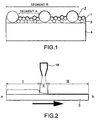
- the surface of the hydrophilic layer (b) has a relatively smooth portion and a portion which has risen as compared with the smooth portion, that is, a profile peak portion.
- a segment is set in the smooth portion, that is, only a portion not containing the profile peaks (segment A in Fig. 1)
- Rz ten-point mean roughness
- Sm mean distance between concaves and convexes
- Rz ten-point mean roughness
- Sm mean distance between concaves and convexes
- the surface of the hydrophilic material according to the first aspect of the present invention exhibits a high level of hydrophilicity such that a water layer is rapidly formed under wet conditions.
- a mirror as the hydrophilic material according to the present invention is provided in a bathroom, upon the adherence of steam or water spray on the surface of the mirror, the hydrophilic layer as the outermost surface continues to hold the adhered water as a water layer. In this state, the water layer on the hydrophilic layer can remain held even in the case where the surface temperature is the dew-point temperature or below, so far as water vapor comes into contact with the surface of the hydrophilic layer, or so far as water droplets are adhered by the adherence of water spray.
- Fogging of a mirror or a glass refers to a phenomenon such that the adhered water becomes fine water droplets which are adhered onto the surface and thus scatter light.
- the adhered water is brought to a homogeneous water layer rather than water droplets. Therefore, this "fogging" phenomenon does not take place.
- the adhered water is sometimes brought to relatively large water droplets rather than fine water droplets. These large water droplets distort an image reflected in the mirror. Further, in the transparent glass, these large water droplets distort an image seen through the transparent glass.
- the hydrophilic material according to the present invention does not form such relatively large water droplets and thus does not cause distortion of the image, that is, exhibits an excellent antifogging property.
- water has been excessively adhered, water flows down. Since, however, the hydrophilic layer on the substrate continues to hold the water layer on a certain level, the antifogging property can be maintained.
- the hydrophilic material according to the present invention has also an excellent antifouling property.
- the hydrophilic material according to the present invention can prevent the deposition of metal soap or rinse component in an bathroom environment, and can prevent the deposition of urban soot and dust in the open in the case of building materials such as outer walls.
- the hydrophilic metal oxide particles comprise first hydrophilic metal oxide particles having a particle diameter distribution with the mode of particle diameter being 3 to 40 nm (preferably 10 to 30 nm) and second hydrophilic metal oxide particles having a particle diameter distribution with the mode of particle diameter being 40 to 300 nm (preferably 40 to 100 nm). That is, hydrophilic metal oxide particles having the above two types of particle diameter ranges are used in combination. By virtue of this, the above-described Rz and Sm requirements can be relatively easily satisfied.
- Fig. 1 is a schematic cross-sectional view of one embodiment of the hydrophilic material according to the first aspect of the present invention.
- the Rz and Sm requirements are satisfied by first hydrophilic metal oxide particles 1, second hydrophilic metal oxide particles 2, and a hydrophilic inorganic amorphous material 3.
- the surface of the hydrophilic material according to the first aspect of the present invention is such that large and small concaves and convexes are provided on the surface of a substrate 4. These large and small concaves and convexes are considered to increase the surface area of the hydrophilic layer and consequently to maximize the hydrophilicity of the surface of the hydrophilic layer.
- a water layer is easily formed on the surface of the hydrophilic material and, at the same time, a satisfactory amount of water layer can be evenly held on the surface of the hydrophilic material. Further, it is considered that the adhered water droplets are attracted toward tall portions in the concaves and convexes to accelerate the spread of the water layer.
- Regulating the zeta potential to a range close to zero can effectively prevent the deposition of charged soil.
- the regulation of the zeta potential can suppress the deposition of cationic surfactants contained as a main component of a rinse and anionic surfactants contained in a shampoo caused within a bathroom, can prevent a lowering in hydrophilicity or the development of water repellency, and thus can realize the retention of the antifogging property for a longer period of time.
- the zeta potential is further preferably brought to -25 to 0 mV. In this case, the deposition of negatively charged soil, such as silica or clayey inorganic materials, can be effectively prevented. This is advantageous when the hydrophilic material according to the present invention is utilized in the open exposed to dust in the air and exhaust gas of automobiles.
- the surface roughness in an area of any 5 ⁇ m square of the surface in the hydrophilic layer is 5 to 30 nm.
- the antifogging effect and a high level of water layer holding capacity attained by the improved wettability and the transparency and the endurance properties can be further improved.
- the static contact angle of the hydrophilic layer with water is not more than 35 degrees. This permits the water layer to be efficiently formed upon the deposition of water droplets, and, thus, the antifogging property can be improved. Bringing the static contact angle of the hydrophilic layer with water to not more than 20 degrees is more preferred because the water layer can be rapidly formed. In the case of stains or soils having relatively low polarity, such as greasy stains and soils generated, for example, from exhaust gas, a contact angle of not more than 35 degrees suffices for easily removing these stains or soils, for example, by rainwater. The contact angle is further preferably not more than 20 degrees.
- the hydrophilic metal oxide particles comprise both hydrophilic metal oxide particles having positive charges and hydrophilic metal oxide particles having negative charges.
- Hydrophilic metal oxide particles having positive charges include: those having a positive zeta potential at pH 7, for example, MgO, La 2 O 3 , ZnO, ⁇ -Fe 2 O 3 , Y 2 O 3 , ⁇ -Al 2 O 3 , and ⁇ -Al 2 O 3 ; and those having a negative zeta potential at pH 7, for example, Cr 2 O 3 , CeO 2 , ZrO 2 , ⁇ -Fe 2 O 3 , FeO, Fe 3 O 4 , TiO 2 , SnO 2 , MnO 2 , SiO 2 , and Sb 2 O 5 .
- MgO, Al 2 O 3 , ZnO, ZrO 2 , TiO 2 , Fe 2 O 3 , and SnO 2 are preferred because they have a high level of hydrophilicity.
- composite oxides of SiO 2 , Al 2 O 3 , TiO 2 , ZrO 2 , MgO, SnO 2 , ZnO, Bi 2 O 3 , CdO, PbO and the like are mainly strongly acidic, and are effective as materials having a positive zeta potential.
- a coating composition suitable for the formation of a hydrophilic layer according to the first aspect of the present invention comprises at least a solvent and first hydrophilic metal oxide particles and second hydrophilic metal oxide particles as solutes.
- Examples of preferred solvents include water and alcohols. Water is particularly preferred from the viewpoints of hydrophilicity and safety.
- the coating composition may further contain a precursor of the hydrophilic inorganic amorphous material as an additional solute.
- the precursor of the hydrophilic inorganic amorphous material is a material which, upon the removal of the solvent and optional heat treatment, is converted to the above-described hydrophilic inorganic amorphous material (i), and a preferred example of the precursor is at least one member selected from the group consisting of alkali silicates, alkali borosilicates, alkali zirconates, and metal phosphates, such as alkali phosphates.
- alkali silicates are more preferred from the viewpoints of layer forming property and hydrophilicity.
- the weight ratio of the amount of SiO 2 in the alkali silicate to the hydrophilic metal oxide particles is in the range of 10 : 1 to 1 : 4
- the weight ratio of the amount of the first hydrophilic metal oxide particles to the amount of the second hydrophilic metal oxide particles is in the range of 40 : 1 to 1 : 4.
- the hydrophilic layer may also be formed in two stages wherein upper and lower layers are formed in these respective stages.
- the hydrophilic layer may be such that the composition of the final layer contains the first and second hydrophilic metal oxide particles and the alkali silicate.
- the coating composition to be coated as the lower layer may not contain the precursor of the hydrophilic inorganic amorphous material.
- the weight ratio of the amount of SiO 2 in the alkali silicate to the hydrophilic metal oxide particles is in the range of 10 : 1 to 1 : 4
- the weight ratio of the amount of the first hydrophilic metal oxide particles to the amount of the second hydrophilic metal oxide particles is in the range of 40 : 1 to 1 : 4
- the weight ratio of the amount of SiO 2 in the alkali silicate to the hydrophilic metal oxide particles is in the range of 20 : 1 to 1 : 2.
- hydrophilic metal oxide particles having positive charges may be incorporated as the first and/or second hydrophilic metal oxide particles.
- at least one member selected from the group consisting of boric acid, boric acid compounds, phosphoric acid, phosphoric acid compounds, and precursors of materials, which, upon heat treatment, are converted to ZrO 2 may be further incorporated as the solute.
- the hydrophilic material according to the first aspect of the present invention may be produced through the step of coating the above coating composition onto a substrate to form a hydrophilic layer.
- the hydrophilic material may be produced through the step of coating the above coating composition onto a substrate to form a first hydrophilic layer and the step of further coating a solution of an alkali silicate or the above coating composition onto the first hydrophilic layer to form a second hydrophilic layer.
- the method for coating the coating composition is not particularly limited, and examples thereof include spray coating, flow coating, spin coating, dip coating, and roll coating.
- spray coating flow coating
- spin coating dip coating
- roll coating the optimal mixture concentration varies depending upon coating methods, according to these coating methods, coating followed by drying can form a layer. Therefore, these coating methods are not considered to have an influence on the form of concaves and convexes in the hydrophilic layer so far as the ratio of the ingredients is not changed.
- the layer formed from the coating composition may be heat treated.
- the surface temperature of the layer is more preferably brought to 80 to 500°C. Bringing the surface temperature of the layer to this temperature range can satisfy water resistance requirement, while preventing a lowering in hydrophilicity caused by the stabilization of the structure in the surface of the inorganic material.
- the hydrophilic layer (b) comprises at least a first hydrophilic layer consisting essentially of a hydrophilic inorganic amorphous material and hydrophilic metal oxide particles and a second hydrophilic layer provided as the outermost layer on the first hydrophilic layer, said second hydrophilic layer consisting essentially of a hydrophilic inorganic amorphous material.
- concaves and convexes which are optimal for ensuring the antifogging property, are first formed by hydrophilic metal oxide particles contained in the first hydrophilic layer on the surface of the hydrophilic material.
- the second hydrophilic layer not containing hydrophilic metal oxide particles is formed as the outermost layer. This permits the highest level of hydrophilicity possessed by the hydrophilic inorganic amorphous material to be exhibited. That is, it is considered that excellent antifogging property and antifouling property can be realized by regulating the form of concaves and convexes in the hydrophilic layer by the first hydrophilic layer and enhancing the hydrophilicity by the second hydrophilic layer.
- water is adhered onto the second hydrophilic layer, and this layer is vertically held to remove excess water to bring the weight of the water layer adhered onto the hydrophilic layer to 0.25 to 0.50 g per 10 cm 2 , more preferably 0.25 to 0.35 g per 10 cm 2 .
- Bringing the weight of the water layer to this range can form a homogenized, even, and satisfactory water layer on the surface of the hydrophilic layer, and, thus, an excellent antifogging property can be exhibited.
- high hardness can be realized, and, thus, excellent endurance properties can also be provided.
- This weight of water layer can be realized by properly combining the first hydrophilic layer with the second hydrophilic layer.
- the weight of the water layer is specifically measured as follows. At the outset, an environment of temperature 15 to 25°C (room temperature) and relative humidity 30 to 80% is provided.
- the hydrophilic material is previously stabilized in this environment for one hr or longer, and the mass (X g) of the stabilized hydrophilic material is measured with a balance. After the measurement, the material is disposed so that the hydrophilic surface is rendered substantially vertical. Only the hydrophilic layer is wetted with water, of which the temperature has been made substantially equal to room temperature (15 to 25 degrees), to confirm that the whole hydrophilic layer has been wetted to form a water layer.
- the ten-point mean roughness (Rz) of 5 ⁇ m square at any position of the surface of the hydrophilic layer is 20 to 300 nm, more preferably 30 to 200 nm, still more preferably 40 to 150 nm.
- Rz ten-point mean roughness
- This surface state in terms of Rz may be realized by any method without particular limitation. For example, dispersion of hydrophilic metal oxide particles in the first hydrophilic layer can realize the above surface state.
- the zeta potential at pH 7 of the surface of the hydrophilic layer is -40 to 40 mV, more preferably-30 to 30 mV.
- Regulating the zeta potential to a range close to zero in this way can effectively prevent the deposition of charged soil.
- the regulation of the zeta potential can suppress the deposition of cationic surfactants contained as a main component of a rinse and anionic surfactants contained in a shampoo caused within a bathroom, can prevent a lowering in hydrophilicity or the development of water repellency, and thus can realize the retention of the antifogging property for a longer period of time.
- the zeta potential is further preferably brought to -25 to 0 mV. In this case, the deposition of negatively charged soil, such as silica or clayey inorganic materials, can be effectively prevented. This is advantageous when the hydrophilic material according to the present invention is utilized in the open exposed to dust in the air and exhaust gas of automobiles.
- the static contact angle of the hydrophilic layer with water is not more than 35 degrees. This permits the water layer to be efficiently formed upon the deposition of water droplets, and, thus, the antifogging property can be improved. Bringing the static contact angle of the hydrophilic layer with water to not more than 20 degrees is more preferred because the water layer can be rapidly formed. In the case of stains or soils having relatively low polarity, such as greasy stains and soils generated, for example, from exhaust gas, a contact angle of not more than 35 degrees suffices for easily removing these stains or soils, for example, by rainwater. The contact angle is further preferably not more than 20 degrees.
- the hydrophilic metal oxide particles comprise both hydrophilic metal oxide particles having positive charges and hydrophilic metal oxide particles having negative charges.
- Hydrophilic metal oxide particles having positive charges include: those having a positive zeta potential at pH 7, for example, MgO, La 2 O 3 , ZnO, ⁇ -Fe 2 O 3 , Y 2 O 3 , ⁇ -Al 2 O 3 , and ⁇ -Al 2 O 3 ; and those having a negative zeta potential at pH 7, for example, Cr 2 O 3 , CeO 2 , ZrO 2 , ⁇ -Fe 2 O 3 , FeO, Fe 3 O 4 , TiO 2 , SnO 2 , MnO 2 , SiO 2 , and Sb 2 O 5 .
- MgO, Al 2 O 3 , ZnO, ZrO 2 , TiO 2 , Fe 2 O 3 , and SnO 2 are preferred because they have a high level of hydrophilicity.
- composite oxides of SiO 2 , Al 2 O 3 , TiO 2 , ZrO 2 , MgO, SnO 2 , ZnO, Bi 2 O 3 , CdO, PbO and the like are mainly strongly acidic, and are effective as materials having a positive zeta potential.
- a set of the first coating composition for the formation of the first hydrophilic layer and the second coating composition for the formation of the second hydrophilic layer may be used as a coating composition suitable for the formation of the hydrophilic layer according to the second aspect of the present invention.
- the first coating composition consists essentially of a mixed solution composed of an alkali silicate and hydrophilic metal oxide particles, or a suspension of a metal oxide.
- the SiO 2 concentration (A) of the alkali silicate is 0.001 to 5% by weight
- the second coating composition consists essentially of an alkali silicate solution and does not contain any hydrophilic metal oxide particles.
- Water or alcohol is preferred as a solvent for the first and second coating compositions from the viewpoints of stability and workability.
- the solvent is not particularly limited to water or alcohol.
- various optional components which may be added to the hydrophilic layer, may be added to the first and/or second coating compositions.
- at least one member selected from the group consisting of boric acid, boric acid compounds, phosphoric acid, phosphoric acid compounds, and precursors of materials, which, upon heat treatment, are converted to ZrO 2 may be further incorporated as a solute.
- both hydrophilic metal oxide particles having positive charges and hydrophilic metal oxide particles having negative charges are incorporated as hydrophilic metal oxide particles.
- the hydrophilic material according to the second aspect of the present invention may be produced by a process comprising the steps of: coating the first coating composition onto a substrate to form a first hydrophilic layer; and further coating the second coating composition onto the surface of the first hydrophilic layer to form a second hydrophilic layer.
- the method for coating the coating composition is not particularly limited, and examples thereof include spray coating, flow coating, spin coating, dip coating, and roll coating.
- spray coating flow coating
- spin coating dip coating
- roll coating the optimal mixture concentration varies depending upon coating methods, according to these coating methods, coating followed by drying can form a layer. Therefore, these coating methods are not considered to have an influence on the form of concaves and convexes in the hydrophilic layer so far as the ratio of the ingredients is not changed.
- the coating of the first coating composition and/or the coating of the second coating composition may be heat treated.
- the surface temperature of the layer is more preferably brought to 80 to 500°C.
- the surface temperature of the layer is brought to this temperature range, the water resistance requirement can be satisfied, while preventing a lowering in hydrophilicity caused by the stabilization of the structure in the surface of the inorganic material.
- the layer forming apparatus comprises: coating means for coating hydrophilic coating composition onto a substrate; a coating thickness regulation means for regulating the thickness of the coating of the coating composition; and heating means for heating the coating composition as the coating after the regulation of the coating thickness, wherein the coating thickness regulation means sprays gas onto the substrate to regulate the coating thickness to a desired value.
- coating means provided separately from the coating thickness regulation means, and, further, coating thickness regulation means is provided downstream of the coating means.
- a layer can be evenly formed with a high efficiency onto substrates having a flat surface, as well as onto substrates having various surface shapes, such as curved surfaces and surfaces having irregularities.
- non-contact coating thickness regulation means wherein gas is sprayed against the substrate to regulate the coating thickness, the coating thickness can be regulated as desired without undergoing any influence of the surface shape.
- the layer forming apparatus can form layers having various properties
- the use of this layer forming apparatus as an apparatus for the formation of a hydrophilic layer (for example, an antifogging layer) is preferred.
- a hydrophilic layer for example, an antifogging layer
- the use of the apparatus according to the present invention can eliminate the above variation in the hydrophilic layer and permits the function inherent in the hydrophilic layer to be satisfactorily exhibited.
- alkali silicate layers are more preferred. The alkali silicate is likely to cause a clouded state, for example, particularly due to a very small variation in layer thickness.
- the apparatus according to the present invention can effectively solve the above problem.
- the substrate may be of various types. Preferably, however, the substrate is the same as that used in the hydrophilic materials according to the first and second aspects of the present invention.
- the coating means according to the present invention is used for coating the coating composition onto the substrate.
- the coating means may be of various types. Examples of preferred coating means include flow coating means and spray coating means. However, flow coating means is preferred because the inclusion of air can be minimized.
- a hydrophilic coating composition more preferably a coating composition as described above in connection with the first and second aspects of the present invention, is used as the coating composition.
- This can form a hydrophilic layer possessing excellent antifogging and antifouling properties.
- the coating thickness regulation means regulates and optimizes the coating thickness of the coating composition after coating, and is disposed on the downstream side in the direction of carriage of the coating means.
- the coating thickness regulation means is of non-contact type wherein gas is sprayed against the substrate to regulate the thickness of coating of the coating composition after the coating to a desired value. In this way, when the coating thickness is regulated in a non-contact manner using gas as a medium, a layer having even thickness can be easily formed without undergoing any influence of the form of the surface while preventing surface contamination and damage.
- the coating thickness regulation device is constructed so that a spout of a parallel slit is provided at a position such that the distance from the surface of the substrate being carried is identical, and gas is ejected through the spout.
- gas can be evenly ejected to evenly regulate the coating thickness.
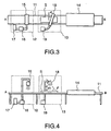
- Fig. 2 is a conceptual diagram illustrating the formation of a coating by means of the non-contact coating thickness regulation means.
- a substrate S advances from A toward B.
- zone I shows a state such that the coating composition has been coated onto the surface of the substrate.
- zone II in the drawing excessive coating composition is removed by a slit gas ejector 8 to regulate the coating thickness to a proper value.
- Zone III in the drawing shows a coating after the regulation of the coating thickness, and, in this case, the coating may be brought to a dried coating or a wet coating depending upon coating thickness regulation conditions.
- the coating thickness regulation means is constructed so as to have the function of drying the coating of the coating composition. According to this construction, contaminants are less likely to be included in the surface of the layer in the step of baking.
- the heating means according to the present invention heats the coating of the coating composition after the regulation of the coating thickness to fix the layer to the substrate, and is disposed on the downstream side in the direction of carriage of the coating thickness regulation means.
- Various heating methods may be adopted in the heating means according to the present invention, and are not particularly limited. Examples of preferred heating methods usable herein include infrared, near infrared, extreme infrared, and hot air heating methods.
- extreme infrared heating means is used as the heating means.
- heat can be efficiently applied to the surface and, thus, burning time necessary for hardening the layer can be shortened.
- adoption of a rapid heating method, wherein heat is concentrated onto only the surface is more preferred because the baking time can be further shortened contributing to improved productivity.
- the present invention is also suitable for use in the formation of a layer on the surface of a mirror with a protective resin layer being provided on the backside thereof.
- the heating means is preferably provided with means for cooling the backside of the substrate so that excessive heat is not applied to the protective resin layer.
- the coating means (a), the coating thickness regulation means (b), and the heating means (c) are preferably constructed so that a layer can be continuously formed through carrying means.
- carrying means include, but are not particularly limited to, belt conveyors and roller conveyors. Among them, roller conveyors are preferred from the viewpoint of the efficiency of recovery of excess coating composition, and mesh conveyors are preferred because the backside of the material can be easily cooled.
- a cleaning device for cleaning the surface of the hydrophilic layer is further provided downstream of the heating means.
- the provision of the cleaning device enables, for example, the removal of contaminants in the step of baking and the removal of unnecessary ingredients of the coating composition.
- means for cleaning with a detergent is provided separately from means for removing the detergent. This construction is preferred because the detergent is less likely to be left on the substrate with a layer formed thereon.
- the means for removing the detergent may be of contact type or non-contact type. The non-contact type, however, is preferred from the viewpoint of preventing the surface of the layer from being contaminated or damaged. Coating with the detergent may also be used in combination with cleaning by a physical method, for example, using a sponge or a brush.
- cleaning means for cleaning the surface of the substrate may be provided upstream of the coating means.
- the cleaning means preferably comprises: polishing agent supply means for supplying a polishing agent onto the surface of the substrate; surface polishing means for polishing the surface of the substrate with the supplied polishing agent; and polishing agent removing means for removing the polishing agent after the polishing.
- a cooling device for cooling the substrate is provided downstream of the heating device.
- the cooling rate can be properly set, and, thus, strength or other properties of substrates, such as reinforced glass, can be controlled, or it is possible to prevent damage to glass substrates which are broken upon rapid cooling.
- the position of the cooling device disposed is not particularly limited so far as the cooling device is disposed downstream of the heating means.
- the cooling device is disposed upstream of the cleaning device, for precooling before the treatment in the cleaning device.
- Figs. 3 and 4 are schematic diagrams of the layer forming apparatus according to the present invention, wherein Fig. 3 is a plan view and Fig. 4 a front view.
- the layer forming apparatus according to the present invention comprises coating means 12, coating thickness regulation means 13, and heating means 14 which are arranged in that order and are connected to one another through a carrier conveyor 11 which can carry a substrate.
- the carrier conveyor 11 is a slat conveyor (JIS B 0140), formed of a mesh metal, which carries a substrate S from the coating means 12 toward the heating means 14 (from A toward B in Figs. 3 and 4).
- the coating means 12, the coating thickness regulation means 13, and the heating means 14 are arranged in that order on the carrier conveyor 11.
- the coating means 12 coats a coating composition onto the substrate S, and comprises a coating nozzle 15, a pump 16, and a coating composition tank 17. As shown in Figs. 3 and 4, the coating means 12 is constructed so that a coating composition stored in the coating composition tank 17 supplied through a pump 16 into a coating nozzle 15 through which the coating composition is coated onto the substrate S.
- the coating means 12 can coat the coating composition onto the substrate in its whole coating face.
- the coating composition can be supplied into the coating nozzle by any method without particular limitation to the method shown in the drawing.
- Examples of other methods include: a force supply method wherein pressure is applied through a compressor to the coating composition tank to supply the coating composition; and a self-weight method wherein the coating composition is pumped into the coating composition tank disposed at a position above the coating nozzle and is spontaneously dropped on the coating nozzle.
- the coating thickness regulation means is disposed downstream of the coating means, the coating means is not particularly limited so far as the coating composition can be coated onto the substrate in its whole coating face.
- suitable coating means include curtain flow utilizing a slit nozzle, spray coating, roll coater coating, and brush coating. In particular, curtain flow is more preferred because the air is less likely to cause the inclusion of air in the coating.
- Figs. 5 and 6 are schematic views showing one embodiment of the coating nozzle 15, wherein A is a cross-sectional view and B a front view.
- the coating nozzle 15 comprises a container 20 for storing the coating composition, a coating composition supply port 21 provided at the upper part of the container, an overflow 22 provided at the upper part of the side face of the container, openings 23 provided as holes at the bottom of the container, and needle materials 24 which are provided so as to be insertable into the openings and function to regulate the amount of the coating composition discharged.
- the coating composition is supplied to the container 20 through the coating composition supply port 21, and excessive coating composition is discharged through the overflow 22.
- the coating composition reservoired in the container is passed through the openings 23 provided at the bottom of the container and is dropped on the substrate S.
- the amount of the coating composition discharged can be closely controlled by inserting the needle materials 24 into the respective openings 23 and vertically moving the needle materials 24. More specifically, the coverage is controlled by the diameter d2 of the openings 23, the diameter d4 of the needle material 24 inserted into the hole, and the spacing d3 of the holes 23. This method does not require any complicate equipment. Further, the use of the needle material 24 can prevent foaming of the coating composition on the substrate and, in addition, can minimize the amount of the coating composition dropped.
- the amount of the coating composition dropped onto the substrate is preferably 30 to 5000 cm 3 , more preferably 50 to 1000 cm 3 , in terms of coverage per m 2 of the coating face. When the coverage falls within this range, uneven coating is less likely to occur and, in addition, this is also advantageous from the viewpoint of cost.
- the coating thickness regulation means 13 comprises a slit gas ejector 18 and a blower 19, and is disposed downstream of the coating means 12 through the carrier conveyor 11.
- the slit gas ejector 18 is a device for spraying gas on the substrate S in its coating composition coating face, and is preferably in the form of a parallel slit, which is located at a position such that the distance from the surface of the substrate being carried is identical, from the viewpoint of evenly ejecting gas onto the substrate to evenly regulate the coating thickness.
- the slit is preferably prepared so as to conform to the shape of the substrate. For example, when the substrate is in a flat plate form, the slit is preferably in a parallel linear form.
- the substrate when the substrate is in a cylindrical form, a method may be used wherein donut-shaped slits are disposed around the cylindrical substrate and the substrate is passed through the cylindrically arranged slits.
- the blower 19 supplies gas into the gas ejector 18.
- a filter for removing foreign matter is preferably used to suppress the deposition of contaminants onto the coating face.
- the pressure of air supplied by the blower is preferably 0.1 to 20 kPa, more preferably 0.4 to 2 kPa.
- the angle of the slit gas ejector 18 to the carrier conveyor 11 is preferably -60 to 60 degrees. This facilitates the separation of excess coating composition removed from the substrate. Further, the angle of the ejection of gas to the substrate (angle ⁇ in Fig. 4) is preferably 40 to 130 degrees. When the angle ⁇ is in this range, the gas can strongly impact against the coating composition as the coating, and, thus, the coating thickness can be easily regulated. In addition, there is no fear that the gas after the completion of the coating thickness comes into contact with the coating composition as the coating before the regulation of the thickness and consequently causes waves and renders the coating uneven. Further, an angle ⁇ of 40 to 90 degrees is preferred from the viewpoint of regulating the coating thickness with good reproducibility.
- the spacing d1 between the slit gas ejector 18 and the substrate S is preferably 1 mm to 50 mm.
- the spacing d1 in the range of 1 mm to 50 mm can eliminate the possibility of the contact of the coating composition with the slit gas ejector and, in addition, permits the gas to strongly impact against the coating composition to satisfactorily regulate the coating thickness. Further, this can more effectively prevent the inclusion of foreign matter or contaminants, present around the substrate, in the coating.
- Figs. 7 and 8 are schematic cross-sectional view of the heating means 14.
- the heating means 14 shown in Fig. 7 is an embodiment wherein means for cooling the backside of the substrate is used.
- This heating means comprises a heating element 25, a cooling nozzle 26, and an exhaust nozzle 27, and is disposed downstream of the coating thickness regulation means 13 through the carrier conveyor 11.
- the heating element 25 is provided above the carrier conveyor 11 so as to be parallel to the carrier face.
- An extreme infrared heater is preferably used as the heating element 25.
- the means for cooling the backside of the substrate is inserted below of the heating means 14, particularly below the carrier conveyor 11.
- the means for cooling the backside of the substrate comprises a cooling nozzle 26 for applying cooling air to the backside of the substrate S and an exhaust nozzle 27 for discharging the air from the cooling nozzle.
- cooling air is applied to the carrying line by means of a blower or the like.
- the cooling nozzle 26 may be constructed so that cooling water is allowed to flow.
- the provision of the backside cooling means permits the temperature of the backside of the substrate on the carrying line to be always kept below the temperature of the top surface of the substrate. Therefore, this is particularly effective in the case of a substrate with a protective resin layer being provided on the backside thereof, such as a mirror.
- a construction may also be adopted wherein means for cooling the substrate after the formation of the layer is provided downstream of the heating means.
- cooling means include: air cooling means for air cooling the substrate while allowing the substrate to contact with fresh air; blowing means; and furnace cooling means. Further, as shown in Fig. 8, it is a matter of course that the heating means 14 may not have any backside cooling means.
- Figs. 9 to 12 are cross-sectional views showing embodiments of the form of the substrate surface on which a layer can be formed by the layer forming apparatus according to the present invention. Even in the case of complicate forms of substrate surface other than those shown in Figs. 9 to 12, a layer can be formed by properly setting the speed of the carrier conveyor and the coating thickness regulation means.
- Examples A1 to A4 and Comparative Examples A1 and A2 are provided for evaluating the hydrophilic material according to the first aspect of the present invention. That is, specimens prepared in Examples A1 to A4 fall within the scope of the first aspect of the present invention. Hydrophilic materials in these examples were evaluated by the following methods.
- a segment was set so as not to pass through metal oxide particles having a large particle diameter exposed to the surface to calculate Rz and Sm which were designated as Rz1 and Sm1, respectively. Further, a segment was set so as to pass through metal oxide particles having a large particle diameter to calculate Rz and Sm which were designated as Rz2 and Sm2, respectively.
- Test A4 Evaluation of antifouling property for bathroom (part A)
- a specimen was provided, and water was showered on the specimen.
- the contaminated water A and the contaminated water B each were deposited in an amount of about 0.5 g per 100 mm x 100 mm.
- This specimen was dried for 15 min in a drier set at 40°C. This procedure was repeated seven times, and, thereafter, the specimen was cleaned with a sponge for a bath with the aid of a neutral detergent for a bath. The above procedure completed one cycle. For each cycle, the hydrophilicity was evaluated in the same manner as described above in connection with the test A3.
- Test A5 Evaluation of antifouling property for bathroom (part B)
- the antifouling property for a bathroom was evaluated in the same manner as used in the test A4, except that, after the deposition of contaminated water and before drying in a drier, the specimen was showered with running water.
- Test A6 Endurance to detergent for mould killing
- the specimen was immersed in a commercially available detergent for mound killing (Kabi Killer, manufactured by Johnson) for 24 hr. After the immersion, the specimen was inspected for the state of the layer, and, in addition, was evaluated for the hydrophilicity in the same manner as used in the test A3.
- a commercially available detergent for mound killing Karl Killer, manufactured by Johnson
- the contamination accelerating liquid used was a pseudo-stain which had been prepared as a material alternative to a contaminant in an urban area. More specifically, the contamination accelerating liquid was a dispersion of 0.05 g of carbon black, 0.05 g of silica, 0.225 g of fired Kanto loam soil, and 0.675 g of yellow soil in 1000 cm 3 of water.
- a commercially available glass mirror having a size of 10 cm square was provided as a substrate 4. This substrate was cleaned with cerium oxide powder.
- Lithium silicate (Lithium Silicate 35, manufactured by Nissan Chemical Industries Ltd.) was provided as a hydrophilic inorganic amorphous material, silica particles (Snowtex 50, particle diameter 20 to 30 nm, manufactured by Nissan Chemical Industry Ltd.) were provided as first hydrophilic metal oxide particles, and silica particles (Snowtex ZL, particle diameter 70 to 100 nm, manufactured by Nissan Chemical Industry Ltd.) were provided as second hydrophilic metal oxide particles.
- a coating composition A containing 0.75% by weight, in terms of SiO 2 concentration, of the hydrophilic inorganic amorphous material, 0.75% by weight, in terms of SiO 2 concentration, of the first hydrophilic metal oxide particles, and 0.75% by weight, in terms of SiO 2 concentration, of the second hydrophilic metal oxide particles.
- an alkali silicate (SLN 73 (components: SiO 2 , Na 2 O, Li 2 O, and B 2 O 3 ), manufactured by Nippon Chemical Industrial Co., Ltd.) was provided as a hydrophilic inorganic amorphous material, and silica particles (Snowtex 20, particle diameter 10 to 20 nm, manufactured by Nissan Chemical Industry Ltd.) were provided as first hydrophilic metal oxide particles.
- SSN 73 components: SiO 2 , Na 2 O, Li 2 O, and B 2 O 3
- silica particles Snowtex 20, particle diameter 10 to 20 nm, manufactured by Nissan Chemical Industry Ltd.
- the coating composition A was spin coated onto the surface of the substrate after the cleaning, and the coated substrate was then dried.
- the coating composition B was then spin coated onto the coating of the coating composition A, followed by drying.
- the dried, coated substrate was then heat treated at 150°C for 10 min. Thus, a specimen was prepared.
- the specimen was subjected to the tests A1 to A6.
- the results were as follows.
- a commercially available stainless steel reflecting mirror as a substrate was cleaned with a polishing agent.
- Lithium silicate (Lithium Silicate 75, manufactured by Nissan Chemical Industries Ltd.) was provided as a hydrophilic inorganic amorphous material, alumina particles (Alumina Sol 520, particle diameter 10 to 20 nm, manufactured by Nissan Chemical Industry Ltd.) were provided as first hydrophilic metal oxide particles, and zirconia particles (Zirconia Sol NZS-30B, particle diameter 70 nm, manufactured by Nissan Chemical Industry Ltd.) were provided as second hydrophilic metal oxide particles. These ingredients were dispersed in water to prepare a mixed solution containing 0.75% by weight of SiO 2 , 0.5% by weight of Al 2 O 3 , and 0.5% by weight of ZrO 2 . A minor amount of a dilution of aluminum phosphate (1% by weight on a solid basis) was added to the mixed solution to prepare a coating composition C.
- alumina particles Allumina Sol 520, particle diameter 10 to 20 nm, manufactured by Nissan Chemical Industry Ltd.
- zirconia particles Zirconia Sol N
- the coating composition C was flow coated onto the surface of the substrate after the cleaning, and the coated substrate was then dried.
- the coated substrate was then heat treated at 250°C for 5 min. Thus, a specimen was prepared.
- the specimen was subjected to the tests A1 to A5.
- the results were as follows.
- a transparent acrylic plate having a size of 10 cm square was provided as a substrate. This substrate was degreased and cleaned.
- Silica particles (Snowtex 50, particle diameter 20 to 30 nm, manufactured by Nissan Chemical Industry Ltd.) were provided as first hydrophilic metal oxide particles, and silica particles (Snowtex XL, particle diameter 40 to 60 nm, manufactured by Nissan Chemical Industry Ltd.) were provided as second hydrophilic metal oxide particles. These ingredients were dispersed in water to prepare a coating composition D containing 0.75% by weight, in terms of SiO 2 concentration, of the first hydrophilic metal oxide particles and 0.75% by weight, in terms of SiO 2 concentration, of the second hydrophilic metal oxide particles.
- lithium silicate Lithium Silicate 35, manufactured by Nippon Chemical Industrial Co., Ltd.
- This ingredient was dispersed in water to prepare a coating composition E having an SiO 2 content of 1.25% by weight.
- the coating composition D was spray coated onto the surface of the substrate after the cleaning, and the coated substrate was then dried.
- the coating composition E was then spin coated onto the coating of the coating composition D.
- the coated substrate was then dried. Thus, a specimen was prepared.
- the specimen was subjected to the tests A1 to A5.
- the results were as follows.
- Two glazed porcelain white tiles (AB06E11, manufactured by TOTO, LTD.) were provided as substrates. Both the substrates were cleaned with a surfactant and were then air dried. The these two tiles were designated as tile A and tile B, respectively.
- Lithium silicate (Lithium Silicate 35, manufactured by Nissan Chemical Industry Ltd.) was provided as a hydrophilic inorganic amorphous material, silica particles (Snowtex 50, particle diameter 20 to 30 nm, manufactured by Nissan Chemical Industry Ltd.) and titanium oxide particles (A-6, particle diameter 10 nm, manufactured by Taki Chemical Co., Ltd.) were provided as first hydrophilic metal oxide particles 2, and silica particles (Snowtex ZL, particle diameter 70 to 100 nm, manufactured by Nissan Chemical Industry Ltd.) were provided as second hydrophilic metal oxide particles.
- a coating composition F containing 0.75% by weight, in terms of SiO 2 concentration, of the hydrophilic inorganic amorphous material, 0.2% by weight of the first hydrophilic metal oxide particles, 0.25% by weight, in terms of SiO 2 concentration, of the second hydrophilic metal oxide particles, and 0.3% by weight of TiO 2 .
- the coating composition F was spray coated onto the tile A only, and the coated tile was dried. Thereafter, the dried, coated tile was heat treated at 350°C for 5 min. Thus, a specimen was prepared.
- the tests A1 and A2 were carried out. Further, for the treated tile A (specimen) and the tile B, the test A7 was carried out. The results were as follows.
- a commercially available glass mirror having a size of 10 cm square was provided as a substrate.
- the substrate was cleaned with a neutral detergent and was then air dried. This substrate as such was used as a specimen.
- a commercially available plate glass having a size of 10 cm square was provided as a substrate. This substrate was cleaned with cerium oxide powder.
- Lithium silicate Lithium Silicate 35, manufactured by Nissan Chemical Industries Ltd.
- SiO 2 Lithium silicate 35, manufactured by Nissan Chemical Industries Ltd.
- the coating composition G was roll coated onto the surface of the substrate after the cleaning.
- the coated substrate was heat treated at 600°C for one min. Thus, a specimen was prepared.
- Examples B1 and B2 and Comparative Examples B1 and B2 are provided for evaluating the hydrophilic material according to the second aspect of the present invention. That is, specimens prepared in Examples B1 and B2 fall within the scope of the second aspect of the present invention. Hydrophilic materials in these examples were evaluated by the following methods.
- Test B1 Retention of water as water layer
- the specimen was held and stabilized in an environment set at room temperature (15 to 25°C) and a relative humidity of 30 to 80% for one hr or longer.
- the weight of the stabilized specimen was measured with an electronic force balance.
- this specimen was disposed so that the hydrophilic surface was substantially vertical. Thereafter, only the hydrophilic surface was wetted with water of which the temperature had been made substantially equal to room temperature (15 to 25°C). 15 sec after the wetting of the surface, water collected at the bottom was removed.
- the weight of the specimen, from which excess water had been removed, was measured with an electronic force balance.
- the degree of a change in weight of the specimen after the deposition of water from the weight of the specimen before the deposition of water was calculated to determine the weight of a water layer deposited on the specimen.
- the specimen was allowed to stand in a room of an environment of 20°C and 45%RH for one week or longer.
- the contact angle of the specimen with water was then measured with a contact angle goniometer (Model CA-X150, manufactured by Kyowa Interface Science Co., Ltd.).
- a pencil with a density symbol specified in JIS S 6006 was held at an angle of 45 degrees to the coating face, and the pencil was slid at a speed of about 3 mm per sec forward from the foreground with the strongest possible force such that the lead was not broken. At that time, the layer was inspected for damage. The highest pencil hardness, which did not damage the layer, was regarded as the pencil hardness of the specimen.
- the contamination accelerating liquid used was a pseudo-stain which had been prepared as a material alternative to a contaminant in an urban area. More specifically, the contamination accelerating liquid was a dispersion of 0.05 g of carbon black, 0.05 g of silica, 0.225 g of fired Kanto loam soil, and 0.675 g of yellow soil in 1000 cm 3 of water.
- a commercially available glass mirror having a size of 10 cm square was provided as a substrate. This substrate was cleaned with cerium oxide powder.
- Lithium silicate Lithium Silicate 35, manufactured by Nissan Chemical Industries Ltd.
- silica particles Silica particles
- These ingredients were dispersed in water to prepare a coating composition H containing 0.5% by weight, in terms of SiO 2 concentration, of lithium silicate and 0.5% by weight, in terms of SiO 2 concentration, of silica particles.
- an alkali silicate (SLN 73 (components: SiO 2 , Na 2 O, Li 2 O, and B 2 O 3 ), manufactured by Nippon Chemical Industrial Co., Ltd.) was diluted with water to prepare a coating composition I having an SiO 2 content of 2% by weight.
- the coating composition H was dip coated onto the surface of the substrate after the cleaning.
- the coating composition I was then dip coated onto the coating of the coating composition H.
- the coated substrate was then heat treated at 150°C for 10 min. Thus, a specimen was prepared.
- the specimen was subjected to the tests B1 to B5.
- the results were as follows.
- Two glazed porcelain white tiles (AB06E11, manufactured by TOTO, LTD.) were provided as substrates. Both the substrates were cleaned with a surfactant and were then air dried. The these two tiles were designated as tile C and tile D, respectively.
- Coating composition H and coating composition I were prepared in the same manner as in Example B1.
- the coating composition H was spray coated onto the tile C only. Thereafter, the coating composition I was sprayed on the coating of the coating composition H.
- the coated tile was heat treated at 150°C for, 10 min. Thus, a specimen was prepared.
- the specimen was subjected to the tests B1 to B4 and B6.
- the results were as follows.
- a commercially available glass mirror having a size of 10 cm square was provided as a substrate.
- the substrate was cleaned with a neutral detergent and was then air dried. This substrate as such was used as a specimen.
- a commercially available glass plate having a size of 10 cm square was provided as a substrate. This substrate was cleaned with cerium oxide powder.
- a coating composition G was prepared in the same manner as in Comparative Example A2.
- the coating composition G was roll coated onto the surface of the substrate after the cleaning.
- the coated substrate was heat treated at 600°C for 10 min. Thus, a specimen was prepared.
- Example C1 and Comparative Examples C1 and C2 are provided for evaluating the hydrophilic material according to the first aspect of the present invention. That is, specimens prepared in Example C1 fall within the scope of the first aspect of the present invention. Hydrophilic materials in these examples were evaluated by the following methods.
- the specimen was first immersed in warm water of 60°C for 8 hr. Thereafter, the specimen was washed with distilled water.
- the specimen was stored at room temperature for 10 days or longer.
- the contact angle of the specimen with water was then measured with a contact angle goniometer (Model CA-X150, manufactured by Kyowa Interface Science Co., Ltd.).
- Test C5 Antifouling property for bathroom
- a specimen having a size of 100 mm x 200 mm was brought to room temperature and was immersed in a 0.5% soap solution, and the surface of the specimen was then showered. Further, this specimen was immersed in a 0.5% rinse solution, and the surface of the specimen was showered. The specimen was then allowed to stand in a drier set at 50°C for 48 hr. Thereafter, the specimen was cleaned with a neutral detergent for bathing by means of a sponge. The treated specimen was then evaluated for hydrophilicity in the same manner as used in the test C4. This series of steps were repeated until the evaluation of the hydrophilicity became C, and the antifouling property was evaluated based on the number of times.
- a commercially available glass mirror was provided as a substrate. This substrate was polished with cerium oxide powder, and was then satisfactorily washed with running water.
- An alkali silicate (SLN 73 (components: SiO 2 , Na 2 O, Li 2 O, and B 2 O 3 ), manufactured by Nippon Chemical Industrial Co., Ltd.) was provided as a hydrophilic inorganic amorphous material, silica particles (Snowtex 50, particle diameter 20 to 30 nm, manufactured by Nippon Chemical Industrial Co., Ltd.) were provided as first hydrophilic metal oxide particles, and silica particles (Snowtex ZL, particle diameter 70 to 100 nm, manufactured by Nippon Chemical Industrial Co., Ltd.) and silica particles (Snowtex XL, particle diameter 40 to 60 nm, manufactured by Nippon Chemical Industrial Co., Ltd.) were provided as second hydrophilic metal oxide particles.
- composition J containing 0.4% by weight, in terms of SiO 2 concentration, of the alkali silicate, 0.2% by weight, in terms of SiO 2 concentration, of Snowtex ZL, 0.3% by weight, in terms of SiO 2 concentration, of Snowtex XL, and 0.2% by weight, in terms of SiO 2 concentration, of Snowtex 50.
- an alkali silicate (SLN 73 (components: SiO 2 , Na 2 O, Li 2 O, and B 2 O 3 ), manufactured by Nippon Chemical Industrial Co., Ltd.) was provided as a hydrophilic inorganic amorphous material, and silica particles coated with alumina (SILICADOL 20P, particle diameter 20 to 30 nm, manufactured by Nippon Chemical Industrial Co., Ltd.) were provided as hydrophilic metal oxide particles.
- SSN 73 components: SiO 2 , Na 2 O, Li 2 O, and B 2 O 3
- silica particles coated with alumina SILICADOL 20P, particle diameter 20 to 30 nm, manufactured by Nippon Chemical Industrial Co., Ltd.
- These ingredients were dispersed in water to prepare a coating composition K containing 0.25% by weight, in terms of SiO 2 content, of an alkali silicate and 0.5% by weight on a solid basis of silica particles coated with alumina.
- the coating composition J was spin coated onto the surface of the substrate after the cleaning.
- the coating composition K was then spin coated onto the coating of the coating composition J.
- the coated substrate was then heat treated at 150°C for 10 min. Thus, a specimen was prepared.
- the specimen was subjected to the tests C1 to C5.
- the results were as follows.
- a commercially available glass mirror was provided as a substrate.
- the substrate was cleaned with a neutral detergent. This substrate as such was used as a specimen.
- a commercially available glass mirror was provided as a substrate. This substrate was polished with cerium oxide powder, and was then satisfactorily washed with running water.
- An alkali silicate (SLN 73 (components: SiO 2 , Na 2 O, Li 2 O, and B 2 O 3 ), manufactured by Nippon Chemical Industrial Co., Ltd.) provided as a hydrophilic inorganic amorphous material was diluted to bring the SiO 2 content to 1% to prepare a coating composition L.
- the coating composition L was spin coated onto the surface of the substrate after the cleaning.
- the coated substrate was then heat treated at 150°C for 10 min. Thus, a specimen was prepared.
- the specimen was subjected to the tests C1 to C5.
- the results were as follows.
Landscapes
- Chemical & Material Sciences (AREA)
- Engineering & Computer Science (AREA)
- Materials Engineering (AREA)
- Organic Chemistry (AREA)
- Ceramic Engineering (AREA)
- Life Sciences & Earth Sciences (AREA)
- Structural Engineering (AREA)
- Inorganic Chemistry (AREA)
- General Chemical & Material Sciences (AREA)
- Geochemistry & Mineralogy (AREA)
- Chemical Kinetics & Catalysis (AREA)
- Wood Science & Technology (AREA)
- Dispersion Chemistry (AREA)
- Composite Materials (AREA)
- Laminated Bodies (AREA)
- Paints Or Removers (AREA)
- Application Of Or Painting With Fluid Materials (AREA)
- Surface Treatment Of Glass (AREA)
Abstract
Description
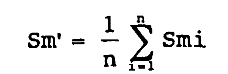
Claims (66)
- A hydrophilic material comprising at least a substrate and a hydrophilic layer provided as the outermost layer on the substrate,the hydrophilic layer compriseing at least hydrophilic metal oxide particles and a hydrophilic inorganic amorphous material,the hydrophilic layer having profile peaks on its surface,the hydrophilic layer having roughness properties such that, when a segment is set in only a portion not containing the profile peaks, the ten-point mean roughness (Rz) and the mean distance between concaves and convexes (Sm) obtained from a profile curve in the segment are 10 nm ≤ Rz ≤ 40 nm and 10 nm ≤ Sm ≤ 300 nm, respectively, while, when a segment is set so as to pass through the profile peaks, the ten-point mean roughness (Rz) and the mean distance between concaves and convexes (Sm) obtained from a profile curve in the segment are 40 nm ≤ Rz ≤ 200 nm and 300 nm ≤ Sm ≤ 1500 nm, respectively.
- The hydrophilic material according to claim 1, wherein the hydrophilic metal oxide particles comprise first hydrophilic metal oxide particles having a particle diameter distribution with the mode of particle diameter being not less than 3 nm and less than 40 nm and second hydrophilic metal oxide particles having a particle diameter distribution with the mode of particle diameter being not less than 40 nm and not more than 300 nm.
- The hydrophilic material according to claim 2, wherein the mode of particle diameter of the first hydrophilic metal oxide particles is 10 to 30 nm and the mode of particle diameter of the second hydrophilic metal oxide particles is 40 to 100 nm.
- The hydrophilic material according to any one of claims 1 to 3, wherein the hydrophilic metal oxide particles comprise at least one member selected from the group consisting of SiO2, Al2O3, ZrO2, TiO2, and SnO2.
- The hydrophilic material according to any one of claims 1 to 4, wherein the hydrophilic inorganic amorphous material comprises at least one member selected from the group consisting of alkali silicates, alkali borosilicates, alkali zirconates, and metal phosphates.
- The hydrophilic material according to any one of claims 1 to 5, wherein the zeta potential at pH 7 of the surface of the hydrophilic layer is -40 to 40 mV and the static contact angle of the layer with water is not more than 35 degrees.
- The hydrophilic material according to claim 6, wherein the zeta potential is -30 to 30 mV.
- The hydrophilic material according to claim 6, wherein the zeta potential is -25 to 0 mV.
- The hydrophilic material according to claim 6, wherein the static contact angle is not more than 20 degrees.
- The hydrophilic material according to any one of claims 1 to 9, wherein the hydrophilic metal oxide particles comprise both hydrophilic metal oxide particles having positive charges and hydrophilic metal oxide particles having negative charges.
- The hydrophilic material according to any one of claims 1 to 10, wherein the substrate is selected from the group consisting of inorganic materials, metal materials, organic materials, and composites of said materials.
- The hydrophilic material according to any one of claims 1 to 10, wherein the substrate is selected from the group consisting of tiles, sanitary wares, tablewares, glasses, mirrors, reflector plates, protective plates, protective films, ceramic wares, calcium silicate boards, cements, woods, resins, metals, and ceramics.
- The hydrophilic material according to any one of claims 1 to 10, wherein the substrate is selected from the group consisting of glasses, glass covers, mirrors, reflector plates, protective plates, films, and protective films.
- The hydrophilic material according to any one of claims 1 to 10, wherein the substrate is a material for bathrooms.
- The hydrophilic material according to any one of claims 1 to 10, wherein the substrate is a mirror for bathrooms.
- A coating composition for the production of the hydrophilic material according to any one of claims 1 to 15,said coating composition comprising a solvent and a solute,said solute comprising at least first hydrophilic metal oxide particles having a particle diameter distribution with the mode of particle diameter being 3 to 40 nm and second hydrophilic metal oxide particles having a particle diameter distribution with the mode of particle diameter being 40 to 300 nm.
- The coating composition according to claim 16, wherein the mode of particle diameter of the first hydrophilic metal oxide particles is 10 to 30 nm and the mode of particle diameter of the second hydrophilic metal oxide particles is 40 to 100 nm.
- The coating composition according to claim 16 or 17, which further comprises a precursor of the hydrophilic inorganic amorphous material.
- The coating composition according to claim 18, wherein the precursor of the hydrophilic inorganic amorphous material comprises at least one member selected from the group consisting of alkali silicates, alkali borosilicates, alkali zirconates, and metal phosphates.
- The coating composition according to claim 18 or 19, wherein the precursor of the hydrophilic inorganic amorphous material comprises an alkali silicate.
- The coating composition according to any one of claims 16 to 20, wherein the hydrophilic metal oxide particles comprises at least one member selected from the group consisting of SiO2, Al2O3, ZrO2, TiO2, and SnO2.
- The coating composition according to claim 20 or 21, wherein the weight ratio of the amount of SiO2 in the alkali silicate to the hydrophilic metal oxide particles is in the range of 10 : 1 to 1 : 4 and the weight ratio of the amount of the first hydrophilic metal oxide particles to the amount of the second hydrophilic metal oxide particles is in the range of 40 : 1 to 1 : 4.
- The coating composition according to claim 20 or 21, wherein the weight ratio of the amount of SiO2 in the alkali silicate to the hydrophilic metal oxide particles is in the range of 20 : 1 to 1 : 2.
- The coating composition according to any one of claims 16 to 23, wherein the first and/or second hydrophilic metal oxide particles comprise both hydrophilic metal oxide particles having positive charges and hydrophilic metal oxide particles having negative charges.
- The coating composition according to any one of claims 16 to 24, which further comprises at least one member selected from the group consisting of boric acid, boric acid compounds, phosphoric acid, phosphoric acid compounds, and precursors which, upon heat treatment, are converted to ZrO2.
- A process for producing the hydrophilic material according to any one of claims 1 to 15, comprising the step of:
coating the coating composition according to any one of claims 16 to 25 onto a substrate to form a hydrophilic layer. - A process for producing the hydrophilic material according to any one of claims 1 to 15, comprising the steps of:coating the coating composition according to any one of claims 16 to 25 onto a substrate to form a first hydrophilic layer; andfurther coating a solution of an alkali silicate or the coating composition according to any one of claims 16 to 25 onto the first hydrophilic coating to form a second hydrophilic layer.
- The process according to claim 26 or 27, which further comprises the step of heat treating the hydrophilic layer.
- The process according to claim 28, wherein the hydrophilic layer is heat treated by bringing the surface temperature of the hydrophilic layer to 80 to 500°C.
- A hydrophilic material comprising at least: a substrate; a first hydrophilic layer provided on the substrate, said first hydrophilic layer consisting essentially of a hydrophilic inorganic amorphous material and hydrophilic metal oxide particles; and a second hydrophilic layer provided as the outermost layer on the first hydrophilic layer, said second hydrophilic layer consisting essentially of a hydrophilic inorganic amorphous material.
- The hydrophilic material according to claim 30, wherein the hydrophilic inorganic amorphous material comprises at least one member selected from the group consisting of alkali silicates, alkali borosilicates, alkali zirconates, and metal phosphates.
- The hydrophilic material according to claim 30 or 31, wherein the hydrophilic inorganic amorphous material in the first and/or second hydrophilic layer is an alkali silicate.
- The hydrophilic material according to any one of claims 30 to 32, wherein the hydrophilic metal oxide particles comprises at least one member selected from the group consisting of SiO2, Al2O3, ZrO2, TiO2, and SnO2.
- The hydrophilic material according to any one of claims 30 to 33, wherein the mode of particle diameter of the hydrophilic metal oxide particles is 10 to 300 nm.
- The hydrophilic material according to any one of claims 30 to 34, wherein the ten-point mean roughness (Rz) as measured under an atomic force microscope in an area of 5 µm (one side) square in any position of the surface of the hydrophilic layer is 20 to 300 nm.
- The hydrophilic material according to claim 35, wherein the ten-point mean roughness (Rz) as measured under the atomic force microscope is 30 to 200 nm.
- The hydrophilic material according to claim 35, wherein the ten-point mean roughness (Rz) as measured under the atomic force microscope is 40 to 150 nm.
- The hydrophilic material according to any one of claims 30 to 37, wherein the zeta potential at pH 7 of the surface of the hydrophilic layer is -40 to 40 mV and the static contact angle of the layer with water is not more than 35 degrees.
- The hydrophilic material according to claim 38, wherein the zeta potential is -30 to 30 mV.
- The hydrophilic material according to claim 38, wherein the zeta potential is -25 to 0 mV.
- The hydrophilic material according to claim 38, wherein the static contact angle is not more than 20 degrees.
- The hydrophilic material according to any one of claims 30 to 41, wherein the hydrophilic metal oxide particles comprise both hydrophilic metal oxide particles having positive charges and hydrophilic metal oxide particles having negative charges.
- The hydrophilic material according to any one of claims 30 to 42, wherein the substrate is selected from the group consisting of inorganic materials, metal materials, organic materials, and composites of said materials.
- The hydrophilic material according to any one of claims 30 to 42, wherein the substrate is selected from the group consisting of tiles, sanitary wares, tablewares, glasses, mirrors, reflector plates, protective plates, protective films, ceramic wares, calcium silicate boards, cements, woods, resins, metals, and ceramics.
- The hydrophilic material according to any one of claims 30 to 42, wherein the substrate is selected from the group consisting of glasses, glass covers, mirrors, reflector plates, protective plates, and protective films.
- The hydrophilic material according to any one of claims 30 to 42, wherein the substrate is a material for bathrooms.
- The hydrophilic material according to any one of claims 30 to 42, wherein the substrate is a mirror for bathrooms.
- A set of coating compositions for the production of the hydrophilic material according to any one of claims 30 to 47, said coating composition set comprising:a first coating composition for the formation of the first hydrophilic layer, consisting essentially of a mixed solution composed of an alkali silicate and hydrophilic metal oxide particles, or consisting essentially of a suspension of a metal oxide; anda second coating composition for the formation of the second hydrophilic layer, consisting essentially of an alkali silicate solution.
- The set according to claim 48, wherein, in the first coating composition, the concentration (A) of SiO2 in the alkali silicate is 0.001 to 5% by weight and the concentration (B) of the hydrophilic metal oxide particles is A : B = 1 : 0.1 to 1 : 1000.
- The set according to claim 48 or 49, wherein the first and/or second coating compositions comprise at least one member selected from the group consisting of boric acid, boric acid compounds, phosphoric acid, phosphoric acid compounds, and precursors which, upon heat treatment, are converted to ZrO2.
- A process for producing the hydrophilic material according to any one of claims 30 to 47, comprising the steps of:coating the first coating composition according to any one of claims 48 to 50 onto a substrate to form a first hydrophilic layer; andfurther coating the second coating composition according to any one of claims 48 to 50 onto the surface of the first hydrophilic layer to form a second hydrophilic layer.
- The process according to claim 51, which further comprises the step of heating the first and/or second hydrophilic layers.
- The process according to claim 52, wherein the hydrophilic layer is heated by bringing the surface temperature of the hydrophilic layer to 80 to 500°C.
- A layer forming apparatus for the formation of a hydrophilic layer, comprising: coating means for coating a hydrophilic coating composition onto a substrate; coating thickness regulation means for regulating the thickness of the coating of the coating composition; and heating means for heating the coating composition as the coating after the regulation of the coating thickness, wherein
the coating thickness regulation means sprays gas onto the substrate to regulate the coating thickness to a desired value. - The layer forming apparatus according to claim 54, wherein the coating thickness regulation means is provided with gas spout means having a spout in the form of a slit parallel to the substrate and gas is ejected through the spout.
- The layer forming apparatus according to claim 54 or 55, for the production of the hydrophilic material according to any one of claims 1 to 15 and 30 to 47.
- The layer forming apparatus according to any one of claims 54 to 56, which further comprises, provided downstream of the heating means, a cleaning device for cleaning the surface of the hydrophilic layer.
- The layer forming apparatus according to claim 57, wherein the cleaning device comprises means for cleaning with a cleaning agent and means for removing the cleaning agent.
- The layer forming apparatus according to claim 58, wherein the means for removing the cleaning agent is of non-contact type.
- The layer forming apparatus according to any one of claims 54 to 59, wherein the heating means applies extreme infrared radiation to perform heating.
- The layer forming apparatus according to any one of claims 54 to 60, which is an apparatus for forming a layer on a surface of a mirror with a protective resin layer provided on the backside thereof.
- The layer forming apparatus according to any one of claims 54 to 61, wherein the heating means comprises means for cooling the backside of the substrate.
- The layer forming apparatus according to any one of claims 54 to 62, which further comprises, provided upstream of the coating means, a cleaning device for cleaning the surface of the substrate.
- The layer forming apparatus according to claim 63, wherein the cleaning device comprises: polishing agent supply means for supplying a polishing agent onto the surface of the substrate; surface polishing means for polishing the surface of the substrate with the polishing agent; and polishing agent removing means for removing the polishing agent after the polishing.
- The layer forming apparatus according to any one of claims 54 to 64, which further comprises, provided downstream of the heating means, a cooling device for cooling the substrate.
- The layer forming apparatus according to claim 65, wherein the cooling device is disposed between the heating means and the cleaning device.
Applications Claiming Priority (9)
| Application Number | Priority Date | Filing Date | Title |
|---|---|---|---|
| JP6148299 | 1999-03-09 | ||
| JP6148299 | 1999-03-09 | ||
| JP14152299 | 1999-05-21 | ||
| JP14152299 | 1999-05-21 | ||
| JP24708399 | 1999-09-01 | ||
| JP24708399 | 1999-09-01 | ||
| JP2000003886 | 2000-01-12 | ||
| JP2000003886 | 2000-01-12 | ||
| PCT/JP2000/001438 WO2000053689A1 (en) | 1999-03-09 | 2000-03-09 | Hydrophilic member, method for preparation thereof, and coating agent and apparatus for preparation thereof |
Publications (2)
| Publication Number | Publication Date |
|---|---|
| EP1174479A1 true EP1174479A1 (en) | 2002-01-23 |
| EP1174479A4 EP1174479A4 (en) | 2009-08-19 |
Family
ID=27464044
Family Applications (1)
| Application Number | Title | Priority Date | Filing Date |
|---|---|---|---|
| EP00907972A Withdrawn EP1174479A4 (en) | 1999-03-09 | 2000-03-09 | Hydrophilic member, method for preparation thereof, and coating agent and apparatus for preparation thereof |
Country Status (7)
| Country | Link |
|---|---|
| US (1) | US6716513B1 (en) |
| EP (1) | EP1174479A4 (en) |
| JP (1) | JP4165014B2 (en) |
| KR (1) | KR100787255B1 (en) |
| CN (1) | CN1206302C (en) |
| AU (1) | AU2940200A (en) |
| WO (1) | WO2000053689A1 (en) |
Cited By (1)
| Publication number | Priority date | Publication date | Assignee | Title |
|---|---|---|---|---|
| US8709616B2 (en) | 2007-01-30 | 2014-04-29 | Sumitomo Osaka Cement, Co., Ltd. | Cooking device and method of manufacture of the same |
Families Citing this family (50)
| Publication number | Priority date | Publication date | Assignee | Title |
|---|---|---|---|---|
| JP2002080829A (en) * | 2000-09-07 | 2002-03-22 | Toto Ltd | Hydrophilic member, its production method, and coating material for its production |
| JP3687594B2 (en) * | 2000-11-20 | 2005-08-24 | 株式会社Inax | Base material with antifouling layer and method for producing the same |
| JP2002200696A (en) * | 2000-12-28 | 2002-07-16 | Mitsubishi Plastics Ind Ltd | Decorative metal plate |
| JP2003231827A (en) * | 2002-02-12 | 2003-08-19 | Canon Inc | Antifogging coating material, antifogging coating film and antifogging optical member |
| TWI274662B (en) * | 2002-03-29 | 2007-03-01 | Toray Industries | Laminated film, filter for display and display |
| JP2003301273A (en) * | 2002-04-10 | 2003-10-24 | Nisshin Steel Co Ltd | Metal sheet with hydrophilic coating |
| JP4118086B2 (en) * | 2002-05-31 | 2008-07-16 | トヨタ自動車株式会社 | Method for producing anti-fogging and antifouling thin film having hydrophilicity |
| WO2004046230A1 (en) * | 2002-11-20 | 2004-06-03 | Kimoto Co., Ltd. | Fingerprint-erasable film |
| WO2005103172A2 (en) | 2004-04-15 | 2005-11-03 | Avery Dennison Corporation | Dew resistant coatings |
| CN100453955C (en) | 2005-01-07 | 2009-01-21 | 鸿富锦精密工业(深圳)有限公司 | Heat pipe and manufacturing method thereof |
| US8344238B2 (en) * | 2005-07-19 | 2013-01-01 | Solyndra Llc | Self-cleaning protective coatings for use with photovoltaic cells |
| WO2007034715A1 (en) * | 2005-09-21 | 2007-03-29 | Konica Minolta Opto, Inc. | Anti-glare, anti-reflection film and method for manufacture thereof |
| EP1923363A3 (en) * | 2006-10-30 | 2010-03-03 | FUJIFILM Corporation | Hydrophilic member and substrate for hydrophilic member |
| JP5064817B2 (en) * | 2007-01-30 | 2012-10-31 | トヨタ自動車株式会社 | Method for preventing contamination of automobile wheel and automobile wheel |
| US8017247B2 (en) * | 2007-03-30 | 2011-09-13 | Alcoa Inc. | Self cleaning aluminum alloy substrates |
| US7910220B2 (en) * | 2007-07-25 | 2011-03-22 | Alcoa Inc. | Surfaces and coatings for the removal of carbon dioxide |
| JP5469837B2 (en) * | 2007-09-12 | 2014-04-16 | 富士フイルム株式会社 | Hydrophilic composition |
| EP2098359A1 (en) * | 2008-03-04 | 2009-09-09 | Lm Glasfiber A/S | Regenerating surface properties for composites |
| WO2009116335A1 (en) * | 2008-03-19 | 2009-09-24 | 日東電工株式会社 | Hydrophilic sheet and method of imparting ultrahigh hydrophilicity to substrate surface |
| CN101556126B (en) * | 2008-04-09 | 2011-08-17 | 中国科学院化学研究所 | Membrane with high heat transfer efficiency and anti-fouling ability and preparation method thereof |
| JP2010116504A (en) * | 2008-11-13 | 2010-05-27 | Ube Nitto Kasei Co Ltd | Highly transparent photocatalytic membrane and article including the same |
| AR079182A1 (en) * | 2009-06-16 | 2012-01-04 | Grace W R & Co | CATIONICO METAL OXIDES - COMPATIBLE AND COMPOSITIONS FOR BUCODENTAL CARE CONTAINING METAL OXIDES |
| US11052029B2 (en) | 2009-06-16 | 2021-07-06 | W. R. Grace & Co.-Conn. | Cation compatible metal oxides and oral care compositions containing the metal oxides |
| US8617665B2 (en) * | 2009-08-03 | 2013-12-31 | Alcoa, Inc. | Self-cleaning substrates and methods for making the same |
| JP4787907B2 (en) * | 2009-08-27 | 2011-10-05 | 丸善薬品産業株式会社 | Hydrophilic coating agent and method of using the same |
| US9221031B2 (en) | 2010-07-29 | 2015-12-29 | Toto Ltd. | Inorganic material comprising photocatalyst layer, method for producing same, and photocatalyst coating liquid for inorganic material |
| CN103748179B (en) * | 2011-08-31 | 2016-10-26 | 陶氏环球技术有限责任公司 | Solar Reflective Coatings |
| US20130136436A1 (en) | 2011-11-25 | 2013-05-30 | Panasonic Corporation | Camera cover and camera |
| CN104053545B (en) * | 2011-12-29 | 2016-01-13 | Toto株式会社 | Composite and application composition |
| FR2992313B1 (en) * | 2012-06-21 | 2014-11-07 | Eurokera | VITROCERAMIC ARTICLE AND METHOD OF MANUFACTURE |
| JP5859131B2 (en) * | 2012-09-03 | 2016-02-10 | 三菱電機株式会社 | Antifouling coating, heat exchanger provided with the same, and manufacturing method thereof |
| CN104675009B (en) * | 2013-11-29 | 2019-03-12 | 日吉华株式会社 | Building panel and method for manufacturing same |
| JP2015108733A (en) * | 2013-12-05 | 2015-06-11 | チェイル インダストリーズ インコーポレイテッド | Resin film and manufacturing method therefor |
| WO2015148312A1 (en) | 2014-03-27 | 2015-10-01 | Innosense, Llc | Hydrophilic anti-fog coatings |
| CN104629617B (en) * | 2015-02-03 | 2017-01-18 | 南京米福新材料科技有限公司 | Inorganic-organic hybrid super-hydrophilic self-cleaning coating and production method thereof |
| JP6161671B2 (en) * | 2015-10-08 | 2017-07-12 | 株式会社Yooコーポレーション | Car body coating composition and coating method |
| CN105482536B (en) * | 2016-02-03 | 2018-06-15 | 广州希森美克新材料科技有限公司 | A kind of transparent antibacterial hydrophilic coating |
| WO2017170218A1 (en) * | 2016-03-29 | 2017-10-05 | キヤノンオプトロン株式会社 | Multilayer film, optical member, and optical member manufacturing method |
| AU2017204813B2 (en) * | 2016-08-08 | 2021-09-09 | Rohm And Haas Company | Paint composition |
| CN106125174A (en) * | 2016-08-08 | 2016-11-16 | 福建三昊科技有限公司 | Reflective membrane surface layer, reflective membrane and manufacturing process thereof |
| KR102233625B1 (en) * | 2016-08-23 | 2021-03-31 | 캐논 가부시끼가이샤 | Three dimensional manufacturing apparatus and method for manufacturing three dimensional manufactured product |
| JP6043889B1 (en) * | 2016-09-16 | 2016-12-14 | 日新製鋼株式会社 | Painted metal plate |
| CN110475901B (en) * | 2017-03-15 | 2022-08-09 | 佳能奥普特龙株式会社 | Hydrophilic vapor deposition film and vapor deposition material |
| CN107227050B (en) * | 2017-08-08 | 2020-05-19 | 广州一新科技有限公司 | Super-hydrophilic self-cleaning antifogging coating and preparation method thereof |
| CN113950463B (en) * | 2019-04-11 | 2023-06-20 | 威尔彻精密技术株式会社 | Nano inorganic composition and coating method using same |
| KR102798840B1 (en) * | 2020-01-16 | 2025-04-22 | 엘지전자 주식회사 | Coating composition for stainless and stainless member comprising the coating layer and the manufacturing for the same |
| WO2021182630A1 (en) * | 2020-03-13 | 2021-09-16 | 株式会社Lixil | Sanitary facility and method for manufacturing sanitary facility |
| CN113583493B (en) * | 2021-08-01 | 2022-12-16 | 杭州氢源素生物科技有限公司 | Long-acting wear-resistant nano antifogging agent and preparation method and application thereof |
| CN115029066A (en) * | 2022-04-24 | 2022-09-09 | 昆明理工大学 | Residual fire resistant coating material for light fire-fighting equipment and preparation method and application thereof |
| CN117510235B (en) * | 2023-11-24 | 2025-10-31 | 上海工程技术大学 | Preparation method of super-hydrophilic-underwater super-oleophobic silicon carbide ceramic membrane |
Family Cites Families (24)
| Publication number | Priority date | Publication date | Assignee | Title |
|---|---|---|---|---|
| GB1564753A (en) | 1977-03-07 | 1980-04-16 | Boc Ltd | Methods of arc welding in a superatmospheric environment |
| JPS56121661A (en) | 1980-02-29 | 1981-09-24 | Pentel Kk | Applying method of heat resistant paint |
| JP2705756B2 (en) | 1995-01-12 | 1998-01-28 | 工業技術院長 | Low temperature curable composition and method of forming vitreous coating film |
| KR100342150B1 (en) * | 1995-03-20 | 2002-10-25 | 도토기키 가부시키가이샤 | A method of making the surface of a base material become superhydrophilic by photocatalyst, a base material having a superhydrophilic photocatalytic surface and a method of manufacturing the same |
| JP3147710B2 (en) | 1995-03-30 | 2001-03-19 | 東陶機器株式会社 | Antifouling material |
| JPH09227805A (en) | 1995-12-22 | 1997-09-02 | Toto Ltd | Photocatalytic hydrophilic coating composition |
| WO1997023572A1 (en) | 1995-12-22 | 1997-07-03 | Toto Ltd. | Photocatalytic process for making surface hydrophilic and composite material having photocatalytically hydrophilic surface |
| JP3348613B2 (en) | 1995-12-22 | 2002-11-20 | 東陶機器株式会社 | Photocatalytic hydrophilic coating composition |
| JPH09278431A (en) | 1996-04-18 | 1997-10-28 | Central Glass Co Ltd | Hydrophilic film and its production |
| JP3087682B2 (en) * | 1996-06-18 | 2000-09-11 | 東陶機器株式会社 | Photocatalytic hydrophilic member |
| JPH11100234A (en) * | 1996-12-09 | 1999-04-13 | Nippon Sheet Glass Co Ltd | Defogging article and its production |
| WO1998025761A1 (en) | 1996-12-09 | 1998-06-18 | Nippon Sheet Glass Co., Ltd. | Non-fogging article and process for the production thereof |
| JP3700358B2 (en) * | 1996-12-18 | 2005-09-28 | 日本板硝子株式会社 | Antifogging and antifouling glass articles |
| JP3298440B2 (en) | 1997-01-08 | 2002-07-02 | 東陶機器株式会社 | Photocatalytic hydrophilic coating liquid |
| JPH10195380A (en) | 1997-01-09 | 1998-07-28 | Toto Ltd | Primer composition for adhering photocatalystic titanium oxide particle to plastic substrate, and photocatalytic member |
| JPH10211680A (en) | 1997-01-29 | 1998-08-11 | Toto Ltd | Membrane structural material |
| JPH10237357A (en) | 1997-02-21 | 1998-09-08 | Toto Ltd | Coating composition |
| JPH10237431A (en) | 1997-02-27 | 1998-09-08 | Toto Ltd | Member with ultrawater-repellent surface |
| JPH10296902A (en) | 1997-04-24 | 1998-11-10 | Toto Ltd | Photo-catalytic hydrophilic member and method for hydrophilization of member surface |
| JP3384284B2 (en) * | 1997-06-09 | 2003-03-10 | 日産自動車株式会社 | Hydrophilic coating, hydrophilic substrate provided with the same, and methods for producing them |
| EP0974560B2 (en) * | 1997-12-09 | 2015-12-30 | Nippon Sheet Glass Co., Ltd. | Antireflection glass plate, process for producing the same, and antireflection coating composition |
| JPH11217560A (en) | 1998-02-03 | 1999-08-10 | Sumitomo Osaka Cement Co Ltd | Anti-fogging film |
| JP3781888B2 (en) * | 1998-02-13 | 2006-05-31 | 日産自動車株式会社 | Hydrophilic substrate and method for producing the same |
| EP1118385B1 (en) * | 1998-07-30 | 2015-01-21 | Toto Ltd. | Method for producing high-performance material having photocatalytic function and device therefor |
-
2000
- 2000-03-09 CN CNB008072809A patent/CN1206302C/en not_active Expired - Fee Related
- 2000-03-09 KR KR1020017011332A patent/KR100787255B1/en not_active Expired - Fee Related
- 2000-03-09 US US09/936,136 patent/US6716513B1/en not_active Expired - Fee Related
- 2000-03-09 JP JP2000603320A patent/JP4165014B2/en not_active Expired - Fee Related
- 2000-03-09 AU AU29402/00A patent/AU2940200A/en not_active Abandoned
- 2000-03-09 WO PCT/JP2000/001438 patent/WO2000053689A1/en not_active Ceased
- 2000-03-09 EP EP00907972A patent/EP1174479A4/en not_active Withdrawn
Cited By (1)
| Publication number | Priority date | Publication date | Assignee | Title |
|---|---|---|---|---|
| US8709616B2 (en) | 2007-01-30 | 2014-04-29 | Sumitomo Osaka Cement, Co., Ltd. | Cooking device and method of manufacture of the same |
Also Published As
| Publication number | Publication date |
|---|---|
| JP4165014B2 (en) | 2008-10-15 |
| WO2000053689A1 (en) | 2000-09-14 |
| EP1174479A4 (en) | 2009-08-19 |
| CN1206302C (en) | 2005-06-15 |
| AU2940200A (en) | 2000-09-28 |
| KR20010108321A (en) | 2001-12-07 |
| KR100787255B1 (en) | 2007-12-20 |
| CN1350569A (en) | 2002-05-22 |
| US6716513B1 (en) | 2004-04-06 |
Similar Documents
| Publication | Publication Date | Title |
|---|---|---|
| US6716513B1 (en) | Hydrophilic member, method for preparation thereof, and coating agent and apparatus for preparation thereof | |
| JPWO2000053689A1 (en) | Hydrophilic member, manufacturing method thereof, coating agent and apparatus for manufacturing thereof | |
| JP3786365B2 (en) | Member with hydrophilic surface | |
| EP0913447B1 (en) | Photocatalytic hydrophilic coating composition | |
| TW517082B (en) | A process for pre-treating the surface of a substrate before the formation of a photocatalytically hydrophilifiable coating, the cleaning agent used therein and the undercoating composition. | |
| JP2002080830A (en) | Hydrophilic member and its production method | |
| JPWO1998003607A1 (en) | Photocatalytic hydrophilic coating composition | |
| JPH09202649A (en) | Flower pedal-like transparent alumina membrane and its formation | |
| EP3203273A1 (en) | Low reflection coating, glass plate, glass substrate and photoelectric conversion device | |
| JP2002080829A (en) | Hydrophilic member, its production method, and coating material for its production | |
| JP3003593B2 (en) | Photocatalytic hydrophilic member | |
| JPH09309745A (en) | Water-repellent and oil-repellent article and its production | |
| US20240301214A1 (en) | Dust repellent silica and titania coatings | |
| JP2000026756A (en) | Coating composition, coating of base material surface, base material having coated surface | |
| EP3470222B1 (en) | Antifouling structure and automotive component using antifouling structure | |
| JP2000319543A (en) | Hydrophilic member | |
| JP2002002766A (en) | Lid of heating container having anti-fogging properties | |
| JP2002078821A (en) | Clouding preventive water goggles | |
| JP2001205747A (en) | Substrate having surface treatment layer and method for producing the same | |
| JP3266526B2 (en) | Photocatalytic hydrophilic member and method for producing the same | |
| JPH10225639A (en) | Photocatalytic hydrophilic member, its production and photocatalytic hydrophilic coating composition | |
| JP2000318084A (en) | Hydrophilic member | |
| KR20010091844A (en) | Structure having hydrophilic fine porous antifouling layer and coating solution for forming said antifouling layer, and method for manufacturing said structure | |
| DE60031220T2 (en) | Substrate with treated surfaces and process for its preparation | |
| JP2001062384A (en) | Hydrophilic coating material and hydrophilicly treated matter |
Legal Events
| Date | Code | Title | Description |
|---|---|---|---|
| PUAI | Public reference made under article 153(3) epc to a published international application that has entered the european phase |
Free format text: ORIGINAL CODE: 0009012 |
|
| 17P | Request for examination filed |
Effective date: 20010904 |
|
| AK | Designated contracting states |
Kind code of ref document: A1 Designated state(s): AT BE CH CY DE DK ES FI FR GB GR IE IT LI LU MC NL PT SE |
|
| AX | Request for extension of the european patent |
Free format text: AL;LT;LV;MK;RO;SI |
|
| A4 | Supplementary search report drawn up and despatched |
Effective date: 20090722 |
|
| RIC1 | Information provided on ipc code assigned before grant |
Ipc: B05D 5/00 20060101ALI20090716BHEP Ipc: C04B 41/50 20060101ALI20090716BHEP Ipc: C03C 17/00 20060101ALI20090716BHEP Ipc: C09D 5/00 20060101ALI20090716BHEP Ipc: C03C 17/34 20060101ALI20090716BHEP Ipc: C09D 201/00 20060101AFI20000920BHEP |
|
| 17Q | First examination report despatched |
Effective date: 20100301 |
|
| STAA | Information on the status of an ep patent application or granted ep patent |
Free format text: STATUS: THE APPLICATION IS DEEMED TO BE WITHDRAWN |
|
| 18D | Application deemed to be withdrawn |
Effective date: 20100713 |