EP1174321A1 - Two-stage valve - Google Patents
Two-stage valve Download PDFInfo
- Publication number
- EP1174321A1 EP1174321A1 EP01115591A EP01115591A EP1174321A1 EP 1174321 A1 EP1174321 A1 EP 1174321A1 EP 01115591 A EP01115591 A EP 01115591A EP 01115591 A EP01115591 A EP 01115591A EP 1174321 A1 EP1174321 A1 EP 1174321A1
- Authority
- EP
- European Patent Office
- Prior art keywords
- pressure
- valve
- stage
- relief
- brake
- Prior art date
- Legal status (The legal status is an assumption and is not a legal conclusion. Google has not performed a legal analysis and makes no representation as to the accuracy of the status listed.)
- Granted
Links
Images


Classifications
-
- B—PERFORMING OPERATIONS; TRANSPORTING
- B60—VEHICLES IN GENERAL
- B60T—VEHICLE BRAKE CONTROL SYSTEMS OR PARTS THEREOF; BRAKE CONTROL SYSTEMS OR PARTS THEREOF, IN GENERAL; ARRANGEMENT OF BRAKING ELEMENTS ON VEHICLES IN GENERAL; PORTABLE DEVICES FOR PREVENTING UNWANTED MOVEMENT OF VEHICLES; VEHICLE MODIFICATIONS TO FACILITATE COOLING OF BRAKES
- B60T11/00—Transmitting braking action from initiating means to ultimate brake actuator without power assistance or drive or where such assistance or drive is irrelevant
- B60T11/10—Transmitting braking action from initiating means to ultimate brake actuator without power assistance or drive or where such assistance or drive is irrelevant transmitting by fluid means, e.g. hydraulic
- B60T11/16—Master control, e.g. master cylinders
- B60T11/224—Master control, e.g. master cylinders with pressure-varying means, e.g. with two stage operation provided by use of different piston diameters including continuous variation from one diameter to another
Definitions
- the invention relates to a two-stage valve, in particular a brake valve, with two cross-sectional levels, the Cross sections with one valve actuation one after the other take effect by first enlarging a pressure room Cross section, the so-called filling level, for filling a system is used and then a pressure room smaller Cross section, the so-called pressure stage, to Applying the working pressure is used.
- a Filling level relief valve arranged, which a Valve element and one acting on the valve element Relief piston has.
- the valve element is on the one hand the pressure in the reservoir and a spring force and on the other hand exposed to the pressure in the filling stage.
- the Relief piston is one end of the pressure in the reservoir exposed and can at the other end the pressure in the compression stage get abandoned. It has a free end on that Valve element in order to with increasing differential pressure between the pressure stage and the filling stage the valve element in To push opening direction.
- Such a valve designed as a brake valve goes out US-A-4,455,831, in which the valve element as a ball is formed, which has a valve seat in the valve housing interacts.
- the valve element opens when the fluid pressure reached a certain manipulated value within the filling level.
- the relief piston is a stepped piston whose thicker Piston section is guided in a cylinder bore and a Has annular groove that receives a seal. The thinner The end of the piston engages with the ball. With increasing pressure in the pressure stage the Relief piston with increasing force against the ball in Opening direction pressed. This is said to be a constant Operation guaranteed even when the brakes are applied suddenly become.
- By using the seal on the relief piston however, there are friction-related impairments such as Hysteresis and "spongy" response.
- EP-A-0 534 309 describes a two-stage brake valve described, in which between the filling level and the Reservoir a check valve is arranged, which contains a ball by the force of a spring on one Valve seat is pressed and at a predetermined limit pressure opens.
- the closing force of the spring is in Dependence of the pressure in the pressure stage controllable in the this pressure acts on a spool, which in turn relieved the spring. Seals are also used with this solution provided to avoid leakage what the mentioned Brings disadvantages.
- the object underlying the invention is seen in to specify a valve of the type mentioned, through which the disadvantages mentioned above can be avoided.
- the valve should have a direct response and have a reduced hysteresis behavior.
- both the valve element as well as the relief piston designed as a cylinder body.
- Each of these cylinder bodies is in an associated one Cylinder bore of the valve body in the manner of a sliding fit guided.
- a clearance fit is suitable as a sliding fit the the space between the cylinder piston and the associated hole is so small that a Liquid passage is largely avoided, so no Sealing element must be used, and yet a lightweight Moving the cylinder piston is possible.
- the holes are preferably finely ground with a reamer.
- relatively long cylinder bodies are preferably used. This forms between the hole and the Cylinder body a long channel with a large sealing length , which makes it difficult for liquid to pass through.
- the valve By eliminating the sealing elements, the valve reacts in its response behavior directly to actuation forces.
- the Hysteresis behavior is significantly reduced and the braking force is easier to dose.
- the invention Valve with its filling level relief valve a very simple, inexpensive to manufacture, from a few components existing structure.
- a particularly advantageous embodiment of the invention results is characterized in that at least one of the two cylinder bodies is a needle roller.
- the cylinder body thus consists of a commercially available high-precision component, which as Mass product is commercially available inexpensively.
- Needle roller bearings are usually relatively long, one results large sealing length, which together with the accuracy of fit finely rubbed hole has a sealing effect without additional sealing element, especially without an elastomer seal, gets along.
- On the discharge piston facing Side of the valve element is one with the relief channel cooperating control edge formed over the at Reaching the limit pressure a connection between the Filling stage and the reservoir is made.
- Valves in accordance with the invention are advantageously used in Vehicles, especially in agricultural or industrial vehicles such as agricultural tractors, as brake valves Application.
- the respective stand over a brake compensation channel Compression sides of the two receiving the relief pistons Cylinder bores hydraulically connected to each other. This enables both brake circuits to be dependent on the respective Brake pedal travel are coupled together to ensure that both brake circuits are supplied with the same pressure and a "skewing" when braking is avoided.
- the two Filling level relief valves are out of tune with each other and open at different pressures. For example expressly by using springs with different Spring constant and / or by specifying different ones Rest positions for the two valve elements. hereby can the reversal process between filling level and Extend pressure level over a larger pressure range and steady so that for the operator of the Switching process is no longer noticeable.
- valve units 11, 13 each by a associated right or left brake pedal are actuated to to enable a steering brake function in a known manner.
- each Valve unit 11, 13 contains two gear ratios, which Combination of low pedal travel and low forces allow.
- the step master cylinder is one of the two Valve units 11, 13 shown, which two pistons of different diameters. This is what it is about a filling piston 10 large diameter and one Pressure piston 12 of smaller diameter.
- the two pistons 10, 12 assigned pressure rooms are with filling level 14 and Pressure stage 16 designated.
- the filling stage 14 With the piston movement to the left, the filling stage 14 builds up a pressure to open a check valve 20, so that brake fluid from the filling stage 14 through the Check valve 20, the pressure stage 16 and a fitting 22 for Brake not shown flows and a brake disc Plant brings. If the brake disc is in contact, none can significant amount of liquid flow away so that the Pressure in the filling stage 14 and in the pressure stage 16 up to one Limit pressure continues to rise.
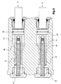
- the limit pressure opens a fill level relief valve shown in Fig. 2 24 and connects the filling stage 14 to a storage container 26.
- the check valve 20 and the closes Pressure in pressure stage 16 increases with increasing Brake pedal force continues to increase, so that the desired braking effect entry.
- the filling level relief valve 24 shown in FIG. 2 contains a large cylinder body as valve element 28 Diameter and one as a relief pressure piston 30 trained cylinder body of smaller diameter.
- the Valve element 28 is in a larger cylinder bore 32 and the relief pressure piston 30 is in a cylinder bore 34 smaller diameter can be moved lengthways.
- Both Cylinder bodies 28, 30 are commercially available Needle roller bearings that comply with high manufacturing tolerances.
- the Cylinder bores 32, 34 are aligned with one another and form one Stepped bore. They point in terms of their axial Alignment with a high level of manufacturing precision finely grated. They form with the associated cylinder bodies 28, 30 high precision sliding seals, one Prevent the passage of liquids as much as possible.
- the stepped bore 32, 34 is through a plug 36 locked.
- the plug 36 carries one into the cylinder bore 32 protruding approach 38, the axial movement of the Valve element 28 limited. Is concentric to approach 38 a helical compression spring 40 arranged between the plug 36 and the valve element 28 is clamped and that Valve element 28 pushes to the left, away from the plug 36.
- the larger cylinder bore 32 is via a sump channel 42 and a relief channel 44 with the reservoir 26 and over an only partially recognizable filling stage channel 46 with the Fill level 14 connected.
- the sump channel 42 opens into the larger one Cylinder bore 32 in the area of the stopper 38.
- the Sump channel 42 is not through valve element 28 lockable so that the fluid pressure in the reservoir always on the right end of the valve element 28 pending.
- the filling stage channel 46 opens into the larger one Cylinder bore 32 in an area to the left of that Valve element 28 so that the fluid pressure in the Fill level 14 constantly on the left side of the Valve element 28 bears.
- the relief channel 44 is closed by the valve element 28 when this is in the rest position shown in Fig. 2.
- the valve element 28 moves to the right and opens the Relief channel 44.
- the opening limit pressure depends on the pressure of the reservoir 26 and the force of the compression spring 40.
- the left end 47 of the smaller cylinder bore 34 stands with the brake compensation channel 19 in connection. If the brake piston 10, 12 is actuated and the second control edge 21 den Brake equalization channel 19 connects to pressure stage 16 on the left end face of the relief pressure piston 30 Pressure of pressure level 16 on. On the right front of the Relief pressure piston 30, however, the pressure of the Fill level 14. If the pressure of pressure levels 16 is greater than the pressure of the filling stage 14 becomes the relief pressure piston 30 pressed against the valve element 28. With increasing Pressure difference, the counterforce of the compression spring 40 is increasing compensated so that the required for the valve element 28 Opening pressure decreases and the pressure of the filling stage 14 over the Control edge 49 of the valve element 28 and the relief channel 44 will be gradually dismantled.
- the two compression springs 40 of the two valve units 11, 13 can have somewhat different spring constants, so that the Valve elements 28 react differently and not open at the same time but at different times. This leads to a further stabilization of the braking force characteristic, so that the transition from the filling level to the pressure level for the Operator is no longer noticeable.
- the plug 36 and / or the compression springs 40 of the two valve units 11, 13 different lengths have, so that the axial rest position, d. H. the situation in depressurized state of the two valve elements 28 is different.
- the filling stage 14 is with the reservoir 26 on Suction valve 52 in connection, via which when loosening the Brake pedal brake fluid from the reservoir 26 in the Filling stage 14 is sucked so that the piston 10 in its Starting position can return.
Abstract
Description
Die Erfindung betrifft ein zweistufiges Ventil, insbesondere ein Bremsventil, mit zwei Querschnittsstufen, deren Wirkungsquerschnitte bei einer Ventilbetätigung nacheinander wirksam werden, indem zunächst ein Druckraum größeren Wirkungsquerschnitts, die sogenannte Füllstufe, zum Befüllen einer Anlage verwendet wird und dann ein Druckraum kleineren Wirkungsquerschnitts, die sogenannte Druckstufe, zum Aufbringen des Arbeitsdrucks eingesetzt wird. Zwischen der Füllstufe und einem Vorratsbehälter ist ein Füllstufenentlastungsventil angeordnet, welches ein Ventilelement und einen auf das Ventilelement einwirkenden Entlastungskolben aufweist. Das Ventilelement ist einerseits dem Druck im Vorratsbehälter sowie einer Federkraft und andererseits dem Druck in der Füllstufe ausgesetzt. Es öffnet eine Verbindung zwischen der Füllstufe und dem Vorratsbehälter, wenn ein in der Füllstufe vorgebbarer Grenzdruck erreicht und überschritten wird. Der Entlastungskolben ist einenends dem Druck im Vorratsbehälter ausgesetzt und kann anderenends dem Druck in der Druckstufe ausgesetzt werden. Er liegt mit einem freien Ende an dem Ventilelement an, um mit steigendem Differenzdruck zwischen der Druckstufe und der Füllstufe das Ventilelement in Öffnungsrichtung zu drängen.The invention relates to a two-stage valve, in particular a brake valve, with two cross-sectional levels, the Cross sections with one valve actuation one after the other take effect by first enlarging a pressure room Cross section, the so-called filling level, for filling a system is used and then a pressure room smaller Cross section, the so-called pressure stage, to Applying the working pressure is used. Between the Filling level and a storage container is a Filling level relief valve arranged, which a Valve element and one acting on the valve element Relief piston has. The valve element is on the one hand the pressure in the reservoir and a spring force and on the other hand exposed to the pressure in the filling stage. It opens a connection between the filling level and the Storage container if one that can be specified in the filling level Limit pressure is reached and exceeded. The Relief piston is one end of the pressure in the reservoir exposed and can at the other end the pressure in the compression stage get abandoned. It has a free end on that Valve element in order to with increasing differential pressure between the pressure stage and the filling stage the valve element in To push opening direction.
Ein derartiges als Bremsventil ausgebildetes Ventil geht aus der US-A-4,455,831 hervor, bei dem das Ventilelement als Kugel ausgebildet ist, welche mit einem Ventilsitz im Ventilgehäuse zusammenwirkt. Das Ventilelement öffnet, wenn der Fluiddruck innerhalb der Füllstufe einen bestimmten Stellwert erreicht. Der Entlastungskolben ist ein Stufenkolben dessen dickerer Kolbenabschnitt in einer Zylinderbohrung geführt ist und eine Ringnut aufweist, die eine Dichtung aufnimmt. Der dünnere Kolbenabschnitt greift mit seiner Stirnseite an der Kugel an. Bei steigendem Druck in der Druckstufe wird der Entlastungskolben mit zunehmender Kraft gegen die Kugel in Öffnungsrichtung gedrückt. Hierdurch soll ein konstanter Betrieb selbst bei plötzlicher Bremsbetätigung garantiert werden. Durch die Verwendung der Dichtung am Entlastungskolben kommt es jedoch zu reibungsbedingten Beeinträchtigungen wie Hysterese und "schwammiges" Ansprechverhalten.Such a valve designed as a brake valve goes out US-A-4,455,831, in which the valve element as a ball is formed, which has a valve seat in the valve housing interacts. The valve element opens when the fluid pressure reached a certain manipulated value within the filling level. The relief piston is a stepped piston whose thicker Piston section is guided in a cylinder bore and a Has annular groove that receives a seal. The thinner The end of the piston engages with the ball. With increasing pressure in the pressure stage the Relief piston with increasing force against the ball in Opening direction pressed. This is said to be a constant Operation guaranteed even when the brakes are applied suddenly become. By using the seal on the relief piston however, there are friction-related impairments such as Hysteresis and "spongy" response.
In der EP-A-0 534 309 wird ein zweistufiges Bremsventil beschrieben, bei dem zwischen der Füllstufe und dem Vorratsbehälter ein Rückschlagventil angeordnet ist, welches eine Kugel enthält, die durch die Kraft einer Feder auf einen Ventilsitz gedrückt wird und bei einem vorgebbaren Grenzdruck öffnet. Um die erforderliche Betätigungskraft für das Bremsventil klein zu halten und eine sprunghafte Änderung des Arbeitsdrucks während des Übergangs zwischen Füllstufe und Druckstufe zu vermeiden, ist die Schließkraft der Feder in Abhängigkeit des Drucks in der Druckstufe steuerbar, in dem dieser Druck auf einen Steuerschieber wirkt, der seinerseits die Feder entlastet. Auch bei dieser Lösung sind Dichtungen vorgesehen, um Leckagen zu vermeiden, was die erwähnten Nachteile mit sich bringt.EP-A-0 534 309 describes a two-stage brake valve described, in which between the filling level and the Reservoir a check valve is arranged, which contains a ball by the force of a spring on one Valve seat is pressed and at a predetermined limit pressure opens. To the required operating force for the Keep the brake valve small and make a sudden change in the Working pressure during the transition between filling level and To avoid pressure level, the closing force of the spring is in Dependence of the pressure in the pressure stage controllable in the this pressure acts on a spool, which in turn relieved the spring. Seals are also used with this solution provided to avoid leakage what the mentioned Brings disadvantages.
Die der Erfindung zugrunde liegende Aufgabe wird darin gesehen, ein Ventil der eingangs genannten Art anzugeben, durch welches sich die eingangs genannten Nachteile vermeiden lassen. Insbesondere soll das Ventil ein direktes Ansprechverhalten und ein reduziertes Hysterese-Verhalten aufweisen.The object underlying the invention is seen in to specify a valve of the type mentioned, through which the disadvantages mentioned above can be avoided. In particular, the valve should have a direct response and have a reduced hysteresis behavior.
Die Aufgabe wird erfindungsgemäß durch die Lehre eines der
Patentansprüche 1 oder 7 gelöst. Weitere vorteilhafte
Ausgestaltungen und Weiterbildungen der Erfindung gehen aus den
Unteransprüchen hervor.The object is achieved by teaching one of the
Bei dem erfindungsgemäßen Ventil sind sowohl das Ventilelement als auch der Entlastungskolben als Zylinderkörper ausgebildet. Jeder dieser Zylinderkörper ist in einer zugehörigen Zylinderbohrung des Ventilkörpers nach Art einer Gleitpassung geführt. Als Gleitpassung eignet sich eine Spielpassung, bei der der Zwischenraum zwischen dem Zylinderkolben und der zugehörigen Bohrung so gering ist, dass ein Flüssigkeitsdurchtritt weitgehend vermieden wird, sodass kein Dichtelement verwendet werden muss, und dennoch ein leichtes Verschieben des Zylinderkolbens möglich ist. Die Bohrungen werden vorzugsweise mit Reibahle feingerieben. Des weiteren werden vorzugsweise relativ lange Zylinderkörper verwendet. Dadurch bildet sich zwischen der Bohrung und dem Zylinderkörper ein langer Kanal mit einer großen Dichtlänge aus, die den Flüssigkeitsdurchtritt erschwert.In the valve according to the invention, both the valve element as well as the relief piston designed as a cylinder body. Each of these cylinder bodies is in an associated one Cylinder bore of the valve body in the manner of a sliding fit guided. A clearance fit is suitable as a sliding fit the the space between the cylinder piston and the associated hole is so small that a Liquid passage is largely avoided, so no Sealing element must be used, and yet a lightweight Moving the cylinder piston is possible. The holes are preferably finely ground with a reamer. Furthermore relatively long cylinder bodies are preferably used. This forms between the hole and the Cylinder body a long channel with a large sealing length , which makes it difficult for liquid to pass through.
Durch den Wegfall der Dichtungselemente reagiert das Ventil in seinem Ansprechverhalten unmittelbar auf Betätigungskräfte. Das Hysterese-Verhalten wird erheblich reduziert und die Bremskraft ist besser dosierbar. Des weiteren weist das erfindungsgemäße Ventil mit seinem Füllstufenentlastungsventil einen sehr einfachen, kostengünstig herstellbaren, aus wenigen Bauteilen bestehenden Aufbau auf.By eliminating the sealing elements, the valve reacts in its response behavior directly to actuation forces. The Hysteresis behavior is significantly reduced and the braking force is easier to dose. Furthermore, the invention Valve with its filling level relief valve a very simple, inexpensive to manufacture, from a few components existing structure.
Eine besonders vorteilhafte Ausbildung der Erfindung ergibt sich dadurch, dass wenigstens einer der beiden Zylinderkörper eine Nadellagerrolle ist. Damit besteht der Zylinderkörper aus einem handelsüblichen hochpräzisen Bauteil, das als Massenprodukt im Handel preiswert erhältlich ist. Da Nadellagerrollen meist relativ lang sind, ergibt sich eine große Dichtlänge, die gemeinsam mit der Passgenauigkeit der feingeriebenen Bohrung eine Dichtwirkung hat, die ohne zusätzliches Dichtelement, insbesondere ohne Elastomerdichtung, auskommt.A particularly advantageous embodiment of the invention results is characterized in that at least one of the two cylinder bodies is a needle roller. The cylinder body thus consists of a commercially available high-precision component, which as Mass product is commercially available inexpensively. There Needle roller bearings are usually relatively long, one results large sealing length, which together with the accuracy of fit finely rubbed hole has a sealing effect without additional sealing element, especially without an elastomer seal, gets along.
Es ist von Vorteil, wenn die Mittellinien der Zylinderbohrungen, die das Ventilelement bzw. den Entlastungskolben aufnehmen, miteinander fluchten. Dabei sind die Zylinderbohrungen nach Art einer Stufenbohrung ausgebildet, die sich auf einfache Weise präzise herstellen lässt.It is advantageous if the center lines of the Cylinder bores that the valve element or the Pick up the relief piston, align with each other. Are there the cylinder bores are designed in the manner of a stepped bore, that can be precisely manufactured in a simple manner.
Vorzugsweise mündet in die dem Ventilelement zugeordnete Zylinderbohrung ein mit dem Vorratsbehälter verbundener Entlastungsskanal. An der dem Entlastungskolben zugewandten Seite des Ventilelements ist eine mit dem Entlastungsskanal zusammenwirkende Steuerkante ausgebildet, über die bei Erreichen des Grenzdruckes eine Verbindung zwischen der Füllstufe und dem Vorratsbehälter hergestellt wird.Preferably opens into the one assigned to the valve element Cylinder bore connected to the reservoir Entlastungsskanal. On the discharge piston facing Side of the valve element is one with the relief channel cooperating control edge formed over the at Reaching the limit pressure a connection between the Filling stage and the reservoir is made.
Es hat sich als besonders vorteilhaft erwiesen, in dem Entlastungsskanal wenigstens eine Blende anzuordnen oder eine Blende im Entlastungsskanal auszubilden. Hierdurch wird besonders bei plötzlicher Ventilbetätigung, wenn sich das Füllstufenentlastungsventil rasch öffnet, das Ansprechverhalten in der Übergangsphase zwischen Füllstufe und Druckstufe verstetigt, sodass sprunghafte Ventilreaktionen vermieden werden können.It has proven to be particularly advantageous in the Relief channel to arrange at least one aperture or one Form the orifice in the relief duct. This will especially in the event of sudden valve actuation, if that is Filling level relief valve opens quickly, the response in the transition phase between filling level and pressure level steady so that sudden valve reactions are avoided can be.
Es ist zweckmäßig, einen Anschlag vorzusehen, der den Öffnungshub des Ventilelements begrenzt und damit nach Beendigung einer Ventilbetätigung ein rasches Rückkehren des Ventilelements in seine Ausgangsstellung ermöglicht.It is useful to provide a stop that the Opening stroke of the valve element limited and thus after Termination of a valve actuation a quick return of the Allows valve element in its starting position.
Erfingunsgemäße Ventile finden in vorteilhafter Weise bei Fahrzeugen, insbesondere bei landwirtschaftlichen oder industriellen Fahrzeugen wie Ackerschleppern, als Bremsventile Anwendung. Dabei ist eine rechte und eine linke Fahrzeugbremse vorgesehen, die je ein erfindungsgemäß ausgebildetes Ventil enthält. Über einen Bremsausgleichskanal stehen die jeweiligen Druckstufenseiten der beiden die Entlastungskolben aufnehmenden Zylinderbohrungen hydraulisch miteinander in Verbindung. Dies ermöglicht es, dass beide Bremskreise abhängig vom jeweiligen Bremspedalweg miteinander gekoppelt werden, um sicherzustellen, dass beide Bremskreise mit demselben Druck versorgt werden und ein "Schiefziehen" beim Bremsen vermieden wird.Valves in accordance with the invention are advantageously used in Vehicles, especially in agricultural or industrial vehicles such as agricultural tractors, as brake valves Application. There is a right and a left vehicle brake provided, each a valve designed according to the invention contains. The respective stand over a brake compensation channel Compression sides of the two receiving the relief pistons Cylinder bores hydraulically connected to each other. This enables both brake circuits to be dependent on the respective Brake pedal travel are coupled together to ensure that both brake circuits are supplied with the same pressure and a "skewing" when braking is avoided.
Es ist von besonderem Vorteil, wenn die beiden Füllstufenentlastungsventile gegeneinander verstimmt sind und bei unterschiedlichen Drücken öffnen. Dies kann beispielsweise ausdrücklich durch Verwendung von Federn mit unterschiedlicher Federkonstante und/oder durch die Vorgabe unterschiedlicher Ruhelagen für die beiden Ventilelemente erfolgen. Hierdurch lässt sich der Umsteuervorgang zwischen Füllstufe und Druckstufe über einen größeren Druckbereich ausdehnen und verstetigen, so dass für die Bedienungsperson der Umschaltvorgang nicht mehr spürbar ist.It is particularly beneficial if the two Filling level relief valves are out of tune with each other and open at different pressures. For example expressly by using springs with different Spring constant and / or by specifying different ones Rest positions for the two valve elements. hereby can the reversal process between filling level and Extend pressure level over a larger pressure range and steady so that for the operator of the Switching process is no longer noticeable.
Anhand der Zeichnung, die ein Ausführungsbeispiel der Erfindung zeigt, werden nachfolgend die Erfindung sowie weitere Vorteile und vorteilhafte Weiterbildungen und Ausgestaltungen der Erfindung näher beschrieben und erläutert.Using the drawing, which is an embodiment of the invention shows, the invention and further advantages are below and advantageous developments and refinements of Invention described and explained in more detail.
Es zeigt:
- Fig. 1
- die Schnittdarstellung eines erfindungsgemäßen zweistufigen Bremsventils entlang der in Fig. 4 dargestellten Schnittlinie 1-1,
- Fig. 2
- die Schnittdarstellung des Bremsventils gemäß Fig. 1 entlang der in Fig. 4 dargestellten Schnittlinie 2-2,
- Fig. 3
- die Schnittdarstellung des Bremsventils gemäß Fig. 1 entlang der in Fig. 4 dargestellten Schnittlinie 3-3 und
- Fig. 4
- die Teilschnittdarstellung des Bremsventils gemäß Fig. 1 entlang der in Fig. 1 dargestellten Schnittlinie 4-4.
- Fig. 1
- 4 shows the sectional illustration of a two-stage brake valve according to the invention along the sectional line 1-1 shown in FIG. 4,
- Fig. 2
- 1 along the line 2-2 shown in FIG. 4,
- Fig. 3
- the sectional view of the brake valve of FIG. 1 along the section line 3-3 shown in Fig. 4 and
- Fig. 4
- the partial sectional view of the brake valve of FIG. 1 along the section line 4-4 shown in Fig. 1.
Die Figuren zeigen ein durch Eigenkraft (manuell) betätigtes
Bremsventil für einen Ackerschlepper, welches zwei
Ventileinheiten 11, 13 enthält, die jeweils durch ein
zugehöriges rechtes bzw. linkes Bremspedal betätigbar sind, um
auf bekannte Weise eine Lenkbremsfunktion zu ermöglichen. Jede
Ventileinheit 11, 13 enthält zwei Übersetzungsstufen, die die
Kombination von geringem Pedalweg und niedrigen Kräften
erlauben.The figures show a self-operated (manual)
Brake valve for a tractor, which two
Includes
In Fig. 1 ist der Stufenhauptzylinder einer der beiden
Ventileinheiten 11, 13 dargestellt, welcher zwei Kolben
unterschiedlichen Durchmessers aufnimmt. Hierbei handelt es
sich um einen Füllkolben 10 großen Durchmessers und einen
Druckkolben 12 kleineren Durchmessers. Die den beiden Kolben
10, 12 zugeordneten Druckräume werden mit Füllstufe 14 und
Druckstufe 16 bezeichnet.In Fig. 1, the step master cylinder is one of the two
Durch Betätigung des nicht dargestellten Bremspedals wird eine
Kraft auf das Kolbenende 18 ausgeübt und der Füllkolben 10
gemeinsam mit dem Druckkolben 12 nach links verschoben. Dabei
wird durch eine erste Steuerkante 15 des Druckkolbens 12 ein
Kanal 17, der die Druckstufe 16 mit einem Vorratsbehälter 26
verbindet, verschlossen. Bei weiterer Kolbenbewegung wird durch
eine zweite Steuerkante 21 des Druckkolbens 12 ein
Bremsausgleichskanal 19 mit der Druckstufe 16 verbunden. Der
Bremsausgleichskanal 19 verbindet die Stufenhauptzylinder der
beiden Ventileinheiten 11, 13 miteinander.By pressing the brake pedal, not shown, a
Force is exerted on the
Mit der Kolbenbewegung nach links baut sich in der Füllstufe 14
ein Druck auf, durch den ein Rückschlagventil 20 geöffnet wird,
so dass Bremsflüssigkeit von der Füllstufe 14 durch das
Rückschlagventil 20, die Druckstufe 16 und einen Fitting 22 zur
nicht dargestellten Bremse fließt und eine Bremsscheibe zur
Anlage bringt. Wenn die Bremsscheibe anliegt, kann keine
nennenswerte Flüssigkeitsmenge mehr abfließen, so dass der
Druck in der Füllstufe 14 und in der Druckstufe 16 bis zu einem
Grenzdruck weiter ansteigt. Beim Erreichen des Grenzdrucks
öffnet ein in Fig. 2 dargestelltes Füllstufenentlastungsventil
24 und verbindet die Füllstufe 14 mit einem Vorratsbehälter 26.
Etwa zur gleichen Zeit schließt das Rückschlagventil 20 und der
Druck in der Druckstufe 16 steigt mit zunehmender
Bremspedalkraft weiter an, so dass der erwünschte Bremseffekt
eintritt. With the piston movement to the left, the filling
Das in Fig. 2 dargestellte Füllstufenentlastungsventil 24
enthält als Ventilelement 28 einen Zylinderkörper großen
Durchmessers und einen als Entlastungsdruckkolben 30
ausgebildeten Zylinderkörper kleineren Durchmessers. Das
Ventilelement 28 ist in einer größeren Zylinderbohrung 32 und
der Entlastungsdruckkolben 30 ist in einer Zylinderbohrung 34
kleineren Durchmessers längs verschiebbar. Bei den
Zylinderkörpern 28, 30 handelt es sich um handelsübliche
Nadellagerrollen, die hohe Fertigungstoleranzen einhalten. Die
Zylinderbohrungen 32, 34 fluchten miteinander und bilden eine
Stufenbohrung. Sie weisen hinsichtlich ihrer axialen
Ausrichtung eine hohe Fertigungspräzision auf und sind
feingerieben. Sie bilden mit den zugehörigen Zylinderkörpern
28, 30 Gleitdichtungen hoher Genauigkeit, die einen
Flüssigkeitsdurchtritt weitestgehend verhindern.The filling
Die Stufenbohrung 32, 34 ist durch einen Stopfen 36
verschlossen. Der Stopfen 36 trägt einen in die Zylinderbohrung
32 ragenden Ansatz 38, der die axiale Bewegung des
Ventilelements 28 begrenzt. Konzentrisch zum Ansatz 38 ist
eine schraubenförmige Druckfeder 40 angeordnet, die zwischen
dem Stopfen 36 und dem Ventilelement 28 eingespannt ist und das
Ventilelement 28 nach links, von dem Stopfen 36 wegdrückt.The stepped bore 32, 34 is through a
Die größere Zylinderbohrung 32 ist über einen Sumpfkanal 42 und
einen Entlastungskanal 44 mit dem Vorratsbehälter 26 und über
einen nur teilweise erkennbaren Füllstufenkanal 46 mit der
Füllstufe 14 verbunden. Der Sumpfkanal 42 mündet in die größere
Zylinderbohrung 32 im Bereich des Stopfenansatzes 38. Der
Sumpfkanal 42 ist nicht durch das Ventilelement 28
verschließbar, so dass der Flüssigkeitsdruck im Vorratsbehälter
ständig an der rechten Stirnseite des Ventilelements 28
ansteht. Der Füllstufenkanal 46 mündet in die größere
Zylinderbohrung 32 in einem Bereich links neben dem
Ventilelement 28, so dass der Flüssigkeitsdruck in der
Füllstufe 14 ständig auf der linken Stirnseite des
Ventilelements 28 lastet. Der Entlastungskanal 44 wird hingegen
durch das Ventilelement 28 verschlossen, wenn dieses sich in
der in Fig. 2 dargestellten Ruhestellung befindet. Wird jedoch
der Druck in der Füllstufe 14 so groß, dass er den Druck des
Vorratsbehälters 26 und die Kraft der Druckfeder 40 überwindet,
verschiebt sich das Ventilelement 28 nach rechts und öffnet den
Entlastungskanal 44. Der Öffnungsgrenzdruck hängt von dem Druck
des Vorratsbehälters 26 und der Kraft der Druckfeder 40 ab.The larger cylinder bore 32 is via a
Das linke Ende 47 der kleineren Zylinderbohrung 34 steht mit
dem Bremsausgleichskanal 19 in Verbindung. Wenn der Bremskolben
10, 12 betätigt ist und die zweite Steuerkante 21 den
Bremsausgleichskanal 19 mit der Druckstufe 16 verbindet, steht
an der linken Stirnfläche des Entlastungsdruckkolbens 30 der
Druck der Druckstufe 16 an. Auf der rechten Stirnseite des
Entlastungsdruckkolbens 30 lastet hingegen der Druck der
Füllstufe 14. Wenn der Druck der Druckstufen 16 größer ist als
der Druck der Füllstufe 14 wird der Entlastungsdruckkolben 30
gegen das Ventilelement 28 gedrückt. Mit steigender
Druckdifferenz wird die Gegenkraft der Druckfeder 40 zunehmend
kompensiert, so dass der für das Ventilelement 28 erforderliche
Öffnungsdruck abnimmt und der Druck der Füllstufe 14 über die
Steuerkante 49 des Ventilelements 28 und den Entlastungskanal
44 sukzessive abgebaut wird.The
Während eines Bremsvorgangs, bei dem das Bremspedal mit
zunehmender Kraft betätigt wird und die Kolben 10, 12 nach
links verschoben werden, wird automatisch von der Füllstufe auf
die Druckstufe umgeschaltet, indem bei einem vorgegebenen Druck
das Rückschlagventil 20 schließt. Bei der Umschaltung geht der
Verlauf der Bremskraftkennlinie, die die Abhängigkeit des
Bremsdrucks von der Bremspedalkraft wiedergibt, von einer
Füllkennlinie auf eine Druckkennlinie über.During a braking operation, in which the brake pedal with
increasing force is actuated and the
Die beschriebene Entlastung des Ventilelements 28 hat zur
Folge, dass beim Übergang des Bremsdruckaufbaus durch die
Füllstufe 14 zum Bremsdruckaufbau durch die Druckstufe 16 kein
schroffer Knick in der Bremskraftkennlinie auftritt, der zu
einem für die Bedienungsperson unerwarteten Anstieg der
Bremswirkung führen kann.The described relief of the
Bei rascher Bremsbetätigung erfolgt ein schneller Übergang von
der Füllstufe zur Druckstufe. Damit steigt die auf dem
Entlastungsdruckkolben 30 lastende Druckdifferenz schnell an
und verschiebt das Ventilelement 28, so dass der Druck in der
Füllstufe 14 über den Füllstufenkanal 46 und den
Entlastungskanal 44 schnell abgebaut wird, was zu einer
weiteren Beschleunigung des Druckdifferenzanstiegs führt. Die
durch das Bremspedal aufgebrachte Bremskraft wirkt damit sehr
bald fast ausschließlich auf die Druckstufe 16 und wird nicht
durch ein "Druckpolster" in der Füllstufe gedämpft. Dies kann
zu einem unerwartet schnellen Anstieg der Bremsleistung führen.
Um den Flüssigkeitsabfluss aus der Füllstufe 14 zu verlangsamen
und damit beim Übergang von der Füllstufe zu der Druckstufe
eine übermäßige Änderung im Verlauf der Bremskraftkennlinie zu
vermeiden, ist in dem Entlastungskanal 44 eine Blende 50
angeordnet, die den Flüssigkeitsabfluss aus der größeren
Zylinderbohrung 32 begrenzt. Der Effekt der Blende 50 nimmt mit
zunehmender Bremsbetätigungskraft zu.With quick brake application there is a quick transition from
the filling level to the pressure level. So that increases on the
Wie aus Fig. 4 hervorgeht, stehen die Stufenhauptzylinder der
beiden Ventileinheiten 11, 13 durch den Bremsausgleichskanal 19
miteinander in Verbindung. Bei Betätigung beider Bremspedale
werden die Druckkolben 12 beider Ventileinheiten 11, 13
verschoben. Dabei geben die zweiten Steuerkanten 21 der
Druckkolben 16 jeweils eine Öffnung zwischen ihrer Druckstufe
16 und dem Bremsausgleichskanal 19 frei, so dass beide
Druckstufen 16 miteinander verbunden werden. Alle Bremsen sind
damit dem selben Bremsdruck ausgesetzt, wodurch ein
"Schiefziehen" beim Bremsen vermieden wird. Der Bremsdruck wird
über den Bremsausgleichskanal 19 den beiden
Entlastungsdruckkolben 30 mitgeteilt, so dass an beiden
Ventilelementen 28 der gleiche Entlastungsdruck ansteht. Die
beiden Druckfedern 40 der beiden Ventileinheiten 11, 13 können
etwas unterschiedliche Federkonstanten aufweisen, so dass die
Ventilelemente 28 unterschiedlich reagieren und nicht
gleichzeitig sondern zeitlich versetzt öffnen. Dies führt zu
einer weiteren Verstetigung der Bremskraftkennlinie, so dass
der Übergang von der Füllstufe zur Druckstufe für die
Bedienungsperson nicht mehr spürbar ist. Zu dem gleichen Zweck
können auch die Stopfen 36 und/oder die Druckfedern 40 der
beiden Ventileinheiten 11, 13 unterschiedliche Längen
aufweisen, so dass die axiale Ruhelage, d. h. die Lage im
drucklosen Zustand, der beiden Ventilelemente 28
unterschiedlich ist.As can be seen from Fig. 4, the stepped master cylinder
two
Die Füllstufe 14 steht mit dem Vorratsbehälter 26 über ein
Nachsaugventil 52 in Verbindung, über welches beim Lösen des
Bremspedals Bremsflüssigkeit aus dem Vorratsbehälter 26 in die
Füllstufe 14 gesaugt wird, so daß der Kolben 10 in seine
Ausgangsposition zurückkehren kann.The filling
Auch wenn die Erfindung lediglich anhand eines Ausführungsbeispiels beschrieben wurde, erschließen sich für den Fachmann im Lichte der vorstehenden Beschreibung sowie der Zeichnung viele verschiedenartige Alternativen, Modifikationen und Varianten, die unter die vorliegende Erfindung fallen.Even if the invention is based only on one Embodiment has been described, open up for the expert in the light of the above description and the Drawing many different alternatives, modifications and variants which fall under the present invention.
Claims (10)
Applications Claiming Priority (2)
| Application Number | Priority Date | Filing Date | Title |
|---|---|---|---|
| DE10034787A DE10034787A1 (en) | 2000-07-18 | 2000-07-18 | Two stage valve |
| DE10034787 | 2000-07-18 |
Publications (2)
| Publication Number | Publication Date |
|---|---|
| EP1174321A1 true EP1174321A1 (en) | 2002-01-23 |
| EP1174321B1 EP1174321B1 (en) | 2003-05-14 |
Family
ID=7649245
Family Applications (1)
| Application Number | Title | Priority Date | Filing Date |
|---|---|---|---|
| EP01115591A Expired - Lifetime EP1174321B1 (en) | 2000-07-18 | 2001-06-28 | Two-stage valve |
Country Status (7)
| Country | Link |
|---|---|
| US (1) | US6502396B2 (en) |
| EP (1) | EP1174321B1 (en) |
| AT (1) | ATE240228T1 (en) |
| BR (1) | BR0102932A (en) |
| CA (1) | CA2352635A1 (en) |
| DE (2) | DE10034787A1 (en) |
| MX (1) | MXPA01007296A (en) |
Families Citing this family (4)
| Publication number | Priority date | Publication date | Assignee | Title |
|---|---|---|---|---|
| JP4385001B2 (en) * | 2005-03-31 | 2009-12-16 | 日信工業株式会社 | Hydraulic booster |
| CA3023021C (en) * | 2016-05-04 | 2020-12-29 | Ginda New-Tech Co., Ltd. | Hydraulic brake device with a time difference and assembly thereof |
| CN108860036B (en) * | 2018-07-26 | 2023-08-29 | 重庆交通职业学院 | Adjustable damping type hydraulic energy absorption mechanism for automobile anti-collision beam |
| CN112810591A (en) * | 2021-03-05 | 2021-05-18 | 江苏沃得农业机械股份有限公司 | One-way two-stage pressure booster brake pump |
Citations (2)
| Publication number | Priority date | Publication date | Assignee | Title |
|---|---|---|---|---|
| US4455831A (en) * | 1981-04-14 | 1984-06-26 | Akebono Brake Industry Co., Ltd. | Differential master cylinder |
| US5239828A (en) * | 1991-09-27 | 1993-08-31 | Deere & Company | Two-stage valve |
Family Cites Families (1)
| Publication number | Priority date | Publication date | Assignee | Title |
|---|---|---|---|---|
| DE4130832C1 (en) * | 1991-09-17 | 1993-05-13 | Deere & Co., Moline, Ill., Us, Niederlassung Deere & Co. European Office, 6800 Mannheim, De |
-
2000
- 2000-07-18 DE DE10034787A patent/DE10034787A1/en not_active Withdrawn
-
2001
- 2001-06-22 US US09/888,132 patent/US6502396B2/en not_active Expired - Lifetime
- 2001-06-28 DE DE50100240T patent/DE50100240D1/en not_active Expired - Lifetime
- 2001-06-28 EP EP01115591A patent/EP1174321B1/en not_active Expired - Lifetime
- 2001-06-28 AT AT01115591T patent/ATE240228T1/en not_active IP Right Cessation
- 2001-07-06 CA CA002352635A patent/CA2352635A1/en not_active Abandoned
- 2001-07-17 BR BR0102932-0A patent/BR0102932A/en not_active Application Discontinuation
- 2001-07-18 MX MXPA01007296A patent/MXPA01007296A/en unknown
Patent Citations (2)
| Publication number | Priority date | Publication date | Assignee | Title |
|---|---|---|---|---|
| US4455831A (en) * | 1981-04-14 | 1984-06-26 | Akebono Brake Industry Co., Ltd. | Differential master cylinder |
| US5239828A (en) * | 1991-09-27 | 1993-08-31 | Deere & Company | Two-stage valve |
Also Published As
| Publication number | Publication date |
|---|---|
| EP1174321B1 (en) | 2003-05-14 |
| US20020007635A1 (en) | 2002-01-24 |
| CA2352635A1 (en) | 2002-01-18 |
| BR0102932A (en) | 2002-03-05 |
| MXPA01007296A (en) | 2003-05-19 |
| DE50100240D1 (en) | 2003-06-18 |
| DE10034787A1 (en) | 2002-01-31 |
| US6502396B2 (en) | 2003-01-07 |
| ATE240228T1 (en) | 2003-05-15 |
Similar Documents
| Publication | Publication Date | Title |
|---|---|---|
| EP0744009B1 (en) | Multi-stage regulating valve | |
| DE2602050B2 (en) | Hydraulic booster valve, in particular for a hydraulic brake system of a motor vehicle | |
| EP0368120B1 (en) | Valve | |
| DE2558034A1 (en) | PRESSURE REDUCING DEVICE, IN PARTICULAR FOR HYDRAULIC BRAKE SYSTEMS IN MOTOR VEHICLES | |
| DE3133995A1 (en) | PRESSURE VALVE FOR A HYDRAULIC TWO-CIRCUIT BRAKE SYSTEM | |
| DE3116237A1 (en) | Outlet valve device in a rapidly responding master cylinder | |
| EP1174321B1 (en) | Two-stage valve | |
| DE2213367C3 (en) | Pressure reducing valve for pressure medium actuated motor vehicle brake systems | |
| DE3037485A1 (en) | MAIN BRAKE CYLINDER | |
| DE2403430A1 (en) | CONTROL VALVE WITH GRADUATED PRESSURE INCREASE | |
| DE2736095C3 (en) | Control valve for a hydraulic vehicle brake system | |
| EP0534309B1 (en) | Two-step valve | |
| DE3029090C2 (en) | ||
| DE2933878A1 (en) | BRAKE FORCE REGULATOR FOR A HYDRAULIC MOTORCYCLE BRAKE SYSTEM. | |
| DE2508268C3 (en) | Control piston for hydraulic pressure medium sequence controls, in particular for a steering valve of a power steering device of vehicles | |
| DE3836344C2 (en) | ||
| DE2426712B2 (en) | Power steering device for vehicles, in particular those with accumulator steering | |
| DE3138933C2 (en) | Dual-circuit pressure regulator | |
| DE2748698A1 (en) | PRESSURE REGULATING VALVE | |
| DE19525582A1 (en) | Inch brake device | |
| DE19723777A1 (en) | Brake valve | |
| DE2438455A1 (en) | HYDRAULIC BRAKING BOOSTER | |
| DE2433567A1 (en) | BRAKE VALVE FOR TWO BRAKE CIRCUITS TO BE ACTUATED SEPARATELY OR AT THE SAME TIME | |
| DE2436315A1 (en) | HYDRAULIC PRESSURE MEDIUM CONTROL SYSTEM FOR POSITION CONTROL OF A DOUBLE ACTING SERVOMOTOR | |
| DE2949657A1 (en) | Valve for hydraulic servo motor - has two throttles in series in each control line for spring-loaded slide valve |
Legal Events
| Date | Code | Title | Description |
|---|---|---|---|
| PUAI | Public reference made under article 153(3) epc to a published international application that has entered the european phase |
Free format text: ORIGINAL CODE: 0009012 |
|
| AK | Designated contracting states |
Kind code of ref document: A1 Designated state(s): AT BE CH CY DE DK ES FI FR GB GR IE IT LI LU MC NL PT SE TR |
|
| AX | Request for extension of the european patent |
Free format text: AL;LT;LV;MK;RO;SI |
|
| 17P | Request for examination filed |
Effective date: 20020723 |
|
| AKX | Designation fees paid |
Free format text: AT BE CH CY DE DK ES FI FR GB GR IE IT LI LU MC NL PT SE TR |
|
| GRAH | Despatch of communication of intention to grant a patent |
Free format text: ORIGINAL CODE: EPIDOS IGRA |
|
| GRAH | Despatch of communication of intention to grant a patent |
Free format text: ORIGINAL CODE: EPIDOS IGRA |
|
| GRAA | (expected) grant |
Free format text: ORIGINAL CODE: 0009210 |
|
| AK | Designated contracting states |
Designated state(s): AT BE CH CY DE DK ES FI FR GB GR IE IT LI LU MC NL PT SE TR |
|
| PG25 | Lapsed in a contracting state [announced via postgrant information from national office to epo] |
Ref country code: IT Free format text: LAPSE BECAUSE OF FAILURE TO SUBMIT A TRANSLATION OF THE DESCRIPTION OR TO PAY THE FEE WITHIN THE PRESCRIBED TIME-LIMIT;WARNING: LAPSES OF ITALIAN PATENTS WITH EFFECTIVE DATE BEFORE 2007 MAY HAVE OCCURRED AT ANY TIME BEFORE 2007. THE CORRECT EFFECTIVE DATE MAY BE DIFFERENT FROM THE ONE RECORDED. Effective date: 20030514 Ref country code: FR Free format text: LAPSE BECAUSE OF FAILURE TO SUBMIT A TRANSLATION OF THE DESCRIPTION OR TO PAY THE FEE WITHIN THE PRESCRIBED TIME-LIMIT Effective date: 20030514 Ref country code: NL Free format text: LAPSE BECAUSE OF FAILURE TO SUBMIT A TRANSLATION OF THE DESCRIPTION OR TO PAY THE FEE WITHIN THE PRESCRIBED TIME-LIMIT Effective date: 20030514 Ref country code: FI Free format text: LAPSE BECAUSE OF FAILURE TO SUBMIT A TRANSLATION OF THE DESCRIPTION OR TO PAY THE FEE WITHIN THE PRESCRIBED TIME-LIMIT Effective date: 20030514 Ref country code: IE Free format text: LAPSE BECAUSE OF FAILURE TO SUBMIT A TRANSLATION OF THE DESCRIPTION OR TO PAY THE FEE WITHIN THE PRESCRIBED TIME-LIMIT Effective date: 20030514 Ref country code: GB Free format text: LAPSE BECAUSE OF FAILURE TO SUBMIT A TRANSLATION OF THE DESCRIPTION OR TO PAY THE FEE WITHIN THE PRESCRIBED TIME-LIMIT Effective date: 20030514 Ref country code: TR Free format text: LAPSE BECAUSE OF FAILURE TO SUBMIT A TRANSLATION OF THE DESCRIPTION OR TO PAY THE FEE WITHIN THE PRESCRIBED TIME-LIMIT Effective date: 20030514 |
|
| REG | Reference to a national code |
Ref country code: GB Ref legal event code: FG4D Free format text: NOT ENGLISH |
|
| REG | Reference to a national code |
Ref country code: CH Ref legal event code: EP |
|
| REG | Reference to a national code |
Ref country code: IE Ref legal event code: FG4D Free format text: GERMAN |
|
| REF | Corresponds to: |
Ref document number: 50100240 Country of ref document: DE Date of ref document: 20030618 Kind code of ref document: P |
|
| PG25 | Lapsed in a contracting state [announced via postgrant information from national office to epo] |
Ref country code: AT Free format text: LAPSE BECAUSE OF NON-PAYMENT OF DUE FEES Effective date: 20030628 Ref country code: LU Free format text: LAPSE BECAUSE OF NON-PAYMENT OF DUE FEES Effective date: 20030628 Ref country code: CY Free format text: LAPSE BECAUSE OF FAILURE TO SUBMIT A TRANSLATION OF THE DESCRIPTION OR TO PAY THE FEE WITHIN THE PRESCRIBED TIME-LIMIT Effective date: 20030628 |
|
| PG25 | Lapsed in a contracting state [announced via postgrant information from national office to epo] |
Ref country code: MC Free format text: LAPSE BECAUSE OF NON-PAYMENT OF DUE FEES Effective date: 20030630 |
|
| PG25 | Lapsed in a contracting state [announced via postgrant information from national office to epo] |
Ref country code: GR Free format text: LAPSE BECAUSE OF FAILURE TO SUBMIT A TRANSLATION OF THE DESCRIPTION OR TO PAY THE FEE WITHIN THE PRESCRIBED TIME-LIMIT Effective date: 20030814 Ref country code: DK Free format text: LAPSE BECAUSE OF FAILURE TO SUBMIT A TRANSLATION OF THE DESCRIPTION OR TO PAY THE FEE WITHIN THE PRESCRIBED TIME-LIMIT Effective date: 20030814 Ref country code: PT Free format text: LAPSE BECAUSE OF FAILURE TO SUBMIT A TRANSLATION OF THE DESCRIPTION OR TO PAY THE FEE WITHIN THE PRESCRIBED TIME-LIMIT Effective date: 20030814 Ref country code: SE Free format text: LAPSE BECAUSE OF FAILURE TO SUBMIT A TRANSLATION OF THE DESCRIPTION OR TO PAY THE FEE WITHIN THE PRESCRIBED TIME-LIMIT Effective date: 20030814 |
|
| PG25 | Lapsed in a contracting state [announced via postgrant information from national office to epo] |
Ref country code: ES Free format text: LAPSE BECAUSE OF FAILURE TO SUBMIT A TRANSLATION OF THE DESCRIPTION OR TO PAY THE FEE WITHIN THE PRESCRIBED TIME-LIMIT Effective date: 20030825 |
|
| NLV1 | Nl: lapsed or annulled due to failure to fulfill the requirements of art. 29p and 29m of the patents act | ||
| GBV | Gb: ep patent (uk) treated as always having been void in accordance with gb section 77(7)/1977 [no translation filed] |
Effective date: 20030514 |
|
| BERE | Be: lapsed |
Owner name: *DEERE & CY Effective date: 20030630 |
|
| REG | Reference to a national code |
Ref country code: IE Ref legal event code: FD4D Ref document number: 1174321E Country of ref document: IE |
|
| PLBE | No opposition filed within time limit |
Free format text: ORIGINAL CODE: 0009261 |
|
| STAA | Information on the status of an ep patent application or granted ep patent |
Free format text: STATUS: NO OPPOSITION FILED WITHIN TIME LIMIT |
|
| 26N | No opposition filed |
Effective date: 20040217 |
|
| EN | Fr: translation not filed | ||
| PG25 | Lapsed in a contracting state [announced via postgrant information from national office to epo] |
Ref country code: CH Free format text: LAPSE BECAUSE OF NON-PAYMENT OF DUE FEES Effective date: 20050630 Ref country code: LI Free format text: LAPSE BECAUSE OF NON-PAYMENT OF DUE FEES Effective date: 20050630 |
|
| REG | Reference to a national code |
Ref country code: CH Ref legal event code: PL |
|
| PG25 | Lapsed in a contracting state [announced via postgrant information from national office to epo] |
Ref country code: BE Free format text: LAPSE BECAUSE OF NON-PAYMENT OF DUE FEES Effective date: 20030630 |
|
| PGFP | Annual fee paid to national office [announced via postgrant information from national office to epo] |
Ref country code: DE Payment date: 20200520 Year of fee payment: 20 |
|
| REG | Reference to a national code |
Ref country code: DE Ref legal event code: R071 Ref document number: 50100240 Country of ref document: DE |