EP1174222A2 - Rotary impact tool having a twin hammer mechanism - Google Patents
Rotary impact tool having a twin hammer mechanism Download PDFInfo
- Publication number
- EP1174222A2 EP1174222A2 EP01306148A EP01306148A EP1174222A2 EP 1174222 A2 EP1174222 A2 EP 1174222A2 EP 01306148 A EP01306148 A EP 01306148A EP 01306148 A EP01306148 A EP 01306148A EP 1174222 A2 EP1174222 A2 EP 1174222A2
- Authority
- EP
- European Patent Office
- Prior art keywords
- anvil
- hammer
- annular ring
- hollow
- diameter
- Prior art date
- Legal status (The legal status is an assumption and is not a legal conclusion. Google has not performed a legal analysis and makes no representation as to the accuracy of the status listed.)
- Withdrawn
Links
Images



Classifications
-
- B—PERFORMING OPERATIONS; TRANSPORTING
- B25—HAND TOOLS; PORTABLE POWER-DRIVEN TOOLS; MANIPULATORS
- B25B—TOOLS OR BENCH DEVICES NOT OTHERWISE PROVIDED FOR, FOR FASTENING, CONNECTING, DISENGAGING, OR HOLDING
- B25B21/00—Portable power-driven screw or nut setting or loosening tools; Attachments for drilling apparatus serving the same purpose
- B25B21/02—Portable power-driven screw or nut setting or loosening tools; Attachments for drilling apparatus serving the same purpose with means for imparting impact to screwdriver blade or nut socket
Definitions
- the present invention relates generally to new and novel improvements in a rotary impact tool having a twin hammer mechanism. More particularly, the present invention relates to a rotary impact tool having a twin hammer mechanism, such as a air driven impact wrench, which is capable of delivering, in rapid succession, a series of rotary impact forces or blows. Such tools have typically been used to tighten or loosen high torque nut or bolts or similar items.
- a conventional rotary impact wrench mechanism known as a "swinging weight” mechanism, is disclosed in US-A-2 285 638 for an “Impact Clutch.” While this mechanism is rather inefficient, it is one of the first to deliver rotary force in a series of impact blows.
- the ability to deliver a series of impact blows provides a human operator with an advantage in that the human operator can physically hold the impact wrench while delivering high torque forces in short burst or impacts.
- the advantage of applying short duration high torque impact blows is that a normal human being can continue to physically hold the tool while applying high torque forces. If such high torque forces were applied continuously by the tool, an opposite continuous reaction force on the tool would be too great to allow the tool to be held by a normal human being.
- a rotary impact tool having a twin hammer mechanism
- said rotary impact tool comprising a housing, a hollow cage member or carrier member positioned within said housing, a first hollow hammer member and a second hollow hammer member pivotally positioned within said hollow cage member or carrier member so that said first and second hammer members rotate with said cage or carrier member under drive from an air motor output shaft and an anvil positioned inside said first and second hammer members, said anvil being able to rotate relative to said first and second hammer members, and said anvil including a forward anvil lug and a rearward anvil lug.
- anvil for a rotary impact tool having a twin hammer mechanism, said anvil comprising a forward anvil lug, a rearward anvil lug coaxial with said forward anvil lug and an annular ring positioned intermediate said forward anvil lug and said rearward anvil lug.
- a hollow hammer assembly for a rotary impact tool having a twin hammer mechanism, said hollow hammer assembly comprising a first hollow hammer member, a second hollow hammer member positioned coaxial with said first hollow hammer member and a spacer positioned between said first and second hammer members to provide positive spacing between said first and second hollow hammer members.
- a hollow cage or carrier member for a rotary impact tool having a twin hammer mechanism said hollow cage or carrier member having a substantially full diameter configuration to provide said hollow cage or carrier member with increased weight and thus increase the overall system inertia of the rotary impact tool having a twin hammer mechanism.
- An annular ring can be positioned intermediate the forward anvil lug and the rearward anvil lug.
- the annular ring can be a reduced diameter annular ring or the sides of a full diameter annular ring could be reduced or narrowed.
- Positive spacing of the hollow hammer members can be achieved by placing a spacer between the hollow hammer members.
- positive spacing of the hollow hammer members can be achieved by extending the hollow hammer members over the annular ring on the anvil with a step provided on each of the hollow hammer members to provide clearance for the annular ring on the anvil.
- a rotary impact tool having a twin hammer mechanism is generally identified by reference number 10.
- the tool has a twin hammer mechanism within a housing 12.
- Air motors in tools of this type are well known and need not be described here in further detail.
- An air motor output shaft 14 is coupled through meshing splines 16 and 18 to a hollow cage or carrier member 20 which is journaled by a sleeve bearing 22 on an anvil 24.
- the air motor output shaft 14 is preferably coaxially aligned with the anvil 24.
- the hollow cage or carrier member 20 is preferably coaxially mounted around the anvil 24 in such a manner as allow rotation of the hollow cage or carrier member 20 relative to the anvil 24 and preferably includes a pair of longitudinally spaced end plates 26 joined by a pair of diametrically spaced longitudinally extending struts 28.
- the forward end of the anvil 24 is supported by a bushing 30 mounted in the forward end of the housing 12.
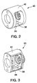
- FIGS 2 and 3 show first and second embodiments, respectively, of the hollow cage or carrier member 20 that is capable of being used in the rotary impact tool 10.
- a channel 38 is located within the internal diameter of the hollow cage or carrier member 20 along one of diametrically spaced longitudinally extending struts 28 and a roller pin or pivot (not shown) is positioned in the channel 38 forming, in effect, a swivel connection.
- FIG. 2 shows the cage or carrier member 20 as a full diameter hollow cage or carrier member 20. This design uses more material, and thus is heavier, than the cage or carrier member 20 shown in Figure 3.
- the additional weight of the cage or carrier member 20 shown in Figure 2 adds to the overall inertia of the rotary impact tool system.
- the result of higher overall inertia of the rotary impact tool system is that more force is provided with each impact of rotary impact tool 10, but the air motor (not shown) speed, and thus the number of impacts per minute, is reduced.
- Figures 4 and 5 show first and second embodiments, respectively, of hollow hammer members 40.
- a roller pin or pivot (not shown) is provided, which is preferably an elongate roller pin, about which a portion of the hollow hammer members 40 can partially rotate.
- the hollow hammer members 40 are mounted around the anvil 24.
- the hammer members 40 are pivotally positioned against the hollow cage or carrier member 20 about a tilt axis formed by the roller pin or pivot (not shown) so the hammer members 40 rotate with the hollow cage or carrier member 20 under drive from the air motor output shaft 14, and additionally, the hammer members 40 can move with an angular pivot motion relative to the cage or carrier member 20 about the tilt axis offset from, but parallel to, the axis of rotation of the cage or carrier member 20.
- the cage or carrier member 20 has a second, diametrically spaced, longitudinally extending, strut 42 within which is formed a second channel (not shown).
- a second roller pin or pivot (not shown) is positioned within the second channel (not shown).
- the hammer members 40 each have a slot 44 formed on their surface which permits the hammer members 40 to rotate through a finite angle with respect to the diametrically spaced longitudinally extending struts 28 and a second diametrically spaced longitudinally extending strut 42, such that the second roller pin or pivot (not shown) will block the hammer members 40 from rotating past the point where edges 46 and 48 of the slot 44 abut the second roller pin or pivot (not shown).
- the hammer members 40 each have on their internal surface 50 a forward impact jaw or surface 52 and a reverse impact jaw or surface 54, which are movable into and out of the path of the forward impact receiving surface 34 and reverse impact receiving surface 36, respectively, as the rotary impact tool 10 operates in the forward or reverse direction.
- the hollow hammer members 40 are preferably shaped in cross-section or symmetrical halves joined along a plane perpendicular to the page and passing through the centre of gravity of the hollow hammer members 40 and the centre of the roller pin or pivot (not shown).
- a rear end portion of the anvil 24 includes an anvil jaw 32 which extends generally radially outwardly therefrom and provides the forward impact receiving surface 34 and reverse impact receiving surface 36.
- the anvil 24 preferably includes an annular ring 56 that is located intermediate a forward anvil lug 58 and a rearward anvil lug 60.
- the addition of the annular ring 56 on the anvil 24 provides additional strength to the unsupported ends of the forward anvil lug 58 and rearward anvil lug 60, which is a common starting point for failures.
- the annular ring 56 can be reduced in size from the diameter of the forward anvil lug 58 and rearward anvil lug 60, as shown in Figures 6 and 7.
- the annular ring 56 can be substantially the same diameter as the forward anvil lug 58 and rearward anvil lug 60, but the sides of the annular ring 56 can be reduced or narrowed to facilitate assembly of the anvil 24 into the hammer members 40, as shown in Figures 8 and 9.
- the sides of annular ring 56 are preferably reduced or narrowed by providing flats on the sides of the annular ring 56, as shown in Figures 8 and 9, although other configurations for providing a reduced or narrowed annular ring 56 could be used.
- Positive spacing of the hollow hammer members 40 can be achieved by placing a spacer 62 between them as shown in Figure 4.
- the spacer 62 precludes the hammer members 40 from contacting the annular ring 56 on the anvil 24.
- the spacer 62 is preferably fabricated from a relatively strong, durable and light-weight material, such as a composite material, which would allow the spacer 62 to be low in relative inertia.
- the spacer 62 is preferably fabricated from a material that reduces sliding friction between the hammer members 40.
- spacer 62 may simplify the design and thus potentially reduce the cost of the hammer members 40, since the hammer members 40 using the spacer 62 have a substantially constant cross-sectional configuration, but the width of each hammer member 40 is reduced to provide space for the spacer 62.
- positive spacing of the hammer members 40 can be achieved by providing steps 64 on the inside face of each hollow hammer member 40 as shown in Figure 5. This permits the hammer members 40 to extend over the annular ring 56 on the anvil 24 with the steps 64 providing clearance for the annular ring 56 on the anvil 24. Thus, the steps 64 on the hammer members 40 preclude the hammer members 40 from contacting the annular ring 56 on the anvil 24. Such a design would eliminate the need for a separate spacer as shown in Figure 4.
- this design allows the width of the hollow hammer members 40 to be maximised at their pivot points where high stresses are experienced during operation of rotary impact tool 10 having a twin hammer mechanism and also allows the weight, and thus the inertia, of the hammer members 40 to be maximised.
- a rotary impact tool that has a twin hammer mechanism which is less susceptible to premature failure and thus provides enhanced durability and service life as compared to known rotary impact tools. Also the twin hammer mechanism is capable of applying the same amount of torque to a workpiece with less air consumption as compared to known rotary impact tools. Also the twin hammer mechanism is capable of applying a greater amount of torque to a workpiece while maintaining the size of the housing as compared to known rotary impact tools.
Landscapes
- Engineering & Computer Science (AREA)
- Mechanical Engineering (AREA)
- Percussive Tools And Related Accessories (AREA)
Abstract
Description
Claims (21)
- A rotary impact tool (10) having a twin hammer mechanism, said rotary impact tool comprising a housing (12), a hollow cage member or carrier member (20) positioned within said housing, a first hollow hammer member (40) and a second hollow hammer member (40) pivotally positioned within said hollow cage member or carrier member (20) so that said first and second hammer members rotate with said cage or carrier member under drive from an air motor output shaft (14) and an anvil (24) positioned inside said first and second hammer members, said anvil being able to rotate relative to said first and second hammer members, and said anvil (24) including a forward anvil lug (58) and a rearward anvil lug (60).
- A tool according to claim 1, wherein an annular ring (56) is positioned intermediate said forward anvil lug (58) and said rearward anvil lug (60).
- A tool according to claim 2, wherein said annular ring (56) has a diameter which is less than the diameter of said forward and rearward anvil lugs (58, 60), respectively, to facilitate the assembly of said anvil (24) within said first and second hammer members (40).
- A tool according to claim 2, wherein said annular ring (56) has a diameter which is substantially the same as the diameter of said forward and rearward anvil lugs (58, 60), respectively and at least a portion of said annular ring is reduced or narrowed to facilitate the assembly of said anvil (24) within said first and second hammer members (40).
- A tool according to claim 2, wherein said annular ring (56) has a diameter which is substantially the same as the diameter of said forward and rearward anvil lugs (58, 60), respectively, and at least a portion of each of the sides of said annular ring are reduced or narrowed to facilitate the assembly of said anvil (24) within said first hammer member and said second hammer members (40).
- A tool according to claim 2, wherein said annular ring (56) has a diameter which is substantially the same as the diameter of said forward and rearward anvil lugs (58, 60), respectively, and a flat is provided on each of the sides of said annular ring to facilitate the assembly of said anvil within said first and second hammer members (40).
- A tool according to any one of claims 2 to 6, further including a spacer (62) positioned between said first and second hammer members (40) to provide positive spacing between said first and second hammer members and preclude said first and second hammer members from contacting said annular ring (56) on said anvil (24).
- A tool according to claim 7, wherein said spacer (62) is fabricated from a relatively strong, durable and light-weight material.
- A tool according to claim 7 or 8, wherein said spacer (62) is fabricated from a material which reduces the sliding friction between said hammer members (40).
- A tool according to claim 7, 8 or 9, wherein said spacer (62) is fabricated from a composite material.
- A tool according to any one of claims 2 to 10, wherein said first and said second hammer members (40) each include a step (64) on an interior face thereof to provide positive spacing between said hammer members and preclude them from contacting said annular ring (56)on said anvil.
- A tool according to any one of the preceding claims, wherein at least a portion of said forward anvil lug (58) overlaps a portion of said rearward anvil lug (60).
- An anvil (24) for a rotary impact tool (10) having a twin hammer mechanism, said anvil comprising a forward anvil lug (58), a rearward anvil lug (60) coaxial with said forward anvil lug and an annular ring (56) positioned intermediate said forward anvil lug and said rearward anvil lug.
- An anvil according to claim 13, wherein said annular ring (56) has a diameter which is less than the diameter of said forward and rearward anvil lugs (58, 60) respectively.
- An anvil according to claim 13, wherein said annular ring (56) has a diameter which is substantially the same as the diameter of said forward and rearward anvil lugs and at least a portion of said annular ring is reduced or narrowed.
- An anvil according to claim 13, wherein said annular ring (56) has a diameter which is substantially the same as the diameter of said forward and rearward anvil lugs and at least a portion of each of the sides of said annular ring are reduced or narrowed.
- An anvil according to claim 13, wherein said annular ring has a diameter which is substantially the same as the diameter of said forward and rearward anvil lugs and a flat is provided on each of the sides of said annular ring.
- An anvil (24) for a rotary impact tool (10) having a twin hammer mechanism, said anvil comprising a forward anvil lug (58) and a rearward anvil lug (60) coaxial with said forward anvil lug and at least a portion of said forward anvil lug overlaps at least a portion of said rearward anvil lug.
- A hollow hammer assembly for a rotary impact tool having a twin hammer mechanism, said hollow hammer assembly comprising a first hollow hammer member (40), a second hollow hammer member (40) positioned coaxial with said first hollow hammer member and a spacer (62) positioned between said first and second hammer members to provide positive spacing between said first and second hollow hammer members.
- A hollow hammer assembly for a rotary impact tool (10) having a twin hammer mechanism, said hollow hammer assembly comprising a first hollow hammer member (40) and a second hollow hammer member (40) positioned coaxial with said first hammer member, each hammer member including a step (64) on an interior face thereof to provide positive spacing between said hammer members.
- A hollow cage or carrier member (20) for a rotary impact tool (10) having a twin hammer mechanism, said hollow cage or carrier member having a substantially full diameter configuration to provide said hollow cage or carrier member with increased weight and thus increase the overall system inertia of the rotary impact tool having a twin hammer mechanism.
Applications Claiming Priority (2)
| Application Number | Priority Date | Filing Date | Title |
|---|---|---|---|
| US09/617,333 US6491111B1 (en) | 2000-07-17 | 2000-07-17 | Rotary impact tool having a twin hammer mechanism |
| US617333 | 2000-07-17 |
Publications (2)
| Publication Number | Publication Date |
|---|---|
| EP1174222A2 true EP1174222A2 (en) | 2002-01-23 |
| EP1174222A3 EP1174222A3 (en) | 2003-01-22 |
Family
ID=24473221
Family Applications (1)
| Application Number | Title | Priority Date | Filing Date |
|---|---|---|---|
| EP01306148A Withdrawn EP1174222A3 (en) | 2000-07-17 | 2001-07-17 | Rotary impact tool having a twin hammer mechanism |
Country Status (5)
| Country | Link |
|---|---|
| US (1) | US6491111B1 (en) |
| EP (1) | EP1174222A3 (en) |
| JP (1) | JP2002113668A (en) |
| CN (1) | CN1334177A (en) |
| HK (1) | HK1043761A1 (en) |
Cited By (5)
| Publication number | Priority date | Publication date | Assignee | Title |
|---|---|---|---|---|
| CN102348537A (en) * | 2009-03-25 | 2012-02-08 | 阿特拉斯·科普柯工具公司 | Pneumatic power wrench with a exhaust air outlet unit |
| EP2799186A1 (en) * | 2013-05-02 | 2014-11-05 | Basso Industry Corp. | Pneumatic ratchet wrench |
| GB2514260A (en) * | 2013-05-17 | 2014-11-19 | Snap On Tools Corp | Impact wrench anvil |
| CN104275668A (en) * | 2013-07-01 | 2015-01-14 | 英古所连公司 | Rotary Impact Tool |
| TWI875430B (en) * | 2024-01-11 | 2025-03-01 | 冠億齒輪股份有限公司 | Pneumatic Tools |
Families Citing this family (54)
| Publication number | Priority date | Publication date | Assignee | Title |
|---|---|---|---|---|
| US6609577B2 (en) * | 2001-09-29 | 2003-08-26 | Bark International, Inc. | Percussive rotational impact hammer |
| US7331404B2 (en) * | 2002-10-10 | 2008-02-19 | Snap-On Incorporated | Lubrication system for impact wrenches |
| US6889778B2 (en) * | 2003-01-31 | 2005-05-10 | Ingersoll-Rand Company | Rotary tool |
| US6863134B2 (en) * | 2003-03-07 | 2005-03-08 | Ingersoll-Rand Company | Rotary tool |
| US6782956B1 (en) | 2003-03-07 | 2004-08-31 | Ingersoll-Rand Company | Drive system having an inertial valve |
| US20050145401A1 (en) * | 2004-01-05 | 2005-07-07 | Hsin-Her Chang | Pneumatic wrench hammer |
| US7165631B2 (en) * | 2004-07-19 | 2007-01-23 | Hsin Ho Chang | Pneumatic wrench having enhanced strength |
| US7182149B2 (en) * | 2004-08-11 | 2007-02-27 | Hsin Ho Chang | Pneumatic wrench having reinforced strength |
| TWM274210U (en) * | 2005-01-18 | 2005-09-01 | Tranmax Machinery Co Ltd | Improved structure of dual-anvil striking set |
| US20060225903A1 (en) * | 2005-04-07 | 2006-10-12 | Sterling Robert E | Rotary impact tool, shock attenuating coupling device for a rotary impact tool, and rotary impact attenuating device |
| US20060237205A1 (en) * | 2005-04-21 | 2006-10-26 | Eastway Fair Company Limited | Mode selector mechanism for an impact driver |
| EP1733849A1 (en) * | 2005-06-15 | 2006-12-20 | Caterpillar, Inc. | Tool assembly having a two part body |
| EP1733851B1 (en) * | 2005-06-15 | 2013-01-02 | Caterpillar Inc. | Tool Retention Apparatus and Method |
| TWI424910B (en) * | 2006-01-27 | 2014-02-01 | Exhaust Technologies Inc | Shock attenuating device for a rotary impact tool |
| US7438140B2 (en) * | 2006-01-27 | 2008-10-21 | Exhaust Technologies, Inc. | Shock attenuating device for a rotary impact tool |
| USD590680S1 (en) | 2006-04-18 | 2009-04-21 | Ingersoll-Rand Company | Air tool |
| USD590682S1 (en) | 2006-04-18 | 2009-04-21 | Ingersoll-Rand Company | Air tool |
| USD591130S1 (en) | 2006-04-18 | 2009-04-28 | Ingersoll-Rand Company | Air tool |
| USD590681S1 (en) | 2006-04-18 | 2009-04-21 | Ingersoll-Rand Company | Air tool |
| DE102006061625A1 (en) * | 2006-12-27 | 2008-07-03 | Robert Bosch Gmbh | Electric hand tool e.g. drill hammer, has motor connectable with spindle and/or sliding tool over transmission and pivotable around axis, where middle axle of shaft of transmission or central axle of drive shaft forms axis |
| US7510023B1 (en) * | 2007-12-21 | 2009-03-31 | Kuani Gear Co., Ltd. | Impact assembly for a power tool |
| CN102083593B (en) * | 2008-05-07 | 2014-07-23 | 密尔沃基电动工具公司 | Drive assembly for a power tool |
| SE532449C2 (en) * | 2008-05-14 | 2010-01-19 | Atlas Copco Tools Ab | Pneumatic pulse nut puller with work control means |
| US8020630B2 (en) * | 2009-05-29 | 2011-09-20 | Ingersoll Rand Company | Swinging weight assembly for impact tool |
| JP4457170B1 (en) * | 2009-06-03 | 2010-04-28 | 株式会社空研 | Impact wrench |
| CN201437237U (en) * | 2009-07-10 | 2010-04-14 | 海峰机械工业股份有限公司 | Rotary impact tool head |
| USD616717S1 (en) | 2009-08-26 | 2010-06-01 | Ingersoll-Rand Company | Impact wrench |
| WO2012061176A2 (en) | 2010-11-04 | 2012-05-10 | Milwaukee Electric Tool Corporation | Impact tool with adjustable clutch |
| US9592600B2 (en) | 2011-02-23 | 2017-03-14 | Ingersoll-Rand Company | Angle impact tools |
| US8925646B2 (en) | 2011-02-23 | 2015-01-06 | Ingersoll-Rand Company | Right angle impact tool |
| DE102011005079A1 (en) * | 2011-03-04 | 2012-09-06 | Hilti Aktiengesellschaft | Setting method for an expansion anchor and impact wrench for setting a spreading anchor |
| US9272400B2 (en) | 2012-12-12 | 2016-03-01 | Ingersoll-Rand Company | Torque-limited impact tool |
| US9022888B2 (en) | 2013-03-12 | 2015-05-05 | Ingersoll-Rand Company | Angle impact tool |
| US9707669B2 (en) | 2013-04-24 | 2017-07-18 | Shining Golden Yida Welding & Cutting Machinery Manufacture, Ltd. | Motors with magnetic components |
| TW201406501A (en) * | 2013-10-31 | 2014-02-16 | Quan-Zheng He | Impact set of pneumatic tool |
| TW201520006A (en) * | 2013-11-20 | 2015-06-01 | Kuani Gear Co Ltd | Power driving tool having unicorn type impact set |
| TW201520007A (en) * | 2013-11-20 | 2015-06-01 | Kuani Gear Co Ltd | Power drive tool equipped with strike disc type impact assembly |
| US20150165603A1 (en) * | 2013-12-17 | 2015-06-18 | Ming-Ta Cheng | Power device with a unicorn impact unit |
| US9539715B2 (en) * | 2014-01-16 | 2017-01-10 | Ingersoll-Rand Company | Controlled pivot impact tools |
| US20150202750A1 (en) * | 2014-01-22 | 2015-07-23 | Sp Air Kabushiki Kaisha | Twin hammer clutch impact wrench |
| US9737978B2 (en) | 2014-02-14 | 2017-08-22 | Ingersoll-Rand Company | Impact tools with torque-limited swinging weight impact mechanisms |
| TWI469853B (en) * | 2014-05-23 | 2015-01-21 | Soartec Ind Corp | Hammering set for a impact tool |
| US20150343616A1 (en) * | 2014-06-03 | 2015-12-03 | Soartec Industrial Corp. | Hammering set for an impact tool |
| US10471573B2 (en) | 2016-01-05 | 2019-11-12 | Milwaukee Electric Tool Corporation | Impact tool |
| JP6832509B2 (en) * | 2017-03-27 | 2021-02-24 | パナソニックIpマネジメント株式会社 | Rotary striking tool |
| AU2019221782A1 (en) * | 2018-02-19 | 2020-10-08 | Milwaukee Electric Tool Corporation | Impact tool |
| US11247321B2 (en) * | 2018-04-20 | 2022-02-15 | Ingersoll-Rand Industrial U.S., Inc. | Impact tools with rigidly coupled impact mechanisms |
| CN110587551A (en) | 2018-06-12 | 2019-12-20 | 筌诚机械股份有限公司 | Impact block for power tool impact assembly and retainer cooperating therewith |
| CN110587550A (en) | 2018-06-12 | 2019-12-20 | 筌诚机械股份有限公司 | Impact block for power tool impact assembly and retainer cooperating therewith |
| EP3898101A4 (en) * | 2018-12-21 | 2022-11-30 | Milwaukee Electric Tool Corporation | HIGH TORQUE IMPACT TOOL |
| CN211805940U (en) | 2019-09-20 | 2020-10-30 | 米沃奇电动工具公司 | Impact tool and hammer head |
| CN112757206A (en) * | 2021-01-06 | 2021-05-07 | 四川九洲电器集团有限责任公司 | Impact-resistant automatic tightening wrench and self-tightening method thereof |
| WO2024059488A2 (en) | 2022-09-13 | 2024-03-21 | Black & Decker Inc. | Electrostatic clutch for power tool |
| US12528170B2 (en) | 2023-04-25 | 2026-01-20 | Milwaukee Electric Tool Corporation | Impact tool anvil with improved durability |
Family Cites Families (50)
| Publication number | Priority date | Publication date | Assignee | Title |
|---|---|---|---|---|
| US2285638A (en) | 1939-11-22 | 1942-06-09 | Chicago Pneumatic Tool Co | Impact clutch |
| US2580631A (en) | 1946-05-02 | 1952-01-01 | Reed Roller Bit Co | Impact tool |
| US2663395A (en) | 1951-10-16 | 1953-12-22 | Reed Roller Bit Co | Impact hammer element |
| US2802556A (en) | 1952-05-14 | 1957-08-13 | Reed Roller Bit Co | Impact hammer element |
| US3072232A (en) | 1960-12-02 | 1963-01-08 | Airetool Mfg Company | Rotary impact tool |
| US3321043A (en) | 1964-03-24 | 1967-05-23 | Ingersoll Rand Co | Oil bath lubrication for mechanism |
| US3389756A (en) | 1965-08-09 | 1968-06-25 | Kawamoto Mitsugi | Impact wrench |
| US3414066A (en) | 1966-08-31 | 1968-12-03 | Chicago Pneumatic Tool Co | Impact wrench |
| US3428137A (en) | 1967-10-12 | 1969-02-18 | Chicago Pneumatic Tool Co | Impact wrench |
| US3605914A (en) | 1968-08-23 | 1971-09-20 | Ingersoll Rand Co | Rotary impact wrench mechanism |
| US3552499A (en) | 1968-10-10 | 1971-01-05 | Spencer B Maurer | Rotary power tool clutch mechanism |
| US3533479A (en) | 1968-10-23 | 1970-10-13 | Sioux Tools Inc | Impact mechanism with improved hammer and hammer frame assembly therefor |
| JPS4831599B1 (en) | 1969-07-30 | 1973-09-29 | ||
| US3661217A (en) | 1970-07-07 | 1972-05-09 | Spencer B Maurer | Rotary impact tool and clutch therefor |
| US4042036A (en) | 1973-10-04 | 1977-08-16 | Smith James E | Electric impact tool |
| SE391143B (en) | 1974-10-02 | 1977-02-07 | Atlas Copco Ab | ROTATION BATCH COUPLING |
| US4016940A (en) | 1975-10-21 | 1977-04-12 | Chicago Pneumatic Tool Company | Pneumatic nut runner having a directional valve and an air regulator |
| USD248820S (en) | 1977-02-17 | 1978-08-08 | Chicago Pneumatic Tool Company | Impact wrench |
| USD256980S (en) | 1977-12-22 | 1980-09-23 | Snap-On Tools Corporation | Impact wrench |
| US4321973A (en) | 1979-08-10 | 1982-03-30 | Maurer Spencer B | Rotary impact clutch |
| US4287956A (en) | 1979-08-10 | 1981-09-08 | Maurer Spencer B | Impact wrench mechanism and pivot clutch |
| US4347902A (en) | 1979-12-18 | 1982-09-07 | Chicago Pneumatic Tool Company | Rotary impact wrench clutch |
| DE3205141A1 (en) | 1982-02-13 | 1983-08-18 | Robert Bosch Gmbh, 7000 Stuttgart | DRILLING HAMMER |
| US4585078A (en) | 1982-09-09 | 1986-04-29 | Alexandrov Vladimir M | Rotary impact tool |
| SE446070B (en) | 1984-12-21 | 1986-08-11 | Atlas Copco Ab | HYDRAULIC TORQUE PULSE FOR TORQUE STRANDING TOOLS |
| USD288770S (en) | 1984-12-24 | 1987-03-17 | Snap-On Tools Corporation | Impact wrench |
| USD288769S (en) | 1984-12-24 | 1987-03-17 | Snap-On Tools Corporation | Impact wrench |
| USD298301S (en) | 1985-08-27 | 1988-11-01 | Snap-On Tools Corporation | Palm grip impact wrench |
| USD324802S (en) | 1989-07-25 | 1992-03-24 | Snap-On Tools Corporation | Impact wrench |
| USD324801S (en) | 1989-07-25 | 1992-03-24 | Snap-On Tools Corporation | Angle head impact wrench |
| US5083619A (en) | 1989-09-25 | 1992-01-28 | Chicago Pneumatic Tool Company | Powered impact wrench |
| US5092410A (en) | 1990-03-29 | 1992-03-03 | Chicago Pneumatic Tool Company | Adjustable pressure dual piston impulse clutch |
| US4977966A (en) | 1990-03-30 | 1990-12-18 | The United States Of America As Represented By The Secretary Of The Navy | Seawater hydraulic rotary impact tool |
| USD335073S (en) | 1991-04-15 | 1993-04-27 | Snap-On Tools Corporation | Cordless impact wrench |
| US5199505A (en) | 1991-04-24 | 1993-04-06 | Shinano Pneumatic Industries, Inc. | Rotary impact tool |
| US5346022A (en) | 1993-01-29 | 1994-09-13 | Snap-On Incorporated | Torque limiting device for air impact tool |
| US5595251A (en) | 1994-08-10 | 1997-01-21 | The United States Of America As Represented By The Administrator Of The National Aeronautics And Space Administration | Displaceable gear torque controlled driver |
| US5622230A (en) | 1995-06-15 | 1997-04-22 | Chicago Pneumatic Tool Company | Rotary impact wrench clutch improvement |
| US5738177A (en) | 1995-07-28 | 1998-04-14 | Black & Decker Inc. | Production assembly tool |
| US5836403A (en) | 1996-10-31 | 1998-11-17 | Snap-On Technologies, Inc. | Reversible high impact mechanism |
| US5908076A (en) * | 1997-01-10 | 1999-06-01 | Power Tool Holders Incorporated | Impact tool driver |
| US5784934A (en) | 1997-01-30 | 1998-07-28 | Shinano Pneumatic Industries, Inc. | Ratchet wrench with pivotable head |
| US6003618A (en) | 1997-07-29 | 1999-12-21 | Chicago Pneumatic Tool Company | Twin lobe impact mechanism |
| US5906244A (en) | 1997-10-02 | 1999-05-25 | Ingersoll-Rand Company | Rotary impact tool with involute profile hammer |
| USD404276S (en) | 1998-01-28 | 1999-01-19 | Snap-On Tools Company | Cordless impact wrench |
| US6024180A (en) | 1998-02-12 | 2000-02-15 | Lin; Chen-Yang | Cage device for a pneumatically driven power tool |
| US6070674A (en) | 1998-06-11 | 2000-06-06 | Chicago Pneumatic Tool Company | Modified cage member for an impact mechanism |
| USD410830S (en) | 1998-07-31 | 1999-06-08 | Snap-On Tools Company | Impact wrench |
| US5941319A (en) * | 1998-10-27 | 1999-08-24 | Juan; Chih-Chen | Electric wrench driving system |
| US5992539A (en) * | 1999-03-16 | 1999-11-30 | Lin; Chen-Yang | Pneumatically driven power tool |
-
2000
- 2000-07-17 US US09/617,333 patent/US6491111B1/en not_active Expired - Lifetime
-
2001
- 2001-07-17 EP EP01306148A patent/EP1174222A3/en not_active Withdrawn
- 2001-07-17 CN CN01125946A patent/CN1334177A/en active Pending
- 2001-07-17 JP JP2001216061A patent/JP2002113668A/en active Pending
-
2002
- 2002-07-22 HK HK02105409.2A patent/HK1043761A1/en unknown
Cited By (11)
| Publication number | Priority date | Publication date | Assignee | Title |
|---|---|---|---|---|
| CN102348537A (en) * | 2009-03-25 | 2012-02-08 | 阿特拉斯·科普柯工具公司 | Pneumatic power wrench with a exhaust air outlet unit |
| CN102348537B (en) * | 2009-03-25 | 2014-06-04 | 阿特拉斯·科普柯工业技术公司 | Pneumatic power wrench with a exhaust air outlet unit |
| EP2799186A1 (en) * | 2013-05-02 | 2014-11-05 | Basso Industry Corp. | Pneumatic ratchet wrench |
| GB2514260A (en) * | 2013-05-17 | 2014-11-19 | Snap On Tools Corp | Impact wrench anvil |
| AU2014202426B2 (en) * | 2013-05-17 | 2016-01-07 | Snap-On Incorporated | Impact wrench anvil |
| GB2514260B (en) * | 2013-05-17 | 2016-03-02 | Snap On Tools Corp | Impact wrench anvil |
| US9393677B2 (en) | 2013-05-17 | 2016-07-19 | Snap-On Incorporated | Impact wrench anvil |
| CN104275668A (en) * | 2013-07-01 | 2015-01-14 | 英古所连公司 | Rotary Impact Tool |
| CN104275668B (en) * | 2013-07-01 | 2016-08-24 | 英古所连公司 | Rotary impact tool |
| US9555532B2 (en) | 2013-07-01 | 2017-01-31 | Ingersoll-Rand Company | Rotary impact tool |
| TWI875430B (en) * | 2024-01-11 | 2025-03-01 | 冠億齒輪股份有限公司 | Pneumatic Tools |
Also Published As
| Publication number | Publication date |
|---|---|
| US6491111B1 (en) | 2002-12-10 |
| HK1043761A1 (en) | 2002-09-27 |
| EP1174222A3 (en) | 2003-01-22 |
| CN1334177A (en) | 2002-02-06 |
| JP2002113668A (en) | 2002-04-16 |
Similar Documents
| Publication | Publication Date | Title |
|---|---|---|
| US6491111B1 (en) | Rotary impact tool having a twin hammer mechanism | |
| EP0941153B1 (en) | Rotary impact tool with involute profile hammer | |
| US6070674A (en) | Modified cage member for an impact mechanism | |
| US3605914A (en) | Rotary impact wrench mechanism | |
| US4826090A (en) | Hammer assembly for a rotary material crusher | |
| EP1473120B1 (en) | Rotary tool | |
| US4034574A (en) | Universal ball and socket swivel joint | |
| US5740892A (en) | Power wrench torque transmission mechanism | |
| CA2723384C (en) | Drive assembly for a power tool | |
| US9415489B2 (en) | Impact mechanism for an electric tool | |
| CN101422889A (en) | Fluid operated torque wrench and method for tightening or loosening fasteners | |
| US4557337A (en) | Impact wrench | |
| WO2010138285A2 (en) | Swinging weight assembly for impact tool | |
| EP2168725A1 (en) | Rotary impact tool | |
| US3848680A (en) | Impact clutch mechanism | |
| US3557884A (en) | Impact wrench mechanism | |
| CN1318184C (en) | Power impact tool torque apparatus | |
| JPH0151309B2 (en) | ||
| IE851420L (en) | Coupling for drilling shank | |
| JPH06190741A (en) | Impact wrench | |
| US3380539A (en) | Impact clutch | |
| EP0149874B1 (en) | An impact wrench | |
| US20250001572A1 (en) | Drive assembly for a power tool | |
| SU903100A1 (en) | Percussion-type power nut-driver | |
| RU2200817C2 (en) | Percussive-indexing mechanism |
Legal Events
| Date | Code | Title | Description |
|---|---|---|---|
| PUAI | Public reference made under article 153(3) epc to a published international application that has entered the european phase |
Free format text: ORIGINAL CODE: 0009012 |
|
| AK | Designated contracting states |
Kind code of ref document: A2 Designated state(s): AT BE CH CY DE DK ES FI FR GB GR IE IT LI LU MC NL PT SE TR |
|
| AX | Request for extension of the european patent |
Free format text: AL;LT;LV;MK;RO;SI |
|
| PUAL | Search report despatched |
Free format text: ORIGINAL CODE: 0009013 |
|
| AK | Designated contracting states |
Kind code of ref document: A3 Designated state(s): AT BE CH CY DE DK ES FI FR GB GR IE IT LI LU MC NL PT SE TR |
|
| AX | Request for extension of the european patent |
Free format text: AL;LT;LV;MK;RO;SI |
|
| 17P | Request for examination filed |
Effective date: 20030711 |
|
| AKX | Designation fees paid |
Designated state(s): DE FR GB SE |
|
| 17Q | First examination report despatched |
Effective date: 20070112 |
|
| STAA | Information on the status of an ep patent application or granted ep patent |
Free format text: STATUS: THE APPLICATION IS DEEMED TO BE WITHDRAWN |
|
| 18D | Application deemed to be withdrawn |
Effective date: 20070724 |