EP1174217A1 - Method for enhancing fatigue strength of gear using shotpeening - Google Patents
Method for enhancing fatigue strength of gear using shotpeening Download PDFInfo
- Publication number
- EP1174217A1 EP1174217A1 EP01109691A EP01109691A EP1174217A1 EP 1174217 A1 EP1174217 A1 EP 1174217A1 EP 01109691 A EP01109691 A EP 01109691A EP 01109691 A EP01109691 A EP 01109691A EP 1174217 A1 EP1174217 A1 EP 1174217A1
- Authority
- EP
- European Patent Office
- Prior art keywords
- gear
- tooth
- peening
- shot
- shot balls
- Prior art date
- Legal status (The legal status is an assumption and is not a legal conclusion. Google has not performed a legal analysis and makes no representation as to the accuracy of the status listed.)
- Withdrawn
Links
Images

Classifications
-
- B—PERFORMING OPERATIONS; TRANSPORTING
- B24—GRINDING; POLISHING
- B24C—ABRASIVE OR RELATED BLASTING WITH PARTICULATE MATERIAL
- B24C1/00—Methods for use of abrasive blasting for producing particular effects; Use of auxiliary equipment in connection with such methods
- B24C1/10—Methods for use of abrasive blasting for producing particular effects; Use of auxiliary equipment in connection with such methods for compacting surfaces, e.g. shot-peening
Definitions
- the present invention relates to a method for enhancing fatigue strength of a gear by using shot peening to produce compressive residual stress on a gear surface.
- the shot peening is a method for enhancing strength of manufactures by projecting a plurality of shot balls at a high speed onto surfaces of the manufactures to leave compressive residual stress on the surfaces.
- An impeller or an air nozzle is used for projecting the shot balls, between which the air nozzle grows to be more and more used in the shot ball-projecting technology.
- FIG. 1 shows a schematic illustration of a shot peening method using an air nozzle to project shot balls.
- a high-pressure air supply pipe 3 and a shot ball supply pipe 4 are connected to the air nozzle 2, and the air nozzle 2 faces a gear 1. Shot balls are supplied to the air nozzle 2 via the shot ball supply pipe 4 and are projected at a high speed onto a surface of the gear 1 by means of kinetic energy of high-pressure air injected through the air nozzle 2.
- the shot balls is projected from the air nozzle 2 toward a center of the gear 1.
- the shot balls are projected in a direction orthogonal to a tangent line of a gear circle such as a root circle or a pitch circle. Consequently, the compressive residual stress produced on a side surface of the gear tooth sloping to the direction of projection is weaker than that produced on a tooth face or a tooth flank.
- impact energy E 1 applied upon collision of the shot balls against the tooth face or the tooth has a magnitude of 1/2 ⁇ mv 2 because the shot balls are projected in the orthogonal direction to the tooth face or the tooth flank
- impact energy Eg applied upon collision of the shot balls against the side surface of the gear tooth has a magnitude of 1/2 ⁇ mv 2 ⁇ sin ⁇ because the shot balls are projected onto the side surface inclined to the tooth face or the tooth flank at an angle of inclination ( ⁇ ).
- the protrusions must be removed using a semi-topping or a grinding process followed by the shot peening process during manufacture of the gear. This means that additional equipments and workers are required for removing the protrusion, which causes increase of production cost and lowering in productivity.
- the present invention has been made to overcome the above-mentioned problems, and it is an object of the present invention to provide a method for enhancing fatigue strength of a gear using shot peening, in which magnitude of compressive residual stress produced on a side surface of a gear tooth is larger at least than that produced on a tooth face so that formation of protrusions at outer edges of the gear tooth can be prevented and process time required for the shot peening can be shortened.
- a method for enhancing fatigue strength of a gear using shot peening in accordance with the present invention, in which: a plurality of shot balls are projected onto a gear surface in a direction parallel to a straight line connecting a contact point of a root circle and an involute curve of a gear tooth to be subjected to the peening to a contact point of a tooth face circle and an involute curve of a gear tooth adjacent to the gear tooth to be subjected to the peening by use of high-pressure air.
- the direction of projection of the shot balls forms an angle of 0° to 15° relative to the straight line connecting the contact point of the root circle and the involute curve of the gear tooth to be subjected to peening to the contact point of the tooth face circle and the involute curve of the gear tooth adjacent to the gear tooth to be subjected to the peening.
- the present inventors have conducted a series of experiments for finding out relationship between an angle at which shot balls are projected onto a working surface during the shot peening and compressive residual stress produced on the working surface.
- the experiments are performed in such a manner that the shot balls (round cut wire type, 0.6 mm in diameter, HRC 58 ⁇ 62) are projected onto a flat carburizing steel plate (texture composition: martensite 80 %, austenite 20 %) at different angles of projection and then magnitude and depth of the compressive residual stress produced on a surface of the steel plate are measured for each angle. Results of the experiments are shown in the following Table. Angle of projection of shot balls 90° 80° 70° 60° 50° Maximum compressive residual stress (kg/mm 2 ) 135 130 111 105 101 Depth of compressive residual stress produced ( ⁇ m) 120 95 88 78 75
- the shot balls are projected during the shot peening process in a direction making an angle ⁇ at which the shot balls are projected onto a side surface of a gear tooth, that is, a portion to be subjected to large force when the gear is in operation be larger than an angle ⁇ at which the shot balls are projected onto a tooth face or a tooth flank, that is, a portion to be subjected to relatively small force as shown in FIG. 3.
- magnitude of the compressive residual stress produced on the side surface of the gear tooth becomes similar to or larger than that produced on the tooth face. Accordingly, it is possible to prevent deformation of outer edges of the gear tooth and thus formation of protrusions at outer edges of the gear tooth.
- a deddendum point B2 it is required to increase fatigue strength of a portion of the side surface of the gear tooth to which the largest force is applied when the gear is in operation, that is, a deddendum point B2.
- optimal direction of projection is theoretically said to be a direction parallel to a straight line connecting a contact point B2 of a root circle and an involute curve of a gear tooth to be subjected to the peening to a contact point B1 of a tooth face circle and an involute curve of a gear tooth adjacent to the gear tooth to be subjected to the peening as shown in FIG. 4. If the shot balls are projected in this direction, the fatigue strength of the portion of the gear tooth to which the largest force is applied can become the largest.
- the magnitude of the compressive residual stress produced on the side surface of the gear tooth comes to be similar to or larger than that produced on the tooth face. Accordingly, the formation of the protrusions at outer edges of the gear tooth as in the conventional method can be prevented, and so the semi-topping or grinding process for removing the protrusions does not have to be performed.
- the necessary time to obtain the fatigue strength required for the side surface of the gear tooth can be shortened because the magnitude of the compressive residual stress produced on the side surface of the gear tooth, in particular, the deddendum point B2 is maximized by projecting the shot balls in the above-mentioned direction.
Landscapes
- Engineering & Computer Science (AREA)
- Mechanical Engineering (AREA)
- Gears, Cams (AREA)
- Heat Treatment Of Articles (AREA)
Abstract
Disclosed is a method for enhancing fatigue strength of a
gear by producing compressive residual stress on a gear surface
using shot peening. In the method according to the present
invention, a plurality of shot balls are projected in a
direction parallel to a straight line connecting a contact
point of a root circle and an involute curve of a gear tooth to
be subjected to the peening to a contact point of a tooth face
circle and an involute curve of a gear tooth adjacent to the
gear tooth to be subjected to the peening, and particularly a
direction forming an angle of 0° to 15° relative to the
straight line by use of high-pressure air.
Description
- The present invention relates to a method for enhancing fatigue strength of a gear by using shot peening to produce compressive residual stress on a gear surface.
- In accordance with development of technologies, higher strength is required for mechanical components used in automobiles or industrial apparatuses. To satisfy this, various method for enhancing the strength of the mechanical components have been proposed. In a case of a gear, one of basic mechanical components, shot peening is mainly utilized in order to enhance its strength.
- The shot peening is a method for enhancing strength of manufactures by projecting a plurality of shot balls at a high speed onto surfaces of the manufactures to leave compressive residual stress on the surfaces. An impeller or an air nozzle is used for projecting the shot balls, between which the air nozzle grows to be more and more used in the shot ball-projecting technology.
- FIG. 1 shows a schematic illustration of a shot peening method using an air nozzle to project shot balls.
- As shown in the drawing, a high-pressure air supply pipe 3 and a shot
ball supply pipe 4 are connected to theair nozzle 2, and theair nozzle 2 faces agear 1. Shot balls are supplied to theair nozzle 2 via the shotball supply pipe 4 and are projected at a high speed onto a surface of thegear 1 by means of kinetic energy of high-pressure air injected through theair nozzle 2. - By colliding the shot balls at a high speed against the surface of the
gear 1, compressive residual stress on the gear surface is getting larger by impact due to the collision. As a result of this, strength of thegear 1 is enhanced, and particularly strength of a root portion of tooth to which force is applied upon operation of thegear 1 is greatly increased, thereby making it possible to prevent breakage of thegear 1. - In such a conventional method for enhancing strength of the
gear 1 using the shot peening, the shot balls is projected from theair nozzle 2 toward a center of thegear 1. In other words, the shot balls are projected in a direction orthogonal to a tangent line of a gear circle such as a root circle or a pitch circle. Consequently, the compressive residual stress produced on a side surface of the gear tooth sloping to the direction of projection is weaker than that produced on a tooth face or a tooth flank. - As shown in FIG. 2, that is, whereas impact energy E1 applied upon collision of the shot balls against the tooth face or the tooth has a magnitude of 1/2·mv2 because the shot balls are projected in the orthogonal direction to the tooth face or the tooth flank, impact energy Eg applied upon collision of the shot balls against the side surface of the gear tooth has a magnitude of 1/2 · mv2·sin because the shot balls are projected onto the side surface inclined to the tooth face or the tooth flank at an angle of inclination (). By this reason, the compressive residual stress produced on the side surface of the gear tooth is weaker than that produced on the tooth face or the tooth flank. Due to deformation caused by this difference in the compressive residual stress, protrusions are formed at both ends of the tooth faces, i.e., outer edges of the gear tooth.
- Since such protrusions formed on the outer edges of the gear tooth repeatedly interferes with and impacts on the tooth face of the gear during operation of the gear, there is a problem in that the tooth face of the gear is broken down and thus life span of the gear is shortened.
- To prevent this, the protrusions must be removed using a semi-topping or a grinding process followed by the shot peening process during manufacture of the gear. This means that additional equipments and workers are required for removing the protrusion, which causes increase of production cost and lowering in productivity.
- On the other hand, force is most applied to the side surface of the gear tooth when the gear is in operation. Nevertheless, because magnitude of the compressive residual stress produced on the side surface of the gear tooth is smaller than that produced on the tooth face to which force is less applied than to the side surface, process time required for the shot peening must be extended so as to impart necessary level of strength to the side surface of the gear. Accordingly, there is another problem in that working hours and quantity of consumption of the shot balls are increased and life span of the peening device is shortened.
- Accordingly, the present invention has been made to overcome the above-mentioned problems, and it is an object of the present invention to provide a method for enhancing fatigue strength of a gear using shot peening, in which magnitude of compressive residual stress produced on a side surface of a gear tooth is larger at least than that produced on a tooth face so that formation of protrusions at outer edges of the gear tooth can be prevented and process time required for the shot peening can be shortened.
- To achieve this object, there is provided a method for enhancing fatigue strength of a gear using shot peening in accordance with the present invention, in which:
a plurality of shot balls are projected onto a gear surface in a direction parallel to a straight line connecting a contact point of a root circle and an involute curve of a gear tooth to be subjected to the peening to a contact point of a tooth face circle and an involute curve of a gear tooth adjacent to the gear tooth to be subjected to the peening by use of high-pressure air. - Preferably, the direction of projection of the shot balls forms an angle of 0° to 15° relative to the straight line connecting the contact point of the root circle and the involute curve of the gear tooth to be subjected to peening to the contact point of the tooth face circle and the involute curve of the gear tooth adjacent to the gear tooth to be subjected to the peening.
- The above objects, and other features and advantages of the present invention will become more apparent from the following detailed description in conjunction with the drawings, in which:
- FIG. 1 is a schematic view illustrating a conventional method for enhancing fatigue strength of a gear using air nozzle-shot peening;
- FIG. 2 is a view showing a direction of projection of shot balls in the conventional method;
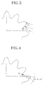
- FIGs. 3 and 4 are views for explaining processes of setting the direction of projection of the shot balls in a method for enhancing fatigue strength of a gear using shot peening according to the present invention, respectively.
-
- Hereinafter, a preferred embodiment of method for enhancing fatigue strength of a gear using shot peening according to the present invention will be described with reference to the accompanying drawings.
- The present inventors have conducted a series of experiments for finding out relationship between an angle at which shot balls are projected onto a working surface during the shot peening and compressive residual stress produced on the working surface. The experiments are performed in such a manner that the shot balls (round cut wire type, 0.6 mm in diameter, HRC 58∼62) are projected onto a flat carburizing steel plate (texture composition: martensite 80 %, austenite 20 %) at different angles of projection and then magnitude and depth of the compressive residual stress produced on a surface of the steel plate are measured for each angle. Results of the experiments are shown in the following Table.
Angle of projection of shot balls 90° 80° 70° 60° 50° Maximum compressive residual stress (kg/mm2) 135 130 111 105 101 Depth of compressive residual stress produced (µm) 120 95 88 78 75 - It can be seen from the Table that magnitude and depth of the compressive residual stress produced on the working surface is the largest when the shot balls are projected in a direction orthogonal to the working surface, and decreases more and more as the angle of projection grows smaller. This can be also theoretically proved from the equation of kinetic energy, 1/2 · mv2 · sin.
- On the basis of the above results, in the inventive method for enhancing fatigue strength of a gear using shot peening, the shot balls are projected during the shot peening process in a direction making an angle β at which the shot balls are projected onto a side surface of a gear tooth, that is, a portion to be subjected to large force when the gear is in operation be larger than an angle α at which the shot balls are projected onto a tooth face or a tooth flank, that is, a portion to be subjected to relatively small force as shown in FIG. 3.
- As a consequence of this, magnitude of the compressive residual stress produced on the side surface of the gear tooth becomes similar to or larger than that produced on the tooth face. Accordingly, it is possible to prevent deformation of outer edges of the gear tooth and thus formation of protrusions at outer edges of the gear tooth.
- From another point of view, it is required to increase fatigue strength of a portion of the side surface of the gear tooth to which the largest force is applied when the gear is in operation, that is, a deddendum point B2. Taking consideration into this, optimal direction of projection is theoretically said to be a direction parallel to a straight line connecting a contact point B2 of a root circle and an involute curve of a gear tooth to be subjected to the peening to a contact point B1 of a tooth face circle and an involute curve of a gear tooth adjacent to the gear tooth to be subjected to the peening as shown in FIG. 4. If the shot balls are projected in this direction, the fatigue strength of the portion of the gear tooth to which the largest force is applied can become the largest.
- In practice, however, there may occur a phenomenon that a part of the projected shot balls change their moving direction due to colliding against the point B2 and so interrupt a path of the shot balls moving toward the point B2. In order to prevent this phenomenon, the shot balls must be projected in a direction in which bad influence on the path of the shot balls projected toward the point B2 can be minimized.
- Although such a direction is determined by various factors such as size and hardness of the shot balls, projection speed, shape of the manufacture and so on, several experiments have exhibit that the compressive residual stress produced at the deddendum point B2 to which the largest force is applied has a maximal magnitude in most manufacturing specifications of the shot ball and the gear when the shot balls are projected in a direction forming an angle of 0° to 15° relative to the straight line connecting the point B2 to the point B1.
- In the end, by projecting the shot balls in the direction forming an angle of 0° to 15° relative to the straight line connecting the point B2 to the point B1, the magnitude of the compressive residual stress produced on the side surface of the gear tooth comes to be similar to or larger than that produced on the tooth face. Accordingly, the formation of the protrusions at outer edges of the gear tooth as in the conventional method can be prevented, and so the semi-topping or grinding process for removing the protrusions does not have to be performed.
- Moreover, the necessary time to obtain the fatigue strength required for the side surface of the gear tooth can be shortened because the magnitude of the compressive residual stress produced on the side surface of the gear tooth, in particular, the deddendum point B2 is maximized by projecting the shot balls in the above-mentioned direction.
- While the present invention has been illustrated and described under considering a preferred specific embodiment thereof, it will be easily understood by those skilled in the art that the present invention is not limited to the specific embodiment, and various changes, modifications and equivalents may be made without departing from the true scope of the present invention.
Claims (2)
- A method for enhancing fatigue strength of a gear using shot peening which produces compressive residual stress on a gear surface by projecting a plurality of shot balls onto the gear surface by use of high-pressure air, in which:
the plurality of shot balls are projected in a direction parallel to a straight line connecting a contact point of a root circle and an involute curve of a gear tooth to be subjected to the peening to a contact point of a tooth face circle and an involute curve of a gear tooth adjacent to the gear tooth to be subjected to the peening. - A method as recited in claim 1, wherein the direction of projection of the shot balls forms an angle of 0° to 15° relative to the straight line.
Applications Claiming Priority (2)
| Application Number | Priority Date | Filing Date | Title |
|---|---|---|---|
| KR2000041104 | 2000-07-18 | ||
| KR10-2000-0041104A KR100373280B1 (en) | 2000-07-18 | 2000-07-18 | a gear processing method using air nozzle shot peening |
Publications (1)
| Publication Number | Publication Date |
|---|---|
| EP1174217A1 true EP1174217A1 (en) | 2002-01-23 |
Family
ID=19678546
Family Applications (1)
| Application Number | Title | Priority Date | Filing Date |
|---|---|---|---|
| EP01109691A Withdrawn EP1174217A1 (en) | 2000-07-18 | 2001-04-19 | Method for enhancing fatigue strength of gear using shotpeening |
Country Status (5)
| Country | Link |
|---|---|
| US (1) | US20020029597A1 (en) |
| EP (1) | EP1174217A1 (en) |
| JP (1) | JP2002039328A (en) |
| KR (1) | KR100373280B1 (en) |
| CN (1) | CN1334346A (en) |
Cited By (1)
| Publication number | Priority date | Publication date | Assignee | Title |
|---|---|---|---|---|
| WO2005068666A1 (en) * | 2004-01-15 | 2005-07-28 | Siemens Aktiengesellschaft | Component with internal compressive stress, method for producing said component and device for generating internal compressive stress |
Families Citing this family (16)
| Publication number | Priority date | Publication date | Assignee | Title |
|---|---|---|---|---|
| JP2003088935A (en) * | 2001-09-13 | 2003-03-25 | Sumitomo Heavy Ind Ltd | Manufacturing method of external gear |
| JP4812220B2 (en) * | 2002-05-10 | 2011-11-09 | 株式会社小松製作所 | High hardness and toughness steel |
| JP2004076125A (en) * | 2002-08-21 | 2004-03-11 | Komatsu Ltd | Rolling member |
| KR100465509B1 (en) * | 2002-11-26 | 2005-01-13 | 임성혁 | Impeller type of shot peening equipment having air conditioner |
| JP4390576B2 (en) * | 2003-03-04 | 2009-12-24 | 株式会社小松製作所 | Rolling member |
| JP4390526B2 (en) * | 2003-03-11 | 2009-12-24 | 株式会社小松製作所 | Rolling member and manufacturing method thereof |
| JP5298958B2 (en) * | 2009-03-03 | 2013-09-25 | 日産自動車株式会社 | Shot peening processing method, hypoid gear using the processing method, and shot peening processing apparatus |
| JP6213867B2 (en) * | 2013-02-21 | 2017-10-18 | 住友電工ハードメタル株式会社 | Surface-coated cutting tool and manufacturing method thereof |
| CN104451079B (en) * | 2014-12-11 | 2016-07-06 | 南车戚墅堰机车车辆工艺研究所有限公司 | A kind of gear teeth face shot peening strengthening finely finishing method |
| CN104625967A (en) * | 2014-12-24 | 2015-05-20 | 上海振华重工集团(南通)传动机械有限公司 | Shot blasting treatment method for increasing stress of gear workpiece |
| JP6706929B2 (en) | 2016-02-22 | 2020-06-10 | 三菱航空機株式会社 | How to improve fatigue strength |
| DE102016012941B4 (en) * | 2016-10-28 | 2019-06-06 | Mvo Gmbh Metallverarbeitung Ostalb | Process for machining a toothed rack and subsequently machined rack |
| CN108318244B (en) * | 2018-01-23 | 2019-12-31 | 重庆大学 | Contact fatigue risk assessment method for carburized hardened gears considering residual stress |
| JP6646700B2 (en) | 2018-03-19 | 2020-02-14 | 株式会社不二製作所 | Surface treatment method for treated product made of hard brittle material |
| CN110564938B (en) * | 2019-10-16 | 2021-08-17 | 中南大学 | A kind of gear partition compound shot peening method and spiral bevel gear |
| JP2024529943A (en) | 2021-12-22 | 2024-08-14 | ポスコ カンパニー リミテッド | Steel material for hot forming, hot forming member, and manufacturing method thereof |
Citations (2)
| Publication number | Priority date | Publication date | Assignee | Title |
|---|---|---|---|---|
| JPH0533047A (en) * | 1991-07-31 | 1993-02-09 | Mazda Motor Corp | Method for shot-peening gear parts |
| EP0838308A1 (en) * | 1995-07-13 | 1998-04-29 | Komatsu Ltd. | Gear shot peening method and gear |
Family Cites Families (1)
| Publication number | Priority date | Publication date | Assignee | Title |
|---|---|---|---|---|
| JP3835910B2 (en) * | 1997-12-01 | 2006-10-18 | 株式会社小松製作所 | Gear shot peening method and high strength gear obtained thereby |
-
2000
- 2000-07-18 KR KR10-2000-0041104A patent/KR100373280B1/en not_active Expired - Fee Related
-
2001
- 2001-04-18 JP JP2001120227A patent/JP2002039328A/en not_active Withdrawn
- 2001-04-19 EP EP01109691A patent/EP1174217A1/en not_active Withdrawn
- 2001-04-29 CN CN01117713A patent/CN1334346A/en active Pending
- 2001-05-01 US US09/845,173 patent/US20020029597A1/en not_active Abandoned
Patent Citations (2)
| Publication number | Priority date | Publication date | Assignee | Title |
|---|---|---|---|---|
| JPH0533047A (en) * | 1991-07-31 | 1993-02-09 | Mazda Motor Corp | Method for shot-peening gear parts |
| EP0838308A1 (en) * | 1995-07-13 | 1998-04-29 | Komatsu Ltd. | Gear shot peening method and gear |
Non-Patent Citations (1)
| Title |
|---|
| DATABASE WPI Section Ch Week 199311, Derwent World Patents Index; Class M24, AN 1993-088965, XP002182183 * |
Cited By (3)
| Publication number | Priority date | Publication date | Assignee | Title |
|---|---|---|---|---|
| WO2005068666A1 (en) * | 2004-01-15 | 2005-07-28 | Siemens Aktiengesellschaft | Component with internal compressive stress, method for producing said component and device for generating internal compressive stress |
| US7703312B2 (en) | 2004-01-15 | 2010-04-27 | Siement Aktiengesellschaft | Component with compressive residual stresses, process for producing and apparatus for generating compressive residual stresses |
| US7887288B2 (en) | 2004-01-15 | 2011-02-15 | Siemens Aktiengesellschaft | Component with compressive residual stresses, process for producing and apparatus for generating compressive residual stresses |
Also Published As
| Publication number | Publication date |
|---|---|
| US20020029597A1 (en) | 2002-03-14 |
| KR20020007700A (en) | 2002-01-29 |
| CN1334346A (en) | 2002-02-06 |
| KR100373280B1 (en) | 2003-02-25 |
| JP2002039328A (en) | 2002-02-06 |
Similar Documents
| Publication | Publication Date | Title |
|---|---|---|
| US20020029597A1 (en) | Method for enhancing fatigue strength of gear using shotpeening | |
| EP0731181B1 (en) | Method of preventing abrasion at sliding portion of metal-product | |
| EP1270142B1 (en) | Manufacturing method of steel ball for rolling bearing | |
| EP0962539B1 (en) | Method for a surface treatment of metallic product | |
| KR100392465B1 (en) | Shaft pinning method and gear | |
| CN101118006B (en) | Apparatus and method for strengthening gear teeth | |
| CN104060062B (en) | Gear tooth surface shot peening device and method | |
| US4135283A (en) | Resilient structural member such as a plate spring | |
| CN100529113C (en) | Long-life rotor having excellent fatigue strength and method for manufacturing same | |
| CN115555817B (en) | Processing method of high-precision gear | |
| JP3835910B2 (en) | Gear shot peening method and high strength gear obtained thereby | |
| JP2938390B2 (en) | Gear shot peening method and gear | |
| CN201133435Y (en) | Spring possessing surface reinforcement layer | |
| JPH06145785A (en) | Shot peening method for carburized steel | |
| JP2000280120A (en) | Manufacture of gear | |
| KR0171170B1 (en) | Manufacturing method of motor shaft for automobile washer fluid pump | |
| JP5016068B2 (en) | Obstacle nail for a ball game machine, a ball ball machine, a method for manufacturing an obstacle nail for a ball game machine, and a mold for forming an obstacle nail for a ball game machine | |
| KR20030032980A (en) | manufacturing method of shot | |
| Yoshizaki | Improvement in tooth surface strength of carburized transmission gears by fine particle bombarding process | |
| JP2002137037A (en) | Rolled flat dies | |
| JP2001304369A (en) | Carburized-quenched screw shaft for return tube type ball screw | |
| JP2668714B2 (en) | Gear manufacturing method | |
| CN113878173A (en) | File tooth bending production process | |
| JPH03107418A (en) | Production of gear | |
| JPH09144847A (en) | Gear for automobile and its manufacture tehreof |
Legal Events
| Date | Code | Title | Description |
|---|---|---|---|
| PUAI | Public reference made under article 153(3) epc to a published international application that has entered the european phase |
Free format text: ORIGINAL CODE: 0009012 |
|
| AK | Designated contracting states |
Kind code of ref document: A1 Designated state(s): AT BE CH CY DE DK ES FI FR GB GR IE IT LI LU MC NL PT SE TR |
|
| AX | Request for extension of the european patent |
Free format text: AL;LT;LV;MK;RO;SI |
|
| AKX | Designation fees paid | ||
| REG | Reference to a national code |
Ref country code: DE Ref legal event code: 8566 |
|
| STAA | Information on the status of an ep patent application or granted ep patent |
Free format text: STATUS: THE APPLICATION IS DEEMED TO BE WITHDRAWN |
|
| 18D | Application deemed to be withdrawn |
Effective date: 20020724 |