BACKGROUND OF THE INVENTION
Field of the Invention
The present invention relates to a running method and
a washing method for a spiral wound membrane element and a spiral
wound membrane module employed for a membrane separator such
as a reverse osmosis membrane separator, an ultrafiltration
membrane separator or a microfiltration membrane separator as
well as a treatment system employing the same and a running
method therefor.
Description of the Prior Art
Application of membrane separation is recently spread
to water purification and waste water treatment, so that
membrane separation is applied to hardly treatable liquid
quality. In particular, recovery and recycling of industrial
waste water through membrane separation is strongly demanded.
A hollow fiber membrane element is generally employed
for such membrane separation in consideration of the membrane
area (volumetric efficiency) per unit volume. However, the
membrane of the hollow fiber membrane element is readily broken,
and raw water is disadvantageously mixed into permeate to
reduce separation performance when the membrane is broken.
Therefore, application of a spiral wound membrane
element in place of the hollow fiber membrane element is
proposed. The spiral wound membrane element can
advantageously provide a large membrane area per unit volume
similarly to the hollow fiber membrane element and maintain
separation performance, and has high reliability.
When waste water containing a large amount of suspended,
colloidal or dissolved matter is subjected to membrane
separation, the suspended, colloidal or dissolved matter is
deposited on a membrane surface as contaminants to reduce the
water permeation velocity. Particularly in dead end
filtration, contaminants are so readily deposited on the
membrane surface that the water permeation velocity is
remarkably reduced and it is difficult to continue stable
filtration running.
In order to prevent the membrane surface from deposition
of contaminants, cross flow filtration is performed. In this
cross flow filtration, raw water is fed in parallel with the
membrane surface for preventing the membrane surface from
deposition of contaminants through shearing force caused on
the interface between the membrane surface and the fluid. In
such cross flow filtration, a sufficient membrane surface
linear velocity must be obtained for preventing the membrane
surface from deposition of contaminants, and hence a sufficient
flow rate of raw water must be fed in parallel with the membrane
surface. When the flow rate of the raw water fed in parallel
with the membrane surface is increased, however, the recovery
per spiral wound membrane element is reduced and a large pump
is required for feeding the raw water, while the system cost
is remarkably increased.
On the other hand, contaminants deposited on the membrane
surface may be removed by back wash reverse filtration. This
back wash reverse filtration is generally performed in a hollow
fiber membrane element.
For example, Japanese Patent Publication No. 6-98276
(1994) proposes application of back wash reverse filtration
to a spiral wound membrane element. However, back pressure
strength of a separation membrane of a conventional spiral
wound membrane element is so low that the separation membrane
may be broken when subjected to a back pressure in back wash
reverse filtration. Therefore, the aforementioned gazette
states that the spiral wound membrane element is preferably
subjected to back wash reverse filtration with a low back
pressure of 0.1 to 0.5 kg/cm2 (0.01 to 0.05 MPa).
According to an experiment made by the inventor, however,
it was difficult to sufficiently remove contaminants when a
spiral wound membrane element was subjected to back wash
reverse filtration with such a back pressure, and it was
impossible to maintain a high permeate flux over a long period.
The inventor has proposed a structure of and a method
of preparing a separation membrane having back pressure
strength of at least 2 kgf/cm2 in Japanese Patent Laying-Open
No. 10-225626 (1998). However, it has not been sufficiently
verified in relation to a spiral wound membrane element
prepared with the separation membrane having such back pressure
strength as to the level of a back pressure enabling back wash
reverse filtration in practice and the range of the back
pressure for back wash reverse filtration enabling the spiral
wound membrane element to maintain a high permeate flux over
a long period. Further, no verification has been made on a
method of running a spiral wound membrane element including
the aforementioned separation membrane having high back
pressure strength and a method of running a spiral wound
membrane module comprising such a spiral wound membrane
element.
Also when the separation membrane having high back
pressure strength is employed, stable filtration running
cannot be performed in a spiral wound membrane element and a
spiral wound membrane module without reducing the permeate flux
over a long period unless optimum washing conditions and an
optimum washing method are applied and the filtration running
is performed by an optimum method.
SUMMARY OF THE INVENTION
An object of the present invention is to provide an operating
method and a washing method for a spiral wound membrane element
and a spiral wound membrane module capable of performing stable
filtration running at a low cost while maintaining a high
permeate flux over a long period.
Another object of the present invention is to provide
a treatment system employing a spiral wound membrane module
allowing stable filtration running at a low cost while
maintaining a high permeate flux over a long period and a method
of running the same.
According to an aspect of the present invention, a method
of running a spiral wound membrane element, comprising an
envelope separation membrane wound on the outer peripheral
surface of a perforated hollow pipe and allowing back wash
reverse filtration with a back pressure higher than 0.05 MPa
and not more than 0.3 MPa, comprises a step of feeding a raw
liquid containing a chemical having a contaminant separating
function or a sterilizing function from at least one end of
the spiral wound membrane element and taking out a permeated
liquid from at least one opening end of the perforated hollow
pipe in running.
In this method of running a spiral wound membrane element,
a washing liquid is introduced from at least one opening end
of the perforated hollow pipe in washing. The washing liquid
is guided into the envelope separation membrane from the outer
peripheral surface of the perforated hollow pipe, and permeated
through the separation membrane in a direction opposite to that
in filtration. Thus, the separation membrane is subjected to
back wash reverse filtration, so that contaminants deposited
on the membrane surface of the separation membrane are
separated from the separation membrane.
In this case, the separation membrane of the spiral wound
membrane element can be subjected to back wash reverse
filtration with the back pressure higher than 0.05 MPa and not
more than 0.3 MPa, whereby a necessary amount of the washing
liquid can be fed in a short time. Thus, contaminants deposited
on the membrane surface of the separation membrane can be
effectively removed. Consequently, stable filtration running
can be performed while maintaining a high permeate flux over
a long period.
When a raw liquid containing a chemical having a
contaminant separating function is fed into the spiral wound
membrane element in the aforementioned method, contaminants
can be inhibited from adhering at least to the membrane surface
of the spiral wound membrane element.
When a raw liquid containing a chemical having a
sterilizing function is fed into the spiral wound membrane
element, bacteria such as microorganisms can be inhibited from
propagating on the membrane surface of the spiral wound
membrane element.
Thus, the spiral wound membrane element can be stably
run over a long period.
The chemical may be sodium hypochlorite, chloramine,
hydrogen peroxide, peracetic acid or ozone. Such a chemical
has a function of decomposing, dissolving and separating
contaminants, whereby the membrane surface of the spiral wound
membrane element can be prevented from adhesion of contaminants.
The membrane surface can be further prevented from propagation
of bacteria due to the sterilizing function of the chemical.
The raw liquid may contain a flocculant. In this case,
the flocculant flocculates contaminants contained in the raw
liquid, whereby the membrane surface can readily capture
contaminants, possibly passing through the membrane if the
chemical contains no flocculant, due to the flocculating
function. Thus, precise filtration is enabled. The
contaminants captured on the membrane surface in the
aforementioned manner can be discharged from the spiral wound
membrane element by back wash reverse filtration with a high
back pressure higher than 0.05 MPa and not more than 0.3 MPa.
The method of running a spiral wound membrane element
may further comprise a step of introducing a washing liquid
containing a chemical having a contaminant separating function
or a sterilizing function from at least one opening end of the
perforated hollow pipe and discharging the washing liquid
derived from the outer peripheral surface of the perforated
hollow pipe from at least one end of the spiral wound membrane
element in washing thereby performing back wash reverse
filtration on the separation membrane with a back pressure
higher than 0.05 MPa and not more than 0.3 MPa.
When the washing liquid is introduced from at least one
opening end of the perforated hollow pipe, the washing liquid
derived from the outer peripheral surface of the perforated
hollow pipe is permeated through the separation membrane to
axially flow through the spiral wound membrane element, and
discharged from at least one end of the spiral wound membrane
element. Therefore, contaminants captured on the membrane
surface of the spiral wound membrane element, particularly in
pores of the membrane, can be removed. Thus, a stable permeate
flow rate can be regularly maintained when running the spiral
wound membrane element.
Particularly in this case, the chemical, having a
contaminant separating function, contained in the washing
liquid readily removes contaminants adhering to the membrane
surface of the spiral wound membrane element. Thus, the spiral
wound membrane element can be effectively washed.
Further, the chemical, having a sterilizing function,
contained in the washing liquid can effectively inhibit
bacteria such as microorganisms from propagating on the
membrane surface of the spiral wound membrane element.
Thus, the spiral wound membrane element can be stably
run over a long period.
In this case, the permeated liquid may be employed as
the washing liquid.
The method of running a spiral wound membrane element
may further comprise a step of feeding a washing liquid
containing a chemical having a contaminant separating function
or a sterilizing function from at least one end of the spiral
wound membrane element and axially feeding the washing liquid
containing the chemical through the spiral wound membrane
element in washing. In this case, contaminants adhering to
the membrane surface of the spiral wound membrane element,
particularly those forming a cake layer on the membrane surface
can be removed. Thus, a constant permeate flow rate can be
regularly maintained when running the spiral wound membrane
element.
Particularly in this case, contaminants adhering to the
membrane surface of the spiral wound membrane element can be
readily removed due to the chemical, having a contaminant
separating function, contained in the washing liquid. Thus,
the spiral wound membrane element can be effectively washed.
Further, the chemical, having a sterilizing function,
contained in the washing liquid can more effectively inhibit
bacteria such as microorganisms from propagating on the
membrane surface of the spiral wound membrane element.
Thus, the spiral wound membrane element can be stably
run over a long period.
In this case, a raw liquid may be employed as the washing
liquid.
The separation membrane may be formed by bonding a
permeable membrane body to a surface of a porous sheet member,
and the permeable membrane body may be bonded to the surface
of the porous sheet member in an anchored state. In such a
separation membrane, bonding between the porous sheet member
and the permeable membrane body is reinforced to improve back
pressure strength of the separation membrane. Thus,
sufficient back wash reverse filtration can be performed with
a back pressure higher than 0.05 MPa and not more than 0.3 MPa
without breaking the separation membrane of the spiral wound
membrane element.
In particular, back pressure strength of the separation
membrane is preferably at least 0.2 MPa. Thus, back wash
reverse filtration with a high back pressure is so enabled that
stable membrane separation can be performed over a long period
due to sufficient membrane washing.
In particular, the porous sheet member is preferably made
of woven fabric, nonwoven fabric, a mesh net or a foaming
sintered sheet of synthetic resin.
Further, the porous sheet member is preferably made of
nonwoven fabric having a thickness of at least 0.08 mm and not
more than 0.15 mm and density of at least 0.5/cm3 and not more
than 0.8 g/cm3.
Thus, back pressure strength of at least 0.2 MPa can be
attained, while increase of permeation resistance and
separation of the permeable membrane body can be prevented
while ensuring strength for serving as a reinforcing sheet.
According to another aspect of the present invention,
a method of washing a spiral wound membrane element, comprising
an envelope separation membrane wound on the outer peripheral
surface of a perforated hollow pipe and allowing back wash
reverse filtration with a back pressure higher than 0.05 MPa
and not more than 0.3 MPa, comprises a step of introducing a
washing liquid containing a chemical having a contaminant
separating function or a sterilizing function from at least
one opening end of the perforated hollow pipe and discharging
the washing liquid derived from the outer peripheral surface
of the perforated hollow pipe from at least one end of the spiral
wound membrane element thereby performing back wash reverse
filtration on the separation membrane with a back pressure
higher than 0.05 MPa and not more than 0.3 MPa.
In this method of washing a spiral wound membrane element,
the washing liquid introduced from at least one opening end
of the perforated hollow pipe is guided into the envelope
separation membrane from the outer peripheral surface of the
perforated hollow pipe, and permeated through the separation
membrane in a direction opposite to that in filtration. Thus,
the separation membrane is subjected to back wash reverse
filtration, so that contaminants deposited on the membrane
surface of the separation membrane, particularly those
clogging in pores of the separation membrane are separated from
the separation membrane.
In this case, the spiral wound membrane element is
subjected to back wash reverse filtration with the back
pressure higher than 0.05 MPa and not more than 0.3 MPa, whereby
a necessary amount of the washing liquid can be fed in a short
time. Thus, contaminants deposited on the membrane surface
of the separation membrane can be effectively removed.
Consequently, stable filtration running can be performed while
maintaining a high permeate flux over a long period.
When the washing liquid contains a chemical having a
contaminant separating function, contaminants adhering to the
membrane surface of the spiral wound membrane element,
particularly those clogging in pores of the membrane can be
readily removed. Thus, the spiral wound membrane element can
be effectively washed.
When the washing liquid contains a chemical having a
sterilizing function, bacteria such as microorganisms can be
effectively inhibited from propagating on the membrane surface
of the spiral wound membrane element.
Thus, the spiral wound membrane element can be stably
run over a long period.
According to still another aspect of the present
invention, a method of washing a spiral wound membrane element,
comprising an envelope separation membrane wound on the outer
peripheral surface of a perforated hollow pipe and allowing
back wash reverse filtration with a back pressure higher than
0.05 MPa and not more than 0.3 MPa, comprises a step of feeding
a washing liquid containing a chemical having a contaminant
separating function or a sterilizing function from at least
one end of the spiral wound membrane element and axially feeding
the washing liquid containing the chemical through the spiral
wound membrane element.
In this method of washing a spiral wound membrane element,
the separation membrane of the spiral wound membrane element
can be subjected to back wash reverse filtration with the back
pressure higher than 0.05 MPa and not more than 0.3 MPa, whereby
a necessary amount of the washing liquid can be fed in a short
time. Thus, contaminants deposited on the membrane surface
of the separation membrane can be effectively removed.
Consequently, stable filtration running can be performed while
maintaining a high permeate flux over a long period.
In the aforementioned method of running a spiral wound
membrane element, the washing liquid containing the chemical
having a contaminant separating function or a sterilizing
function is fed from at least one end of the spiral wound
membrane element, and axially fed through the spiral wound
membrane element. Therefore, contaminants adhering to the
membrane surface of the spiral wound membrane element,
particularly those forming a cake layer on the membrane surface
can be removed. Thus, a stable permeate flow rate can be
regularly maintained when running the spiral wound membrane
element.
Particularly in this case, the washing liquid containing
the chemical having a contaminant separating function can
readily remove contaminants adhering to the membrane surface
of the spiral wound membrane element. Thus, the spiral wound
membrane element can be effectively washed.
When the washing liquid contains a chemical having a
sterilizing function, bacteria such as microorganisms can be
effectively inhibited from propagating on the membrane surface
of the spiral wound membrane element.
Thus, the spiral wound membrane element can be stably
run over a long period.
In this case, a raw liquid may be employed as the washing
liquid.
The method of washing a spiral wound membrane element
may further comprise a step of regularly or periodically
feeding the washing liquid containing the chemical from at
least one end of the spiral wound membrane element in parallel
with back wash reverse filtration performed by introducing the
washing liquid containing the chemical from at least one
opening end of the perforated hollow pipe. In this case,
contaminants clogging in pores of the membrane and those
forming a cake layer on the membrane surface can be
simultaneously and effectively removed.
The method of washing a spiral wound membrane element
may further comprise a step of soaking the spiral wound membrane
element in the washing liquid containing the chemical.
In this case, the washing liquid containing the chemical
is introduced into the spiral wound membrane element from the
perforated hollow pipe, for soaking the spiral wound membrane
element in the washing liquid for a prescribed time. In a
spiral wound membrane module formed by charging the spiral
wound membrane element in a pressure vessel, for example, the
pressure vessel is filled with the washing liquid for soaking
the spiral wound membrane element therein. Thereafter the
washing liquid is discharged from the system. Contaminants
adhering to the membrane surface of the spiral wound membrane
element can be readily removed and the spiral wound membrane
element can be readily washed due to such soaking. Thus, the
spiral wound membrane element can be more effectively washed.
Further, bacteria such as microorganisms can be more
effectively inhibited from propagating on the membrane surface
of the spiral wound membrane element.
Thus, the spiral wound membrane element can be stably
run over a long period.
The chemical may be sodium hypochlorite, chloramine,
sulfuric acid, hydrochloric acid, nitric acid, sodium
hydroxide, peracetic acid, isopropyl alcohol, oxalic acid or
citric acid. Such a chemical has a contaminant separating
function such as decomposition, dissolution and separation of
contaminants, whereby contaminants adhering to the membrane
surface of the spiral wound membrane element can be removed
so that the spiral wound membrane element can be effectively
washed. Further, bacteria can be effectively inhibited from
propagating on the membrane surface due to the sterilizing
function of the chemical.
According to a further aspect of the present invention,
a method of running a spiral wound membrane module, comprising
a pressure vessel having a raw liquid inlet and one or a
plurality of spiral wound membrane elements stored in the
pressure vessel with each spiral wound membrane element
comprising an envelope separation membrane wound on the outer
peripheral surface of a perforated hollow pipe and allowing
back wash reverse filtration with a back pressure higher than
0.05 MPa and not more than 0.3 MPa, comprises a step of feeding
a raw liquid containing a chemical having a contaminant
separating function or a sterilizing function from at least
one end of the spiral wound membrane element through the raw
liquid inlet of the pressure vessel and taking out a permeated
liquid from at least one opening end of the perforated hollow
pipe in running.
In this method of running a spiral wound membrane module,
a washing liquid introduced from at least one opening end of
the perforated hollow pipe is guided into the envelope
separation membrane from the outer peripheral surface of the
perforated hollow pipe in washing, and permeated through the
separation membrane in a direction opposite to that in
filtration. Thus, the separation membrane is subjected to back
wash reverse filtration, so that contaminants deposited on the
membrane surface of the separation membrane are separated from
the separation membrane.
In this case, the separation membrane of the spiral wound
membrane element can be subjected to back wash reverse
filtration with the back pressure higher than 0.05 MPa and not
more than 0.3 MPa, whereby a necessary amount of the washing
liquid can be fed in a short time. Thus , contaminants deposited
on the membrane surface of the separation membrane can be
effectively removed. Consequently, stable filtration running
can be performed while maintaining a high permeate flux over
a long period.
In the aforementioned method of running a spiral wound
membrane module, further, the raw liquid containing the
chemical having a contaminant separating function is fed into
the spiral wound membrane element. Thus, contaminants can be
inhibited from adhering to the membrane surface of the spiral
wound membrane element.
In addition, the raw liquid containing the chemical
having a sterilizing function is fed into the spiral wound
membrane element, whereby bacteria such as microorganisms can
be inhibited from propagating on the membrane surface of the
spiral wound membrane element.
Thus, the spiral wound membrane module can be stably run
over a long period.
According to a further aspect of the present invention,
a method of washing a spiral wound membrane module, comprising
a pressure vessel and one or a plurality of spiral wound membrane
elements stored in the pressure vessel with each spiral wound
membrane element comprising an envelope separation membrane
wound on the outer peripheral surface of a perforated hollow
pipe and allowing back wash reverse filtration with a back
pressure higher than 0.05 MPa and not more than 0.3 MPa,
comprises a step of introducing a washing liquid containing
a chemical having a contaminant separating function or a
sterilizing function from at least one opening end of the
perforated hollow pipe and discharging the washing liquid
derived from the outer peripheral surface of the perforated
hollow pipe from at least one end of the spiral wound membrane
element for taking out the washing liquid from the pressure
vessel thereby performing back wash reverse filtration on the
separation membrane with a back pressure higher than 0.05 MPa
and not more than 0.3 MPa.
According to this method of washing a spiral wound
membrane module, the washing liquid introduced from at least
one opening end of the perforated hollow pipe is guided into
the envelope separation membrane from the outer peripheral
surface of the perforated hollow pipe, and permeated through
the separation membrane in a direction opposite to that in
filtration. Thus, the separation membrane is subjected to back
wash reverse filtration, so that contaminants deposited on the
membrane surface of the separation membrane are separated from
the separation membrane.
In this case, the separation membrane of the spiral wound
membrane element is subjected to back wash reverse filtration
with the back pressure higher than 0.05 MPa and not more than
0.3 MPa, whereby a necessary amount of the washing liquid can
be fed in a short time. Thus, contaminants deposited on the
membrane surface of the separation membrane can be effectively
removed. Consequently, stable filtration running can be
performed while maintaining a high permeate flux over a long
period.
Particularly in this case, contaminants adhering to the
membrane surface of the spiral wound membrane element,
particularly those clogging in pores of the membrane can be
readily removed due to the chemical, having a contaminant
separating function, contained in the washing liquid. Thus,
the spiral wound membrane element can be effectively washed.
Further, bacteria such as microorganisms can be
effectively inhibited from propagating on the membrane surface
of the spiral wound membrane element due to the chemical, having
a sterilizing function, contained in the washing liquid.
Thus, the spiral wound membrane module can be stably run
over a long period.
According to a further aspect of the present invention,
a method of washing a spiral wound membrane module, comprising
a pressure vessel and one or a plurality of spiral wound membrane
elements stored in the pressure vessel with each spiral wound
membrane element comprising an envelope separation membrane
wound on the outer peripheral surface of a perforated hollow
pipe and allowing back wash reverse filtration with a back
pressure higher than 0.05 MPa and not more than 0.3 MPa,
comprises a step of feeding a washing liquid containing a
chemical having a contaminant separating function or a
sterilizing function from at least one end of the spiral wound
membrane element, axially feeding the washing liquid
containing the chemical through the spiral wound membrane
element and taking out the washing liquid from the pressure
vessel.
In this method of washing a spiral wound membrane module,
the separation membrane of the spiral wound membrane element
can be subjected to back wash reverse filtration with the back
pressure higher than 0.05 MPa and not more than 0.3 MPa, whereby
a necessary amount of the washing liquid can be fed in a short
time. Thus, contaminants deposited on the membrane surface
of the separation membrane can be effectively removed.
Consequently, stable filtration running can be performed while
maintaining a high permeate flux over a long period.
In the aforementioned method of washing a spiral wound
membrane module, the washing liquid containing the chemical
having a contaminant separating function or a sterilizing
function is fed from at least one end of the spiral wound
membrane element and axially fed through the spiral wound
membrane element. Therefore, contaminants adhering to the
membrane surface of the spiral wound membrane element,
particularly those forming a cake layer on the membrane surface
can be removed. Thus, a constant permeate flow rate can be
regularly maintained when running the spiral wound membrane
element.
Particularly in this case, contaminants adhering to the
membrane surface of the spiral wound membrane element can be
readily removed when the washing liquid contains a chemical
having a contaminant separating function. Thus, the spiral
wound membrane element can be effectively washed.
When the washing liquid contains a chemical having a
sterilizing function, bacteria such as microorganisms can be
effectively inhibited from propagating on the membrane surface
of the spiral wound membrane element.
Thus, the spiral wound membrane element can be stably
run over a long period.
According to a further aspect of the present invention,
a method of running a spiral wound membrane element, comprising
an envelope separation membrane wound on the outer peripheral
surface of a perforated hollow pipe and allowing back wash
reverse filtration with a back pressure higher than 0.05 MPa
and not more than 0.3 MPa, comprises a step of temporarily
stopping running and holding the spiral wound membrane element
in a state soaked in a liquid for a prescribed time in a running
period.
In this method of running a spiral wound membrane element,
contaminants adhering to the membrane surface of the spiral
wound membrane element can be separated for recovering the
membrane function of the spiral wound membrane element by
holding the spiral wound membrane element in the state soaked
in the liquid for the prescribed time. Thus, reliable and
stable running can be performed. Such an operation, which can
be readily performed with no requirement for particular
equipment for separating the contaminants without employing
a washing chemical, can be executed at a low cost.
As a first mode of the method of running a spiral wound
membrane element according to this aspect, the step of
temporarily stopping running may include steps of feeding a
raw liquid from an end of the spiral wound membrane element
and taking out a permeated liquid from at least one opening
end of the perforated hollow pipe in filtration running in the
running period and stopping the filtration running for holding
the spiral wound membrane element in the state soaked in the
liquid for the prescribed time.
In this case, the raw liquid is fed from an end of the
spiral wound membrane element while filtration is performed
for capturing contaminants on the membrane surface of the
spiral wound membrane element.
Further, contaminants adhering to the membrane surface
of the spiral wound membrane element following filtration
running can be separated by stopping filtration running and
soaking the spiral wound membrane element in the liquid for
a prescribed time.
In the aforementioned method of running a spiral wound
membrane element, part of the raw liquid may be regularly or
periodically fed axially through the spiral wound membrane
element. Thus, contaminants contained in the raw liquid can
be inhibited from adhering to the membrane surface of the spiral
wound membrane element due to shearing force acting on the
membrane surface, and more stable running can be performed.
At least part of the raw liquid axially fed through the
spiral wound membrane element is preferably returned to the
feeding side of the spiral wound membrane element again. Thus,
a permeated liquid can be obtained with high recovery by
circulating the raw liquid.
As a second mode of the method of running a spiral wound
membrane element according to this aspect, the step of
temporarily stopping running may include steps of introducing
a washing liquid from at least one opening end of the perforated
hollow pipe and discharging the washing liquid from at least
one end of the spiral wound membrane element thereby performing
back wash reverse filtration on the separation membrane with
a back pressure higher than 0.05 MPa and not more than 0.3 MPa
in back wash reverse filtration in the running period and
stopping the back wash reverse filtration for holding the
spiral wound membrane element in the state soaked in the liquid
for the prescribed time.
In back wash reverse filtration, the washing liquid is
introduced from at least one opening end of the perforated
hollow pipe. The washing liquid is guided into the envelope
separation membrane from the outer peripheral surface of the
perforated hollow pipe, and permeated through the separation
membrane in a direction opposite to that in filtration. Thus,
the separation membrane is subjected to back wash reverse
filtration, so that contaminants deposited on the membrane
surface of the separation membrane are separated from the
separation membrane.
In this case, the separation membrane is subjected to
back wash reverse filtration with the back pressure higher than
0.05 MPa and not more than 0.3 MPa, whereby a necessary amount
of the washing liquid can be fed in a short time. Thus,
contaminants deposited on the membrane surface of the
separation membrane can be effectively removed. Consequently,
stable filtration running can be performed while maintaining
a high permeate flux over a long period also in dead end
filtration readily causing deposition of contaminants on the
membrane surface.
Thus, filtration can be stably performed, whereby a
permeated liquid can be efficiently obtained. Further, no
large pump is required for feeding the raw liquid but the scale
of the system can be reduced. Thus, the system cost is reduced.
Further, contaminants adhering to the membrane surface
of the spiral wound membrane element following filtration can
be more effectively separated by stopping back wash reverse
filtration and soaking the spiral wound membrane element in
the liquid for a prescribed time.
In the aforementioned first mode, the step of temporarily
stopping running may further include a step of restarting the
filtration running after holding the spiral wound membrane
element in the state soaked in the liquid for the prescribed
time. In this case, contaminants adhering to the membrane
surface of the spiral wound membrane element can be separated
by soaking the spiral wound membrane element in the liquid for
a prescribed time, whereby high reliability and stability can
be attained in the restarted filtration running.
Alternatively, the step of temporarily stopping running
may further include a step of holding the spiral wound membrane
element in the state soaked in the liquid for the prescribed
time and thereafter introducing a washing liquid from at least
one opening end of the perforated hollow pipe and discharging
the washing liquid from at least one end of the spiral wound
membrane element thereby performing back wash reverse
filtration on the separation membrane with a back pressure
higher than 0.05 MPa and not more than 0.3 MPa. In this case,
back wash reverse filtration is performed after soaking the
spiral wound membrane element in the liquid for a prescribed
time, whereby contaminants adhering to the membrane surface
of the spiral wound membrane element can be readily and reliably
separated. Thus, reliable and stable filtration running can
be performed.
In the aforementioned second mode, the step of
temporarily stopping running may further include a step of
holding the spiral wound membrane element in the state soaked
in the liquid for the prescribed time and thereafter restarting
the back wash reverse filtration. In this case, back wash
reverse filtration is performed after soaking the spiral wound
membrane element in the liquid for a prescribed time, whereby
contaminants adhering to the membrane surface of the spiral
wound membrane element can be readily and reliably separated.
Thus, reliable and stable filtration running can be performed.
Alternatively, the step of temporarily stopping running
may further include a step of holding the spiral wound membrane
element in the state soaked in the liquid for the prescribed
time and thereafter feeding a raw liquid from an end of the
spiral wound membrane element while taking out a permeated
liquid from at least one opening end of the perforated hollow
pipe thereby performing filtration running. In this case,
contaminants adhering to the membrane surface of the spiral
wound membrane element can be separated by soaking the spiral
wound membrane element in the liquid for a prescribed time,
whereby high reliability and stability can be attained in
filtration running after the soaking.
In each of the aforementioned first and second modes,
the step of temporarily stopping running may further include
a step of holding the spiral wound membrane element in the state
soaked in the liquid for the prescribed time and thereafter
axially feeding a raw liquid through the spiral wound membrane
element thereby performing flushing. In this case,
contaminants adhering to the membrane surface of the spiral
wound membrane element can be readily separated by flushing,
and the contaminants separated from the spiral wound membrane
element can be readily and reliably discharged.
In addition, the step of temporarily stopping running
may include a step of feeding a liquid containing a chemical
having a sterilizing function or a contaminant separating
function into the spiral wound membrane element and soaking
the spiral wound membrane element in the liquid containing the
chemical. Thus, bacteria propagating on the membrane surface
of the spiral wound membrane element can be sterilized, or
contaminants adhering to the membrane surface of the spiral
wound membrane element can be more effectively and reliably
separated.
According to a further aspect of the present invention,
a method of running a spiral wound membrane module, comprising
a pressure vessel having a raw liquid inlet and one or a
plurality of spiral wound membrane elements stored in the
pressure vessel with each spiral wound membrane element
comprising an envelope separation membrane wound on the outer
peripheral surface of a perforated hollow pipe and allowing
back wash reverse filtration with a back pressure higher than
0.05 MPa and not more than 0.3 MPa, comprises a step of
temporarily stopping running in a running period and holding
the pressure vessel in a state filled with a liquid and sealed
for a prescribed time.
In this method of running a spiral wound membrane module,
contaminants adhering to the membrane surface of the spiral
wound membrane element can be separated for recovering the
membrane function of the spiral wound membrane element by
sealing the pressure vessel filled with the liquid and soaking
the spiral wound membrane element in the liquid. Thus, the
spiral wound membrane module can be reliably and stably run.
Such an operation can be readily performed with no requirement
for special equipment, and can be executed at a low cost.
The liquid may contain a chemical having a sterilizing
function or a contaminant separating function. Thus, bacteria
propagating on the membrane surface of the spiral wound
membrane element can be sterilized, or contaminants adhering
to the membrane surface of the spiral wound membrane element
can be more effectively and reliably separated.
The separation membrane may be formed by bonding a
permeable membrane body to a surface of a porous sheet member,
and the permeable membrane body may be bonded to the surface
of the porous sheet member in an anchored state. In such a
separation membrane, bonding between the porous sheet member
and the permeable membrane body is reinforced to improve back
pressure strength of the separation membrane. Thus,
sufficient back wash filtration can be performed with a back
pressure higher than 0.05 MPa and not more than 0.3 MPa without
breaking the separation membrane of the spiral wound membrane
element.
In particular, back pressure strength of the separation
membrane is preferably at least 0.2 MPa. Thus, back wash
reverse filtration with a high back pressure is enabled so that
stable membrane separation can be performed over a long period
by sufficiently washing the separation membrane.
In particular, the porous sheet member is preferably made
of woven fabric, nonwoven fabric, a mesh net or a foaming
sintered sheet of synthetic rein.
Further, the porous sheet member is preferably made of
nonwoven fabric having a thickness of at least 0.08 mm and not
more than 0.15 mm and density of at least 0.5/cm3 and not more
than 0.8 g/cm3.
Thus, back pressure strength of at least 0.2 MPa can be
attained, and increase of permeation resistance as well as
separation of the permeable membrane body can be prevented
while ensuring strength for serving as a reinforcing sheet.
According to a further aspect of the present invention,
a method of running a treatment system, comprising a plurality
of spiral wound membrane modules connected in parallel with
each other, each comprising a pressure vessel having a raw
liquid inlet and one or a plurality of spiral wound membrane
elements stored in the pressure vessel with each spiral wound
membrane element comprising an envelope separation membrane
wound on the outer peripheral surface of a perforated hollow
pipe and allowing back wash reverse filtration with a back
pressure higher than 0.05 MPa and not more than 0.3 MPa,
comprises steps of feeding a raw liquid from an end of the spiral
wound membrane element through the raw liquid inlet of the
pressure vessel of each spiral wound membrane module and taking
out a permeated liquid from the pressure vessel from at least
one opening end of the perforated hollow pipe in filtration
running and performing, when washing any of the plurality of
spiral wound membrane modules, the filtration running on at
least one of the remaining spiral wound membrane modules.
When any of the plurality of spiral wound membrane modules
is washed in this method of running a treatment system, at least
one of the remaining spiral wound membrane modules is subjected
to filtration running, whereby the filtration running can be
continuously performed. Thus, efficient running can be
performed with high productivity. Further, the spiral wound
membrane elements of the plurality of spiral wound membrane
modules can be successively washed, whereby filtration running
can be performed with a spiral wound membrane element
recovering the membrane function. Thus, reliable and stable
running can be performed over a long period.
This filtration running includes periodically performed
back wash reverse filtration. When one of the spiral wound
membrane modules is subjected to back wash reverse filtration
in filtration running, therefore, one of the remaining spiral
wound membrane modules may be washed. In the filtration
running, however, back wash reverse filtration is performed
for a short time, to hardly influence continuity of the
filtration running in the treatment system.
Thus, an extremely practical and useful treatment system
is implemented.
In the aforementioned treatment system, further, a raw
liquid is fed from an end of the spiral wound membrane element
to be subjected to filtration when the spiral wound membrane
module is subjected to filtration running.
When the aforementioned spiral wound membrane module is
subjected to filtration running, part of the raw liquid may
be regularly or periodically fed axially through the spiral
wound membrane element. Thus, contaminants contained in the
raw liquid can be inhibited from adhering to the membrane
surface of the spiral wound membrane element due to shearing
force acting on the membrane surface, so that more stable
running can be performed.
At least part of the raw liquid axially fed through the
spiral wound membrane element is preferably returned to the
feeding side of the spiral wound membrane element again. A
permeated liquid can be obtained with high recovery by
circulating the raw liquid in the aforementioned manner.
The washing may include introducing a washing liquid from
at least one opening end of the perforated hollow pipe of each
spiral wound membrane module and discharging the washing liquid
from at least one end of the spiral wound membrane element for
taking out the washing liquid from the pressure vessel thereby
performing back wash reverse filtration on the separation
membrane with a back pressure higher than 0.05 MPa and not more
than 0.3 MPa.
When the washing liquid is introduced from at least one
opening end of the perforated hollow pipe in washing, the
washing liquid is guided into the envelope separation membrane
from the outer peripheral surface of the perforated hollow pipe
and permeated through the separation membrane in a direction
opposite to that in filtration. Thus, the separation membrane
is subjected to back wash reverse filtration, so that
contaminants deposited on the membrane surface of the
separation membrane are separated from the separation
membrane.
In this case, the separation membrane is subjected to
back wash reverse filtration with a back pressure higher than
0.05 MPa and not more than 0.3 MPa, whereby a necessary amount
of the washing liquid can be fed in a short time. Thus,
contaminants deposited on the membrane surface of the
separation membrane can be effectively removed. Consequently,
stable filtration running can be performed while maintaining
a high permeate flux over a long period also in dead end
filtration readily causing deposition of contaminants on the
membrane surface.
According to the aforementioned method of running a
treatment system, as hereinabove described, filtration can be
so stably performed that a permeated liquid can be efficiently
obtained. Further, no large pump is required for feeding a
raw liquid but the scale of the system can be reduced. Thus,
the system cost is reduced.
The washing may include holding the pressure vessel of
each spiral wound membrane module in a state filled with the
washing liquid for a prescribed time.
In this case, contaminants adhering to the membrane
surface of the spiral wound membrane element can be separated
for more effectively performing washing and recovering the
membrane function of the spiral wound membrane element by
filling the pressure vessel with the washing liquid and holding
the spiral wound membrane element in a state soaked in the
washing liquid. Thus, the spiral wound membrane element can
be stably run over a long period.
The washing liquid may be a permeated liquid or water
equivalent to a permeated liquid. Alternatively, the washing
liquid may contain a chemical having a contaminant separating
function or a sterilizing function. When the spiral wound
membrane element is soaked in such a washing liquid,
contaminants adhering to the membrane surface of the spiral
wound membrane element can be separated. Particularly when
the spiral wound membrane element is soaked in a washing liquid
containing a chemical having a contaminant separating function
or a sterilizing function, the spiral wound membrane element
can be more effectively washed and bacteria such as
microorganisms can be more effectively inhibited from
propagating on the membrane surface.
The washing liquid may be introduced into the pressure
vessel through the raw liquid inlet. Alternatively, the
washing liquid may be introduced into the pressure vessel from
at least one opening end of the perforated hollow pipe. Thus,
the washing liquid is introduced from the raw liquid feeding
side or a permeated liquid takeout side of the spiral wound
membrane module, to be filled in the pressure vessel.
The method of running a treatment system may further
comprise steps of connecting a raw liquid feeding pipe and a
washing liquid discharge pipe to the raw liquid inlet of each
spiral wound membrane module while connecting a permeated
liquid takeout pipe and a washing liquid feeding pipe to at
least one opening end of the perforated hollow pipe, inserting
a first valve in the raw liquid feeding pipe, inserting a second
valve in the washing liquid discharge pipe, inserting a third
valve in the permeated liquid takeout pipe and inserting a
fourth valve in the washing liquid feeding pipe, and switching
the filtration running and the washing of each spiral wound
membrane module through an operation of opening/closing the
first, second, third and fourth valves. Thus, when any of the
plurality of spiral wound membrane modules is washed, at least
one of the remaining spiral wound membrane modules can be
subjected to filtration running.
According to a further aspect of the present invention,
a treatment system comprises a plurality of spiral wound
membrane modules connected in parallel with each other, each
comprising a pressure vessel and one or a plurality of spiral
wound membrane elements stored in the pressure vessel with each
spiral wound membrane element comprising an envelope
separation membrane wound on the outer periphery of a
perforated hollow pipe and allowing back wash reverse
filtration with a back pressure higher than 0.05 MPa and not
more than 0.3 MPa, feeding means feeding a raw liquid from an
end of the spiral wound membrane element through a raw liquid
inlet of the pressure vessel of each spiral wound membrane
module in filtration running, takeout means taking out a
permeated liquid from the pressure vessel from at least one
opening end of the perforated hollow pipe in the filtration
running, and passage switching means capable of switching a
passage so that, when any of the plurality of spiral wound
membrane modules is washed, at least one of the remaining spiral
wound membrane modules is subjected to the filtration running.
When any of the plurality of spiral wound membrane modules
is washed, at least one of the remaining spiral wound membrane
modules is subjected to the filtration running through the
passage switching means in this treatment system, whereby the
filtration running can be continuously performed. Thus,
efficient running can be performed with high productivity. The
spiral wound membrane elements of the plurality of spiral wound
membrane modules can be successively washed, whereby a spiral
wound membrane element recovering the membrane function can
be regularly employed for filtration running. Thus, reliable
and stable running can be performed over a long period.
Therefore, an extremely practical and useful system is
implemented.
In the aforementioned treatment system, the raw liquid
is fed from an end of the spiral wound membrane element in
filtration running of the spiral wound membrane module, to be
subjected to filtration.
In filtration running of the aforementioned spiral wound
membrane module, part of the raw liquid may be regularly or
periodically fed axially through the spiral wound membrane
element. Thus, contaminants contained in the raw liquid can
be inhibited from adhering to the membrane surface of the spiral
wound membrane element due to shearing force acting on the
membrane surface, so that more stable running can be performed.
At least part of the raw liquid axially fed through the
spiral wound membrane element is preferably returned to the
feeding side of the spiral wound membrane element again. A
permeated liquid can be obtained with high recovery by
circulating the raw liquid in the aforementioned manner.
In washing, a washing liquid introduced from at least
one opening end of the perforated hollow pipe is guided into
the envelope separation membrane from the outer peripheral
surface of the perforated hollow pipe, and permeated through
the separation membrane in a direction opposite to that in
filtration. Thus, the separation membrane is subjected to back
wash reverse filtration, so that contaminants deposited on the
membrane surface of the separation membrane are separated from
the separation membrane.
In this case, the separation membrane is subjected to
back wash reverse filtration with a back pressure higher than
0.05 MPa and not more than 0.3 MPa, whereby a necessary amount
of the washing liquid can be fed in a short time. Thus,
contaminants deposited on the membrane surface of the
separation membrane can be effectively removed. Consequently,
stable filtration running can be performed while maintaining
a high permeate flux over a long period also in dead end
filtration readily causing deposition of contaminants on the
membrane surface.
According to the aforementioned treatment system, as
hereinabove described, filtration can be so stably performed
that the permeated liquid can be efficiently obtained. Further,
no large pump is required for feeding the raw liquid but the
scale of the system can be reduced. Thus, the system cost is
reduced.
The passage switching means may include a raw liquid
feeding pipe and a washing liquid discharge pipe connected to
the raw liquid inlet of each spiral wound membrane module, a
permeated liquid takeout pipe and a washing liquid feeding pipe
connected to at least one opening end of the perforated hollow
pipe, a first valve inserted in the raw liquid feeding pipe,
a second valve inserted in the washing liquid discharge pipe,
a third valve inserted in the permeated liquid takeout pipe
and a fourth valve inserted in the washing liquid feeding pipe.
Thus, when any of the plurality of spiral wound membrane modules
is washed, at least one of the remaining spiral wound membrane
modules can be subjected to filtration running.
Each of the first to fourth valves may be an automatic
valve, and the passage switching means may further include
control means controlling opening/closing each of the first
to fourth automatic valves. In this case, the passage can be
automatically switched by automatically opening/closing the
first to fourth valves with the control means.
The control means may control the operation of
opening/closing each of the first to fourth automatic valves
on the basis of time setting. Thus, the passage can be
automatically switched on the basis of the time setting for
switching filtration running and washing at a prescribed time
interval.
The control means may control the operation of
opening/closing each of the first to fourth automatic valves
in response to the pressure or the flow rate for feeding the
raw liquid in the filtration running of each spiral wound
membrane module. Alternatively, the control means may control
the operation of opening/closing each of the first to fourth
automatic valves in response to the pressure in the permeate
liquid takeout pipe or the flow rate of the permeated liquid
in the filtration running of the spiral wound membrane module.
Further alternatively, the control means may control the
operation of opening/closing each of the first to fourth
automatic valves in response to the pressure difference between
a raw liquid feeding side and a permeated liquid takeout side
in the filtration running of each spiral wound membrane module.
In this case, the passage can be automatically switched in
response to the state of contamination of the spiral wound
membrane element in the spiral wound membrane module for
switching filtration running and washing.
The separation membrane may be formed by bonding a
permeable membrane body to a surface of a porous sheet member,
and the permeable membrane body may be bonded to the surface
of the porous sheet member in an anchored state. In such a
separation membrane, bonding between the porous sheet member
and the permeable membrane body is reinforced to improve back
pressure strength of the separation membrane. Thus,
sufficient back wash reverse filtration can be performed with
a back pressure higher than 0.05 MPa and not more than 0.3 MPa
without breaking the separation membrane of the spiral wound
membrane element.
In particular, back pressure strength of the separation
membrane is preferably at least 0.2 MPa. Thus, back wash
reverse filtration with a high back pressure is so enabled that
stable membrane separation can be performed over a long period
by sufficiently washing the separation membrane.
In particular, the porous sheet member is preferably made
of woven fabric, nonwoven fabric, a mesh net or a foaming
sintered body of synthetic resin.
Further, the porous sheet member is preferably made of
nonwoven fabric having a thickness of at least 0.08 mm and not
more than 0.15 mm and density of at least 0.5 g/cm3 and not more
than 0.8 g/cm3.
Thus, back pressure strength of at least 0.2 MPa can be
attained, and increase of permeation resistance as well as
separation of the permeable membrane body can be prevented
while ensuring strength for serving as a reinforcing sheet.
The foregoing and other objects, features, aspects and
advantages of the present invention will become more apparent
from the following detailed description of the present
invention when taken in conjunction with the accompanying
drawings.
BRIEF DESCRIPTION OF THE DRAWINGS
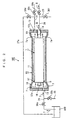
Fig. 1 is a model diagram showing an exemplary spiral
wound membrane module according to an embodiment of the present
invention;
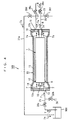
Figs. 2 and 3 are schematic sectional views showing an
exemplary method of running a spiral wound membrane module
according to the present invention;
Fig. 4 is a schematic sectional view showing another
exemplary method of running a spiral wound membrane module
according to the present invention;
Fig. 5 is a partially fragmented perspective view of a
spiral wound membrane element employed for the spiral wound
membrane module shown in Fig. 1;
Fig. 6 is a schematic sectional view showing still another
exemplary method of running a spiral wound membrane module
according to the present invention;
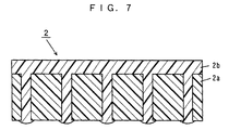
Fig. 7 s a sectional view of a separation membrane
employed for the spiral wound membrane element shown in Fig.
5;
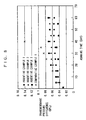
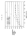
Fig. 8 illustrates time change of transmembrane pressure
differences of spiral wound membrane modules according to
Inventive Examples 1 to 3 and comparative example 1;
Fig. 9 illustrates time change of transmembrane pressure
differences of spiral wound membrane modules according to
Inventive Examples 4 and 5 and comparative example 2; and
Fig. 10 is a schematic sectional view of a spiral wound
membrane module employed for a treatment system according to
the present invention.
DESCRIPTION OF THE PREFERRED EMBODIMENTS
(1) First Embodiment
Fig. 1 is a schematic sectional view showing an exemplary
spiral wound membrane module 100 according to a first
embodiment of the present invention.
As shown in Fig. 1, the spiral wound membrane module 100
is formed by storing a spiral wound membrane element 1 in a
pressure vessel (pressure-resistant vessel) 10. The pressure
vessel 10 is formed by a tubular case 11 and a pair of end plates
12a and 12b. The first end plate 12a is formed with a raw water
inlet 13, and the second end plate 12b is formed with a raw
water outlet 15. A permeate outlet 14 is provided on the
central portion of the second end plate 12b. The structure
of the pressure vessel 10 is not restricted to that shown in
Fig. 1 but a pressure vessel of a side entry shape having a
tubular case provided with a raw water inlet and a raw water
outlet as described later.
The spiral wound membrane element 1 having a packing 17
mounted in the vicinity of an end of its outer peripheral surface
is charged in the tubular case 11, and both opening ends of
the tubular case 11 are sealed with the end plates 12a and 12b
respectively. A first opening end of a water collection pipe
5 is engaged with the permeate outlet 14 of the end plate 12b,
and an end cap 16 is mounted on a second opening end thereof.
The packing 17 divides the internal space of the pressure vessel
10 into a first liquid chamber 18 and a second liquid chamber
19.
The raw water inlet 13 of the spiral wound membrane module
100 is connected to a raw water tank 500 through a pipe 25.
A valve 30a is interposed in the pipe 25, and a pipe 26 having
a valve 30b interposed therein is connected downstream the
valve 30a. A pipe 27 having a valve 30c interposed therein
is connected to the raw water outlet 15, and a pipe 27a having
a valve 30d interposed therein is connected upstream the valve
30c of the pipe 27. The raw water outlet 15 is connected to
the raw water tank 500 through the pipe 27a. A pipe 28 having
a valve 30e interposed therein is connected to the permeate
outlet 14, and a pipe 29 having a valve 30f interposed therein
is connected upstream the valve 30e.
Fig. 5 is a partially fragmented perspective view of the
spiral wound membrane element 1 employed for the spiral wound
membrane module 100 shown in Fig. 1.
As shown in Fig. 5, the spiral wound membrane element
1 is formed by superposing separation membranes 2 on both
surfaces of a permeate spacer 3 made of a net of synthetic resin
and bonding the former to the latter on three sides thereby
forming an envelope membrane 4, mounting an opening of the
envelope membrane 4 on the water collection pipe 5 and spirally
winding the envelope membrane 4 on the outer peripheral surface
of the water collection pipe 5 along with a raw water spacer
6 formed by a net of synthetic resin. The outer peripheral
surface of the spiral wound membrane element 1 is covered with
a sheath member.
This spiral wound membrane element 1 can be subjected
to back wash reverse filtration with a back pressure of 0.05
to 0.3 MPa by employing the separation membranes 2 having a
structure described later.
Figs. 2 and 3 are schematic sectional views showing an
exemplary method of running a spiral wound membrane module
according to the present invention. This running method is
applied to the spiral wound membrane module 100 shown in Fig.
1, and Fig. 2 shows a running method in filtration, while Fig.
3 shows a running method in washing.
As shown in Fig. 2, the valves 30a and 30e of the pipes
25 and 28 are opened and the valves 30b, 30c, 30d and 30f of
the pipes 26, 27, 27a and 29 are closed in filtration.
Raw water 7 taken from the raw water tank 500 is fed into
the pressure vessel 10 from the raw water inlet 13 through the
pipe 25. In the spiral wound membrane module 100, the fed raw
water 7 is introduced into the first liquid chamber 18 of the
pressure vessel 10 from the raw water inlet 13, and further
fed into the spiral wound membrane element 1 from an end thereof .
As shown in Fig. 5, the raw water 7 fed into the spiral
wound membrane element 1 from the first end surface thereof
linearly flows toward the second end surface along the raw water
spacer 6 in a direction (axial direction) parallel to the water
collection pipe 5. In the process of the flow of the raw water
7 along the raw water spacer 6, part of the raw water 7 is
permeated through the separation membranes 2 due to the
pressure difference between the raw water side and a permeate
side. This permeate 8 flows into the water collection pipe
5 along the permeate spacer 3, and is discharged from the end
of the water collection pipe 5. The remaining raw water 7a
not permeated through the separation membranes 2 is discharged
from the second end surface of the spiral wound membrane element
1.
The permeate 8 discharged from the end of the water
collection pipe 5 is taken out from the pressure vessel 10 from
the permeate outlet 14 through the pipe 28, as shown in Fig.
2. The raw water 7a discharged from the second end surface
of the spiral wound membrane element 1 is guided into the second
liquid chamber 19. In this case, the valve 30c of the pipe
27 connected to the raw water outlet 15 and the valve 30d of
the pipe 27a are closed, whereby permeation through the
separation membranes 2 is facilitated in the spiral wound
membrane element 1 for performing dead end filtration.
In the aforementioned filtration process, suspended,
colloidal or dissolved matter contained in the raw water 7 is
deposited on the membrane surfaces of the separation membranes
2 of the spiral wound membrane element 1 as contaminants. In
particular, contaminants are readily deposited on the membrane
surfaces of the separation membranes 2 in dead end filtration.
Such deposition of contaminants results in reduction of the
water permeation velocity, and hence the contaminants are
removed by the following washing:
As shown in Fig. 3, the valves 30a, 30e and 30d of the
pipes 25, 28 and 27a are closed and the valves 30b, 30f and
30c of the pipes 26, 29 and 27 are opened in washing, for
performing back wash reverse filtration.
In this back wash reverse filtration, wash water 21 is
fed to the opening end of the water collection pipe 5 from the
permeate outlet 14 through the pipes 29 and 28, and introduced
into the water collection pipe 5. The wash water 21 is prepared
from the permeate 8, for example. The wash water 21 introduced
into the water collection pipe 5 is guided into the separation
membranes 2 from the outer peripheral surface of the water
collection pipe 5, and permeated through the separation
membranes 2 in a direction opposite to that in filtration. At
this time, contaminants deposited on the membrane surfaces of
the separation membranes 2 are separated from the separation
membranes 2. The outer peripheral surface of the spiral wound
membrane element 1 is covered with the sheath member, whereby
the wash water 21 permeated through the separation membranes
2 axially flows through the spiral wound membrane element 1
along the raw water spacer 6, and is discharged into the first
and second liquid chambers 18 and 19 from both ends of the spiral
wound membrane element 1. Further, the wash water 21 is taken
out from the raw water inlet 13 and the raw water outlet 15
through the pipes 26 and 27 respectively.
In this case, pressures on the sides of the permeate
outlet 14, the raw water inlet 13 and the raw water outlet 15
are set to apply a back pressure of 0.05 to 0.3 MPa to the
separation membranes 2. Thus, a necessary amount of the wash
water 21 can be fed in a short time, so that contaminants
clogging in pores of the separation membranes 2 can be
effectively separated. Further, the separated contaminants
can be inhibited from being captured by the raw water spacer
6 before the same are discharged from the end of the spiral
wound membrane element 1, to be effectively removed.
While the wash water 21 taken out from the raw water inlet
13 is totally discharged from the system as waste water in this
example, the wash water 21 may alternatively be partially
discharged from the system as waste water and partially
recycled as the raw water 7. For example, a further pipe may
be provided downstream the valve 30b of the pipe 27 and connected
to the raw water tank 500, for partially returning the wash
water 21 to the raw water tank 500.
While the wash water 21 taken out from the raw water outlet
15 is totally discharged from the system as waste water in this
example, the wash water 21 may alternatively be partially
discharged from the system as waste water and partially
recycled as the raw water 7. For example, the valves 30c and
30d of the pipes 27 and 27a may be opened for partially returning
the wash water 21 to the raw water tank 500 through the pipe
27a.
While the wash water 21 is discharged from both ends of
the spiral wound membrane element 1 and taken out from the raw
water inlet 13 and the raw water outlet 15 through the pipes
26 and 27 respectively in back wash reverse filtration in the
example shown in Fig. 3, the pressures on the sides of the
permeate outlet 14 and the raw water inlet 13 may alternatively
be so set that the wash water 21 is discharged into the first
liquid chamber 18 from the first end of the spiral wound membrane
element 1 and taken out from the raw water inlet 13 through
the pipe 26. In this case, the valve 30c of the pipe 27 and
the raw water outlet 15 are closed. Further alternatively,
the pressures on the sides of the permeate outlet 14 and the
raw water outlet 15 may be so set that the wash water 21 is
discharged into the second liquid chamber 19 from the second
end of the spiral wound membrane element 1 and taken out from
the raw water outlet 15 through the pipe 27. In this case,
the valve 30b of the pipe 26 and the raw water inlet 13 are
closed.
After performing back wash reverse filtration in the
aforementioned manner, the valves 30b and 30f of the pipes 26
and 29 are closed and the valve 30a of the pipe 25 is opened.
Thus, raw water 31 taken from the raw water tank 500 is fed
into the pressure vessel 10 from the raw water inlet 13 through
the pipe 25, and introduced into the first liquid chamber 18.
The raw water 31 is fed into the spiral wound membrane element
1 from the first end thereof, axially flows through the spiral
wound membrane element 1 along the raw water spacer 6 and is
thereafter discharged from the second end. Thus, contaminants
separated from the separation membranes 2 are carried from the
first end toward the second end of the spiral wound membrane
element 1 along with the raw water 31, and discharged from the
second end of the spiral wound membrane element 1 into the second
liquid chamber 19 along with the wash water 21 remaining in
the spiral wound membrane element 1. Further, the contaminants
are taken out from the pressure vessel 10 from the raw water
outlet 15 through the pipe 27 along with the raw water 31.
Therefore, the contaminants separated from separation
membranes 2 in the spiral wound membrane element 1 can be quickly
discharged from the system by performing flushing of feeding
the raw water 31 in the same direction as that in filtration
after back wash reverse filtration. Thus, the contaminants
separated from the separation membranes 2 can be prevented from
adhering to the separation membranes 2 again.
According to the aforementioned running method in
washing, contaminants deposited on the separation membranes
2 in filtration can be effectively removed, whereby stable
running can be performed without reducing the permeate flux
over a long period also in dead end filtration readily causing
deposition of contaminants on the membrane surfaces.
While flushing of axially feeding the raw water 31 is
performed after back wash reverse filtration in this example,
the former may alternatively be performed before the latter.
According to this washing method, most contaminants captured
on the membrane surface of the spiral wound membrane element
1 are removed by flushing, and contaminants remaining on the
membrane surface of the spiral wound membrane element 1 can
be removed by further introducing the wash water 21. Therefore,
an effect similar to that of the aforementioned back wash
reverse filtration can be attained also in this case.
Alternatively, flushing of axially feeding the raw water
31 may be performed in parallel with back wash reverse
filtration. For example, the valves 30a, 30b, 30c and 30f of
the pipes 25, 26, 27 and 29 may be simultaneously opened in
washing for feeding the wash water 21 from the permeate side
while feeding the raw water 31 from the raw water side. In
this case, an effect similar to that attained when feeding the
raw water 31 after back wash reverse filtration as described
above can be attained.
While the raw water 31 is fed from the raw water inlet
13 and taken out from the raw water outlet 15 in this example,
the raw water 31 may alternatively be fed from the raw water
outlet 15 and taken out from the raw water inlet 13, to be fed
through the spiral wound membrane element 1 in the direction
opposite to that in filtration. In this case, an effect similar
to that attained when feeding the raw water 31 in the same
direction as that in filtration as described above can be
attained.
When the raw water 31 is fed in the same direction as
that in filtration, contaminants deposited on a side closer
to the second liquid chamber 19 of the spiral wound membrane
element 1 can be readily removed and discharged in particular.
When the raw water 31 is fed in the direction opposite to that
in filtration, contaminants deposited on a side closer to the
first liquid chamber 18 of the spiral wound membrane element
1 can be readily removed and discharged in particular.
Further alternatively, raw water may be successively fed
in the same direction as and in the opposite direction to that
in filtration. In this case, contaminants distributed along
the overall spiral wound membrane element 1 can be
homogeneously removed and discharged.
While the raw water 31 taken out from the raw water outlet
15 is totally discharged from the system as waste water in this
example, the raw water 31 may alternatively be partially
discharged from the system as waste water and partially
recycled as raw water. For example, the valves 30c and 30d
of the pipes 27 and 27a may be opened for partially returning
the raw water 31 to the raw water tank 500 through the pipe
27a.
According to this exemplary running method shown in Figs.
2 and 3, contaminants deposited on the membrane surface of the
spiral wound membrane element 1 can be sufficiently removed,
whereby dead end filtration can be stably performed while
maintaining a high permeate flux in the spiral wound membrane
module 100 shown in Fig. 1, for efficiently obtaining the
permeate 8. In this case, dead end filtration is performed,
whereby no large pump may be required for feeding the raw water
7 but the scale of the system can be reduced. Thus, the system
cost is reduced.
In this example, the fed raw water 7 (Fig. 2) may contain
a chemical such as sodium hypochlorite having a contaminant
separating function such as a function of dissolving,
decomposing or separating contaminants or a sterilizing
function. When the raw water 7 fed into the spiral wound
membrane element 1 contains sodium hypochlorite having a
contaminant separating function and a sterilizing function,
for example, contaminants adhering to the membrane surface of
the spiral wound membrane element 1 can be separated and
deposition of contaminants can be suppressed, while
microorganisms can be inhibited from propagating on the
membrane surface. Thus, the spiral wound membrane element 1
can attain further stable performance over a long period.
Alternatively, the raw water 7 may contain ozone,
hydrogen peroxide, chloramine or peracetic acid in place of
sodium hypochlorite. Such a chemical having a sterilizing
function can inhibit microorganisms from propagating on the
membrane surface of the spiral wound membrane element 1
similarly to sodium hypochlorite.
The chemical is injected into the raw water 7 before the
raw water 7 is fed into the spiral wound membrane module 100,
for example.
The chemical may be continuously and regularly or
intermittently injected into the raw water 7. When the
chemical is intermittently injected, injection of the chemical
is controlled with a timer, for example. Alternatively, the
state of contamination of the spiral wound membrane element
1 may be checked from the operating pressure or the permeate
flow rate, for injecting the chemical when contaminants are
deposited on the spiral wound membrane element 1, i.e., when
the operating pressure is increased or the permeate flow rate
is reduced. In this case, a measuring instrument such as an
operating pressure gauge, a permeate flow meter or a
transmembrane pressure difference meter is set in an apparatus
into which the spiral wound membrane module 100 is assembled,
for injecting the chemical according to a signal received from
the measuring instrument.
In addition to the aforementioned chemical having a
contaminant separating function and/or a sterilizing function,
a flocculant may be injected into the raw water 7. In this
case, contaminants contained in the raw water 7 are so
flocculated that the spiral wound membrane element 1 can
readily capture contaminants, possibly permeated through the
membranes of the spiral wound membrane element 1 if the raw
water 7 contains no flocculant, on the membrane surface due
to the flocculating function. The contaminants captured on
the membrane surface of the spiral wound membrane element 1
in the aforementioned manner can be discharged from the system
by the aforementioned back wash reverse filtration with a high
back pressure.
In this example, the permeate 8 containing a chemical
having a contaminant separating function such as a function
of dissolving, decomposing or separating contaminants may be
employed as the wash water 21 (Fig. 3) applied to back wash
reverse filtration. Alternatively, the permeate 8 may contain
a chemical having a sterilizing function. For example, the
permeate 8 containing sodium hypochlorite of 1 to 10000 ppm
in concentration, chloramine of 0.1 to 10 ppm in concentration,
hydrogen peroxide of 10 to 10000 ppm in concentration, sulfuric
acid of pH 1 to 3, nitric acid of pH 1 to 3, hydrochloric acid
of pH 1 to 3, sodium hydroxide of pH 10 to 13, peracetic acid
of 10 to 10000 ppm in concentration, isopropyl alcohol of 0.1
to 50 % in concentration, citric acid of 0.2 to 2 % in
concentration or oxalic acid of 0.2 to 2 % in concentration
is employed as the wash water 21. When the wash water 21
contains such a chemical, contaminants adhering to the membrane
surface of the spiral wound membrane element 1, particularly
those clogging in the pores of the separation membranes 2 can
be effectively removed, and microorganisms can be inhibited
from propagating on the membrane surface.
Particularly when turbid raw water 7 (Fig. 2) containing
a large quantity of contaminants is subjected to dead end
filtration, turbid components (contaminants) contained in the
raw water 7 are captured on the separation membranes 2 of the
spiral wound membrane element 1 in a large quantity to clog
in pores of the separation membranes 2. If only the permeate
8 is employed as the wash water 21 in back wash reverse
filtration, therefore, it is difficult to completely remove
the contaminants. When the aforementioned chemical is
injected into the permeate 8 employed as the wash water 21 for
back wash reverse filtration in this case, contaminants can
be readily removed for enabling effective washing.
The chemical may be continuously injected into the
permeate 8, or the chemical may be injected after performing
back wash reverse filtration with the permeate 8 a number of
times.
In this example, the raw water 31 (Fig. 3) fed from at
least one end of the spiral wound membrane element 1 to axially
flow through the spiral wound membrane element 1 in washing
may contain the aforementioned chemical having a contaminant
removing function or a sterilizing function. When the raw
water 31 contains such a chemical, contaminants adhering to
the membrane surface of the spiral wound membrane element 1,
particularly those deposited on the membrane surface to form
a cake layer can be readily removed while microorganisms can
be inhibited from propagating on the membrane surface.
Particularly when the pores of the membranes of the spiral
wound membrane element 1 are clogged with contaminants and a
cake layer is simultaneously formed on the membrane surfaces
due to deposition of contaminants, the raw water 31 containing
the chemical is preferably regularly or periodically
introduced into the spiral wound membrane element 1 from at
least one end thereof and axially fed through the spiral wound
membrane element 1 in parallel with back wash reverse
filtration performed by introducing the wash water 21
containing the chemical from at least one opening end of the
perforated hollow pipe 5. Thus, the clogging in the pores of
the membranes of the spiral wound membrane element 1 and the
cake layer formed on the membrane surfaces can be
simultaneously removed for enabling effective washing.
When the aforementioned spiral wound membrane element
1 is washed, the spiral wound membrane element 1 may be soaked
in the wash water 21 or the raw liquid 31 containing the chemical
for several 10 minutes to several hours after introducing the
wash water 21 containing the chemical into the spiral wound
membrane element 1 from an end of the water collection pipe
2 or introducing the raw liquid 31 containing the chemical from
at least one end of the spiral wound membrane element 1. Thus,
contaminants clogging in the pores of the membranes of the
spiral wound membrane element 1 and those deposited on the
membrane surfaces to form a cake layer can be further readily
removed for enabling more effective washing. Further,
microorganisms can be more effectively inhibited from
propagating on the membrane surfaces. In addition,
contaminants can be discharged from the spiral wound membrane
module 100 by further performing back wash reverse filtration
on the spiral wound membrane element 1 soaked in the wash water
21 or the raw water 31 containing the chemical or feeding the
raw water 31 from an end of the spiral wound membrane element
1.
The spiral wound membrane element 1 is washed by the
aforementioned soaking once to several times a day or in
response to change of running conditions for the spiral wound
membrane module 100 such as increase of the operating pressure
or reduction of the permeate flow rate, for example.
Fig. 4 is a schematic sectional view showing another
exemplary method of running a spiral wound membrane module
according to the present invention. The running method shown
in Fig. 4, employed in filtration, is applied to the spiral
wound membrane module 100 shown in Fig. 1 also in this case.
In this example, a running method in washing is similar to the
aforementioned running method shown in Fig. 3.
As shown in Fig. 4, the valves 30a, 30e and 30d of the
pipes 25, 28 and 27a are opened and the valves 30b, 30c and
30f of the pipes 26, 27 and 29 are closed in filtration.
In this case, the raw water 7 taken from the raw water
tank 500 is introduced into the first liquid chamber 18 of the
pressure vessel 10 from the raw water inlet 13 through the pipe
25, similarly to the case shown in Fig. 2. Further, the raw
water 7 is fed into the spiral wound membrane element 1 from
the first end thereof.
As shown in Fig. 5, partial raw water is permeated through
the separation membranes 2, flows into the water collection
pipe 5 and is discharged from the end of the water collection
pipe 5 as the permeate 8 in the spiral wound membrane element
1. The remaining raw water 7a not permeated through the
separation membranes 2 is discharged from the second end
surface of the spiral wound membrane element 1.
The permeate 8 discharged from the end of the water
collection pipe 5 is taken out from the pressure vessel 10 from
the permeate outlet 14 through the pipe 28, as shown in Fig.
4. The raw water 7a discharged from the second end surface
of the spiral wound membrane element 1 is guided into the second
liquid chamber 19 and thereafter taken out from the raw water
outlet 15 through the pipe 27a, to be returned to the raw water
tank 500. Thus, filtration is performed in the spiral wound
membrane module 100 while taking out the partial raw water 7a
from the raw water outlet 15 in this example. Thus, retention
of any liquid can be suppressed in the clearance between the
outer peripheral surface of the spiral wound membrane element
1 and the inner peripheral surface of the pressure vessel 10.
Further, an axial flow of the raw water from the first end toward
the second end is formed in the spiral wound membrane element
1, whereby partial contaminants can be discharged from the
pressure vessel 10 along with the raw water 7a while suppressing
sedimentation of contaminants contained in the raw water.
While the valve 30d is regularly opened for taking out
the raw water 7a in the above description, the valve 30d may
alternatively be intermittently opened for taking out the raw
water 7a. Also in this case, the separation membranes 2 can
be inhibited from adhesion of contaminants similarly to the
case of regularly taking out the raw water 7a.
While the raw water 7a taken out from the pressure vessel
10 is totally returned to the raw water tank 500 in the above
description, the taken out raw water 7a may alternatively be
partially discharged from the system. For example, the valves
30d and 30c may be opened for partially discharging the raw
water 7a from the system through the pipe 27.
Also in this example, back wash reverse filtration is
performed with a high back pressure in washing by the running
method in washing shown in Fig. 3 while introducing the raw
water 31. Thus, contaminants deposited on the separation
membranes 2 in filtration can be effectively removed.
According to the running method of this example, as
hereinabove described, contaminants deposited on the membrane
surface can be sufficiently removed, whereby stable running
can be performed without reducing the permeate flux over a long
period.
Particularly in this example, partial contaminants can
be discharged from the pressure vessel 10 along with the raw
water 7a while inhibiting contaminants contained in the raw
water 7 from sedimenting on the membrane surface by taking out
the partial raw water 7a from the pressure vessel 10 in
filtration as shown in Fig. 4, whereby more stable filtration
running can be performed. In this case, the raw water 7a taken
out from the raw water outlet 15 is circulated through the pipe
27a, whereby the permeate 8 can be obtained with high recovery.
Further, no large pump may be employed for feeding the raw water
7 but the scale of the system can be reduced. Thus, the system
cost is reduced.
Also in running of the spiral wound membrane element 1
shown in Fig. 4, the fed raw water 7 may contain a chemical
such as sodium hypochlorite having a contaminant removing
function or a sterilizing function or a flocculant, similarly
to that in running of the spiral wound membrane element 1 shown
in Fig. 1. Further, the permeate 8 employed as the wash water
21 in washing and the raw water 31 fed from at least the end
of eth spiral wound membrane element 1 in washing may contain
a chemical such as sodium hypochlorite having a contaminant
removing function or a sterilizing function.
While the spiral wound membrane module 100 comprising
the single spiral wound membrane element 1 is run in the above
description, the running method according to the present
invention is also applicable to a spiral wound membrane module
comprising a plurality of spirally wound membrane elements.
Fig. 6 is a schematic sectional view showing still another
exemplary method of running a spirally wound membrane module
according to the present invention.
As shown in Fig. 6, this spiral wound membrane module
100 is formed by storing a plurality of spirally wound membrane
elements 1 in a pressure vessel 110. The pressure vessel 110
is formed by a tubular case 111 and a pair of end plates 120a
and 120b. A raw water outlet 130 is formed on the bottom portion
of the tubular case 111, and a raw water outlet 131 is formed
on the upper portion thereof. Thus, the pressure vessel 110
has a side entry shape. The raw water outlet 131 is employed
also for deairing. Permeate outlets 140 are provided on the
central portions of the end plates 120a and 120b.
The plurality of spiral wound membrane elements 1 having
water collection pipes 5 serially connected with each other
by interconnectors 116 are stored in the tubular case 111, and
both opening ends of the tubular case 111 are sealed with the
end plates 120a and 120b respectively. Each of the spiral wound
membrane elements 1 is formed by the spiral wound membrane
element 1 shown in Fig. 5. Single ends of the water collection
pipes 5 of the endmost spiral wound membrane elements 1 are
engaged with the permeate outlets 140 of the end plates 120a
and 120b respectively through adaptors 115. Packings 170 are
mounted on portions closer to single ends of the outer
peripheral surfaces of the spiral wound membrane elements 1,
to separate the internal space of the pressure vessel 110 into
a plurality of liquid chambers.
The raw water inlet 130 of the spiral wound membrane
module 100 is connected to a raw water tank 500 through a pipe
55. A valve 60a is interposed in the pipe 55, and a pipe 56
having a valve 60b interposed therein is connected downstream
the valve 30a. A pipe 57 having a valve 60c interposed therein
is connected to the raw water outlet 131, and a pipe 57a having
a valve 60d interposed therein is connected upstream the valve
60c of the pipe 57. The raw water outlet 131 is connected to
the raw water tank 500 through the pipe 57a. A pipe 58a having
a valve 60e interposed therein is connected to the permeate
outlet 140 of the end plate 120a, and a pipe 59a having a valve
60g interposed therein is connected upstream the valve 60e.
A pipe 58b having a valve 60f interposed therein is connected
to the permeate outlet 140 of the end plate 120b, and a pipe
59b having a valve 60h interposed therein is connected upstream
the valve 60f.
In filtration of the spiral wound membrane module 100,
the valves 60a, 60e and 60f of the pipes 55, 58a and 58b are
opened, and the valves 60b, 60g, 60h, 60c and 60d of the pipes
56, 59a, 59b, 57 and 57a are closed.
Raw water 7 taken from the raw water tank 500 is fed into
the pressure vessel 110 from the raw water inlet 130 through
the pipe 55. In the spiral wound membrane module 100, the raw
water 7 fed from the raw water inlet 130 is introduced into
the endmost spiral wound membrane element 1 closer to the end
plate 120a from a first end surface thereof. In this spiral
wound membrane element 1, partial raw water is permeated
through the separation membranes 2 to flow into the water
collection pipe 5, and discharged from an end of the water
collection pipe 5 as permeate 8, as shown in Fig. 6. The
remaining raw water 7a not permeated through the separation
membranes 2 is discharged from a second end surface. The
discharged raw water 7a is introduced into the subsequent
spiral wound membrane element 1 from a first end surface thereof,
and separated into permeate 8 and raw water 7a similarly to
the above. Thus, membrane separation is performed in each of
the plurality of spiral wound membrane elements 1 serially
connected with each other. In this case, the valves 60c and
60d of the pipes 57 and 57a are closed and hence permeation
through the separation membranes 2 is facilitated in each
spiral wound membrane element 1, for performing dead end
filtration in the spiral wound membrane module 100.
In the aforementioned filtration process, contaminants
contained in the raw water 7 are deposited on the membrane
surfaces of the separation membranes 2 of the spiral wound
membrane elements 1. Particularly when dead end filtration
is performed in the spiral wound membrane module 100 comprising
the plurality of spiral wound membrane elements 1 as described
above, contaminants are readily deposited on the membrane
surfaces of the separation membranes 2. Such deposition of
contaminants results in reduction of the water permeation
velocity, and hence the contaminants are removed by the
following washing:
In washing, the valves 60a, 60e, 60f and 60d of the pipes
55, 58a, 58b and 57a are closed and the valves 60b, 60c, 60g
and 60h of the pipes 56, 57, 59a and 59b are opened for performing
back wash reverse filtration.
In back wash reverse filtration, wash water 21 is fed
to first ends of the water collection pipes 5 closer to the
end plate 120a from the permeate outlet 140 through the pipes
59a and 58a. Further, wash water 21 is fed to second ends of
the water collection pipes 5 closer to the end plate 120b from
the permeate outlet 140 through the pipes 59b and 58b. Thus,
the wash water 21 is introduced into the water collection pipes
5 from both ends thereof. The wash water 21 introduced into
the water collection pipes 5 is guided into the separation
membranes 2 from the outer peripheral surface of the water
collection pipe 5 in each spiral wound membrane element 1, and
permeated through the separation membranes 2 in a direction
opposite to that in filtration. At this time, contaminants
deposited on the membrane surfaces of the separation membranes
2 are separated from the separation membranes 2. The wash water
21 permeated through the separation membranes 2 axially flows
through the spiral wound membrane element 1 along a raw water
spacer 6, and is discharged from both ends of each spiral wound
membrane element 1. The discharged wash water 21 is taken out
from the raw water inlet 130 and the raw water outlet 131 through
the pies 56 and 57 respectively.
In this case, pressures on the sides of the
permeate
outlets 140, the
raw water inlet 130 and the
raw water outlet
131 are set to apply a back pressure of 0.05 to 0.3 MPa to the
separation membranes 2 of each spiral wound membrane element
While the wash water 21 taken out from the raw water inlet
130 is totally discharged from the system as waste water in
this example, the wash water 21 may alternatively be partially
discharged from the system as waste water and partially
recycled as the raw water 7. For example, a further pipe may
be provided downstream the valve 60b of the pipe 56 and connected
to the raw water tank 500, thereby partially returning the wash
water 21 to the raw water tank 500.
While the wash water 21 taken out from the raw water outlet
131 is totally discharged from the system as waste water in
this example, the wash water 21 may alternatively be partially
discharged from the system as waste water and partially
recycled as the raw water 7. For example, the valves 60c and
60d of the pipes 57 and 57a may be opened for partially returning
the wash water 21 to the raw water tank 500 through the pipe
57a.
While the wash water 21 is taken out from the raw water
inlet 130 and the raw water outlet 131 through the pipes 56
and 57 respectively in back wash reverse filtration in the
example shown in Fig. 6, the pressures on the sides of the
permeate outlets 140 and the raw water inlet 130 may
alternatively be so set that the wash water 21 is taken out
from the raw water inlet 130 through the pipe 56. In this case,
the valve 60c of the pipe 57 and the raw water outlet 131 are
closed. Further alternatively, the pressures on the sides of
the permeate outlets 140 and the raw water outlet 131 may be
so set that the wash water 21 is taken out from the raw water
outlet 131 through the pipe 57. In this case, the valve 60b
of the pipe 56 and the raw water inlet 130 are closed.
After performing back wash reverse filtration in the
aforementioned manner, the valves 60b, 60g and 60h of the pipes
56,59a and 59b are closed and the valve 60a of the pipe 55 is
opened. Thus, raw water 31 taken from the raw water tank 500
is fed into the pressure vessel 110 from the raw water inlet
130 through the pipe 55. The raw water 31 is introduced into
each spiral wound membrane element 1 from the first end thereof,
axially flows through the spiral wound membrane element 1 along
the raw water spacer 6 and is thereafter discharged from the
second end. Thus, contaminants separated from the separation
membranes 2 are carried from the first end toward the second
end of the spiral wound membrane element 1 by the raw water
31, and discharged from the second end of the spiral wound
membrane element 1 along with the wash water 21 remaining in
the spiral wound membrane element 1. Further, contaminants
and the wash water 21 are taken out from the pressure vessel
110 from the raw water outlet 131 through the pipe 57 along
with the raw water 31.
Therefore, the contaminants separated from the
separation membranes 2 in each spiral wound membrane element
1 can be quickly discharged from the system by feeding the raw
water 31 in the same direction as that in filtration after back
wash reverse filtration. Thus, the contaminants separated
from the separation membranes 2 can be prevented from adhering
to the separation membranes 2 again.
While flushing of axially feeding the raw water 31 is
performed after back wash reverse filtration in this example,
the former may alternatively be performed before the latter.
According to this washing method, most contaminants captured
on the membrane surface of the spiral wound membrane element
1 are removed by flushing, and contaminants remaining on the
membrane surface of the spiral wound membrane element 1 can
be removed by further introducing the wash water 21. Therefore,
an effect similar to that of the aforementioned back wash
reverse filtration can be attained also in this case.
Further alternatively, the raw water 31 may be axially
fed in parallel with back wash reverse filtration. For example,
the valves 60a, 60b, 60c, 60g and 60h of the pipes 55, 56, 57,
59a and 59b may be simultaneously opened in washing for feeding
the wash water 21 from the permeate side while feeding the raw
water 31 from the raw water side. In this case, an effect
similar to that attained when feeding the raw water 31 after
back wash reverse filtration as described above can be
attained.
While the raw water 31 is fed from the raw water inlet
130 and taken out from the raw water outlet 131 in this example,
raw water may alternatively be fed from the raw water outlet
131 and taken out from the raw water inlet 130 to be fed in
the direction opposite to that in filtration in each spiral
wound membrane element 1. In this case, an effect similar to
that attained when feeding the raw water 31 in the same direction
as that in filtration as described above can be attained.
Further alternatively, raw water may be successively fed in
the same direction as and in the opposite direction to that
in filtration. In this case, contaminants distributed along
the overall spiral wound membrane element 1 can be
homogeneously removed and discharged.
While the raw water 31 taken out from the raw water outlet
131 is totally discharged from the system as waste water in
this example, the raw water 31 may alternatively be partially
discharged from the system as waste water and partially
recycled as the raw water 7. For example, the valves 60c and
60d of the pipes 57 and 57a may be opened for partially returning
the raw water 31 to the raw water tank 500 through the pipe
57a.
According to the aforementioned running method in
washing, contaminants deposited on the separation membranes
2 in filtration can be effectively removed.
According to this running method, as hereinabove
described, contaminants deposited on the membrane surfaces can
be sufficiently removed, whereby running can be stably
performed while maintaining a high permeate flux also in dead
end filtration readily causing deposition of contaminants on
the membrane surfaces, for efficiently obtaining the permeate
8. In this case, dead end filtration is performed, whereby
no large pump may be employed for feeding the raw water 7 but
the scale of the system can be reduced. Thus, the system cost
is reduced.
Also in this example, the fed raw water 7 may contain
a chemical such as sodium hypochlorite having a contaminant
removing function or a sterilizing function, similarly to the
method of running a spiral wound membrane element and a spiral
wound membrane module shown in Fig. 1. In this case,
contaminants adhering to the membrane surface of each spiral
wound membrane element 1 can be removed and inhibited from
deposition, while microorganisms can be inhibited from
propagating on the membrane surface. Thus, the spiral wound
membrane module can attain more stable performance over a long
period.
When washing the spiral wound membrane module, the
permeate 8 containing a chemical such as sodium hypochlorite
having a contaminant removing function or a sterilizing
function may be employed as the wash water 21 for back wash
reverse filtration. In this case, contaminants clogging in
the pores of the spiral wound membrane element 1 can be
effectively removed, and microorganisms can be inhibited from
propagating on the membrane surface. Thus, the spiral wound
membrane module attains more stable performance over a long
period.
Further, the raw water 31 containing a chemical having
a contaminant removing function or a sterilizing function may
be fed from at least one end of the spiral wound membrane element
1 in washing. In this case, contaminants deposited on the
membrane surface of each spiral wound membrane element 1 to
form a cake layer can be effectively removed, and
microorganisms can be inhibited from propagating on the
membrane surface. Thus, the spiral wound membrane module
attains more stable performance over a long period.
While the spiral wound membrane module 100 shown in Fig.
6 is subjected to dead end filtration similarly to the example
shown in Fig. 2 in the above description, the spiral wound
membrane module 100 shown in Fig. 6 may alternatively be
subjected to filtration while taking out the partial raw water
7a from the pressure vessel 110 similarly to the example shown
in Fig. 4.
In filtration of the spiral wound membrane module 100
shown in Fig. 6, for example, the valve 60d of the pipe 57a
may be regularly or intermittently opened for taking out the
partial raw water 7a not permeated through the separation
membranes 2 of the spiral wound membrane element 1 in the raw
water 7 fed into the pressure vessel 110 from the pressure vessel
110 from the raw water outlet 131 through the pipe 57a and
returning the same to the raw water tank 500. Thus, retention
of any liquid can be suppressed in the clearance between the
outer periphery of each spiral wound membrane element 1 and
the inner peripheral surface of the pressure vessel 110.
Further, an axial flow of raw water is formed from the first
end toward the second end in each spiral wound membrane element
1, whereby partial contaminants can be discharged from the
pressure vessel 110 along with the raw water 7a while
suppressing sedimentation of contaminants contained in the raw
water.
According to the running method performing filtration
while partially taking out the raw water, more stable running
can be performed without reducing the permeate flux over a long
period. In this case, the taken out raw water 7a is circulated
through the pipe 57a, whereby the permeate 8 can be obtained
with high recovery. Further, no large pump may be employed
for feeding the raw water 7 but the scale of the system can
be reduced. Thus, the system cost is reduced.
Fig. 7 is a sectional view of each separation membrane
2 employed for the spiral wound membrane element 1 shown in
Fig. 5. The separation membrane 2 is formed by closely
integrating a permeable membrane body 2b having a substantial
separation function with a surface of a porous reinforcing
sheet (porous sheet member) 2a.
The permeable membrane body 2b is made of a single type
of polysulfone resin or a mixture of at least two types of
polysulfone resin, or a copolymer or a mixture of polysulfone
resin and a polymer such as polyimide or fluorine-containing
polyimide resin.
The porous reinforcing sheet 2a is made of woven fabric,
nonwoven fabric, a mesh net or a foaming sintered sheet prepared
from polyester, polypropylene, polyethylene or polyamide, and
the nonwoven fabric is preferable in consideration of the
membrane forming property and the cost.
The porous reinforcing sheet 2a and the permeable
membrane body 2b are bonded to each other in such an anchored
state that the resin component forming the permeable membrane
body 2b is partially charged into pores of the porous
reinforcing sheet 2a.
Back pressure strength of the separation membrane 2 lined
with the porous reinforcing sheet 2a is improved to 0.4 to 0.5
MPa beyond 0.2 MPa. A method of defining the back pressure
strength is described later.
In order to attain back pressure strength of at least
0.2 MPa by employing nonwoven fabric as the material for the
porous reinforcing sheet 2a, the nonwoven fabric is preferably
0.08 to 0.15 mm in thickness and 0.5 to 0.8 g/cm3 in density.
If the thickness is smaller than 0.08 mm or the density is
smaller than 0.5 g/cm3, sufficient strength for serving as the
reinforcing sheet 2a cannot be attained but it is difficult
to ensure back pressure strength of at least 0.2 MPa for the
separation membrane 2. If the thickness is larger than 0.15
mm or the density is larger than 0.8 g/cm3, on the other hand,
filtration resistance of the porous reinforcing sheet 2a may
be increased or the anchoring effect to the nonwoven fabric
(porous reinforcing sheet 2a) is reduced to readily cause
separation between the permeable membrane body 2b and the
nonwoven fabric.
A method of preparing the
aforementioned separation
membrane 2 is now described. First, a solvent, a non-solvent
and a swelling agent are added to polysulfone and the mixture
is heated/dissolved for preparing a homogeneous membrane
forming solution. The polysulfone resin is not particularly
restricted so far as the same has at least one (-SO
2-) site in
its molecular structure, as shown in the following structural
formula (1):
where R represents a bivalent aromatic, alicyclic or aliphatic
hydrocarbon radical or a bivalent organic radical formed by
bonding such hydrocarbon radicals with a bivalent organic
bonding radical.
Preferably, polysulfone expressed in any of the
following structural formulas (2) to (4) is employed:
As the solvent for polysulfone, N-methyl-2-pyrolidone,
dimethylformamide, dimethylacetamide, dimethylsulfoxide or
the like is preferably employed. As the non-solvent, aliphatic
polyhydric alcohol such as ethylene glycol, diethylene glycol,
propylene glycol, polyethylene glycol or glycerin, lower
aliphatic alcohol such as methanol, ethanol or isopropyl
alcohol or lower aliphatic ketone such as methyl ethyl ketone
is preferably employed.
The content of the non-solvent in the mixture, not
particularly restricted so far as the obtained mixture is
homogeneous, is generally 5 to 50 percent by weight, and
preferably 20 to 45 percent by weight.
As the swelling agent employed for prompting or
controlling formation of a porous structure, metal salt such
as lithium chloride, sodium chloride or lithium nitrate, a
water-soluble polymer such as polyethylene glycol, polyvinyl
alcohol, polyvinyl pyrolidone or polyacrylic acid or metal salt
thereof, formamide or the like is employed. The content of
the swelling agent in the mixture, not particularly restricted
so far as the membrane forming solution is homogeneous, is
generally 1 to 50 percent by weight.
The concentration of polysulfone in the membrane forming
solution is preferably 10 to 30 percent by weight in general.
Permeability of the obtained porous separation membrane is
inferior in practicalness if the concentration exceeds 30
percent by weight, while mechanical strength of the obtained
porous separation membrane is so inferior that sufficient back
pressure strength cannot be attained if the concentration is
smaller than 10 percent by weight.
A film of the aforementioned membrane forming solution
is formed on a nonwoven fabric support. In other words, a
support sheet of nonwoven fabric or the like is successively
taken out from a continuous membrane forming apparatus so that
the membrane forming solution is applied onto its surface. The
membrane forming solution is applied onto the nonwoven fabric
support with a gap coater such as a knife coater or a roll coater.
When the roll coater is employed, for example, the membrane
forming solution is stored between two rolls to be applied onto
the nonwoven fabric support and sufficiently impregnated into
the nonwoven fabric at the same time, and thereafter passed
through a low humidity atmosphere for absorbing a small amount
of moisture contained in the atmosphere in the surface of the
liquid film applied onto the nonwoven fabric and causing
microphase separation on the surface layer of the liquid film.
Thereafter the liquid film is soaked in a solidification water
tank to be entirely phase-separated and solidified, and the
solvent is removed by washing in a washing tank. Thus, the
separation membrane 2 is formed.
Thus, the aforementioned separation membrane 2 having
high back pressure strength is prevented from breakage also
when employed for the spiral wound membrane element 1 shown
in Fig. 1 or 6 and subjected to back wash reverse filtration
with a back pressure of 0.05 to 0.3 MPa.
[Examples]
In each of Inventive Examples 1 to 3 and comparative
example 1, a spiral wound ultrafiltration membrane element
including ultrafiltration membranes having the structure shown
in Fig. 7 as the separation membranes 2 was so prepared as to
perform a continuous water filtration test on the spiral wound
membrane module shown in Fig. 1 comprising this spiral wound
ultrafiltration membrane element.
Table 1 shows the specifications of the spiral wound
ultrafiltration membrane elements employed for Inventive
Examples 1 to 3 and comparative example 1.
| Shape | Spiral |
| Material | Polysulfone |
| Size | 202mm in diameter by 1016mm in length |
| Membrane Area | 40m2 /Element |
Each ultrafiltration membrane employed for the spiral
wound ultrafiltration membrane elements of Inventive Examples
1 to 3 and comparative example 1 was prepared as follows:
16.5 parts by weight of polysulfone (P-3500 by BP Amoco),
50 parts by weight of N-methyl-2-pyrolidone, 24.5 parts by
weight of diethylene glycol and 1 part by weight of formamide
were heated/dissolved for obtaining a homogeneous membrane
forming solution. The membrane forming solution was
impregnated into/applied to the surface of polyester nonwoven
fabric of 0.1 mm in thickness and 0.8 g/cm3 in density with a
roll coater having a coater gap adjusted to 0.13 mm.
Thereafter the nonwoven fabric was passed through an
atmosphere (low humidity atmosphere) having relative humidity
of 25 % and a temperature of 30°C for causing microphase
separation, thereafter soaked in a solidification water tank
of 35°C to be de-solvented and solidified, and thereafter the
remaining solvent was removed by washing in a washing tank for
obtaining a separation membrane 2. The microphase separation
time (the time for passing through the low humidity atmosphere)
for the separation membrane 2 was 4.5 seconds in each of
Inventive Examples 1 and 2.
The ultrafiltration membrane prepared in the
aforementioned manner exhibited a permeate flow rate of 1700
L/m2·hr and back pressure strength of 0.3 MPa, and rejection
of polyethylene oxide having a mean molecular weight of
1,000,000 was 99 %.
The back pressure strength is defined by a pressure
applied when a membrane of 47 mm in diameter is set on a back
pressure strength holder (perforated diameter: 23 mm), a water
pressure is gradually applied from the side of the porous
reinforcing sheet 2a and the permeable membrane body 2b is
separated from the porous reinforcing sheet 2a or the permeable
membrane body 2b and the porous reinforcing sheet 2a are
simultaneously broken.
The rejection of polyethylene oxide was obtained from
concentrations of a raw liquid and a permeated liquid through
the following formula by permeating a polyethylene oxide
solution of 500 ppm in concentration with a pressure of 1
kgf/cm2:
Rejection (%) = [1 - (concentration of permeated
liquid/concentration of raw liquid)] × 100
A continuous water filtration test of each spiral wound
membrane module comprising ultrafiltration membranes prepared
in the aforementioned manner is now described. In this
continuous water filtration test, industrial water (pH: 6 to
8, water temperature: 10 to 30°C) was fed as the raw water 7.
[Inventive Example 1]
In Inventive Example 1, sodium hypochlorite having a
sterilizing function and a contaminant removing function was
regularly injected into the
raw water 7 fed into the spiral
wound membrane module shown in Fig. 1 for performing filtration.
Table 2 shows running conditions for the spiral wound membrane
module in Inventive Example 1.
| Running Method | Constant Flow Rate Filtration |
| Filtration System | Dead End Filtration (Fig.2) |
| Filtration Rate | 2 m3/m2/day |
| Physical Washing Interval | 30 min. |
| Back Wash Reverse Filtration Time | 40 sec. |
| Chemical injection (sodium hypochlorite) | injected into raw water by 1 ppm |
In back wash reverse filtration, the permeate 8 (Fig.
2) was employed as the wash water 21 (Fig. 3) and fed with a
back pressure of 0.1 to 0.2 MPa and a flow rate of 56 L/min.
In this case, the raw water 31 (Fig. 3) was fed into the spiral
wound membrane module after back wash reverse filtration, and
fed through the spiral wound ultrafiltration membrane element
in the same direction as that for feeding the raw water 7 (Fig.
2) in filtration.
The aforementioned filtration and washing were repeated
for continuously running the spiral wound ultrafiltration
membrane element. The relation between the running time and
the transmembrane pressure difference in the spiral wound
ultrafiltration membrane element was investigated.
[Inventive Example 2]
In Inventive Example 2, sodium hypochlorite having a
sterilizing function and a contaminant removing function was
injected into the wash water 21 (Fig. 3) in back wash reverse
filtration of the spiral wound membrane module shown in Fig.
1, for performing back wash reverse filtration with the wash
water 21 (back wash reverse filtration water). Table 3 shows
running conditions for the spiral wound membrane module in
Inventive Example 2.
| Running Method | Constant Flow Rate Filtration |
| Filtration System | Dead End Filtration (Fig.2) |
| Filtration Rate | 2 m3 /m2 /day |
| Physical Washing Interval | 30 min. |
| Back Wash Reverse Filtration Time | 40 sec. |
| Chemical injection (sodium hypochlorite) | injected into back wash reverse filtration water by 5 ppm |
In back wash reverse filtration, the permeate 8 (Fig.
2) was employed as the wash water 21 (Fig. 3) and fed with a
back pressure of 0.1 to 0.2 MPa and a flow rate of 56 L/min.
In this case, the raw water 31 (Fig. 3) was fed into the spi
ral wound membrane module after back wash reverse filtration
, and fed through the spiral wound ultrafiltration membrane
element in the same direction as that for feeding the raw wa
ter 7 (Fig. 2) in filtration.
The aforementioned filtration and washing were repeated
for continuously running the spiral wound ultrafiltration
membrane element. The relation between the running time and
the transmembrane pressure difference in the spiral wound
ultrafiltration membrane element was investigated.
[Inventive Example 3]
In Inventive Example 3, the spiral wound membrane module
shown in Fig. 1 was continuously run for five days, and
thereafter wash water containing sodium hypochlorite having
a sterilizing function and a contaminant removing function was
fed into the spiral wound membrane module for soaking/washing
the spiral wound ultrafiltration membrane element therein.
Table 4 shows running conditions for the spiral wound membrane
module in Inventive Example 3.
| Running Method | Constant Flow Rate Filtration |
| Filtration System | Dead End Filtration (Fig.2) |
| Filtration Rate | 2 m3 /m2 /day |
| Physical Washing Interval | 30 min. |
| Back Wash Reverse Filtration Time | 40 sec. |
| Chemical injection (sodium hypochlorite) | injected into wash water by 100 ppm for soaking for 1 h. |
In back wash reverse filtration, the permeate 8 (Fig.
2) was employed as the wash water 21 (Fig. 3) and fed with a
back pressure of 0.1 to 0.2 MPa and a flow rate of 56 L/min.
In this case, the raw water 31 (Fig. 3) was fed into the spiral
wound membrane module after back wash reverse filtration, and
fed through the spiral wound ultrafiltration membrane element
in the same direction as that for feeding the raw water 7 (Fig.
2) in filtration.
In Inventive Example 3, sodium hypochlorite was properly
injected into the wash water 21 for back wash reverse filtration
in soak washing, and the wash water 21 containing the injected
sodium hypochlorite was employed as wash water for soak
washing.
The aforementioned filtration and washing were repeated
for continuously running the spiral wound membrane module. The
relation between the running time and the transmembrane
pressure difference in the spiral wound ultrafiltration
membrane element was investigated.
[Comparative Example 1]
In comparative example 1, no chemical was injected in
filtration running and washing of the spiral wound membrane
module shown in Fig. 1. Table 5 shows running conditions for
the spiral wound membrane module in comparative example 1.
| Running Method | Constant Flow Rate Filtration |
| Filtration System | Dead End Filtration (Fig.2) |
| Filtration Rate | 2 m3 /m2 /day |
| Physical Washing Interval | 30 min. |
| Back Wash Reverse Filtration Time | 40 sec. |
| Chemical Injection (sodium hypochlorite) | neither into raw water nor into wash water |
In back wash reverse filtration, the permeate 8 (Fig.
2) was employed as the wash water 21 (Fig. 3) and fed with a
back pressure of 0.1 to 0.2 MPa and a flow rate of 56 L/min.
In this case, the raw water 31 (Fig. 3) was fed into the spiral
wound membrane module after back wash reverse filtration, and
fed through the spiral wound ultrafiltration membrane element
in the same direction as that for feeding the raw water 7 (Fig.
2) in filtration.
The aforementioned filtration and washing were repeated
for continuously running the spiral wound membrane module. The
relation between the running time and the transmembrane
pressure difference in the spiral wound ultrafiltration
membrane element was investigated.
Fig. 8 shows time change of the transmembrane pressure
differences of the spiral wound membrane modules in Inventive
Examples 1 to 3 and comparative example 1.
As shown in Fig. 8, microorganisms can be inhibited from
propagating on the membrane surface and contaminants can be
prevented from adhering to the membrane surface in Inventive
Example 1 regularly injecting sodium hypochlorite into the raw
water 7. Therefore, change of the transmembrane pressure
difference of the spiral wound ultrafiltration membrane
element was so small that it was possible to stably run the
spiral wound membrane module continuously over a long period.
In Inventive Example 2 injecting sodium hypochlorite
into the wash water 21 in back wash reverse filtration, the
membrane surface comes into contact with sodium hypochlorite
only at a constant interval, an hence the effect thereof is
reduced as compared with Inventive Example 1. Also in this
case, however, increase of the transmembrane pressure
difference can be sufficiently suppressed in the spiral wound
ultrafiltration membrane element, and change of the
transmembrane pressure difference can be reduced. Therefore,
it was possible to stably run the spiral wound membrane module
continuously over a long period.
In Inventive Example 3, no chemical is injected in
filtration and back wash reverse filtration and hence the
transmembrane pressure difference is increased as the running
time elapses. In this case, however, soak washing is performed
with the wash water containing sodium hypochlorite following
increase of the transmembrane pressure difference, and hence
increase of the transmembrane pressure difference can be
suppressed. Therefore, it was possible to stably run the
spiral wound membrane module continuously over a long period.
In comparative example 1 injecting no chemical injection
in filtration and washing, it was impossible to continuously
run the spiral wound membrane module due to abrupt increase
of the transmembrane pressure difference caused as the running
time elapses.
(2) Second Embodiment
A method of running a spiral wound membrane module
according to a second embodiment of the present invention is
now described. The structure of the spiral wound membrane
module employed in this embodiment is similar to that of the
spiral wound membrane module 100 shown in Fig. 1 or 5.
An exemplary method of running a spiral wound membrane
module according to this embodiment is described with reference
to Figs. 2 and 3. This running method is applied to the spiral
wound membrane module 100 shown in Fig. 1.
As shown in Fig. 2, the valves 30a and 30e of the pipes
25 and 28 are opened and the valves 30b, 30c, 30d and 30f of
the pipes 26, 27, 27a and 29 are closed in filtration.
Raw water 7 taken from the raw water tank 500 is fed into
the pressure vessel 10 from the raw water inlet 13 through the
pipe 25. In the spiral wound membrane module, the fed raw water
7 is introduced into the first liquid chamber 18 of the pressure
vessel 10 from the raw water inlet 13, and further fed into
the spiral wound membrane element 1 from an end thereof.
As shown in Fig. 5, the raw water 7 fed into the spiral
wound membrane element 1 from the first end surface thereof
linearly flows toward the second end surface along the raw water
spacer 6 in a direction (axial direction) parallel to the water
collection pipe 5. In the process of the flow of the raw water
7 along the raw water spacer 6, part of the raw water 7 is
permeated through the separation membranes 2 due to the
pressure difference between the raw water side and a permeate
side. This permeate 8 flows into the water collection pipe
5 along the permeate spacer 3, and is discharged from the end
of the water collection pipe 5. The remaining raw water 7a
not permeated through the separation membranes 2 is discharged
from the second end surface of the spiral wound membrane element
1.
The permeate 8 discharged from the end of the water
collection pipe 5 is taken out from the pressure vessel 10 from
the permeate outlet 14 through the pipe 28, as shown in Fig.
2. The raw water 7a discharged from the second end surface
of the spiral wound membrane element 1 is guided into the second
liquid chamber 19. In this case, the valve 30c of the pipe
27 connected to the raw water outlet 15 and the valve 30d of
the pipe 27a are closed, whereby permeation through the
separation membranes 2 is facilitated in the spiral wound
membrane element 1 for performing dead end filtration.
In the aforementioned filtration process, suspended,
colloidal or dissolved matter contained in the raw water 7 is
deposited on the membrane surfaces of the separation membranes
2 of the spiral wound membrane element 1 as contaminants. In
particular, contaminants are readily deposited on the membrane
surfaces of the separation membranes 2 in dead end filtration.
Such deposition of contaminants results in reduction of the
water permeation velocity, and hence the contaminants are
removed by the following washing:
In filtration running of the aforementioned spiral wound
membrane module 100, the valve 30a of the pipe 25 is temporarily
closed for stopping feeding the raw water 7 while stopping
taking out the permeate 8 from the permeate outlet 14. Thus,
the filtration running is temporarily stopped and the pressure
vessel 10 is held for a prescribed time in a state filled with
the raw water 7, the raw water 7a and the permeate 8 and
sealed(liquid seal stopping). After performing such liquid
seal stopping for a prescribed time, the valve 30a of the pipe
25 is reopened for feeding the raw water 7 into the spiral wound
membrane element 1 and taking out the permeate 8 from the
permeate outlet 14 thereby restarting filtration running.
When performing this filtration running while taking out the
partial raw water 7a by opening the valve 30c of the pipe 27,
the valve 30c of the pipe 27 is opened/closed in association
with the valve 30a of the pipe 25.
Thus, the aforementioned filtration running and liquid
seal stopping are repeated in the running period of the spiral
wound membrane module 100.
In the spiral wound membrane module 100 subjected to
liquid seal stopping in filtration running, the pressures on
the raw water side and the permeate side of the separation
membranes 2 of the spiral wound membrane element 1 are
substantially held at the atmospheric pressure, so that no
flows of any liquid are formed on the raw water side and the
permeate side. Due to this liquid seal stopping, contaminants
adhering to the membrane surface of the spiral wound membrane
element 1 following continuous filtration running of the spiral
wound membrane module 100 can be separated. Thus, the membrane
function of the spiral wound membrane element 1 reduced by
adhesion of contaminants is recovered.
The aforementioned liquid seal stopping in filtration
running may be periodically or unperiodically performed.
Liquid seal stopping is unperiodically performed when the
permeate flow rate is reduced in the spiral wound membrane
module 100, for example.
As shown in Fig. 3, the valves 30a, 30e and 30d of the
pipes 25, 28 and 27a are closed and the valves 30b, 30f and
30c of the pipes 26, 29 and 27 are opened in washing, for
performing back wash reverse filtration.
In this back wash reverse filtration, wash water 21 is
fed to the opening end of the water collection pipe 5 from the
permeate outlet 14 through the pipes 29 and 28, and introduced
into the water collection pipe 5. The wash water 21 is prepared
from the permeate 8, for example. The wash water 21 introduced
into the water collection pipe 5 is guided into the separation
membranes 2 from the outer peripheral surface of the water
collection pipe 5, and permeated through the separation
membranes 2 in a direction opposite to that in filtration. At
this time, contaminants deposited on the membrane surfaces of
the separation membranes 2 are separated from the separation
membranes 2. The outer peripheral surface of the spiral wound
membrane element 1 is covered with the sheath member, whereby
the wash water 21 permeated through the separation membranes
2 axially flows through the spiral wound membrane element 1
along the raw water spacer 6, and is discharged into the first
and second liquid chambers 18 and 19 from both ends of the spiral
wound membrane element 1. Further, the wash water 21 is taken
out from the raw water inlet 13 and the raw water outlet 15
through the pipes 26 and 27 respectively.
In this case, pressures on the sides of the permeate
outlet 14, the raw water inlet 13 and the raw water outlet 15
are set to apply a back pressure of 0.05 to 0.3 MPa to the
separation membranes 2. Thus, a necessary amount of the wash
water 21 can be fed in a short time, so that contaminants
deposited on the membrane surfaces of the separation membranes
2 can be effectively separated. Further, the separated
contaminants can be inhibited from being captured by the raw
water spacer 6 before the same are discharged from the end of
the spiral wound membrane element 1, to be effectively removed.
While the wash water 21 taken out from the raw water inlet
13 is totally discharged from the system as waste water in this
example, the wash water 21 may alternatively be partially
discharged from the system as waste water and partially
recycled as the raw water 7. For example, a further pipe may
be provided downstream the valve 30b of the pipe 27 and connected
to the raw water tank 500, for partially returning the wash
water 21 to the raw water tank 500.
While the wash water 21 taken out from the raw water outlet
15 is totally discharged from the system as waste water in this
example, the wash water 21 may alternatively be partially
discharged from the system as waste water and partially
recycled as the raw water 7. For example, the valves 30c and
30d of the pipes 27 and 27a may be opened for partially returning
the wash water 21 to the raw water tank 500 through the pipe
27a.
While the wash water 21 is discharged from both ends of
the spiral wound membrane element 1 and taken out from the raw
water inlet 13 and the raw water outlet 15 through the pipes
26 and 27 respectively in back wash reverse filtration in the
example shown in Fig. 3, the pressures on the sides of the
permeate outlet 14 and the raw water inlet 13 may alternatively
be so set that the wash water 21 is discharged into the first
liquid chamber 18 from the first end of the spiral wound membrane
element 1 and taken out from the raw water inlet 13 through
the pipe 26. In this case, the valve 30c of the pipe 27 and
the raw water outlet 15 are closed. Further alternatively,
the pressures on the sides of the permeate outlet 14 and the
raw water outlet 15 may be so set that the wash water 21 is
discharged into the second liquid chamber 19 from the second
end of the spiral wound membrane element 1 and taken out from
the raw water outlet 15 through the pipe 27. In this case,
the valve 30b of the pipe 26 and the raw water inlet 13 are
closed.
Liquid seal stopping may be performed in the
aforementioned back wash reverse filtration. In this case,
the valve 30b of the pipe 26 is closed for stopping discharging
the wash water 21 while stopping introducing the wash water
21 into the water collection pipe 5, for holding the pressure
vessel 10 in a state filled with the wash water 21 and sealed
for a prescribed time. After performing such liquid seal
stopping for the prescribed time, the valve 30b of the pipe
26 is opened for discharging the wash water 21 and introducing
the wash water 21 into the water collection pipe 5 thereby
restarting back wash reverse filtration.
In the spiral wound membrane module 100 subjected to
liquid seal stopping in back wash reverse filtration, the
pressures on the raw water side and the permeate side of the
separation membranes 2 of the spiral wound membrane element
1 are substantially held at the atmospheric pressure so that
no flows of any liquid are formed on the raw water side and
the permeate side. Contaminants adhering to the membrane
surface of the spiral wound membrane element 1 can be more
effectively separated due to such liquid seal stopping.
After performing back wash reverse filtration in the
aforementioned manner, the valves 30b and 30f of the pipes 26
and 29 are closed and the valve 30a of the pipe 25 is opened.
Thus, raw water 31 taken from the raw water tank 500 is fed
into the pressure vessel 10 from the raw water inlet 13 through
the pipe 25, and introduced into the first liquid chamber 18.
The raw water 31 is fed into the spiral wound membrane element
1 from the first end thereof, axially flows through the spiral
wound membrane element 1 along the raw water spacer 6 and is
thereafter discharged from the second end. Thus, contaminants
separated from the separation membranes 2 are carried from the
first end toward the second end of the spiral wound membrane
element 1 along with the raw water 31, and discharged from the
second end of the spiral wound membrane element 1 into the second
liquid chamber 19 along with the wash water 21 remaining in
the spiral wound membrane element 1. Further, the contaminants
are taken out from the pressure vessel 10 from the raw water
outlet 15 through the pipe 27 along with the raw water 31.
Therefore, the contaminants separated from the
separation membranes 2 in the spiral wound membrane element
1 can be quickly discharged from the system by performing
flushing of feeding the raw water 31 in the same direction as
that in filtration after back wash reverse filtration. Thus,
the contaminants separated from the separation membranes 2 can
be prevented from adhering to the separation membranes 2 again.
According to the aforementioned running method in
washing, contaminants deposited on the separation membranes
2 in filtration can be effectively removed, whereby stable
running can be performed without reducing the permeate flux
over a long period also in dead end filtration readily causing
deposition of contaminants on the membrane surfaces.
While flushing of axially feeding the raw water 31 is
performed after back wash reverse filtration in this example,
the former may alternatively be performed before the latter.
According to this washing method, most contaminants captured
on the membrane surface of the spiral wound membrane element
1 are removed by flushing, and contaminants remaining on the
membrane surface of the spiral wound membrane element 1 can
be removed by further introducing the wash water 21. Therefore,
an effect similar to that of the aforementioned back wash
reverse filtration can be attained also in this case.
Alternatively, flushing of axially feeding the raw water
31 may be performed in parallel with back wash reverse
filtration. For example, the valves 30a, 30b, 30c and 30f of
the pipes 25, 26, 27 and 29 may be simultaneously opened in
washing for feeding the wash water 21 from the permeate side
while feeding the raw water 31 from the raw water side. In
this case, an effect similar to that attained when feeding the
raw water 31 after back wash reverse filtration as described
above can be attained.
While the raw water 31 is fed from the raw water inlet
13 and taken out from the raw water outlet 15 in this example,
the raw water 31 may alternatively be fed from the raw water
outlet 15 and taken out from the raw water inlet 13, to be fed
through the spiral wound membrane element 1 in the direction
opposite to that in filtration. In this case, an effect similar
to that attained when feeding the raw water 31 in the same
direction as that in filtration as described above can be
attained.
When the raw water 31 is fed in the same direction as
that in filtration, contaminants deposited on a side closer
to the second liquid chamber 19 of the spiral wound membrane
element 1 can be readily removed and discharged in particular.
When the raw water 31 is fed in the direction opposite to that
in filtration, contaminants deposited on a side closer to the
first liquid chamber 18 of the spiral wound membrane element
1 can be readily removed and discharged in particular.
Further alternatively, raw water may be successively fed
in the same direction as and in the opposite direction to that
in filtration. In this case, contaminants distributed along
the overall spiral wound membrane element 1 can be
homogeneously removed and discharged.
While the raw water 31 taken out from the raw water outlet
15 is totally discharged from the system as waste water in this
example, the raw water 31 may alternatively be partially
discharged from the system as waste water and partially
recycled as raw water. For example, the valves 30c and 30d
of the pipes 27 and 27a may be opened for partially returning
the raw water 31 to the raw water tank 500 through the pipe
27a.
According to this exemplary running method shown in Figs.
2 and 3, as hereinabove described, contaminants deposited on
the membrane surface of the spiral wound membrane element 1
can be sufficiently removed, whereby dead end filtration can
be stably performed while maintaining a high permeate flux in
the spiral wound membrane module 100 shown in Fig. 1, for
efficiently obtaining the permeate 8. In this case, dead end
filtration is performed, whereby no large pump may be required
for feeding the raw water 7 but the scale of the system can
be reduced. Thus, the system cost is reduced.
As hereinabove described, contaminants adhering to the
membrane surface of the spiral wound membrane element 1 can
be separated by performing liquid seal stopping of the spiral
wound membrane module 100 in filtration running or back wash
reverse filtration, for enabling more reliable and stable
running. Such liquid seal stopping can be performed by
opening/closing the valves 30a and 30b of the pipes 25 and 26
or the like, whereby no specific equipment is required but the
operation can be readily performed. Further, contaminants can
be separated with liquids containing no washing chemicals,
whereby the cost for such washing chemicals can be saved and
liquid seal stopping can be executed at a low cost.
The time for performing liquid seal stopping in the
aforementioned filtration running or back wash reverse
filtration of the spiral wound membrane module 100 is
preferably set to at least 1 minute and not more than 24 hours.
If the time for liquid seal stopping is less than 1 minute,
the sealing time is so short that contaminants cannot be
sufficiently separated from the membrane surface of the spiral
wound membrane element 1. If the time for liquid seal stopping
exceeds 24 hours, the effect of separating contaminants is not
improved any more when exceeding a certain extent, while the
target filtration running time is improperly compressed. In
this case, further, bacteria or the like unpreferably propagate
due to retention of the liquids.
In the aforementioned liquid seal stopping in filtration
running and/or back wash reverse filtration of the spiral wound
membrane module 100, the liquid with which the pressure vessel
10 is filled is not restricted to the raw water 7 or 7a or the
permeate 8. The pressure vessel 10 may be filled with a liquid
such as pure water, for example, in place of the raw water 7
or 7a or the permeate 8. In this case, the pressure vessel
10 is fed with and filled with pure water and sealed in
filtration running and back wash reverse filtration. Also when
sealing the pressure vessel 10 filled with pure water,
contaminants can be separated from the membrane surface of the
spiral wound membrane element 1 similarly to the case of sealing
the pressure vessel 10 filled with the raw water 7 or 7a or
the permeate 8.
While the aforementioned spiral wound membrane module
100 is subjected to liquid seal stopping in filtration running
or back wash reverse filtration, the period for performing
liquid seal stopping is not particularly restricted but liquid
seal stopping may be performed in a period other than the
aforementioned period in the running period.
For example, liquid seal stopping may be performed after
filtration running, and back wash reverse filtration may be
performed immediately after this liquid seal stopping.
Alternatively, liquid seal stopping may be performed after
filtration running and flushing with the raw water may be
performed after this liquid seal stopping, for thereafter
restarting filtration running. Flushing is performed by a
method similar to the method described above with reference
to back wash reverse filtration. Further alternatively,
liquid seal stopping may be performed after back wash reverse
filtration, for restarting filtration running immediately
after this liquid seal stopping.
Further alternatively, liquid seal stopping may be
performed in filtration running or back wash reverse filtration
for thereafter feeding raw water or permeate containing a
chemical into the spiral wound membrane module 100 and soaking
the spiral wound membrane element 1 in the liquid containing
the chemical (chemical soaking). In this case, a chemical
having a sterilizing function or a contaminant separating
function such as sodium hypochlorite of 10 to 10000 ppm in
concentration, chloramine of 0.1 to 10 ppm in concentration,
hydrogen peroxide of 10 to 10000 ppm in concentration, sulfuric
acid of pH 1 to 3, hydrochloric acid of pH 1 to 3, sodium
hydroxide of pH 10 to 13, peracetic acid of 10 to 10000 ppm
in concentration, isopropyl alcohol of 0.1 to 50 % in
concentration, citric acid of 0.2 to 2 % in concentration or
oxalic acid of 0.2 to 2 % in concentration, for example, is
employed. Due to such chemical soaking of the spiral wound
membrane element 1, contaminants adhering to the inner part
of the spiral wound membrane module 100, particularly to the
membrane surface of the spiral wound membrane element 1, can
be more effectively separated and propagation of bacteria can
be more effectively suppressed. After performing such
chemical soaking, filtration running or back wash reverse
filtration is performed.
Another exemplary method of running a spiral wound
membrane module according to this embodiment is described with
reference to Fig. 4. Fig. 4 shows a running method in
filtration, which is applied to the spiral wound membrane
module 100 shown in Fig. 1 also in this example. A running
method in washing is similar to the aforementioned running
method shown in Fig. 3.
As shown in Fig. 4, the valves 30a, 30e and 30d of the
pipes 25, 28 and 27a are opened and the valves 30b, 30c and
30f of the pipes 26, 27 and 29 are closed in filtration.
In this case, the raw water 7 taken from the raw water
tank 500 is introduced into the first liquid chamber 18 of the
pressure vessel 10 from the raw water inlet 13 through the pipe
25, similarly to the example shown in Fig. 2. Further, the
raw water 7 is fed into the spiral wound membrane element 1
from the first end thereof.
As shown in Fig. 5, partial raw water is permeated through
the separation membranes 2, flows into the water collection
pipe 5 and is discharged from the end of the water collection
pipe 5 as the permeate 8 in the spiral wound membrane element
1. The remaining raw water 7a not permeated through the
separation membranes 2 is discharged from the second end
surface of the spiral wound membrane element 1.
The permeate 8 discharged from the end of the water
collection pipe 5 is taken out from the pressure vessel 10 from
the permeate outlet 14 through the pipe 28, as shown in Fig.
4. The raw water 7a discharged from the second end surface
of the spiral wound membrane element 1 is guided into the second
liquid chamber 19 and thereafter taken out from the raw water
outlet 15 through the pipe 27a, to be returned to the raw water
tank 500. Thus, filtration is performed in the spiral wound
membrane module while taking out the partial raw water 7a from
the raw water outlet 15 in this example. Thus, retention of
any liquid can be suppressed in the clearance between the outer
peripheral surface of the spiral wound membrane element 1 and
the inner peripheral surface of the pressure vessel 10.
Further, an axial flow of the raw water from the first end toward
the second end is formed in the spiral wound membrane element
1, whereby partial contaminants can be discharged from the
pressure vessel 10 along with the raw water 7a while suppressing
sedimentation of contaminants contained in the raw water.
While the valve 30d is regularly opened for taking out
the raw water 7a in the above description, the valve 30d may
alternatively be intermittently opened for taking out the raw
water 7a. Also in this case, the separation membranes 2 can
be inhibited from adhesion of contaminants similarly to the
case of regularly taking out the raw water 7a.
While the raw water 7a taken out from the pressure vessel
10 is totally returned to the raw water tank 500 in the above
description, the raw water 7a taken out may alternatively be
partially discharged from the system. For example, the valves
30d and 30c may be opened for partially discharging the raw
water 7a from the system through the pipe 27.
Also in this example, back wash reverse filtration is
performed with a high back pressure in washing by the running
method in washing shown in Fig. 3 while introducing the raw
water 31. Thus, contaminants deposited on the separation
membranes 2 in filtration can be effectively removed.
According to the running method of this example, as
hereinabove described, contaminants deposited on the membrane
surfaces can be sufficiently removed, whereby stable running
can be performed without reducing the permeate flux over a long
period.
Particularly in this example, partial contaminants can
be discharged from the pressure vessel 10 along with the raw
water 7a while inhibiting contaminants contained in the raw
water 7 from sedimenting on the membrane surfaces by taking
out the partial raw water 7a from the pressure vessel 10 in
filtration as shown in Fig. 4, whereby more stable filtration
running can be performed. In this case, the raw water 7a taken
out from the raw water outlet 15 is circulated through the pipe
27a, whereby the permeate 8 can be obtained with high recovery.
Further, no large pump may be employed for feeding the raw water
7 but the scale of the system can be reduced. Thus, the system
cost is reduced.
Also in this case, liquid seal stopping is performed in
filtration running of the spiral wound membrane module 100,
as described with reference to Fig. 2. Thus, contaminants
adhering to the membrane surface of the spiral wound membrane
element 1 following continuous filtration running of the spiral
wound membrane module 100 can be separated for recovering the
membrane function of the spiral wound membrane element 1
reduced by adhesion of contaminants.
After performing filtration running for a constant time
in the running period, the spiral wound membrane element 1 is
subjected to back wash reverse filtration by a method similar
to the washing method described above with reference to Fig.
3.
Also in the aforementioned back wash reverse filtration,
liquid seal stopping may be performed with the wash water 21
as described with reference to Fig. 3. Thus, contaminants
adhering to the membrane surface of the spiral wound membrane
element 1 can be more effectively separated.
As hereinabove described, contaminants adhering to the
membrane surface of the spiral wound membrane element 1 can
be separated by performing liquid seal stopping of the spiral
wound membrane module 100 in filtration running or back wash
reverse filtration, for enabling more reliable and stable
running. Such liquid seal stopping can be performed by
opening/closing the valves 30a and 30b of the pipes 25 and 26
(Fig. 4) or the like, whereby no specific equipment is required
but the operation can be readily performed. Further, the
contaminants can be separated with liquids containing no
washing chemicals, whereby the cost for such washing chemicals
can be saved and liquid seal stopping can be executed at a low
cost. The time for liquid seal stopping in filtration running
or back wash reverse filtration, timing for liquid seal
stopping and liquids for sealing are identical to those
described above with reference to Figs. 2 and 3.
While the spiral wound membrane module comprising the
single spiral wound membrane element 1 is run in the above
description, the running method according to the present
invention is also applicable to a spiral wound membrane module
comprising a plurality of spirally wound membrane elements.
Still another exemplary method of running a spiral wound
membrane module according to this embodiment is now described
with reference to Fig. 6. The structure of the spiral wound
membrane module employed in this running method is similar to
that of the spiral wound membrane module 100 shown in Fig. 6.
In filtration of the spiral wound membrane module 100,
the valves 60a, 60e and 60f of the pipes 55, 58a and 58b are
opened, and the valves 60b, 60g, 60h, 60c and 60d of the pipes
56, 59a, 59b, 57 and 57a are closed.
Raw water 7 taken from the raw water tank 500 is fed into
the pressure vessel 110 from the raw water inlet 130 through
the pipe 55. In the spiral wound membrane module 100, the raw
water 7 fed from the raw water inlet 130 is introduced into
the endmost spiral wound membrane element 1 closer to the end
plate 120a from a first end surface thereof. In this spiral
wound membrane element 1, partial raw water is permeated
through the separation membranes 2 to flow into the water
collection pipe 5, and discharged from an end of the water
collection pipe 5, as shown in Fig. 6. The remaining raw water
7a not permeated through the separation membranes 2 is
discharged from a second end surface. The discharged raw water
7a is introduced into the subsequent spiral wound membrane
element 1 from a first end surface thereof, and separated into
permeate 8 and raw water 7a similarly to the above. Thus,
membrane separation is performed in each of the plurality of
spiral wound membrane elements 1 serially connected with each
other. In this case, the valves 60c and 60d of the pipes 57
and 57a are closed and hence permeation through the separation
membranes 2 is facilitated in each spiral wound membrane
element 1, for performing dead end filtration in the spiral
wound membrane module 100.
In the aforementioned filtration running of the spiral
wound membrane module 100, feeding of the raw water 7 as well
as takeout of the permeate 8 from the permeate outlet 140 are
temporarily stopped. Thus, the filtration running is
temporarily stopped for holding the pressure vessel 110 in a
state filled with the raw water 7 and the permeate 8 and sealed
for a prescribed time. After performing such liquid seal
stopping for the prescribed time, the raw water 7 is fed again
and the permeate 8 is taken out from the permeate outlet 140,
for restarting filtration running.
Thus, filtration running and liquid seal stopping are
repeated in the running period of the spiral wound membrane
module 100 shown in Fig. 6, similarly to the running method
for the spiral wound membrane module 100 shown in Figs. 2 and
3.
In the spiral wound membrane module 100 subjected to
liquid seal stopping in filtration running, the pressures on
the raw water side and the permeate side of the separation
membranes of the spiral wound membrane element 1 are held at
the atmospheric pressure, so that no flows of any liquid are
formed on the raw water side and the permeate side. Due to
this liquid seal stopping, contaminants adhering to the
membrane surface of each spiral wound membrane element 1
following continuous filtration running of the spiral wound
membrane module 100 can be separated. Thus, the membrane
function of each spiral wound membrane element 1 reduced by
adhesion of contaminants is recovered.
In the aforementioned filtration process, contaminants
contained in the raw water 7 are deposited on the membrane
surfaces of the separation membranes 2 of the spiral wound
membrane elements 1. Particularly when dead end filtration
is performed in the spiral wound membrane module 100 comprising
a plurality of spiral wound membrane elements 1 as described
above, contaminants are readily deposited on the membrane
surfaces of the separation membranes 2. Such deposition of
contaminants results in reduction of the water permeation
velocity, and hence the contaminants are removed by the
following washing:
In washing, the valves 60a, 60e, 60f and 60d of the pipes
55, 58a, 58b and 57a are closed and the valves 60b, 60c, 60g
and 60h of the pipes 56, 57, 59a and 59b are opened for performing
back wash reverse filtration.
In back wash reverse filtration, wash water 21 is fed
to first ends of the water collection pipes 5 closer to the
end plate 120a from the permeate outlet 140 through the pipes
59a and 58a. Further, wash water 21 is fed to second ends of
the water collection pipes 5 closer to the end plate 120b from
the permeate outlet 140 through the pipes 59b and 58b. Thus,
the wash water 21 is introduced into the water collection pipes
5 from both ends thereof. The wash water 21 introduced into
the water collection pipes 5 is guided into the separation
membranes 2 from the outer peripheral surface of the water
collection pipe 5 in each spiral wound membrane element 1, and
permeated through the separation membranes 2 in a direction
opposite to that in filtration. At this time, contaminants
deposited on the membrane surfaces of the separation membranes
2 are separated from the separation membranes 2. The wash water
21 permeated through the separation membranes 2 axially flows
through the spiral wound membrane element 1 along the raw water
spacer 6, and is discharged from both ends of each spiral wound
membrane element 1. The discharged wash water 21 is taken out
from the raw water inlet 130 and the raw water outlet 131 through
the pies 56 and 57 respectively.
In this case, pressures on the sides of the
permeate
outlets 140, the
raw water inlet 130 and the
raw water outlet
131 are set to apply a back pressure of 0.05 to 0.3 MPa to the
separation membranes 2 of each spiral wound membrane element
While the wash water 21 taken out from the raw water inlet
130 is totally discharged from the system as waste water in
this example, the wash water 21 may alternatively be partially
discharged from the system as waste water and partially
recycled as the raw water 7. For example, a further pipe may
be provided downstream the valve 60b of the pipe 56 and connected
to the raw water tank 500, thereby partially returning the wash
water 21 to the raw water tank 500.
While the wash water 21 taken out from the raw water outlet
131 is totally discharged from the system as waste water in
this example, the wash water 21 may alternatively be partially
discharged from the system as waste water and partially
recycled as the raw water 7. For example, the valves 60c and
60d of the pipes 57 and 57a may be opened for partially returning
the wash water 21 to the raw water tank 500 through the pipe
57a.
While wash water 21 is taken out from the raw water inlet
130 and the raw water outlet 131 through the pipes 56 and 57
respectively in back wash reverse filtration in the example
shown in Fig. 6, the pressures on the sides of the permeate
outlets 140 and the raw water inlet 130 may alternatively be
so set that the wash water 21 is taken out from the raw water
inlet 130 through the pipe 56. In this case, the valve 60c
of the pipe 57 and the raw water outlet 131 are closed. Further
alternatively, the pressures on the sides of the permeate
outlets 140 and the raw water outlet 131 may be so set that
the wash water 21 is taken out from the raw water outlet 131
through the pipe 57. In this case, the valve 60b of the pipe
56 and the raw water inlet 130 are closed.
Liquid seal stopping may be performed in the
aforementioned back wash reverse filtration. In this case,
introduction of the wash water 21 into the water collection
pipe 5 as well as discharge of the wash water 21 are stopped,
for holding the pressure vessel 110 in a state filled with the
wash water 21 and sealed for a prescribed time. After such
liquid seal stopping is performed for the prescribed time, the
wash water 21 is introduced into the water collection pipe 5
again while the wash water 21 is discharged, for restarting
back wash reverse filtration.
In the spiral wound membrane module 100 subjected to
liquid seal stopping in back wash reverse filtration, the
pressures on the raw water side and the permeate side of the
separation membranes of each spiral wound membrane element 1
are substantially held at the atmospheric pressure, so that
no flows of any liquid are formed on the raw water side and
the permeate side. Due to this liquid seal stopping,
contaminants adhering to the membrane surface of the spiral
wound membrane element 1 can be more effectively separated.
After performing back wash reverse filtration in the
aforementioned manner, the valves 60b, 60g and 60h of the pipes
56, 59a and 59b are closed and the valve 60a of the pipe 55 is
opened. Thus, raw water 31 taken from the raw water tank 500
is fed into the pressure vessel 110 from the raw water inlet
130 through the pipe 55. The raw water 31 is introduced into
each spiral wound membrane element 1 from the first end thereof,
axially flows through the spiral wound membrane element 1 along
the raw water spacer 6 and is thereafter discharged from the
second end. Thus, contaminants separated from the separation
membranes 2 are carried from the first end toward the second
end of the spiral wound membrane element 1 by the raw water
31, and discharged from the second end of the spiral wound
membrane element 1 along with the wash water 21 remaining in
the spiral wound membrane element 1. Further, contaminants
and the wash water 21 are taken out from the pressure vessel
110 from the raw water outlet 131 through the pipe 57 along
with the raw water 31.
Therefore, the contaminants separated from the
separation membranes 2 in each spiral wound membrane element
1 can be quickly discharged from the system by performing
flushing of feeding the raw water 31 in the same direction as
that in filtration after back wash reverse filtration. Thus,
the contaminants separated from the separation membranes 2 can
be prevented from adhering to the separation membranes 2 again.
While flushing of axially feeding the raw water 31 is
performed after back wash reverse filtration in this example,
the former may alternatively be performed before the latter.
According to this washing method, most contaminants captured
on the membrane surface of the spiral wound membrane element
1 are removed by flushing, and contaminants remaining on the
membrane surface of the spiral wound membrane element 1 can
be removed by further introducing the wash water 21. Therefore,
an effect similar to that of the aforementioned back wash
reverse filtration can be attained also in this case.
Further alternatively, the raw water 31 may be axially
fed in parallel with back wash reverse filtration. For example,
the valves 60a, 60b, 60c, 60g and 60h of the pipes 55, 56, 57,
59a and 59b may be simultaneously opened in washing for feeding
the wash water 21 from the permeate side while feeding the raw
water 31 from the raw water side. In this case, an effect
similar to that attained when feeding the raw water 31 after
back wash reverse filtration as described above can be
attained.
While the raw water 31 is fed from the raw water inlet
130 and taken out from the raw water outlet 131 in this example,
raw water may alternatively be fed from the raw water outlet
131 and taken out from the raw water inlet 130 to be fed in
the direction opposite to that in filtration in each spiral
wound membrane element 1. In this case, an effect similar to
that attained when feeding the raw water 31 in the same direction
as that in filtration as described above can be attained.
Further alternatively, raw water may be successively fed in
the same direction as and in the opposite direction to that
in filtration. In this case, contaminants distributed along
the overall spiral wound membrane element 1 can be
homogeneously removed and discharged.
While the raw water 31 taken out from the raw water outlet
131 is totally discharged from the system as waste water in
this example, the raw water 31 may alternatively be partially
discharged from the system as waste water and partially
recycled as the raw water 7. For example, the valves 60c and
60d of the pipes 57 and 57a may be opened for partially returning
the raw water 31 to the raw water tank 500 through the pipe
57a.
According to the aforementioned running method in
washing, contaminants deposited on the separation membranes
2 in filtration can be effectively removed.
According to this running method, as hereinabove
described, contaminants deposited on the membrane surfaces can
be sufficiently removed, whereby running can be stably
performed while maintaining a high permeate flux also in dead
end filtration readily causing deposition of contaminants on
the membrane surfaces, for efficiently obtaining the permeate
8. In this case, dead end filtration is performed, whereby
no large pump may be employed for feeding the raw water 7 but
the scale of the system can be reduced. Thus, the system cost
is reduced.
While the spiral wound membrane module 100 shown in Fig.
6 is subjected to dead end filtration similarly to the example
shown in Fig. 2 in the above description, the spiral wound
membrane module 100 shown in Fig. 6 may alternatively be
subjected to filtration while taking out the partial raw water
7a from the pressure vessel 110 similarly to the example shown
in Fig. 4.
In filtration of the spiral wound membrane module 100
shown in Fig. 6, for example, the valve 60d of the pipe 57a
may be regularly or intermittently opened for taking out the
partial raw water 7a not permeated through the separation
membranes 2 of the spiral wound membrane element 1 in the raw
water 7 fed into the pressure vessel 110 from the pressure vessel
110 from the raw water outlet 131 through the pipe 57a and
returning the same to the raw water tank 500. Thus, retention
of any liquid can be suppressed in the clearance between the
outer periphery of each spiral wound membrane element 1 and
the inner peripheral surface of the pressure vessel 110.
Further, an axial flow of raw water is formed from the first
end toward the second end in each spiral wound membrane element
1, whereby partial contaminants can be discharged from the
pressure vessel 110 along with the raw water 7a while
suppressing sedimentation of contaminants in the raw water.
According to the running method performing filtration
while partially taking out the raw water, more stable running
can be performed without reducing the permeate flux over a long
period. In this case, the raw water 7a taken out is circulated
through the pipe 57a, whereby the permeate 8 can be obtained
with high recovery. Further, no large pump may be employed
for feeding the raw water 7 but the scale of the system can
be reduced. Thus, the system cost is reduced.
Further, contaminants adhering to the membrane surface
of each spiral wound membrane element 1 can be separated by
performing liquid seal stopping of the spiral wound membrane
module 100 in filtration running or back wash reverse
filtration, for enabling more reliable and stable running. The
timing for such liquid seal stopping in filtration running of
washing, the time for performing liquid seal stopping and the
liquids for sealing are identical to those described with
reference to Figs. 2 and 3. Such liquid seal stopping requires
no specific equipment but the operation can be readily
performed. Further, contaminants can be separated with
liquids containing no washing chemicals, whereby the cost for
such washing chemicals can be saved and the liquid seal stopping
can be executed at a low cost.
Also in the spiral wound membrane module 100 according
to this embodiment, separation membranes having the structure
shown in Fig. 7 are employed.
[Examples]
In each of Inventive Examples 4 and 5 and comparative
example 2, a spiral wound ultrafiltration membrane element
including ultrafiltration membranes having the structure shown
in Fig. 7 as the separation membranes 2 was so prepared as to
perform a continuous water filtration test on the spiral wound
membrane module shown in Fig. 1 comprising this spiral wound
ultrafiltration membrane element.
The ultrafiltration membranes employed for the spiral
wound ultrafiltration membrane element according to each of
Inventive Examples 4 and 5 and comparative example 2 was
prepared by the same method as that for the ultrafiltration
membranes employed for the spiral wound ultrafiltration
membrane element according to each of the aforementioned
Inventive Examples 1 to 3 and comparative example 1.
The continuous water filtration test for the spiral wound
membrane module comprising the ultrafiltration membranes
prepared in the aforementioned manner is now described.
Table 1 shows the specifications of the spiral wound
ultrafiltration membrane elements employed for Inventive
Examples 4 and 5 and comparative example 2.
[Inventive Example 4]
In Inventive Example 4, industrial water (
pH 6 to 8, water
temperature: 15 to 30°C) was fed into the spiral wound
ultrafiltration membrane element as raw water, for performing
the continuous water filtration test. Filtration was stopped
once in three days, and the spiral wound ultrafiltration
membrane element was soaked in a washing liquid employed for
back wash reverse filtration for 1 hour after the back wash
reverse filtration. In this back wash reverse filtration,
permeate was employed as the washing liquid, which was fed by
60 L/min. with a back pressure of 0.2 MPa. Table 6 shows the
running conditions.
| Running Method | Constant flow Rate Filtration |
| Filtration System | Dead End Filtration |
| Filtration Rate | 2 m3 /m2 /day |
| Physical Washing Interval | 30 min. |
| Back Wash Reverse Filtration Time | 40 sec. |
| Liquid sealed in Dipping | Back Wash Reverse Filtration Liquid |
| Dipping Time | 1 h. |
In Inventive Example 5 , industrial water (
pH 6 to 8, water
temperature: 15 to 30°C) was fed into the spiral wound
ultrafiltration membrane element as raw water similarly to
Inventive Example 4, for performing the continuous water
filtration test. Filtration was stopped once in 10 days, and
the spiral wound ultrafiltration membrane element was soaked
in a washing liquid employed for back wash reverse filtration
for 1 hour after the back wash reverse filtration. In this
back wash reverse filtration, permeate containing sodium
hypochlorite was employed as the washing liquid, which was fed
by 60 L/min. with a back pressure of 0.2 MPa. A sealing liquid
was prepared from the permeate containing sodium hypochlorite.
Table 7 shows the running conditions.
| Running Method | Constant flow Rate Filtration |
| Filtration System | Dead End Filtration |
| Filtration Rate | 2 m3 /m2 /day |
| Physical Washing Interval | 30 min. |
| Back Wash Reverse Filtration Time | 40 sec. |
| Liquid sealed in Dipping | Sodium hypochlorite 100 ppm |
| Dipping Time | 1 h. |
In comparative example 2, industrial water (
pH 6 to 8,
water temperature: 15 to 30°C) was fed into the spiral wound
ultrafiltration membrane element as raw water similarly to
Inventive Examples 4 and 5, for performing the continuous water
filtration test. In comparative example 2, however, the spiral
wound ultrafiltration membrane element was not soaked in a
liquid by stopping filtration after back wash reverse
filtration. Table 8 shows the running conditions.
| Running Method | Constant flow Rate Filtration |
| Filtration System | Dead End Filtration |
| Filtration Rate | 2 m3 /m2 /day |
| Physical Washing Interval | 30 min. |
| Back Wash Reverse Filtration Time | 40 sec. |
| Element Dipping | no |
Fig. 9 shows time change of the transmembrane pressure
differences of the spiral wound membrane modules in Inventive
Examples 4 and 5 and comparative example 2. In Inventive
Example 4, increase of the transmembrane pressure difference
was suppressed due to the running for soaking the spiral wound
ultrafiltration membrane element in the back wash reverse
filtration liquid for 1 hour after back wash reverse filtration
once in three days, for enabling continuous running with the
transmembrane pressure difference of not more than 0.1 MPa.
In Inventive Example 5, increase of the transmembrane
pressure difference was further suppressed due to the running
for soaking the spiral wound ultrafiltration membrane element
in the back wash reverse filtration liquid containing 100 ppm
of sodium hypochlorite for 1 hour after back wash reverse
filtration once in 10 days, for enabling continuous running
with the transmembrane pressure difference of not more than
0.06 MPa. In Inventive Example 5, it was possible to run the
spiral wound ultrafiltration membrane element with the
transmembrane pressure difference lower than that in Inventive
Example 4 conceivably because microorganisms were inhibited
from propagating on the membrane surface due to the effect of
washing with sodium hypochlorite having a sterilizing
function.
In comparative example 2 not soaking the spiral wound
ultrafiltration membrane element in the liquid while stopping
filtration, the transmembrane pressure difference was abruptly
increased to disable continuous running.
As understood from the aforementioned Inventive Examples
4 and 5 and comparative example 2, contaminants adhering to
the membrane surface of the spiral wound ultrafiltration
membrane element can be separated for suppressing increase of
the transmembrane pressure difference by performing liquid
seal stopping in the spiral wound membrane module. Thus,
reliable and stable running is enabled.
(3) Third Embodiment
A treatment system according to a third embodiment of
the present invention is now described. The structure of a
spiral wound membrane module employed in the treatment system
according to this embodiment is similar to that of the spiral
wound membrane module 100 shown in Fig. 1 or 5.
An exemplary method of running the spiral wound membrane
module according to this embodiment is described with reference
to Figs. 2 and 3. This running method is applied to the spiral
wound membrane module 100 shown in Fig. 1.
As shown in Fig. 2, the valves 30a and 30e of the pipes
25 and 28 are opened and the valves 30b, 30c, 30d and 30f of
the pipes 26, 27, 27a and 29 are closed in filtration.
Raw water 7 taken from the raw water tank 500 is fed into
the pressure vessel 10 from the raw water inlet 13 through the
pipe 25. In the spiral wound membrane module, the fed raw water
7 is introduced into the first liquid chamber 18 of the pressure
vessel 10 from the raw water inlet 13, and further fed into
the spiral wound membrane element 1 from an end thereof.
As shown in Fig. 5, the raw water 7 fed into the spiral
wound membrane element 1 from the first end surface thereof
linearly flows toward the second end surface along the raw water
spacer 6 in a direction (axial direction) parallel to the water
collection pipe 5. In the process of the flow of the raw water
7 along the raw water spacer 6, part of the raw water 7 is
permeated through the separation membranes 2 due to the
pressure difference between the raw water side and the permeate
side. This permeate 8 flows into the water collection pipe
5 along the permeate spacer 3, and is discharged from the end
of the water collection pipe 5. The remaining raw water 7a
not permeated through the separation membranes 2 is discharged
from the second end surface of the spiral wound membrane element
1.
The permeate 8 discharged from the end of the water
collection pipe 5 is taken out from the pressure vessel 10 from
the permeate outlet 14 through the pipe 28, as shown in Fig.
2. The raw water 7a discharged from the second end surface
of the spiral wound membrane element 1 is guided into the second
liquid chamber 19. In this case, the valve 30c of the pipe
27 connected to the raw water outlet 15 and the valve 30d of
the pipe 27a are closed, whereby permeation through the
separation membranes 2 is facilitated in the spiral wound
membrane element 1 for performing dead end filtration.
The fed raw water 7 may contain a chemical having a
contaminant separating function or a sterilizing function.
For example, the raw water 7 containing sodium hypochlorite
of 1 to 10000 ppm in concentration, the raw water 7 containing
chloramine of 0.1 to 10 ppm in concentration, the raw water
7 containing hydrogen peroxide of 10 to 10000 ppm in
concentration, the raw water 7 of pH 1 to 3 containing sulfuric
acid, the raw water 7 of pH 1 to 3 containing nitric acid, the
raw water 7 of pH 1 to 3 containing hydrochloric acid, the raw
water 7 of pH 10 to 13 containing sodium hydroxide, the raw
water 7 containing peracetic acid of 10 to 10000 ppm in
concentration, the raw water 7 containing isopropyl alcohol
of 0.1 to 50 % in concentration, the raw water 7 containing
citric acid of 0.2 to 2 % in concentration or the raw water
7 containing oxalic acid of 0.2 to 2 % in concentration is fed
into the spiral wound membrane module 100. In this case,
contaminants adhering to the membrane surface of the spiral
wound membrane element 1 can be separated, deposition of
contaminants can be suppressed and microorganisms can be
inhibited from propagating on the membrane surface. Thus, the
spiral wound membrane module 100 can attain stable performance
over a long period.
In the aforementioned filtration process, suspended,
colloidal or dissolved matter contained in the raw water 7 is
deposited on the membrane surfaces of the separation membranes
2 of the spiral wound membrane element 1 as contaminants. In
particular, contaminants are readily deposited on the membrane
surfaces of the separation membranes 2 in dead end filtration.
Such deposition of contaminants results in reduction of the
water permeation velocity, and hence the contaminants are
removed by the following washing:
As shown in Fig. 3, the valves 30a, 30e and 30d of the
pipes 25, 28 and 27a are closed and the valves 30b, 30f and
30c of the pipes 26, 29 and 27 are opened in washing, for
performing back wash reverse filtration.
In this back wash reverse filtration, wash water 21 is
fed to the opening end of the water collection pipe 5 from the
permeate outlet 14 through the pipes 29 and 28, and introduced
into the water collection pipe 5. The wash water 21 is prepared
from the permeate 8, for example. The wash water 21 introduced
into the water collection pipe 5 is guided into the separation
membranes 2 from the outer peripheral surface of the water
collection pipe 5, and permeated through the separation
membranes 2 in a direction opposite to that in filtration. At
this time, contaminants deposited on the membrane surfaces of
the separation membranes 2 are separated from the separation
membranes 2. The outer peripheral surface of the spiral wound
membrane element 1 is covered with the sheath member, whereby
the wash water 21 permeated through the separation membranes
2 axially flows through the spiral wound membrane element 1
along the raw water spacer 6, and is discharged into the first
and second liquid chambers 18 and 19 from both ends of the spiral
wound membrane element 1. Further, the wash water 21 is taken
out from the raw water inlet 13 and the raw water outlet 15
through the pipes 26 and 27 respectively.
In this case, pressures on the sides of the permeate
outlet 14, the raw water inlet 13 and the raw water outlet 15
are set to apply a back pressure of 0.05 to 0.3 MPa to the
separation membranes 2. Thus, a necessary amount of the wash
water 21 can be fed in a short time, so that contaminants
deposited on the membrane surfaces of the separation membranes
2 can be effectively separated. Further, the separated
contaminants can be inhibited from being captured by the raw
water spacer 6 before the same are discharged from the end of
the spiral wound membrane element 1, to be effectively removed.
While the wash water 21 taken out from the raw water inlet
13 is totally discharged from the system as waste water in this
example, the wash water 21 may alternatively be partially
discharged from the system as waste water and partially
recycled as the raw water 7. For example, a further pipe may
be provided downstream the valve 30b of the pipe 27 and connected
to the raw water tank 500, for partially returning the wash
water 21 to the raw water tank 500.
While the wash water 21 taken out from the raw water outlet
15 is totally discharged from the system as waste water in this
example, the wash water 21 may alternatively be partially
discharged from the system as waste water and partially
recycled as the raw water 7. For example, the valves 30c and
30d of the pipes 27 and 27a may be opened for partially returning
the wash water 21 to the raw water tank 500 through the pipe
27a.
While the wash water 21 is discharged from both ends of
the spiral wound membrane element 1 and taken out from the raw
water inlet 13 and the raw water outlet 15 through the pipes
26 and 27 respectively in back wash reverse filtration in the
example shown in Fig. 3, the pressures on the sides of the
permeate outlet 14 and the raw water inlet 13 may alternatively
be so set that the wash water 21 is discharged into the first
liquid chamber 18 from the first end of the spiral wound membrane
element 1 and taken out from the raw water inlet 13 through
the pipe 26. In this case, the valve 30c of the pipe 27 and
the raw water outlet 15 are closed. Further alternatively,
the pressures on the sides of the permeate outlet 14 and the
raw water outlet 15 may be so set that the wash water 21 is
discharged into the second liquid chamber 19 from the second
end of the spiral wound membrane element 1 and taken out from
the raw water outlet 15 through the pipe 27. In this case,
the valve 30b of the pipe 26 and the raw water inlet 13 are
closed.
After performing back wash reverse filtration in the
aforementioned manner, the valves 30b and 30f of the pipes 26
and 29 are closed and the valve 30a of the pipe 25 is opened.
Thus, raw water 31 taken from the raw water tank 500 is fed
into the pressure vessel 10 from the raw water inlet 13 through
the pipe 25, and introduced into the first liquid chamber 18.
The raw water 31 is fed into the spiral wound membrane element
1 from the first end thereof, axially flows through the spiral
wound membrane element 1 along the raw water spacer 6 and is
thereafter discharged from the second end. Thus, contaminants
separated from the separation membranes 2 are carried from the
first end toward the second end of the spiral wound membrane
element 1 along with the raw water 31, and discharged from the
second end of the spiral wound membrane element 1 into the second
liquid chamber 19 along with the wash water 21 remaining in
the spiral wound membrane element 1. Further, the contaminants
are taken out from the pressure vessel 10 from the raw water
outlet 15 through the pipe 27 along with the raw water 31.
Therefore, the contaminants separated from separation
membranes 2 in the spiral wound membrane element 1 can be quickly
discharged from the system by performing flushing of feeding
the raw water 31 in the same direction as that in filtration
after back wash reverse filtration. Thus, the contaminants
separated from the separation membranes 2 can be prevented from
adhering to the separation membranes 2 again.
According to the aforementioned running method in
washing, contaminants deposited on the separation membranes
2 in filtration can be effectively removed, whereby stable
running can be performed without reducing the permeate flux
over a long period also in dead end filtration readily causing
deposition of contaminants on the membrane surfaces.
While flushing of axially feeding the raw water 31 is
performed after back wash reverse filtration in this example,
the former may alternatively be performed before the latter.
According to this washing method, most contaminants captured
on the membrane surface of the spiral wound membrane element
1 are removed by flushing, and contaminants remaining on the
membrane surface of the spiral wound membrane element 1 can
be removed by further introducing the wash water 21. Therefore,
an effect similar to that of the aforementioned back wash
reverse filtration can be attained also in this case.
Alternatively, flushing of axially feeding the raw water
31 may be performed in parallel with back wash reverse
filtration. For example, the valves 30a, 30b, 30c and 30f of
the pipes 25, 26, 27 and 29 may be simultaneously opened in
washing for feeding the wash water 21 from the permeate side
while feeding the raw water 31 from the raw water side. In
this case, an effect similar to that attained when feeding the
raw water 31 after back wash reverse filtration as described
above can be attained.
While the raw water 31 is fed from the raw water inlet
13 and taken out from the raw water outlet 15 in this example,
the raw water 31 may alternatively be fed from the raw water
outlet 15 and taken out from the raw water inlet 13, to be fed
through the spiral wound membrane element 1 in the direction
opposite to that in filtration. In this case, an effect similar
to that attained when feeding the raw water 31 in the same
direction as that in filtration as described above can be
attained.
When the raw water 31 is fed in the same direction as
that in filtration, contaminants deposited on a side closer
to the second liquid chamber 19 of the spiral wound membrane
element 1 can be readily removed and discharged in particular.
When the raw water 31 is fed in the direction opposite to that
in filtration, contaminants deposited on a side closer to the
first liquid chamber 18 of the spiral wound membrane element
1 can be readily removed and discharged in particular.
Further alternatively, raw water may be successively fed
in the same direction as and in the opposite direction to that
in filtration. In this case, contaminants distributed along
the overall spiral wound membrane element 1 can be
homogeneously removed and discharged.
While the raw water 31 taken out from the raw water outlet
15 is totally discharged from the system as waste water in this
example, the raw water 31 may alternatively be partially
discharged from the system as waste water and partially
recycled as raw water. For example, the valves 30c and 30d
of the pipes 27 and 27a may be opened for partially returning
the raw water 31 to the raw water tank 500 through the pipe
27a.
According to this exemplary running method shown in Figs .
2 and 3, contaminants deposited on the membrane surface of the
spiral wound membrane element 1 can be sufficiently removed,
whereby dead end filtration can be stably performed while
maintaining a high permeate flux in the spiral wound membrane
module 100 shown in Fig. 1, for efficiently obtaining the
permeate 8. In this case, dead end filtration is performed,
whereby no large pump may be required for feeding the raw water
7 but the scale of the system can be reduced. Thus, the system
cost is reduced.
While the permeate 8 is employed as the wash water 21
in the aforementioned example, water (hereinafter referred to
as permeate equivalent water) from which contaminants are
removed permeate equivalent waterly to or beyond the permeate
8 may alternatively be employed as the wash water 21. For
example, permeate equivalent water such as pure water, purified
water, ion-exchange water, service water or the like may be
employed as the wash water 21.
Further, the permeate or the permeate equivalent water
employed as the wash water 21 may contain a chemical having
a contaminant separating function or a sterilizing function.
For example, permeate or permeate equivalent water containing
sodium hypochlorite of 1 to 10000 ppm in concentration,
permeate or permeate equivalent water containing chloramine
of 0.1 to 10 ppm in concentration, permeate or permeate
equivalent water containing hydrogen peroxide of 1 to 10000
ppm in concentration, permeate or permeate equivalent water
of pH 1 to 3 containing sulfuric acid, permeate or permeate
equivalent water of pH 1 to 3 containing hydrochloric acid,
permeate or permeate equivalent water of pH 10 to 13 containing
sodium hydroxide, permeate or permeate equivalent water
containing peracetic acid of 10 to 10000 ppm in concentration,
permeate or permeate equivalent water containing isopropyl
alcohol of 0.1 to 50 % in concentration, permeate or permeate
equivalent water containing citric acid of 0.2 to 2 % in
concentration or permeate or permeate equivalent water
containing oxalic acid of 0.2 to 2 % in concentration is employed
as the wash water 21 in back wash reverse filtration. In this
case, contaminants adhering to the membrane surface of the
spiral wound membrane element 1 can be effectively removed,
and microorganisms can be inhibited from propagating on the
membrane surface.
As a washing method other than back wash reverse
filtration, the pressure vessel 10 may be filled with the
permeate or the aforementioned permeate equivalent water
serving as wash water and sealed, for soaking the spiral wound
membrane element 1 in the permeate or the permeate equivalent
water (permeate soaking). In this case, the valves 30a, 30b,
30c, 30d and 30e of the pipes 25, 26, 27, 27a and 28 are closed
and the valve 30f of the pipe 29 is opened, for feeding the
permeate or the permeate equivalent water into the water
collection pipe 5 from the permeate side through the pipes 29
and 28. Alternatively, the valve 30a of the pipe 25 is opened
and the valves 30b, 30c, 30d, 30e and 30f of the pipes 26, 27,
27a, 28 and 29 are closed for feeding the permeate or the
permeate equivalent water into the pressure vessel 10 from the
raw water side through the pipe 25. Thus, the permeate or the
permeate equivalent water is fed from the permeate side or the
raw water side, for replacing the raw water stored in the
pressure vessel 10 with the permeate or the permeate equivalent
water. Thereafter the pressure vessel 10 is held in the state
filled with the permeate or the permeate equivalent water and
sealed for a prescribed time.
In the spiral wound membrane module 100 filled with the
permeate or the permeate equivalent water, the pressures on
the raw water side and the permeate side of the separation
membranes 2 of the spiral wound membrane element 1 are
substantially held at the atmospheric pressure, so that no
flows of any liquid are formed on the raw water side and the
permeate side. Contaminants adhering to the membrane surface
of the spiral wound membrane element 1 can be effectively
separated due to such filling with the permeate or the permeate
equivalent water and sealing.
In place of the aforementioned permeate soaking,
permeate or permeate equivalent water containing the
aforementioned chemical having a contaminant separating
function or a sterilizing function may be fed into the pressure
vessel 10 from the permeate side or the raw water side for
soaking the spiral wound membrane element 1 therein (chemical
soaking). In this case, the permeate or the permeate
equivalent water containing the chemical is fed from the
permeate side or the raw water side by a method similar to that
in the case of permeate soaking, for replacing the liquid stored
in the pressure vessel 10 with the permeate or the permeate
equivalent water. Thereafter the pressure vessel 10 is held
in the state filled with the permeate or the permeate equivalent
water containing the chemical and sealed for a prescribed time.
Contaminants adhering to the membrane surface of the spiral
wound membrane element can be more effectively removed and
microorganisms can be more effectively inhibited from
propagating on the membrane surface due to such chemical
soaking.
Particularly when turbid raw water 7 containing a large
quantity of contaminants is subjected to dead end filtration,
turbid components (contaminants) contained in the raw water
7 are captured and deposited on an end surface of the spiral
wound membrane element 1 in a large quantity. Further,
contaminants not captured on this end surface are deposited
on the separation membranes 2. In back wash reverse filtration
employing permeate or permeate equivalent water containing no
chemical, therefore, it is difficult to completely remove the
contaminants. When the aforementioned chemical soaking is
performed in this case, the deposited contaminants can be
readily separated for enabling effective washing.
The aforementioned spiral wound membrane module 100 is
employed in the treatment system described below.
Fig. 10 is a schematic block diagram showing the treatment
system according to the third embodiment of the present
invention.
The treatment system shown in Fig. 10 is formed by
connecting two units 151 and 152, each comprising the spiral
wound membrane module 100, the pipes 25 to 27, 27a, 28 and 29
and the valves 30a to 30f shown in Fig. 1, in parallel with
each other. The pipes 25 connected to the raw water inlets
13 (Fig. 1) of the spiral wound membrane modules 100 of the
units 151 and 152 are coupled with each other upstream the valves
30a, and further connected to a raw water pressurizing pump
101. Further, a chemical injector 105 comprising a chemical
injection pump and a chemical storage tank is provided
downstream the raw water pressurizing pump 101. The pipes 28
connected to the permeate outlets 14 (Fig. 1) of the spiral
wound membrane modules 100 of the units 151 and 152 are coupled
with each other downstream the valves 30e. The coupled pipes
28 are further connected with a pipe 23, which is connected
to a washing permeate tank 104. The washing permeate tank 104
is connected to a wash water pressurizing pump 102 through the
pipe 29. The pipe 29 is provided with a chemical injector 103
comprising a chemical injection pump and a chemical storage
tank, and connected to the pipes 28 upstream the valves 30e
of the pipes 28 of the units 151 and 152.
The valves 30a to 30f of the units 151 and 152 are
automatic valves. A timer (not shown) controls an operation
of opening/closing each of the valves 30a to 30f, for opening
each valve by a prescribed time at a prescribed time interval.
The chemical storage tanks of the chemical injectors 103
and 105 store a chemical such as sodium hypochlorite,
chloramine, hydrogen peroxide, sulfuric acid, hydrochloric
acid, sodium hydroxide, peracetic acid, isopropyl alcohol,
citric acid or oxalic acid, for example, having a contaminant
separating function or a sterilizing function.
The aforementioned treatment system performs filtration
running of the unit 151 when washing the unit 152, and performs
filtration running of the unit 152 when washing the unit 151.
A method of running the treatment system is now described.
When the treatment system is run, the valves 30a and 30e
of the pipes 25 and 28 of the unit 151 are opened and the valves
30b, 30c, 30d and 30f of the pipes 26, 27, 27a and 29 are closed.
Thus, raw water 51 pressurized by the raw water pressurizing
pump 101 is fed into the spiral wound membrane module 100 of
the unit 151 through the pipe 25, and subjected to dead end
filtration. The details of filtration running of the spiral
wound membrane module 100 are identical to those described with
reference to Fig. 2. In this case, part of obtained permeate
52a is guided into the washing permeate tank 104 through the
pipe 23, ad stored therein. The remaining permeate 52a is taken
out through the pipe 28.
In the aforementioned filtration running, the chemical
injector 105 injects the chemical having a contaminant
separating function or a sterilizing function into the raw
water 51 in the process of flow of the raw water 51 through
the pipe 25. In this case, the raw water 51 containing the
chemical described with reference to Fig. 2 is fed into the
spiral wound membrane module 100, for example. Thus,
contaminants adhering to the membrane surface of the spiral
wound membrane element 1 can be separated and deposition of
contaminants can be suppressed. Further, microorganisms can
be inhibited from propagating on the membrane surface.
Therefore, the spiral wound membrane element 1 can attain more
stable performance over a long period.
In the aforementioned filtration running of the unit 151,
the valves 30a, 30e, 30c and 30d of the pipes 25, 28, 27 and
27a of the unit 152 are closed and the valves 30b and 30f of
the pipes 26 and 29 are opened. Thus, permeate 52b taken from
the washing permeate tank 104 and pressurized by the wash water
pressurizing pump 102 is fed into the spiral wound membrane
module 100 of the unit 152 through the pipe 29 as wash water,
for performing back wash reverse filtration. After this back
wash reverse filtration, the valves 30b and 30f of the pipes
26 and 29 are closed and the valves 30a an 30c of the pipes
25 and 27 are opened for feeding raw water 51b to the spiral
wound membrane module 100 of the unit 152 through the pipe 25
and performing flushing. The details of the aforementioned
back wash reverse filtration and flushing are identical to
those described with reference to Fig. 3.
The chemical having a contaminant separating function
or a sterilizing function may be injected into the permeate
52b employed for back wash reverse filtration. In this case,
the chemical injector 103 injects the chemical in the process
of flow of the permeate 52b through the pipe 29, so that the
permeate 52b containing the chemical described with reference
to Fig. 3, for example, is fed into the spiral wound membrane
module 100 as wash water. Thus, the spiral wound membrane
element 1 can be more effectively washed in back wash reverse
filtration.
After the aforementioned flushing, the valves 30a and
30c of the pipes 25 and 27 of the unit 152 are closed and the
valve 30f of the pipe 29 is opened for feeding the permeate
52b into the spiral wound membrane module 100 through the pipe
29 again. At this time, the chemical injector 103 injects the
chemical having a contaminant separating function or a
sterilizing function into the permeate 52b in the process of
flow of the permeate 52b through the pipe 29. In this case,
the permeate 52b containing the chemical described with
reference to Fig. 3, for example, is fed into the spiral wound
membrane module 100 as wash water from the permeate side.
Thereafter the valve 30f of the pipe 29 is closed for sealing
the spiral wound membrane module 100 filled with the permeate
52b containing the chemical, thereby performing chemical
soaking of the spiral wound membrane element 1. The details
of this chemical soaking are identical to those described with
reference to Fig. 3.
In the spiral wound membrane module 100 of the unit 152,
the membrane function of the spiral wound membrane element 1
reduced by adhesion of contaminants is recovered due to the
aforementioned back wash reverse filtration and chemical
soaking.
After performing the aforementioned filtration running
of the unit 151 and washing of the unit 152 for a prescribed
time, the valves 30a and 30e of the pipes 25 and 28 of the unit
151 are closed and the valves 30b and 30f of the pipes 26 and
29 are closed while the valves 30a and 30e of the pipes 25 and
28 of the unit 152 are opened. Thus, the permeate 52b taken
from the washing permeate tank 104 and pressurized by the wash
water pressurizing pump 102 is fed into the spiral wound
membrane module 100 of the unit 151 through the pipe 29 as wash
water. On the other hand, the raw water 51 pressurized by the
raw water pressurizing pump 101 and supplied with the chemical
by the chemical injector 105 is fed into the spiral wound
membrane module 100 of the unit 152 through the pipe 25.
Therefore, the unit 151 is washed and the unit 152 is subjected
to filtration running, contrarily to the aforementioned case
where the unit 151 is subjected to filtration running and the
unit 152 is washed. In this washing of the unit 151, back wash
reverse filtration, flushing and chemical soaking are
performed similarly to the aforementioned washing method for
the unit 152. Thus, the membrane function of the spiral wound
membrane element 1 reduced by adhesion of contaminants is
recovered in the unit 151.
After performing washing of the unit 151 and filtration
running of the unit 152 in the aforementioned manner,
filtration running of the unit 151 and washing of the unit 152
are performed again by the aforementioned method.
In the aforementioned treatment system, the timer
controls operations for opening/closing the valves 30a to 30f
of the units 151 and 152 for switching the pipes for feeding
the raw water 51 and the permeate 52b at a prescribed time
interval and washing one of the units while performing
filtration running of the remaining unit. In such a treatment
system, filtration running can be continuously performed for
enabling efficient running with high productivity. Further,
the spiral wound membrane elements 1 of the units 151 and 152
can be successively washed so that filtration running can be
regularly performed with the spiral wound membrane element 1
having the membrane function recovered by washing, whereby
reliable and stable running can be performed. Thus, an
extremely practical and useful system is implemented.
While back wash reverse filtration and chemical soaking
are successively performed in the aforementioned washing, the
order of back wash reverse filtration and chemical soaking is
not restricted to this and the number of times of back wash
reverse filtration and chemical soaking is not restricted to
this either. For example, chemical soaking and back wash
reverse filtration may be performed in this order in washing,
back wash reverse filtration may be performed before and after
chemical soaking, or only chemical soaking may be performed.
Alternatively, the permeate soaking described with
reference to Fig. 3 may be performed in place of chemical soaking.
In this case, the permeate 52b is fed into the spiral wound
membrane module 100 from the permeate side through the pipe
29 as wash water, so that the spiral wound membrane module 100
is filed with the permeate 52b and sealed for soaking the spiral
wound membrane element 1 therein. Thus, contaminants adhering
to the membrane surface of the spiral wound membrane element
1 can be effectively separated.
While the wash water is fed from the permeate side through
the pipe 28 connected to the permeate outlet 14 (Fig. 1) of
the spiral wound membrane module 100 in the aforementioned
chemical soaking and permeate soaking, the wash water may
alternatively be fed from the raw water side through the pipe
25 connected to the raw water inlet 13 (Fig. 1) of the spiral
wound membrane module 100. When the wash water is fed from
the raw water side for chemical soaking, the chemical may be
injected from the chemical injector 105.
In the aforementioned treatment system, the time for
performing filtration running is preferably set to at least
3 minutes. If the filtration running time is shorter than 3
minutes, the frequency of back wash reverse filtration is so
increased that filtration efficiency is reduced.
The time for performing back wash reverse filtration is
preferably set to at least 10 seconds and up to 5 minutes at
the maximum. If the back wash reverse filtration time is
shorter than 10 seconds, contaminants adhering to the membrane
surface of the spiral wound membrane element 1 etc. cannot be
sufficiently separated. In general, the back wash reverse
filtration time is 2 to 3 minutes.
The time for performing chemical soaking is preferably
set to at least 10 minutes. If the chemical soaking time is
shorter than 10 minutes, it is difficult to sufficiently
separate contaminants adhering to the membrane surface of the
spiral wound membrane element 1 etc. and to sufficiently
inhibit microorganisms etc. from propagating on the membrane
surface etc.
The time for performing permeate soaking is preferably
set to at least 3 minutes. If the permeate soaking time is
shorter than 3 minutes, it is difficult to sufficiently
separate contaminants adhering to the membrane surface of the
spiral wound membrane element 1 etc.
Therefore, the timer is so set as to satisfy the
aforementioned conditions, for controlling the operations for
opening/closing the valves 30a to 30f of the units 151 and 152.
While the chemical injector 103 injects the chemical into
the permeate 52b when feeding the permeate 52b containing the
chemical to the spiral wound membrane module 100 in washing
in the aforementioned treatment system, the chemical may
alternatively be directly injected into the permeate 52b stored
in the washing permeate tank 104 for previously preparing wash
water containing the chemical in prescribed concentration. In
this case, the chemical concentration in the wash water can
be correctly controlled.
While the permeate 52b is employed as the wash water in
the aforementioned back wash reverse filtration, chemical
soaking and permeate soaking, permeate equivalent water such
as pure water, purified water, ion-exchange water or service
water may be employed in place of the permeate 52b.
The permeate equivalent water may be stored in a tank
for wash water for feeding the permeate equivalent water taken
from the tank for wash water from the permeate side of the spiral
wound membrane module 100 through the pipe 28 or from the raw
water side of the spiral wound membrane module 100 through the
pipe 25. Further, the chemical may be directly injected into
the permeate equivalent water stored in the tank for wash water,
for previously preparing wash water containing the chemical
in prescribed concentration.
In the aforementioned treatment system, back wash
reverse filtration is periodically performed by the timer or
the like during filtration running of the units 151 and 152
independently of back wash reverse filtration in washing. When
the spiral wound membrane module 100 of one of the units 151
and 152 in washing is subjected to back wash reverse filtration
or soaking in this case, the spiral wound membrane module 100
of the remaining unit in filtration running may be subjected
to back wash reverse filtration. However, the time for back
wash reverse filtration in filtration running is short as
described above, to hardly influence continuity of filtration
running in the treatment system.
While the units 151 and 152 are alternately subjected
to filtration running and washing in the aforementioned
treatment system, the units 151 and 152 may alternatively be
subjected to filtration running in parallel with each other
when neither one of the units 151 and 152 is washed. In this
case, the timer is so set as to perform filtration running in
at least one of the units 151 and 152. When filtration running
is performed in both units 151 and 152 in parallel with each
other, the timer is so set as not to perform back wash reverse
filtration in filtration running at the same time.
While the raw water pressurizing pump 101, the wash water
pressurizing pump 102 and the chemical injectors 103 and 105
are provided in common for the units 151 and 152 in the
aforementioned treatment system, the raw water pressurizing
pump 101, the wash water pressurizing pump 102 and the chemical
injectors 103 and 105 may alternatively be provided for each
of the units 151 and 152.
While the timer controls the operations for
opening/closing the valves 30a to 30f of the units 151 and 152
for switching filtration running and washing at prescribed time
intervals in the aforementioned treatment system, the
operations for opening/closing the valves 30a to 30f may
alternatively be controlled in response to the states of
contamination of the spiral wound membrane elements 1 (Fig.
2) of the spiral wound membrane modules 100 in filtration
running, for switching the pipes and performing washing.
For example, the operations for opening/closing the
valves 30a to 30f of each of the units 151 and 152 are controlled
in response to the flow rate for feeding the raw water 51, the
pressure for feeding the raw water 51, the flow rate of the
permeate 52a, the pressure in the pipe 28 on the permeate side
or the pressure difference between the raw water feeding side
and the permeate takeout side in filtration running of the
spiral wound membrane module 100, for switching filtration
running to washing.
In the spiral wound membrane module 100, contaminants
contained in the raw water 51 are deposited on the membrane
surface of the spiral wound membrane element 1 following
filtration running. While back wash reverse filtration is
periodically performed in filtration running as described
above, contaminants are gradually deposited due to continuous
running. Therefore, it is difficult to remove such
contaminants by back wash reverse filtration in filtration
running. When the spiral wound membrane element 1 is gradually
contaminated, the flow rate for feeding the raw water 51, the
pressure for feeding the raw water 51, the flow rate of the
permeate 52a, the pressure in the pipe 28 on the permeate side
or the pressure difference between the raw water feeding side
and the permeate takeout side in filtration running of the
spiral wound membrane module 100 is changed. Therefore,
washing can be efficiently performed by controlling the
operations for opening/closing the valves 30a to 30f in
response to such change and switching filtration running to
washing. Thus, a stable treatment system having high
filtration efficiency and reliability is implemented.
The treatment system, formed by the two units 151 and
152 in the above description, may alternatively be formed by
at least three units. When the treatment system is formed by
at least three units, filtration running is performed at least
in one of the units while performing washing in the remaining
units. In washing, any of back wash reverse filtration,
chemical soaking and permeate soaking may be performed. Back
wash reverse filtration, chemical soaking or permeate soaking
may be independently performed, or any ones of these operations
may be combined with each other. The details of filtration
running, back wash reverse filtration, chemical soaking and
permeate soaking in each unit are identical to those described
with reference to the treatment system shown in Fig. 4.
Another exemplary method of running a spiral wound
membrane module according to this embodiment is now described
with reference to Fig. 4. Fig. 4 shows a running method in
filtration, which is applied to the spiral wound membrane
module 100 shown in Fig. 1 also in this example. A running
method in washing in this example is similar to the
aforementioned running method shown in Fig. 3.
As shown in Fig. 4, the valves 30a, 30e and 30d of the
pipes 25, 28 and 27a are opened and the valves 30b, 30c and
30f of the pipes 26, 27 and 29 are closed in filtration.
In this case, the raw water 7 taken from the raw water
tank 500 is introduced into the first liquid chamber 18 of the
pressure vessel 10 from the raw water inlet 13 through the pipe
25, similarly to the case shown in Fig. 2. Further, the raw
water 7 is fed into the spiral wound membrane element 1 from
the first end thereof.
As shown in Fig. 5, partial raw water is permeated through
the separation membranes 2, flows into the water collection
pipe 5 and is discharged from the end of the water collection
pipe 5 as the permeate 8 in the spiral wound membrane element
1. The remaining raw water 7a not permeated through the
separation membranes 2 is discharged from the second end
surface of the spiral wound membrane element 1.
The permeate 8 discharged from the end of the water
collection pipe 5 is taken out from the pressure vessel 10 from
the permeate outlet 14 through the pipe 28, as shown in Fig.
4. The raw water 7a discharged from the second end surface
of the spiral wound membrane element 1 is guided into the second
liquid chamber 19 and thereafter taken out from the raw water
outlet 15 through the pipe 27a, to be returned to the raw water
tank 500. Thus, filtration is performed in the spiral wound
membrane module while taking out the partial raw water 7a from
the raw water outlet 15 in this example. Thus, retention of
any liquid can be suppressed in the clearance between the outer
peripheral surface of the spiral wound membrane element 1 and
the inner peripheral surface of the pressure vessel 10.
Further, an axial flow of the raw water from the first end toward
the second end is formed in the spiral wound membrane element
1, whereby partial contaminants can be discharged from the
pressure vessel 10 along with the raw water 7a while suppressing
sedimentation of contaminants contained in the raw water.
While the valve 30d is regularly opened for taking out
the raw water 7a in the above description, the valve 30d may
alternatively be intermittently opened for taking out the raw
water 7a. Also in this case, the separation membranes 2 can
be inhibited from adhesion of contaminants similarly to the
case of regularly taking out the raw water 7a.
While the raw water 7a taken out from the pressure vessel
10 is totally returned to the raw water tank 500 in the above
description, the raw water 7a taken out may alternatively be
partially discharged from the system. For example, the valves
30d and 30c may be opened for partially discharging the raw
water 7a from the system through the pipe 27.
Also in this example, back wash reverse filtration is
performed with a high back pressure in washing by the running
method in washing shown in Fig. 3 while introducing the raw
water 31. Thus, contaminants deposited on the separation
membranes 2 in filtration can be effectively removed.
According to the running method of this example, as
hereinabove described, contaminants deposited on the membrane
surfaces can be sufficiently removed, whereby stable running
can be performed without reducing the permeate flux over a long
period.
Particularly in this example, partial contaminants can
be discharged from the pressure vessel 10 along with the raw
water 7a while inhibiting contaminants contained in the raw
water 7 from sedimenting on the membrane surfaces by taking
out the partial raw water 7a from the pressure vessel 10 in
filtration as shown in Fig. 4, whereby more stable filtration
running can be performed. In this case, the raw water 7a taken
out from the raw water outlet 15 is circulated through the pipe
27a, whereby the permeate 8 can be obtained with high recovery.
Further, no large pump may be employed for feeding the raw water
7 but the scale of the system can be reduced. Thus, the system
cost is reduced.
Also in the method of running the spiral wound membrane
module 100 shown in Fig. 4, the fed raw water 7 may contain
a chemical having a contaminant separating function or a
sterilizing function, as described with reference to Fig. 2.
Further, permeate containing a chemical having a contaminant
separating function or a sterilizing function may be employed
as wash water for back wash reverse filtration. In addition,
permeate may be fed into the pressure vessel 10 as wash water
from the permeate side or the raw water side for sealing the
pressure vessel 10 filled with the permeate and soaking the
spiral wound membrane element 1 therein (permeate soaking).
Alternatively, permeate containing a chemical having a
contaminant separating function or a sterilizing function may
be fed into the pressure vessel 10 as wash water from the
permeate side or the raw water side for sealing the pressure
vessel 10 filled with the permeate and soaking the spiral wound
membrane element 1 therein (chemical soaking). Further
alternatively, pure water, purified water, ion-exchange water,
service water or the like may be employed in place of the
permeate in back wash reverse filtration, chemical soaking or
permeate soaking. Also in this case, an effect similar to that
described above with reference to Fig. 3 can be attained.
While the spiral wound membrane module 100 comprising
the single spiral wound membrane element 1 is run in the above,
the running method according to the present invention is also
applicable to a spiral wound membrane module comprising a
plurality of spiral wound membrane elements.
Still another exemplary spiral wound membrane module
employed in the treatment system according to this embodiment
is described with reference to Fig. 6. The structure of the
spiral wound membrane module employed in this treatment system
is similar to that of the spiral wound membrane module 100 shown
in Fig. 6.
In filtration of the spiral wound membrane module, the
valves 60a, 60e and 60f of the pipes 55, 58a and 58b are opened,
and the valves 60b, 60g, 60h, 60c and 60d of the pipes 56, 59a,
59b, 57 and 57a are closed.
Raw water 7 taken from the raw water tank 500 is fed into
the pressure vessel 110 from the raw water inlet 130 through
the pipe 55. In the spiral wound membrane module, the raw water
7 fed from the raw water inlet 130 is introduced into the endmost
spiral wound membrane element 1 closer to the end plate 120a
from a first end surface thereof. In this spiral wound membrane
element 1, partial raw water is permeated through the
separation membranes 2 to flow into the water collection pipe
5, and discharged from an end of the water collection pipe 5,
as shown in Fig. 6. The remaining raw water 7a not permeated
through the separation membranes 2 is discharged from a second
end surface. The discharged raw water 7a is introduced into
the subsequent spiral wound membrane element 1 from a first
end surface thereof, and separated into permeate 8 and raw water
7a similarly to the above. Thus, membrane separation is
performed in each of the plurality of spiral wound membrane
elements 1 serially connected with each other. In this case,
the valves 60c and 60d of the pipes 57 and 57a are closed and
hence permeation through the separation membranes 2 is
facilitated in each spiral wound membrane element 1, for
performing dead end filtration in the spiral wound membrane
module similarly to the case shown in Fig. 2.
In the aforementioned filtration process, contaminants
contained in the raw water 7 are deposited on the membrane
surfaces of the separation membranes 2 of the spiral wound
membrane elements 1. Particularly when dead end filtration
is performed in the spiral wound membrane module comprising
the plurality of spiral wound membrane elements 1 as described
above, contaminants are readily deposited on the membrane
surfaces of the separation membranes 2. Such deposition of
contaminants results in reduction of the water permeation
velocity, and hence the contaminants are removed by the
following washing:
In washing, the valves 60a, 60e, 60f and 60d of the pipes
55, 58a, 58b and 57a are closed and the valves 60b, 60c, 60g
and 60h of the pipes 56, 57, 59a and 59b are opened for performing
back wash reverse filtration.
In back wash reverse filtration, wash water 21 is fed
to first ends of the water collection pipes 5 closer to the
end plate 120a from the permeate outlet 140 through the pipes
59a and 58a. Further, wash water 21 is fed to second ends of
the water collection pipes 5 closer to the end plate 120b from
the permeate outlet 140 through the pipes 59b and 58b. Thus,
the wash water 21 is introduced into the water collection pipes
5 from both ends thereof. The wash water 21 introduced into
the water collection pipes 5 is guided into the separation
membranes 2 from the outer peripheral surface of the water
collection pipe 5 in each spiral wound membrane element 1, and
permeated through the separation membranes 2 in a direction
opposite to that in filtration. At this time, contaminants
deposited on the membrane surfaces of the separation membranes
2 are separated from the separation membranes 2. The wash water
21 permeated through the separation membranes 2 axially flows
through the spiral wound membrane element 1 along a raw water
spacer 6, and is discharged from both ends of each spiral wound
membrane element 1. The discharged wash water 21 is taken out
from the raw water inlet 130 and the raw water outlet 131 through
the pies 56 and 57 respectively.
In this case, pressures on the sides of the
permeate
outlets 140, the
raw water inlet 130 and the
raw water outlet
131 are set to apply a back pressure of 0.05 to 0.3 MPa to the
separation membranes 2 of each spiral wound membrane element
While the wash water 21 taken out from the raw water inlet
130 is totally discharged from the system as waste water in
this example, the wash water 21 may alternatively be partially
discharged from the system as waste water and partially
recycled as the raw water 7. For example, a further pipe may
be provided downstream the valve 60b of the pipe 56 and connected
to the raw water tank 500, thereby partially returning the wash
water 21 to the raw water tank 500.
While the wash water 21 taken out from the raw water outlet
131 is totally discharged from the system as waste water in
this example, the wash water 21 may alternatively be partially
discharged from the system as waste water and partially
recycled as the raw water 7. For example, the valves 60c and
60d of the pipes 57 and 57a may be opened for partially returning
the wash water 21 to the raw water tank 500 through the pipe
57a.
While wash water 21 is taken out from the raw water inlet
130 and the raw water outlet 131 through the pipes 56 and 57
respectively in back wash reverse filtration in the example
shown in Fig. 6, the pressures on the sides of the permeate
outlets 140 and the raw water inlet 130 may alternatively be
so set that the wash water 21 is taken out from the raw water
inlet 130 through the pipe 56. In this case, the valve 60c
of the pipe 57 and the raw water outlet 131 are closed. Further
alternatively, the pressures on the sides of the permeate
outlets 140 and the raw water outlet 131 may be so set that
the wash water 21 is taken out from the raw water outlet 131
through the pipe 57. In this case, the valve 60b of the pipe
56 and the raw water inlet 130 are closed.
After performing back wash reverse filtration in the
aforementioned manner, the valves 60b, 60g and 60h of the pipes
56,59a and 59b are closed and the valve 60a of the pipe 55 is
opened. Thus, raw water 31 taken from the raw water tank 500
is fed into the pressure vessel 110 from the raw water inlet
130 through the pipe 55. The raw water 31 is introduced into
each spiral wound membrane element 1 from the first end thereof,
axially flows through the spiral wound membrane element 1 along
the raw water spacer 6 and is thereafter discharged from the
second end. Thus, contaminants separated from the separation
membrane 2 are carried from the first end toward the second
end of the spiral wound membrane element 1 by the raw water
31, and discharged from the second end of the spiral wound
membrane element 1 along with the wash water 21 remaining in
the spiral wound membrane element 1. Further, contaminants
and the wash water 21 are taken out from the pressure vessel
110 from the raw water outlet 131 through the pipe 57 along
with the raw water 31.
Therefore, the contaminants separated from the
separation membranes 2 in each spiral wound membrane element
1 can be quickly discharged from the system by performing
flushing of feeding the raw water 31 in the same direction as
that in filtration after back wash reverse filtration. Thus,
the contaminants separated from the separation membranes 2 can
be prevented from adhering to the separation membranes 2 again.
While flushing of axially feeding the raw water 31 is
performed after back wash reverse filtration in this example,
the former may alternatively be performed before the latter.
According to this washing method, most contaminants captured
on the membrane surface of the spiral wound membrane element
1 are removed by flushing, and contaminants remaining on the
membrane surface of the spiral wound membrane element 1 can
be removed by further introducing the wash water 21. Therefore,
an effect similar to that of the aforementioned back wash
reverse filtration can be attained also in this case.
Further alternatively, the raw water 31 may be axially
fed in parallel with back wash reverse filtration. For example,
the valves 60a, 60b, 60c, 60g and 60h of the pipes 55, 56, 57,
59a and 59b may be simultaneously opened in washing for feeding
the wash water 21 from the permeate side while feeding the raw
water 31 from the raw water side. In this case, an effect
similar to that attained when feeding the raw water 31 after
back wash reverse filtration as described above can be
attained.
While the raw water 31 is fed from the raw water inlet
130 and taken out from the raw water outlet 131 in this example,
raw water may alternatively be fed from the raw water outlet
131 and taken out from the raw water inlet 130 to be fed in
the direction opposite to that in filtration in each spiral
wound membrane element 1. In this case, an effect similar to
that attained when feeding the raw water 31 in the same direction
as that in filtration as described above can be attained.
Further alternatively, raw water may be successively fed in
the same direction as and in the opposite direction to that
in filtration. In this case, contaminants distributed along
the overall spiral wound membrane element 1 can be
homogeneously removed and discharged.
While the raw water 31 taken out from the raw water outlet
131 is totally discharged from the system as waste water in
this example, the raw water 31 may alternatively be partially
discharged from the system as waste water and partially
recycled as the raw water 7. For example, the valves 60c and
60d of the pipes 57 and 57a may be opened for partially returning
the raw water 31 to the raw water tank 500 through the pipe
57a.
According to the aforementioned running method in
washing, contaminants deposited on the separation membranes
2 in filtration can be effectively removed.
According to this running method, as hereinabove
described, contaminants deposited on the membrane surfaces can
be sufficiently removed, whereby running can be stably
performed while maintaining a high permeate flux also in dead
end filtration readily causing deposition of contaminants on
the membrane surfaces, for efficiently obtaining the permeate
8. In this case, dead end filtration is performed, whereby
no large pump may be employed for feeding the raw water 7 but
the scale of the system can be reduced. Thus, the system cost
is reduced.
Also in the spiral wound membrane module 100 shown in
Fig. 6, the fed raw water 7 or the permeate employed as the
wash water 21 in back wash reverse filtration may contain a
chemical having a contaminant separating function or a
sterilizing function, similarly to the spiral wound membrane
module 100 shown in Fig. 1. Further, the permeate may be fed
into the pressure vessel 110 as wash water from the permeate
side or the raw water side in washing for sealing the pressure
vessel 110 filled with the permeate and soaking each spiral
wound membrane element 1 therein (permeate soaking).
Alternatively, permeate containing a chemical may be fed into
the pressure vessel 110 as wash water from the permeate side
or the raw water side for sealing the pressure vessel 110 filled
with the permeate and soaking each spiral wound membrane
element 1 therein (chemical soaking). Further alternatively,
pure water, purified water, ion-exchange water or service water
may be employed in back wash reverse filtration, chemical
soaking or permeate soaking in place of the permeate. Also
in this case, an effect similar to that described above with
reference to Fig. 3 can be attained.
The structure of the treatment system employing the
aforementioned spiral wound membrane modules 100 is similar
to that of the treatment system shown in Fig. 10 except the
pipes 28 for taking out the permeate 52a shown in Fig. 10 are
provided also on the permeate outlets 140 on the raw water inlet
sides. A plurality of units each comprising the spiral wound
membrane modules 100 shown in Fig. 6 are connected in parallel
with each other to form the treatment system. When at least
one of the units is washed in such a treatment system, filtration
running is performed on the remaining unit(s) similarly to the
treatment system shown in Fig. 10. Thus, filtration running
can be continuously performed, while the module 100 having
spiral wound membrane elements 1 recovered in membrane function
by washing can be regularly used for filtration running.
Therefore, an extremely practical and useful system is
implemented.
In filtration of the spiral wound membrane module 100
shown in Fig. 6, for example, the valve 60d of the pipe 57a
may be regularly or intermittently opened for taking out the
partial raw water 7a, in the raw water 7 fed into the pressure
vessel 110, not permeated through the separation membranes 2
of the spiral wound membrane element 1 from the pressure vessel
110 from the raw water outlet 131 through the pipe 57a to be
returned to the raw water tank 500. Thus, retention of any
liquid can be suppressed in the clearance between the outer
periphery of each spiral wound membrane element 1 and the inner
peripheral surface of the pressure vessel 110. Further, an
axial flow of the raw water is formed from the first end toward
the second end in each spiral wound membrane element 1, whereby
partial contaminants can be discharged from the pressure vessel
110 along with the raw water 7a while suppressing sedimentation
of contaminants contained in the raw water.
According to this running method performing filtration
while partially taking out the raw water, more stable running
is enabled without reducing the permeate flux over a long period.
In this case, the raw water 7a taken out is circulated through
the pipe 57a, whereby the permeate 8 can be obtained with high
recovery. Further, no large pump is required for feeding the
raw water 7 but the scale of the system can be reduced. Thus,
the system cost is reduced.
Also in the spiral wound membrane module 100 according
to this embodiment, the separation membranes have the structure
shown in Fig. 7.
Although the present invention has been described and
illustrated in detail, it is clearly understood that the same
is by way of illustration and example only and is not to be
taken by way of limitation.