EP1173674B2 - Drive train for a motor vehicle - Google Patents
Drive train for a motor vehicle Download PDFInfo
- Publication number
- EP1173674B2 EP1173674B2 EP00991776A EP00991776A EP1173674B2 EP 1173674 B2 EP1173674 B2 EP 1173674B2 EP 00991776 A EP00991776 A EP 00991776A EP 00991776 A EP00991776 A EP 00991776A EP 1173674 B2 EP1173674 B2 EP 1173674B2
- Authority
- EP
- European Patent Office
- Prior art keywords
- internal combustion
- combustion engine
- torque
- drive train
- vehicle
- Prior art date
- Legal status (The legal status is an assumption and is not a legal conclusion. Google has not performed a legal analysis and makes no representation as to the accuracy of the status listed.)
- Expired - Lifetime
Links
Images

Classifications
-
- B—PERFORMING OPERATIONS; TRANSPORTING
- B60—VEHICLES IN GENERAL
- B60K—ARRANGEMENT OR MOUNTING OF PROPULSION UNITS OR OF TRANSMISSIONS IN VEHICLES; ARRANGEMENT OR MOUNTING OF PLURAL DIVERSE PRIME-MOVERS IN VEHICLES; AUXILIARY DRIVES FOR VEHICLES; INSTRUMENTATION OR DASHBOARDS FOR VEHICLES; ARRANGEMENTS IN CONNECTION WITH COOLING, AIR INTAKE, GAS EXHAUST OR FUEL SUPPLY OF PROPULSION UNITS IN VEHICLES
- B60K6/00—Arrangement or mounting of plural diverse prime-movers for mutual or common propulsion, e.g. hybrid propulsion systems comprising electric motors and internal combustion engines ; Control systems therefor, i.e. systems controlling two or more prime movers, or controlling one of these prime movers and any of the transmission, drive or drive units Informative references: mechanical gearings with secondary electric drive F16H3/72; arrangements for handling mechanical energy structurally associated with the dynamo-electric machine H02K7/00; machines comprising structurally interrelated motor and generator parts H02K51/00; dynamo-electric machines not otherwise provided for in H02K see H02K99/00
- B60K6/20—Arrangement or mounting of plural diverse prime-movers for mutual or common propulsion, e.g. hybrid propulsion systems comprising electric motors and internal combustion engines ; Control systems therefor, i.e. systems controlling two or more prime movers, or controlling one of these prime movers and any of the transmission, drive or drive units Informative references: mechanical gearings with secondary electric drive F16H3/72; arrangements for handling mechanical energy structurally associated with the dynamo-electric machine H02K7/00; machines comprising structurally interrelated motor and generator parts H02K51/00; dynamo-electric machines not otherwise provided for in H02K see H02K99/00 the prime-movers consisting of electric motors and internal combustion engines, e.g. HEVs
- B60K6/22—Arrangement or mounting of plural diverse prime-movers for mutual or common propulsion, e.g. hybrid propulsion systems comprising electric motors and internal combustion engines ; Control systems therefor, i.e. systems controlling two or more prime movers, or controlling one of these prime movers and any of the transmission, drive or drive units Informative references: mechanical gearings with secondary electric drive F16H3/72; arrangements for handling mechanical energy structurally associated with the dynamo-electric machine H02K7/00; machines comprising structurally interrelated motor and generator parts H02K51/00; dynamo-electric machines not otherwise provided for in H02K see H02K99/00 the prime-movers consisting of electric motors and internal combustion engines, e.g. HEVs characterised by apparatus, components or means specially adapted for HEVs
- B60K6/26—Arrangement or mounting of plural diverse prime-movers for mutual or common propulsion, e.g. hybrid propulsion systems comprising electric motors and internal combustion engines ; Control systems therefor, i.e. systems controlling two or more prime movers, or controlling one of these prime movers and any of the transmission, drive or drive units Informative references: mechanical gearings with secondary electric drive F16H3/72; arrangements for handling mechanical energy structurally associated with the dynamo-electric machine H02K7/00; machines comprising structurally interrelated motor and generator parts H02K51/00; dynamo-electric machines not otherwise provided for in H02K see H02K99/00 the prime-movers consisting of electric motors and internal combustion engines, e.g. HEVs characterised by apparatus, components or means specially adapted for HEVs characterised by the motors or the generators
-
- B—PERFORMING OPERATIONS; TRANSPORTING
- B60—VEHICLES IN GENERAL
- B60W—CONJOINT CONTROL OF VEHICLE SUB-UNITS OF DIFFERENT TYPE OR DIFFERENT FUNCTION; CONTROL SYSTEMS SPECIALLY ADAPTED FOR HYBRID VEHICLES; ROAD VEHICLE DRIVE CONTROL SYSTEMS FOR PURPOSES NOT RELATED TO THE CONTROL OF A PARTICULAR SUB-UNIT
- B60W20/00—Control systems specially adapted for hybrid vehicles
- B60W20/40—Controlling the engagement or disengagement of prime movers, e.g. for transition between prime movers
-
- B—PERFORMING OPERATIONS; TRANSPORTING
- B60—VEHICLES IN GENERAL
- B60K—ARRANGEMENT OR MOUNTING OF PROPULSION UNITS OR OF TRANSMISSIONS IN VEHICLES; ARRANGEMENT OR MOUNTING OF PLURAL DIVERSE PRIME-MOVERS IN VEHICLES; AUXILIARY DRIVES FOR VEHICLES; INSTRUMENTATION OR DASHBOARDS FOR VEHICLES; ARRANGEMENTS IN CONNECTION WITH COOLING, AIR INTAKE, GAS EXHAUST OR FUEL SUPPLY OF PROPULSION UNITS IN VEHICLES
- B60K6/00—Arrangement or mounting of plural diverse prime-movers for mutual or common propulsion, e.g. hybrid propulsion systems comprising electric motors and internal combustion engines ; Control systems therefor, i.e. systems controlling two or more prime movers, or controlling one of these prime movers and any of the transmission, drive or drive units Informative references: mechanical gearings with secondary electric drive F16H3/72; arrangements for handling mechanical energy structurally associated with the dynamo-electric machine H02K7/00; machines comprising structurally interrelated motor and generator parts H02K51/00; dynamo-electric machines not otherwise provided for in H02K see H02K99/00
- B60K6/20—Arrangement or mounting of plural diverse prime-movers for mutual or common propulsion, e.g. hybrid propulsion systems comprising electric motors and internal combustion engines ; Control systems therefor, i.e. systems controlling two or more prime movers, or controlling one of these prime movers and any of the transmission, drive or drive units Informative references: mechanical gearings with secondary electric drive F16H3/72; arrangements for handling mechanical energy structurally associated with the dynamo-electric machine H02K7/00; machines comprising structurally interrelated motor and generator parts H02K51/00; dynamo-electric machines not otherwise provided for in H02K see H02K99/00 the prime-movers consisting of electric motors and internal combustion engines, e.g. HEVs
- B60K6/42—Arrangement or mounting of plural diverse prime-movers for mutual or common propulsion, e.g. hybrid propulsion systems comprising electric motors and internal combustion engines ; Control systems therefor, i.e. systems controlling two or more prime movers, or controlling one of these prime movers and any of the transmission, drive or drive units Informative references: mechanical gearings with secondary electric drive F16H3/72; arrangements for handling mechanical energy structurally associated with the dynamo-electric machine H02K7/00; machines comprising structurally interrelated motor and generator parts H02K51/00; dynamo-electric machines not otherwise provided for in H02K see H02K99/00 the prime-movers consisting of electric motors and internal combustion engines, e.g. HEVs characterised by the architecture of the hybrid electric vehicle
- B60K6/48—Parallel type
- B60K6/485—Motor-assist type
-
- B—PERFORMING OPERATIONS; TRANSPORTING
- B60—VEHICLES IN GENERAL
- B60L—PROPULSION OF ELECTRICALLY-PROPELLED VEHICLES; SUPPLYING ELECTRIC POWER FOR AUXILIARY EQUIPMENT OF ELECTRICALLY-PROPELLED VEHICLES; ELECTRODYNAMIC BRAKE SYSTEMS FOR VEHICLES IN GENERAL; MAGNETIC SUSPENSION OR LEVITATION FOR VEHICLES; MONITORING OPERATING VARIABLES OF ELECTRICALLY-PROPELLED VEHICLES; ELECTRIC SAFETY DEVICES FOR ELECTRICALLY-PROPELLED VEHICLES
- B60L50/00—Electric propulsion with power supplied within the vehicle
- B60L50/10—Electric propulsion with power supplied within the vehicle using propulsion power supplied by engine-driven generators, e.g. generators driven by combustion engines
- B60L50/16—Electric propulsion with power supplied within the vehicle using propulsion power supplied by engine-driven generators, e.g. generators driven by combustion engines with provision for separate direct mechanical propulsion
-
- B—PERFORMING OPERATIONS; TRANSPORTING
- B60—VEHICLES IN GENERAL
- B60W—CONJOINT CONTROL OF VEHICLE SUB-UNITS OF DIFFERENT TYPE OR DIFFERENT FUNCTION; CONTROL SYSTEMS SPECIALLY ADAPTED FOR HYBRID VEHICLES; ROAD VEHICLE DRIVE CONTROL SYSTEMS FOR PURPOSES NOT RELATED TO THE CONTROL OF A PARTICULAR SUB-UNIT
- B60W10/00—Conjoint control of vehicle sub-units of different type or different function
- B60W10/02—Conjoint control of vehicle sub-units of different type or different function including control of driveline clutches
-
- B—PERFORMING OPERATIONS; TRANSPORTING
- B60—VEHICLES IN GENERAL
- B60W—CONJOINT CONTROL OF VEHICLE SUB-UNITS OF DIFFERENT TYPE OR DIFFERENT FUNCTION; CONTROL SYSTEMS SPECIALLY ADAPTED FOR HYBRID VEHICLES; ROAD VEHICLE DRIVE CONTROL SYSTEMS FOR PURPOSES NOT RELATED TO THE CONTROL OF A PARTICULAR SUB-UNIT
- B60W10/00—Conjoint control of vehicle sub-units of different type or different function
- B60W10/04—Conjoint control of vehicle sub-units of different type or different function including control of propulsion units
- B60W10/08—Conjoint control of vehicle sub-units of different type or different function including control of propulsion units including control of electric propulsion units, e.g. motors or generators
-
- B—PERFORMING OPERATIONS; TRANSPORTING
- B60—VEHICLES IN GENERAL
- B60W—CONJOINT CONTROL OF VEHICLE SUB-UNITS OF DIFFERENT TYPE OR DIFFERENT FUNCTION; CONTROL SYSTEMS SPECIALLY ADAPTED FOR HYBRID VEHICLES; ROAD VEHICLE DRIVE CONTROL SYSTEMS FOR PURPOSES NOT RELATED TO THE CONTROL OF A PARTICULAR SUB-UNIT
- B60W30/00—Purposes of road vehicle drive control systems not related to the control of a particular sub-unit, e.g. of systems using conjoint control of vehicle sub-units, or advanced driver assistance systems for ensuring comfort, stability and safety or drive control systems for propelling or retarding the vehicle
- B60W30/18—Propelling the vehicle
- B60W30/18009—Propelling the vehicle related to particular drive situations
- B60W30/18027—Drive off, accelerating from standstill
-
- F—MECHANICAL ENGINEERING; LIGHTING; HEATING; WEAPONS; BLASTING
- F02—COMBUSTION ENGINES; HOT-GAS OR COMBUSTION-PRODUCT ENGINE PLANTS
- F02N—STARTING OF COMBUSTION ENGINES; STARTING AIDS FOR SUCH ENGINES, NOT OTHERWISE PROVIDED FOR
- F02N11/00—Starting of engines by means of electric motors
- F02N11/08—Circuits or control means specially adapted for starting of engines
- F02N11/0814—Circuits or control means specially adapted for starting of engines comprising means for controlling automatic idle-start-stop
-
- B—PERFORMING OPERATIONS; TRANSPORTING
- B60—VEHICLES IN GENERAL
- B60K—ARRANGEMENT OR MOUNTING OF PROPULSION UNITS OR OF TRANSMISSIONS IN VEHICLES; ARRANGEMENT OR MOUNTING OF PLURAL DIVERSE PRIME-MOVERS IN VEHICLES; AUXILIARY DRIVES FOR VEHICLES; INSTRUMENTATION OR DASHBOARDS FOR VEHICLES; ARRANGEMENTS IN CONNECTION WITH COOLING, AIR INTAKE, GAS EXHAUST OR FUEL SUPPLY OF PROPULSION UNITS IN VEHICLES
- B60K6/00—Arrangement or mounting of plural diverse prime-movers for mutual or common propulsion, e.g. hybrid propulsion systems comprising electric motors and internal combustion engines ; Control systems therefor, i.e. systems controlling two or more prime movers, or controlling one of these prime movers and any of the transmission, drive or drive units Informative references: mechanical gearings with secondary electric drive F16H3/72; arrangements for handling mechanical energy structurally associated with the dynamo-electric machine H02K7/00; machines comprising structurally interrelated motor and generator parts H02K51/00; dynamo-electric machines not otherwise provided for in H02K see H02K99/00
- B60K6/20—Arrangement or mounting of plural diverse prime-movers for mutual or common propulsion, e.g. hybrid propulsion systems comprising electric motors and internal combustion engines ; Control systems therefor, i.e. systems controlling two or more prime movers, or controlling one of these prime movers and any of the transmission, drive or drive units Informative references: mechanical gearings with secondary electric drive F16H3/72; arrangements for handling mechanical energy structurally associated with the dynamo-electric machine H02K7/00; machines comprising structurally interrelated motor and generator parts H02K51/00; dynamo-electric machines not otherwise provided for in H02K see H02K99/00 the prime-movers consisting of electric motors and internal combustion engines, e.g. HEVs
- B60K6/22—Arrangement or mounting of plural diverse prime-movers for mutual or common propulsion, e.g. hybrid propulsion systems comprising electric motors and internal combustion engines ; Control systems therefor, i.e. systems controlling two or more prime movers, or controlling one of these prime movers and any of the transmission, drive or drive units Informative references: mechanical gearings with secondary electric drive F16H3/72; arrangements for handling mechanical energy structurally associated with the dynamo-electric machine H02K7/00; machines comprising structurally interrelated motor and generator parts H02K51/00; dynamo-electric machines not otherwise provided for in H02K see H02K99/00 the prime-movers consisting of electric motors and internal combustion engines, e.g. HEVs characterised by apparatus, components or means specially adapted for HEVs
- B60K6/26—Arrangement or mounting of plural diverse prime-movers for mutual or common propulsion, e.g. hybrid propulsion systems comprising electric motors and internal combustion engines ; Control systems therefor, i.e. systems controlling two or more prime movers, or controlling one of these prime movers and any of the transmission, drive or drive units Informative references: mechanical gearings with secondary electric drive F16H3/72; arrangements for handling mechanical energy structurally associated with the dynamo-electric machine H02K7/00; machines comprising structurally interrelated motor and generator parts H02K51/00; dynamo-electric machines not otherwise provided for in H02K see H02K99/00 the prime-movers consisting of electric motors and internal combustion engines, e.g. HEVs characterised by apparatus, components or means specially adapted for HEVs characterised by the motors or the generators
- B60K2006/268—Electric drive motor starts the engine, i.e. used as starter motor
-
- B—PERFORMING OPERATIONS; TRANSPORTING
- B60—VEHICLES IN GENERAL
- B60W—CONJOINT CONTROL OF VEHICLE SUB-UNITS OF DIFFERENT TYPE OR DIFFERENT FUNCTION; CONTROL SYSTEMS SPECIALLY ADAPTED FOR HYBRID VEHICLES; ROAD VEHICLE DRIVE CONTROL SYSTEMS FOR PURPOSES NOT RELATED TO THE CONTROL OF A PARTICULAR SUB-UNIT
- B60W20/00—Control systems specially adapted for hybrid vehicles
-
- B—PERFORMING OPERATIONS; TRANSPORTING
- B60—VEHICLES IN GENERAL
- B60W—CONJOINT CONTROL OF VEHICLE SUB-UNITS OF DIFFERENT TYPE OR DIFFERENT FUNCTION; CONTROL SYSTEMS SPECIALLY ADAPTED FOR HYBRID VEHICLES; ROAD VEHICLE DRIVE CONTROL SYSTEMS FOR PURPOSES NOT RELATED TO THE CONTROL OF A PARTICULAR SUB-UNIT
- B60W30/00—Purposes of road vehicle drive control systems not related to the control of a particular sub-unit, e.g. of systems using conjoint control of vehicle sub-units, or advanced driver assistance systems for ensuring comfort, stability and safety or drive control systems for propelling or retarding the vehicle
- B60W30/18—Propelling the vehicle
- B60W30/18009—Propelling the vehicle related to particular drive situations
- B60W30/18109—Braking
- B60W30/18118—Hill holding
-
- Y—GENERAL TAGGING OF NEW TECHNOLOGICAL DEVELOPMENTS; GENERAL TAGGING OF CROSS-SECTIONAL TECHNOLOGIES SPANNING OVER SEVERAL SECTIONS OF THE IPC; TECHNICAL SUBJECTS COVERED BY FORMER USPC CROSS-REFERENCE ART COLLECTIONS [XRACs] AND DIGESTS
- Y02—TECHNOLOGIES OR APPLICATIONS FOR MITIGATION OR ADAPTATION AGAINST CLIMATE CHANGE
- Y02T—CLIMATE CHANGE MITIGATION TECHNOLOGIES RELATED TO TRANSPORTATION
- Y02T10/00—Road transport of goods or passengers
- Y02T10/10—Internal combustion engine [ICE] based vehicles
- Y02T10/40—Engine management systems
-
- Y—GENERAL TAGGING OF NEW TECHNOLOGICAL DEVELOPMENTS; GENERAL TAGGING OF CROSS-SECTIONAL TECHNOLOGIES SPANNING OVER SEVERAL SECTIONS OF THE IPC; TECHNICAL SUBJECTS COVERED BY FORMER USPC CROSS-REFERENCE ART COLLECTIONS [XRACs] AND DIGESTS
- Y02—TECHNOLOGIES OR APPLICATIONS FOR MITIGATION OR ADAPTATION AGAINST CLIMATE CHANGE
- Y02T—CLIMATE CHANGE MITIGATION TECHNOLOGIES RELATED TO TRANSPORTATION
- Y02T10/00—Road transport of goods or passengers
- Y02T10/60—Other road transportation technologies with climate change mitigation effect
- Y02T10/62—Hybrid vehicles
-
- Y—GENERAL TAGGING OF NEW TECHNOLOGICAL DEVELOPMENTS; GENERAL TAGGING OF CROSS-SECTIONAL TECHNOLOGIES SPANNING OVER SEVERAL SECTIONS OF THE IPC; TECHNICAL SUBJECTS COVERED BY FORMER USPC CROSS-REFERENCE ART COLLECTIONS [XRACs] AND DIGESTS
- Y02—TECHNOLOGIES OR APPLICATIONS FOR MITIGATION OR ADAPTATION AGAINST CLIMATE CHANGE
- Y02T—CLIMATE CHANGE MITIGATION TECHNOLOGIES RELATED TO TRANSPORTATION
- Y02T10/00—Road transport of goods or passengers
- Y02T10/60—Other road transportation technologies with climate change mitigation effect
- Y02T10/70—Energy storage systems for electromobility, e.g. batteries
-
- Y—GENERAL TAGGING OF NEW TECHNOLOGICAL DEVELOPMENTS; GENERAL TAGGING OF CROSS-SECTIONAL TECHNOLOGIES SPANNING OVER SEVERAL SECTIONS OF THE IPC; TECHNICAL SUBJECTS COVERED BY FORMER USPC CROSS-REFERENCE ART COLLECTIONS [XRACs] AND DIGESTS
- Y02—TECHNOLOGIES OR APPLICATIONS FOR MITIGATION OR ADAPTATION AGAINST CLIMATE CHANGE
- Y02T—CLIMATE CHANGE MITIGATION TECHNOLOGIES RELATED TO TRANSPORTATION
- Y02T10/00—Road transport of goods or passengers
- Y02T10/60—Other road transportation technologies with climate change mitigation effect
- Y02T10/7072—Electromobility specific charging systems or methods for batteries, ultracapacitors, supercapacitors or double-layer capacitors
-
- Y—GENERAL TAGGING OF NEW TECHNOLOGICAL DEVELOPMENTS; GENERAL TAGGING OF CROSS-SECTIONAL TECHNOLOGIES SPANNING OVER SEVERAL SECTIONS OF THE IPC; TECHNICAL SUBJECTS COVERED BY FORMER USPC CROSS-REFERENCE ART COLLECTIONS [XRACs] AND DIGESTS
- Y10—TECHNICAL SUBJECTS COVERED BY FORMER USPC
- Y10S—TECHNICAL SUBJECTS COVERED BY FORMER USPC CROSS-REFERENCE ART COLLECTIONS [XRACs] AND DIGESTS
- Y10S903/00—Hybrid electric vehicles, HEVS
- Y10S903/902—Prime movers comprising electrical and internal combustion motors
- Y10S903/903—Prime movers comprising electrical and internal combustion motors having energy storing means, e.g. battery, capacitor
- Y10S903/904—Component specially adapted for hev
- Y10S903/906—Motor or generator
-
- Y—GENERAL TAGGING OF NEW TECHNOLOGICAL DEVELOPMENTS; GENERAL TAGGING OF CROSS-SECTIONAL TECHNOLOGIES SPANNING OVER SEVERAL SECTIONS OF THE IPC; TECHNICAL SUBJECTS COVERED BY FORMER USPC CROSS-REFERENCE ART COLLECTIONS [XRACs] AND DIGESTS
- Y10—TECHNICAL SUBJECTS COVERED BY FORMER USPC
- Y10S—TECHNICAL SUBJECTS COVERED BY FORMER USPC CROSS-REFERENCE ART COLLECTIONS [XRACs] AND DIGESTS
- Y10S903/00—Hybrid electric vehicles, HEVS
- Y10S903/902—Prime movers comprising electrical and internal combustion motors
- Y10S903/903—Prime movers comprising electrical and internal combustion motors having energy storing means, e.g. battery, capacitor
- Y10S903/946—Characterized by control of driveline clutch
Definitions
- the invention relates to a drive train for a motor vehicle, with the features mentioned in the preamble of claim 1.
- a starter motor is the electric DC series motor, since this develops the required high initial torque to overcome the starting resistance and to accelerate the engine masses. This is necessary because at each startup significant resistance by the engine compression, the piston friction and bearing friction are opposed. Furthermore, the design and the number of cylinders of the engine, the lubricant used and the current engine temperature play an essential role in the starting process of the internal combustion engine.
- the torque of the starter is transmitted via a pinion and a ring gear on the flywheel on the crankshaft of the internal combustion engine.
- belts, V-belts, timing belts, chains or direct transmission to the crankshaft are also selected.
- the pinion starter is best suited for a starting operation because of the large ratio between the starter pinion and ring gear of the engine flywheel, since it can be designed for low torque at high speeds. This design makes it possible to keep the dimensions and weight of the starter small.
- the starter must the combustion process with a minimum speed, the starting speed is called, spin, so even in unfavorable operating conditions necessary for the gasoline engine to self-run air-fuel mixture formed or the diesel engine, the autoignition temperature can be achieved.
- the starter must assist the engine after its first firings when running up to its minimum self-revving speed.
- the clutch Only when the internal combustion engine has accelerated to a sufficient speed for power output, the clutch can be closed, and the vehicle starts.
- Another problem may for example occur in that the startup procedure is initiated in start-stop systems by the operation of the accelerator pedal, that is, the driver must take his foot off the brake to actuate the accelerator pedal to start the vehicle. This means that the vehicle can roll back during a stop on the slope during the dead time, if the driver has not operated the handbrake as a precaution. When starting up, the driver then has to release the handbrake at the correct moment so that the internal combustion engine does not work against the brake.
- the DE 198 14 402 A1 shows three different embodiments to start an internal combustion engine with at least one electric machine.
- one or more clutches are opened or closed to start the internal combustion engine, whereby at least one electric machine both drives the vehicle and starts the internal combustion engine.
- the DE 43 23 601 A1 shows a hybrid drive in which an electric machine is connected to the drive train.
- separating clutch of the internal combustion engine can be coupled into the drive train.
- the separating clutch 1 arranged between the electric machine and the internal combustion engine is first opened in order to drive the vehicle by the electric motor.
- a suitable minimum speed eg 5-20 km / h
- the disconnect clutch is dosed closed so that the engine accelerates to the cranking speed.
- the means comprise in a first embodiment of the invention, a control device, are used for the temperature-dependent maps for the starting torque and / or for the predominantly dependent on the Kupplungsein Wegweg clutch torque.
- the means may also comprise a control device.
- the controlled variable of the control loop can be formed for example by the crankshaft speed.
- the reference variable that is to say the quantity whose value the task variable should assume under specified conditions, can in this case be, for example, the crankshaft speed from which the internal combustion engine can deliver power.
- the Actuator can be formed for example by a coupling machine.
- the control device can regulate the torque transmitted to the at least one vehicle drive wheel by the electric machine when starting the internal combustion engine in such a way that rotational irregularities of the internal combustion engine are decoupled from the at least one vehicle drive wheel when starting the internal combustion engine.
- control device regulates the torque transmitted by the electric machine to the at least one vehicle drive wheel during starting of the internal combustion engine such that the vehicle is held stationary until the internal combustion engine has reached a speed at which it can deliver power.
- control sensors which detect a state of emergency in which the vehicle would unintentionally set in motion due to external forces, because at the start he electric machine transmitted to the at least one vehicle drive torque too small to prevent the unwanted movement of the motor vehicle.
- the external forces according to the invention include, for example, the gravitational force, which can lead to an unwanted movement of the motor vehicle when starting on a gradient.
- the state of emergency detected by the sensors is displayed to the driver in any suitable manner, for example optically and / or acoustically and / or haptically.
- a vehicle brake is provided, which is automatically actuated when the state of emergency occurs to prevent the unwanted movement of the motor vehicle.
- This vehicle brake is preferably the parking brake provided anyway or the brake connected to the conventional brake system.
- the vehicle brake is automatically released when the engine has reached a speed at which it can output power, that is, in a state in which the vehicle can start moving in the desired direction.
- control device to regulate the torque transmitted by the electric machine to the at least one vehicle drive wheel when starting the internal combustion engine in such a way that the vehicle starts to move before the internal combustion engine has reached a speed at which it can output power.
- the inventively provided means preferably comprise a Kuoplungsautomaten that operates the clutch.
- control device can control the automatic coupling.
- the advantages achieved by the present invention have particular effect if it is a motor vehicle, in which an automatic start-stop system is provided, which shut off the engine when the vehicle is at a standstill, for example at a red traffic light, and for Continue driving can start again.
- the first part of the torque generated during the start of the electric machine is transmitted to the at least one drive wheel.
- the electric machine can either be an (exclusive) starter or a so-called starter generator, which is operated as an electric motor when starting the internal combustion engine and as a generator when the internal combustion engine is running.
- FIG. 1 an embodiment of a drive train for a motor vehicle according to the present invention is shown.
- the drive train comprises an internal combustion engine 1, whose output by a crankshaft 7 is formed.
- a flywheel 8 is arranged, which has an external toothing.
- the starter pinion of a starter 2 engages in this external toothing.
- an here not closer interest generator 9 is indicated, which is also connected via a V-belt 10 with the crankshaft 7.
- the illustrated powertrain further comprises a clutch 3, which is arranged between the internal combustion engine 1 and a transmission 4, via which a torque generated by the internal combustion engine can be transmitted to at least one unillustrated vehicle drive wheel.
- the starting system of the internal combustion engine 1 is dimensioned such that a safe start is possible even at extremely low temperatures.
- the restarting start takes place with the internal combustion engine 1 at operating temperature, which requires substantially less starting power than the internal combustion engine 1, which has not yet been brought to operating temperature.
- This surplus power of the starting system can be used to prevent the vehicle from rolling in an undesired direction and / or to set the vehicle in motion during the start in order to avoid the disadvantage of the dead time described above.
- the system is controlled by limiting the starting torque in such a way that rotational irregularities of the internal combustion engine are decoupled from the rest of the drive train at its start and during run-up and unpredictable vehicle accelerations are avoided.
- the motor vehicle is held in the standstill phase via the clutch 3 and an engaged gear.
- control device 5 regulates the torque transmitted from the electric machine 2 to the at least one vehicle drive wheel when the internal combustion engine 1 is started such that the motor vehicle 1 starts to move before the internal combustion engine 1 has reached a speed at which it delivers power can.
- the run-up of the internal combustion engine 1 and the acceleration process of the vehicle overlap, whereby the start-up dead time is eliminated or at least considerably reduced. Ascent usually requires no additional driver intervention.
- the clutch 3 When starting the engine 1, the clutch 3 is operated by the automatic clutch 6 so far that the transmittable torque is sufficient to hold the vehicle or easy to accelerate. If the required speed of the internal combustion engine 1 is reached for a power output, the clutch 3 is further closed and accelerates the motor vehicle. In the plane or with slight gradients, the minimum value of the alternating torques of the internal combustion engine 1 is sufficient.
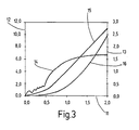
- the vehicle speed is plotted in km / h on the left vertical axis 12.
- the vehicle travel in m and the rotational speed of the crankshaft 7 in 1000 / min are plotted on the right vertical axis 13, and the time in sec is plotted on the horizontal axis 11.
- the characteristic curves of the crankshaft speeds are denoted by 14, the vehicle speeds by 15 and the distance covered by 16.
- FIG. 2 showing a conventional vehicle start of a vehicle with a starter generator is to be taken from the initially mentioned dead time, which is between the start of the starting operation, that is, the cranking of the crankshaft, and the beginning of the vehicle movement.
- this dead time is about 0.7 seconds.
- FIG. 3 shows the starting process of a vehicle which is equipped with a drive train according to the invention, wherein a sart-stop vehicle start is shown with starter generator and engaged gear.
Description
Die Erfindung betrifft einen Antriebsstrang für ein Kraftfahrzeug, mit den im Oberbegriff des Anspruchs 1 genannten Merkmalen.The invention relates to a drive train for a motor vehicle, with the features mentioned in the preamble of claim 1.
Um den Anlassvorgang eines Verbrennungsmotors zu verwirklichen, werden überwiegend elektrische Maschinen verwendet, wobei im Normalfall zum Anlassen des Verbrennungsmotors ein Starterritzel in die Schwungscheibenverzahnung eingespurt wird. Die zum Starten von Verbrennungsmotoren eingesetzten elektrischen Maschinen sind in der Regel Gleich-, Wechsel- oder Drehstrommotoren. Zunehmend an Bedeutung gewinnen jedoch auch elektrische Maschinen in Form von Startergeneratoren, die zum Anlassen des Verbrennungsmotors als Elektromotor und während des Betriebs des Verbrennungsmotors als Generator betrieben werden.In order to realize the starting process of an internal combustion engine, predominantly electrical machines are used, normally a starter pinion being meshed with the flywheel toothing for starting the internal combustion engine. The electrical machines used to start internal combustion engines are usually DC, AC or AC motors. However, electrical machines in the form of starter generators, which are operated to start the internal combustion engine as an electric motor and during operation of the internal combustion engine as a generator, are also becoming increasingly important.
Besonders als Startermotor geeignet ist der elektrische Gleichstrom-Reihenschlussmotor, da dieser das erforderliche hohe Anfangsdrehmoment zur Überwindung der Andrehwiderstände und zur Beschleunigung der Triebwerksmassen entwickelt. Dies ist erforderlich, weil bei jedem Startvorgang erhebliche Widerstände durch die Motorverdichtung, die Kolbenreibung und die Lagerreibung entgegengesetzt werden. Ferner spielen die Bauart sowie die Zylinderanzahl des Motors, das verwendete Schmiermittel und die aktuelle Motortemperatur eine wesentliche Rolle für den Startvorgang des Verbrennungsmotors.Particularly suitable as a starter motor is the electric DC series motor, since this develops the required high initial torque to overcome the starting resistance and to accelerate the engine masses. This is necessary because at each startup significant resistance by the engine compression, the piston friction and bearing friction are opposed. Furthermore, the design and the number of cylinders of the engine, the lubricant used and the current engine temperature play an essential role in the starting process of the internal combustion engine.
Überwiegend wird das Drehmoment des Starters über ein Ritzel und einen Zahnkranz auf das Schwungrad an der Kurbelwelle des Verbrennungsmotors übertragen. In vereinzelten Fällen werden aber auch Riemen, Keilriemen, Zahnriemen, Ketten oder die Direktübertragung auf die Kurbelwelle gewählt. Der Ritzelstarter ist jedoch wegen der großen Übersetzung zwischen Starterritzel und Zahnkranz der Motorschwungscheibe am besten für einen Startvorgang geeignet, da er auf ein niedriges Drehmoment bei hohen Drehzahlen ausgelegt werden kann. Diese Auslegung ermöglicht es, die Abmessungen und das Gewicht des Starters klein zu halten.Predominantly, the torque of the starter is transmitted via a pinion and a ring gear on the flywheel on the crankshaft of the internal combustion engine. Occasionally, however, belts, V-belts, timing belts, chains or direct transmission to the crankshaft are also selected. However, the pinion starter is best suited for a starting operation because of the large ratio between the starter pinion and ring gear of the engine flywheel, since it can be designed for low torque at high speeds. This design makes it possible to keep the dimensions and weight of the starter small.
Der Starter muss den Verbrennungsvorgang mit einer Mindestdrehzahl, die Startdrehzahl genannt wird, durchdrehen, damit auch bei ungünstigen Betriebsbedingungen das beim Ottomotor zum Selbstlauf notwendige Luft-Kraftstoff-Gemisch gebildet bzw. beim Dieselmotor die Selbstzündungstemperatur erreicht werden kann. Ferner muss der Starter den Verbrennungsmotor nach den ersten Zündungen beim Hochlaufen auf dessen Mindestselbstdrehzahl unterstützen.The starter must the combustion process with a minimum speed, the starting speed is called, spin, so even in unfavorable operating conditions necessary for the gasoline engine to self-run air-fuel mixture formed or the diesel engine, the autoignition temperature can be achieved. In addition, the starter must assist the engine after its first firings when running up to its minimum self-revving speed.
Insbesondere dann, wenn es sich um ein Fahrzeug mit Start-Stopp-Automatik handelt, muss der Verbrennungsmotor häufig gestartet werden.In particular, when it comes to a vehicle with automatic start-stop, the engine must be started frequently.
Erst wenn die Verbrennungsmaschine auf eine zur Leistungsabgabe ausreichende Drehzahl beschleunigt hat, kann die Kupplung geschlossen werden, und das Fahrzeug fährt an.Only when the internal combustion engine has accelerated to a sufficient speed for power output, the clutch can be closed, and the vehicle starts.
Wenn der Verbrennungsmotor an einer Ampel abgestellt wurde, ist das erneute Anlassen des Verbrennungsmotors besonders störend, da durch das Starten des Verbrennungsmotors eine Totzeit entsteht, bis sich das Fahrzeug in Bewegung setzt.If the internal combustion engine has been switched off at a traffic light, the restarting of the internal combustion engine is particularly disturbing, since the starting of the internal combustion engine causes a dead time until the vehicle starts to move.
Ein weiteres Problem kann beispielsweise dadurch auftreten, dass der Startvorgang bei Start-Stop-Systemen durch die Betätigung des Fahrpedals eingeleitet wird, das heißt, der Fahrer muss zur Betätigung des Fahrpedals den Fuß von der Bremse nehmen, um das Fahrzeug zu starten. Dies führt dazu, dass das Fahrzeug bei einem Halt im Gefälle während der Totzeit zurück rollen kann, falls der Fahrer die Handbremse nicht vorsorglich betätigt hat. Beim Anfahren muss der Fahrer die Handbremse dann im richtigen Moment lösen, damit der Verbrennungsmotor nicht gegen die Bremse arbeitet.Another problem may for example occur in that the startup procedure is initiated in start-stop systems by the operation of the accelerator pedal, that is, the driver must take his foot off the brake to actuate the accelerator pedal to start the vehicle. This means that the vehicle can roll back during a stop on the slope during the dead time, if the driver has not operated the handbrake as a precaution. When starting up, the driver then has to release the handbrake at the correct moment so that the internal combustion engine does not work against the brake.
Zur Lösung dieses Problems wurde bereits eine innerhalb des Getriebes angeordnete mechanische Vorrichtung vorgeschlagen, die ein Rollen des Fahrzeugs entgegen der gewünschten Fahrtrichtung, die am eingelegten Gang erkannt wird, verhindert.To solve this problem, a mechanical device arranged inside the transmission has already been proposed, which prevents rolling of the vehicle against the desired direction of travel, which is detected at the engaged gear.
Die
Die
Dadurch, dass bei dem erfindungsgemäßen Antriebsstrang für ein Kraftfahrzeug Mittel vorgesehen sind, die die Kupplung beim Start des Verbrennungsmotors derart betätigen können, dass ein erster Teil des beim Starten des Verbrennungsmotors von der elektrischen Maschine erzeugten Drehmoments auf das zumindest eine Fahrzeugantriebsrad und ein zum Starten des Verbrennungsmotors ausreichender zweiter Teil des von der elektrischen Maschine erzeugten Drehmoments auf den Verbrennungsmotor übertragen wird, können die vorstehend genannten Probleme beseitigt werden, ohne dass eine innerhalb des Getriebes angeordnete mechanische Vorrichtung erforderlich ist.Characterized in that in the drive train according to the invention for a motor vehicle means are provided which can actuate the clutch at the start of the engine so that a first part of the torque generated by the electric machine when starting the engine to the at least one vehicle drive and a to start the Engine sufficient second part of the torque generated by the electric machine is transmitted to the internal combustion engine, the above problems can be eliminated without a mechanical device disposed within the transmission is required.
Die Mittel umfassen in einer ersten Ausführungsform der Erfindung eine Steuerungseinrichtung, für die temperatur abhängige Kennfelder für das Startmoment und/oder für das vorwiegend vom Kupplungseinrückweg abhängige Kupplungsmoment verwendet werden.The means comprise in a first embodiment of the invention, a control device, are used for the temperature-dependent maps for the starting torque and / or for the predominantly dependent on the Kupplungseinrückweg clutch torque.
Die Mittel können auch eine Regelungsvorrichtung umfassen. Die Regelgröße des Regelungskreises kann beispielsweise durch die Kurbelwellendrehzahl gebildet sein. Die Führungsgröße, das heißt die Größe, deren Wert die Aufgabengröße unter festgelegten Bedingungen annehmen soll, kann in diesem Fall beispielsweise die Kurbelwellendrehzahl sein, ab der der Verbrennungsmotor Leistung abgeben kann. Das Stellglied kann beispielsweise durch einen Kupplungsautomaten gebildet sein.The means may also comprise a control device. The controlled variable of the control loop can be formed for example by the crankshaft speed. The reference variable, that is to say the quantity whose value the task variable should assume under specified conditions, can in this case be, for example, the crankshaft speed from which the internal combustion engine can deliver power. The Actuator can be formed for example by a coupling machine.
Die Regelungsvorrichtung kann das beim Starten des Verbrennungsmotors von der elektrischen Maschine auf das zumindest eine Fahrzeugantriebsrad übertragene Drehmoment derart regeln, dass Drehungleichförmigkeiten des Verbrennungsmotors beim Start des Verbrennungsmotors von dem zumindest einem Fahrzeugantriebsrad entkoppelt werden.The control device can regulate the torque transmitted to the at least one vehicle drive wheel by the electric machine when starting the internal combustion engine in such a way that rotational irregularities of the internal combustion engine are decoupled from the at least one vehicle drive wheel when starting the internal combustion engine.
Diese Entkopplung der Drehungleichförmigkeiten kann zumindest solange erfolgen, bis der Verbrennungsmotor eine Drehzahl erreicht hat, bei der er Leistung abgeben kann. Weiterhin ist es denkbar, dass die Regelungsvorrichtung das beim Starten des Verbrennungsmotors von der elektrischen Maschine auf das zumindest eine Fahrzeugantriebsrad übertragene Drehmoment derart regelt, dass das Fahrzeug im Stillstand gehalten wird, bis der Verbrennungsmotor eine Drehzahl erreicht hat, bei der er Leistung abgeben kann.This decoupling of the rotational irregularities can take place at least until the internal combustion engine has reached a speed at which it can deliver power. Furthermore, it is conceivable that the control device regulates the torque transmitted by the electric machine to the at least one vehicle drive wheel during starting of the internal combustion engine such that the vehicle is held stationary until the internal combustion engine has reached a speed at which it can deliver power.
Durch eine derartige Regelung würde zwar ein Zurückrollen des Fahrzeugs aufgrund eines Gefälles vermieden, die anfangs erwähnte Totzeit jedoch nicht beseitigt.Such a regulation would indeed prevent rolling back of the vehicle due to a gradient, but does not eliminate the initially mentioned dead time.
Unabhängig von der speziell gewählten Regelung sind gemäß einer weiteren Ausführungsform der Erfindung Sensoren vorgesehen, die einen Ausnahmezustand erfassen, in dem sich das Fahrzeug aufgrund von äußeren Kräften ungewollt in Bewegung setzen würde, weil das beim Starten er elektrischen Maschine auf das zumindest eine Fahrzeugantriebsrad übertragene Drehmoment zu klein ist, um die ungewollte Bewegung des Kraftfahrzeugs zu verhindern.Regardless of the specially selected control sensors are provided according to a further embodiment, which detect a state of emergency in which the vehicle would unintentionally set in motion due to external forces, because at the start he electric machine transmitted to the at least one vehicle drive torque too small to prevent the unwanted movement of the motor vehicle.
Die erfindungsgemäßen äußeren Kräfte umfassen beispielsweise die Erdanziehungskraft, die beim Anfahren im Gefälle zu einer ungewollten Bewegung der Kraftfahrzeugs führen kann.The external forces according to the invention include, for example, the gravitational force, which can lead to an unwanted movement of the motor vehicle when starting on a gradient.
Es ist denkbar, dass der von den Sensoren erfasste Ausnahmezustand dem Fahrer auf irgendeine geeignete Weise angezeigt wird, beispielsweise optisch und/oder akustisch und/oder haptisch.It is conceivable that the state of emergency detected by the sensors is displayed to the driver in any suitable manner, for example optically and / or acoustically and / or haptically.
Gemäß dieser Ausführungsform ist eine Fahrzeugbremse vorgesehen, die beim Auftreten des Ausnahmezustandes automatisch betätigt wird, um die ungewollte Bewegung des Kraftfahrzeuges zu verhindern.According to this embodiment, a vehicle brake is provided, which is automatically actuated when the state of emergency occurs to prevent the unwanted movement of the motor vehicle.
Diese Fahrzeugbremse ist vorzugsweise die ohnehin vorgesehene Feststellbremse oder die an das übliche Bremssystem angeschlossene Bremse.This vehicle brake is preferably the parking brake provided anyway or the brake connected to the conventional brake system.
In diesem Fall ist es vorteilhaft, wenn die Fahrzeugbremse automatisch gelöst wird, wenn der Verbrennungsmotor eine Drehzahl erreicht hat, bei der er Leistung abgeben kann, das heißt, in einem Zustand, in dem sich das Fahrzeug in der gewünschten Richtung in Bewegung setzen kann.In this case, it is advantageous if the vehicle brake is automatically released when the engine has reached a speed at which it can output power, that is, in a state in which the vehicle can start moving in the desired direction.
Weiterhin ist es denkbar, dass die Regelungsvorrichtung das beim Starten des Verbrennungsmotors von der elektrischen Maschine auf das zumindest eine Fahrzeugantriebsrad übertragene Drehmoment derart regelt, dass sich das Fahrzeug in Bewegung setzt, bevor der Verbrennungsmotor eine Drehzahl erreicht hat, bei der er Leistung abgeben kann.Furthermore, it is conceivable for the control device to regulate the torque transmitted by the electric machine to the at least one vehicle drive wheel when starting the internal combustion engine in such a way that the vehicle starts to move before the internal combustion engine has reached a speed at which it can output power.
Bei dieser Regelungsvariante können sowohl ein ungewolltes Zurückrollen als auch die anfangs erwähnte Totzeit vermieden werden, weil das Kraftfahrzeug bereits durch das von der elektrischen Maschine erzeugte Drehmoment in Bewegung setzen kann.In this control variant both an unintentional rollback and the initially mentioned dead time can be avoided because the motor vehicle can already set in motion by the torque generated by the electric machine.
Die erfindungsgemäß vorgesehenen Mittel umfassen vorzugsweise einen Kuoplungsautomaten, der die Kupplung betätigt.The inventively provided means preferably comprise a Kuoplungsautomaten that operates the clutch.
In diesem Fall kann die Regelungsvorrichtung den Kupplungsautomaten ansteuern.In this case, the control device can control the automatic coupling.
Die durch die vorliegende Erfindung erzielten Vorteile wirken sich insbesondere dann aus, wenn es sich um ein Kraftfahrzeug handelt, bei dem eine Start-Stopp-Automatik vorgesehen ist, die den Verbrennungsmotor bei einem Stillstand des Fahrzeugs, beispielsweise an einer roten Ampel, abstellen und zur Weiterfahrt wieder starten kann.The advantages achieved by the present invention have particular effect if it is a motor vehicle, in which an automatic start-stop system is provided, which shut off the engine when the vehicle is at a standstill, for example at a red traffic light, and for Continue driving can start again.
Es kann vorteilhaft sein, dass nur beim Start-Stop-Betrieb des Fahrzeugs, nicht jedoch beim bezogen auf die Fahrt ersten Startvorgang, der erste Teil des beim Starten von der elektrischen Maschine erzeugten Drehmoments auf das zumindest eine Antriebsrad übertragen wird.It may be advantageous that only during the start-stop operation of the vehicle, but not in relation to the first drive start operation, the first part of the torque generated during the start of the electric machine is transmitted to the at least one drive wheel.
Die elektrische Maschine kann entweder ein (ausschließlicher) Starter oder ein sogenannter Startergenerator sein, der beim Start des Verbrennungsmotors als Elektromotor und bei laufendem Verbrennungsmotor als Generator betrieben wird.The electric machine can either be an (exclusive) starter or a so-called starter generator, which is operated as an electric motor when starting the internal combustion engine and as a generator when the internal combustion engine is running.
Die Erfindung wird nachfolgend anhand der zugehörigen Zeichnungen näher erläutert.The invention will be explained in more detail with reference to the accompanying drawings.
Es zeigen:
- Figur 1
- eine prinzipielle Anordnung einer Ausführungsform des erfindungsgemäßen Antriebsstranges;
Figur 2- den Zusammenhang zwischen Kurbelwellendrehzahl, Fahrzeuggeschwindigkeit und zurückgelegtem Weg, für ein Fahrzeug, das einen herkömmlichen Antriebsstrang aufweist; und
Figur 3- den Zusammenhang zwischen Kurbelwellendrehzahl, Fahrzeuggeschwindigkeit und zurückgelegtem weg, für ein Fahrzeug, das mit einem erfindungsgemäßen Antriebsstrang ausgestattet ist.
- FIG. 1
- a basic arrangement of an embodiment of the drive train according to the invention;
- FIG. 2
- the relationship between crankshaft speed, vehicle speed, and distance traveled for a vehicle having a conventional powertrain; and
- FIG. 3
- the relationship between crankshaft speed, vehicle speed and distance traveled, for a vehicle that is equipped with a drive train according to the invention.
In
In diese Außenverzahnung greift, zumindest beim Startvorgang, das Starterritzel eines Starters 2 ein.At least during the starting process, the starter pinion of a
Weiterhin ist eine hier nicht näher interessierende Lichtmaschine 9 angedeutet, die über einen Keilriemen 10 ebenfalls mit der Kurbelwelle 7 verbunden ist.Furthermore, an here not closer interest generator 9 is indicated, which is also connected via a V-
Der dargestellte Antriebsstrang umfasst weiterhin eine Kupplung 3, die zwischen dem Verbrennungsmotor 1 und einem Getriebe 4 angeordnet ist, über das ein durch den Verbrennungsmotor erzeugtes Drehmoment auf zumindest ein nicht dargestelltes Fahrzeugantriebsrad übertragen werden kann. Die Mittel, die die Kupplung 3 beim Start des Verbrennungsmotors 1 derart betätigen können, dass ein erster Teil des beim Starten des Verbrennungsmotors von der elektrischen Maschine (in Form eines Starters 2) erzeugten Drehmoments auf das zumindest eine Fahrzeugantriebsrad und ein zum Starten des Verbrennungsmotors 1 ausreichender zweiter Teil des vom Starter 2 erzeugten Drehmoments auf den Verbrennungsmotor 1 übertragen wird, sind im dargestellten Fall durch eine Regelungsvorrichtung 5 und einen Kupplungsautomaten 6 gebildet.The illustrated powertrain further comprises a clutch 3, which is arranged between the internal combustion engine 1 and a
Im dargestellten Fall ist die Startanlage des Verbrennungsmotors 1 derart dimensioniert, dass auch bei extrem tiefen Temperaturen ein sicherer Start möglich ist.In the case shown, the starting system of the internal combustion engine 1 is dimensioned such that a safe start is possible even at extremely low temperatures.
Wenn eine Start-Stopp-Automatik vorgesehen ist, erfolgt der Wiederholstart bei betriebswarmem Verbrennungsmotor 1, der wesentlich weniger Startleistung erfordert, als der noch nicht auf Betriebstemperatur gebrachte Verbrennungsmotor 1.If an automatic start-stop system is provided, the restarting start takes place with the internal combustion engine 1 at operating temperature, which requires substantially less starting power than the internal combustion engine 1, which has not yet been brought to operating temperature.
Diese Überschussleistung der Startanlage kann dazu genutzt werden, das Fahrzeug am Rollen in eine nicht gewünschte Richtung zu hindern und/oder dazu, das Fahrzeug schon während des Starts in Bewegung zu setzen, um den Nachteil der oben beschriebenen Totzeit zu vermeiden.This surplus power of the starting system can be used to prevent the vehicle from rolling in an undesired direction and / or to set the vehicle in motion during the start in order to avoid the disadvantage of the dead time described above.
Die Regelung des Systems erfolgt über die Beschränkung des Anfahrmoments derart, dass Drehungleichförmigkeiten des Verbrennungsmotors bei seinem Start und beim Hochlaufen vom übrigen Antriebsstrang entkoppelt und unvorhersehbare Fahrzeugbeschleunigungen vermieden werden.The system is controlled by limiting the starting torque in such a way that rotational irregularities of the internal combustion engine are decoupled from the rest of the drive train at its start and during run-up and unpredictable vehicle accelerations are avoided.
Das Kraftfahrzeug wird in der Stillstandsphase über die Kupplung 3 und einen eingelegten Gang gehalten.The motor vehicle is held in the standstill phase via the
Beim dargestellten Ausführungsbeispiel regelt die Regelungsvorrichtung 5 das beim Starten des Verbrennungsmotors 1 von der elektrischen Maschine 2 auf das zumindest eine Fahrzeugantriebsrad übertragene Drehmoment derart, dass sich das Kraftfahrzeug 1 in Bewegung setzt, bevor der Verbrennungsmotor 1 eine Drehzahl erreicht hat, bei der er Leistung abgeben kann. Anders ausgedrückt, überschneiden sich der Hochlauf des Verbrennungsmotors 1 und der Beschleunigungsvorgang des Fahrzeugs, wodurch die Totzeit beim Anfahren beseitigt oder zumindest erheblich reduziert wird. An Steigungen sind in der Regel keine zusätzlichen Eingriffe des Fahrers erforderlich.In the illustrated embodiment, the
Beim Start des Verbrennungsmotors 1 wird die Kupplung 3 vom Kupplungsautomaten 6 soweit betätigt, dass das übertragbare Drehmoment ausreicht, um das Fahrzeug zu halten bzw. leicht zu beschleunigen. Ist die erforderliche Drehzahl des Verbrennungsmotors 1 für eine Leistungsabgabe erreicht, wird die Kupplung 3 weiter geschlossen und das Kraftfahrzeug beschleunigt. In der Ebene oder bei leichten Steigungen reicht der Minimalwert der Wechselmomente des Verbrennungsmotors 1 aus.When starting the engine 1, the
Obwohl dies nicht näher dargestellt ist, ist es denkbar, anstelle eines herkömmlichen Starters leistungsstärkere Systeme mit kleinerer Übersetzung zur Kurbelwelle zu verwenden. Derartige leistungsstärkere Systeme würden eine noch bessere Hochlaufunterstützung und damit eine volle Überschneidung des Starts und der Beschleunigung des Fahrzeugs gewährleisten.Although not shown in detail, it is conceivable to use more powerful systems with a smaller crankshaft ratio instead of a conventional starter. Such more powerful systems would provide even better run-up assistance and thus full overlap of the vehicle's take-off and acceleration.
In den
In den
Dadurch, dass ein Teil des durch die elektrische Maschine 2 erzeugten Drehmoments vom Zeitpunkt des Andrehens der Kurbelwelle an auf zumindest ein Fahrzeugantriebsrad übertragen wird, entfällt die Totzeit, was insbesondere bei Fahrzeugen mit Start-Stopp-Automatik einen großen Vorteil darstellt.The fact that a part of the torque generated by the
Claims (20)
- Drive train for a motor vehicle, having an internal combustion engine (1), having an electric machine (2) which generates a torque when the internal combustion engine (1) starts, and having a clutch (3) which is arranged between the internal combustion engine (1) and a gearbox (4), by means of which gear box (4) a torque which is generated by means of the internal combustion engine (1) can be transmitted to at least one vehicle drive wheel, characterized in that means (5, 6) are provided which can activate the clutch (3) when the internal combustion engine starts in such a way that a first part of the torque which is generated by the electric machine (2) when the internal combustion engine starts is transmitted to the at least one vehicle drive wheel, and a second part of the torque which is generated by the electric machine (2) and which is sufficient to start the internal combustion engine (1) is transmitted to the internal combustion engine (1), wherein the means comprise a control device (5), and temperature-dependent characteristic diagrams for the starting torque and/or for the coupling torque which is mainly dependent on the engagement travel of the clutch are used for the control device (5).
- Drive train for a motor vehicle, having an internal combustion engine (1), having an electric machine (2) which generates a torque when the internal combustion engine (1) starts, and having a clutch (3) which is arranged between the internal combustion engine (1) and a gearbox (4), by means of which gear box (4) a torque which is generated by means of the internal combustion engine (1) can be transmitted to at least one vehicle drive wheel, characterized in that means (5, 6) are provided which can activate the clutch (3) when the internal combustion engine starts in such a way that a first part of the torque which is generated by the electric machine (2) when the internal combustion engine starts is transmitted to the at least one vehicle drive wheel, and a second part of the torque which is generated by the electric machine (2) and which is sufficient to start the internal combustion engine (1) is transmitted to the internal combustion engine (1), wherein sensors are provided which sense an exceptional state in which the motor vehicle would undesirably begin to move owing to external forces because the torque which is transmitted to the at least one vehicle drive wheel when the electric machine starts is too small to prevent the undesirable movement of the motor vehicle, and a vehicle brake is provided which is actuated automatically when the exceptional state occurs.
- Drive train according to Claim 2, characterized in that the means comprise a control device (5).
- Drive train according to Claim 1 or 3, characterized in that temperature-dependent and/or rotational-speed-dependent characteristic diagrams for the drive torque of the internal combustion engine (1) and/or for the starting torque and/or for the coupling torque which is mainly dependent on the engagement travel of the clutch are used for the control device (5).
- Drive train according to Claim 1 or 4, characterized in that the characteristic diagrams are changed adaptively.
- Drive train according to one of the preceding claims, characterized in that the means comprise a closed-loop control device (5).
- Drive train according to one of the preceding claims, characterized in that the closed-loop control device controls the torque which is transmitted to the at least one vehicle drive wheel by the electric machine (2) when the internal combustion engine (1) starts in such a way that rotation irregularities of the internal combustion engine (1) are decoupled from the at least one vehicle drive wheel when the internal combustion engine (1) starts.
- Drive train according to one of the preceding claims, characterized in that the rotational irregularities are decoupled at least until the internal combustion engine (1) has reached a rotational speed at which it can output power.
- Drive train according to one of the preceding claims, characterized in that the closed-loop control device (5) controls the torque which is transmitted to the at least one vehicle drive wheel by the electric machine (2) when the internal combustion engine (1) starts in such a way that the motor vehicle is kept in the stationary state until the internal combustion engine (1) has reached a rotational speed at which it can output power.
- Drive train according to Claim 1, characterized in that sensors are provided which sense an exceptional state in which the motor vehicle would undesirably begin to move owing to external forces because the torque which is transmitted to the at least one vehicle drive wheel when the electric machine starts is too small to prevent the undesirable movement of the motor vehicle.
- Drive train according to Claim 10, characterized in that the exceptional state which is sensed by the sensors is indicated to the driver.
- Drive train according to Claim 10, characterized in that a vehicle brake is provided which is actuated automatically when the exceptional state occurs.
- Drive train according to one of the preceding claims, characterized in that the vehicle brake is released automatically when the internal combustion engine (1) has reached a rotational speed at which it can output power.
- Drive train according to one of the preceding claims, characterized in that the closed-loop control device (5) controls the torque which is transmitted to the at least one vehicle drive wheel by the electric machine (2) when the internal combustion engine (1) starts in such a way that the motor vehicle begins to move before the internal combustion engine (1) has reached a rotational speed at which it can output power.
- Drive train according to one of the preceding claims, characterized in that the means comprise an automatic clutch actuator (6) which activates the clutch (3).
- Drive train according to one of the preceding claims, characterized in that the closed-loop control device (5) actuates the automatic clutch actuator (6).
- Drive train according to one of the preceding claims, characterized in that a start/stop automatic actuator is provided which can shut down the internal combustion engine when the motor vehicle is in a stationary state and can start it up again for further travel.
- Drive train according to one of the preceding claims, characterized in that the first part of the torque which is generated by the electric machine (2) when starting occurs is transmitted to the at least one drive wheel only in the start/stop operating mode of the motor vehicle, but not during the first starting process for the journey.
- Drive train according to one of the preceding claims, characterized in that the electric machine (2) is a starter.
- Drive train according to one of the preceding claims, characterized in that the electric machine (2) is a starter-generator.
Applications Claiming Priority (3)
| Application Number | Priority Date | Filing Date | Title |
|---|---|---|---|
| DE10007957 | 2000-02-22 | ||
| DE10007957 | 2000-02-22 | ||
| PCT/DE2000/004657 WO2001063122A1 (en) | 2000-02-22 | 2000-12-23 | Drivetrain for a motor vehicle |
Publications (3)
| Publication Number | Publication Date |
|---|---|
| EP1173674A1 EP1173674A1 (en) | 2002-01-23 |
| EP1173674B1 EP1173674B1 (en) | 2005-03-23 |
| EP1173674B2 true EP1173674B2 (en) | 2010-03-17 |
Family
ID=7631785
Family Applications (1)
| Application Number | Title | Priority Date | Filing Date |
|---|---|---|---|
| EP00991776A Expired - Lifetime EP1173674B2 (en) | 2000-02-22 | 2000-12-23 | Drive train for a motor vehicle |
Country Status (5)
| Country | Link |
|---|---|
| US (1) | US6830118B2 (en) |
| EP (1) | EP1173674B2 (en) |
| JP (2) | JP4460813B2 (en) |
| DE (1) | DE50009869D1 (en) |
| WO (1) | WO2001063122A1 (en) |
Families Citing this family (14)
| Publication number | Priority date | Publication date | Assignee | Title |
|---|---|---|---|---|
| SE524033C2 (en) * | 2002-10-16 | 2004-06-15 | Volvo Lastvagnar Ab | Automatic switch-on / switch-off procedure of a switch-independent power take-off |
| FR2858026B1 (en) * | 2003-07-24 | 2006-01-13 | Peugeot Citroen Automobiles Sa | METHOD FOR MANAGING INTERNAL COMBUSTION ENGINE |
| DE102006022395B4 (en) * | 2006-05-12 | 2015-03-05 | Robert Bosch Gmbh | Method for starting an internal combustion engine in a hybrid drive |
| DE102006036445A1 (en) | 2006-08-04 | 2008-05-15 | Robert Bosch Gmbh | Vacuum generation in hybrid-powered vehicles |
| DE102007061730A1 (en) | 2007-12-20 | 2009-06-25 | Robert Bosch Gmbh | Method and device for determining and predicting a starting torque or starting torque curve necessary for starting an internal combustion engine |
| DE102009004023B4 (en) * | 2009-01-08 | 2018-07-12 | Knorr-Bremse Systeme für Nutzfahrzeuge GmbH | A method for controlling a start-stop operation of a hybrid drive vehicle and a corresponding vehicle |
| US20110079454A1 (en) * | 2009-10-07 | 2011-04-07 | Gm Global Technology Operations, Inc. | Hybrid vehicle configuration and method of reconfiguring non-hybrid vehicle architecture as hybrid vehicle architecture |
| DE102011104395A1 (en) * | 2011-06-17 | 2012-12-20 | Audi Ag | Method for accelerating a vehicle and hybrid vehicle |
| US9481236B2 (en) | 2014-03-13 | 2016-11-01 | GM Global Technology Operations LLC | Powertrain for a vehicle |
| US9302575B2 (en) * | 2014-03-13 | 2016-04-05 | GM Global Technology Operations LLC | Powertrain for a vehicle and a method of assembling the powertrain |
| US9657705B2 (en) * | 2014-03-13 | 2017-05-23 | GM Global Technology Operations LLC | Powertrain for a vehicle and an electromechanical apparatus coupleable to an engine |
| DE102016222761A1 (en) | 2016-11-18 | 2018-05-24 | Schaeffler Technologies AG & Co. KG | Claw clutch for performing a pulse start for a motor vehicle with a hybrid drive |
| DE102017205490A1 (en) | 2017-03-31 | 2018-10-04 | Robert Bosch Gmbh | Method and device for vibration compensation of a torque acting on a shaft |
| DE102017205489A1 (en) | 2017-03-31 | 2018-10-04 | Robert Bosch Gmbh | Method and device for vibration compensation of a torque acting on a shaft |
Family Cites Families (20)
| Publication number | Priority date | Publication date | Assignee | Title |
|---|---|---|---|---|
| JPS5835245A (en) * | 1981-08-25 | 1983-03-01 | Toyota Motor Corp | Automatically stopping and restarting device of engine |
| JPS59160858A (en) * | 1983-03-01 | 1984-09-11 | Victor Co Of Japan Ltd | Setting device for tape storage housing |
| JPH045129U (en) * | 1990-04-27 | 1992-01-17 | ||
| DE19532135A1 (en) * | 1995-08-31 | 1997-03-06 | Clouth Gummiwerke Ag | Drive system, in particular for a motor vehicle, and method for operating the same |
| EP0848159B1 (en) | 1996-12-16 | 2002-07-10 | Robert Bosch Gmbh | Starting device for an internal combustion engine |
| JP3498509B2 (en) * | 1996-12-26 | 2004-02-16 | トヨタ自動車株式会社 | Hybrid vehicle control device |
| JP3454133B2 (en) * | 1998-01-16 | 2003-10-06 | トヨタ自動車株式会社 | Drive control device for hybrid vehicle |
| JP3706732B2 (en) * | 1998-03-17 | 2005-10-19 | 本田技研工業株式会社 | Vehicle engine stop control device |
| JP3671669B2 (en) * | 1998-04-13 | 2005-07-13 | アイシン・エィ・ダブリュ株式会社 | Creep travel control device for hybrid vehicle |
| US6209672B1 (en) * | 1998-09-14 | 2001-04-03 | Paice Corporation | Hybrid vehicle |
| JP2001099039A (en) * | 1999-09-30 | 2001-04-10 | Suzuki Motor Corp | Control device of engine-connected type motor |
| JP3649058B2 (en) * | 1999-10-08 | 2005-05-18 | トヨタ自動車株式会社 | Vehicle control apparatus having a plurality of prime movers |
| KR100369135B1 (en) * | 1999-12-28 | 2003-01-24 | 현대자동차주식회사 | Power transmit apparatus for hybrid electric vehicle |
| US6376927B1 (en) * | 2000-01-18 | 2002-04-23 | Saturn Corporation | Hybrid electric drive and control method therefor |
| US6484833B1 (en) * | 2000-03-17 | 2002-11-26 | General Motors Corporation | Apparatus and method for maintaining state of charge in vehicle operations |
| US6394208B1 (en) * | 2000-03-30 | 2002-05-28 | Ford Global Technologies, Inc. | Starter/alternator control strategy to enhance driveability of a low storage requirement hybrid electric vehicle |
| JP3820842B2 (en) * | 2000-04-05 | 2006-09-13 | スズキ株式会社 | Control device for hybrid vehicle |
| US6585066B1 (en) * | 2000-05-09 | 2003-07-01 | Ford Global Technologies, Llc | Motor/alternator with integral wet clutch for use in hybrid vehicles |
| JP3651772B2 (en) * | 2000-08-04 | 2005-05-25 | スズキ株式会社 | Control device for hybrid vehicle |
| US6600980B1 (en) * | 2002-09-26 | 2003-07-29 | Ford Global Technologies, Llc | Torque reversal reduction strategy for a hybrid vehicle |
-
2000
- 2000-12-23 WO PCT/DE2000/004657 patent/WO2001063122A1/en active IP Right Grant
- 2000-12-23 US US10/030,871 patent/US6830118B2/en not_active Expired - Lifetime
- 2000-12-23 DE DE50009869T patent/DE50009869D1/en not_active Expired - Lifetime
- 2000-12-23 JP JP2001561911A patent/JP4460813B2/en not_active Expired - Lifetime
- 2000-12-23 EP EP00991776A patent/EP1173674B2/en not_active Expired - Lifetime
-
2009
- 2009-03-16 JP JP2009063366A patent/JP4971382B2/en not_active Expired - Lifetime
Also Published As
| Publication number | Publication date |
|---|---|
| JP2009133494A (en) | 2009-06-18 |
| DE50009869D1 (en) | 2005-04-28 |
| JP4460813B2 (en) | 2010-05-12 |
| JP2003524113A (en) | 2003-08-12 |
| EP1173674A1 (en) | 2002-01-23 |
| EP1173674B1 (en) | 2005-03-23 |
| WO2001063122A1 (en) | 2001-08-30 |
| US6830118B2 (en) | 2004-12-14 |
| JP4971382B2 (en) | 2012-07-11 |
| US20030102173A1 (en) | 2003-06-05 |
Similar Documents
| Publication | Publication Date | Title |
|---|---|---|
| DE102007012046B4 (en) | Control unit for a hybrid electric vehicle | |
| EP1807278B1 (en) | Method for controlling deceleration of a hybrid vehicle and hybrid vehicle | |
| DE2748697C2 (en) | Drive arrangement for a vehicle, in particular a passenger vehicle | |
| EP1173674B2 (en) | Drive train for a motor vehicle | |
| EP3668737B1 (en) | Hybrid drive transmission unit and method for operating a vehicle with a hybrid drive | |
| EP2884083B1 (en) | Methods for starting a combustion engine of a motor vehicle and motor vehicle | |
| WO2007099003A1 (en) | Hybrid drive having a separating clutch which assists a direct start | |
| WO2005110793A1 (en) | Method and device for stopping and starting the motor of hybrid vehicles | |
| EP1046811B1 (en) | Electric drive apparatus for internal combustion engines in vehicles | |
| EP1870273B1 (en) | Hybrid vehicle | |
| EP1113169A1 (en) | Starter device for an internal combustion engine and method for controlling the same | |
| DE102006034937A1 (en) | Hybrid drive`s i.e. passenger car, drive train operating procedure, involves increasing torque that is introduced into drive section by electric motor, such that current desired torque is introduced into gear box input | |
| DE3016620A1 (en) | DRIVE UNIT | |
| WO2010057746A1 (en) | Method and device for operating a hybrid drive for a vehicle | |
| WO2014195089A1 (en) | Method for performing open-loop and/or closed-loop control of a hybrid drive arrangement of a motor vehicle | |
| DE102016202138A1 (en) | Method for starting an internal combustion engine and drive train for a motor vehicle | |
| WO2005110794A1 (en) | Method for operating a hybrid motor vehicle | |
| EP2289752A2 (en) | Method for operating a drive train | |
| DE112012004086T5 (en) | Control device and control method of a hybrid electric vehicle | |
| DE102008013411A1 (en) | Motor vehicle operating method, involves triggering stop process for internal-combustion engine, detecting terminating condition during stop process by start-stop-control unit, and canceling stop process when terminating condition exists | |
| DE102011087943A1 (en) | Control device of a hybrid vehicle and method for operating the same | |
| DE3019273A1 (en) | DRIVE UNIT, ESPECIALLY FOR MOTOR VEHICLES | |
| EP3351446B1 (en) | Method for operating a drive device for a motor vehicle and corresponding drive device | |
| AT413806B (en) | Method for reducing transmission noises of drive train of vehicle e.g. small size car, involves controlling torque in drive train such that drive oscillations are suppressed depending on tensile or axial load in transfer box | |
| AT412861B (en) | Motor vehicle e.g. small-size car, start-up phase controlling method, involves starting fuel injection process at time after synchronization time, where time of start of clutch lies before synchronization time |
Legal Events
| Date | Code | Title | Description |
|---|---|---|---|
| PUAI | Public reference made under article 153(3) epc to a published international application that has entered the european phase |
Free format text: ORIGINAL CODE: 0009012 |
|
| AK | Designated contracting states |
Kind code of ref document: A1 Designated state(s): AT BE CH CY DE DK ES FI FR GB GR IE IT LI LU MC NL PT SE TR |
|
| AX | Request for extension of the european patent |
Free format text: AL;LT;LV;MK;RO;SI |
|
| 17P | Request for examination filed |
Effective date: 20020228 |
|
| RBV | Designated contracting states (corrected) |
Designated state(s): DE FR GB IT |
|
| GRAP | Despatch of communication of intention to grant a patent |
Free format text: ORIGINAL CODE: EPIDOSNIGR1 |
|
| GRAS | Grant fee paid |
Free format text: ORIGINAL CODE: EPIDOSNIGR3 |
|
| GRAA | (expected) grant |
Free format text: ORIGINAL CODE: 0009210 |
|
| AK | Designated contracting states |
Kind code of ref document: B1 Designated state(s): DE FR GB IT |
|
| REG | Reference to a national code |
Ref country code: GB Ref legal event code: FG4D Free format text: NOT ENGLISH |
|
| REG | Reference to a national code |
Ref country code: IE Ref legal event code: FG4D Free format text: GERMAN |
|
| REF | Corresponds to: |
Ref document number: 50009869 Country of ref document: DE Date of ref document: 20050428 Kind code of ref document: P |
|
| GBT | Gb: translation of ep patent filed (gb section 77(6)(a)/1977) |
Effective date: 20050718 |
|
| PLBI | Opposition filed |
Free format text: ORIGINAL CODE: 0009260 |
|
| PLAX | Notice of opposition and request to file observation + time limit sent |
Free format text: ORIGINAL CODE: EPIDOSNOBS2 |
|
| 26 | Opposition filed |
Opponent name: CONTI TEMIC MICROELECTRONIC GMBH Effective date: 20051210 |
|
| ET | Fr: translation filed | ||
| PLAB | Opposition data, opponent's data or that of the opponent's representative modified |
Free format text: ORIGINAL CODE: 0009299OPPO |
|
| R26 | Opposition filed (corrected) |
Opponent name: CONTI TEMIC MICROELECTRONIC GMBH Effective date: 20051210 |
|
| PLAB | Opposition data, opponent's data or that of the opponent's representative modified |
Free format text: ORIGINAL CODE: 0009299OPPO |
|
| R26 | Opposition filed (corrected) |
Opponent name: CONTI TEMIC MICROELECTRONIC GMBH Effective date: 20051210 |
|
| APBP | Date of receipt of notice of appeal recorded |
Free format text: ORIGINAL CODE: EPIDOSNNOA2O |
|
| APAH | Appeal reference modified |
Free format text: ORIGINAL CODE: EPIDOSCREFNO |
|
| APBQ | Date of receipt of statement of grounds of appeal recorded |
Free format text: ORIGINAL CODE: EPIDOSNNOA3O |
|
| PLAB | Opposition data, opponent's data or that of the opponent's representative modified |
Free format text: ORIGINAL CODE: 0009299OPPO |
|
| R26 | Opposition filed (corrected) |
Opponent name: CONTI TEMIC MICROELECTRONIC GMBH Effective date: 20051210 |
|
| APBU | Appeal procedure closed |
Free format text: ORIGINAL CODE: EPIDOSNNOA9O |
|
| PUAH | Patent maintained in amended form |
Free format text: ORIGINAL CODE: 0009272 |
|
| STAA | Information on the status of an ep patent application or granted ep patent |
Free format text: STATUS: PATENT MAINTAINED AS AMENDED |
|
| 27A | Patent maintained in amended form |
Effective date: 20100317 |
|
| AK | Designated contracting states |
Kind code of ref document: B2 Designated state(s): DE FR GB IT |
|
| REG | Reference to a national code |
Ref country code: FR Ref legal event code: PLFP Year of fee payment: 16 |
|
| REG | Reference to a national code |
Ref country code: FR Ref legal event code: PLFP Year of fee payment: 17 |
|
| REG | Reference to a national code |
Ref country code: FR Ref legal event code: PLFP Year of fee payment: 18 |
|
| PGFP | Annual fee paid to national office [announced via postgrant information from national office to epo] |
Ref country code: IT Payment date: 20191216 Year of fee payment: 20 Ref country code: FR Payment date: 20191219 Year of fee payment: 20 |
|
| PGFP | Annual fee paid to national office [announced via postgrant information from national office to epo] |
Ref country code: DE Payment date: 20200221 Year of fee payment: 20 Ref country code: GB Payment date: 20191220 Year of fee payment: 20 |
|
| REG | Reference to a national code |
Ref country code: DE Ref legal event code: R071 Ref document number: 50009869 Country of ref document: DE |
|
| REG | Reference to a national code |
Ref country code: GB Ref legal event code: PE20 Expiry date: 20201222 |
|
| PG25 | Lapsed in a contracting state [announced via postgrant information from national office to epo] |
Ref country code: GB Free format text: LAPSE BECAUSE OF EXPIRATION OF PROTECTION Effective date: 20201222 |