EP1173005A2 - Method and apparatus for color image data processing and compression - Google Patents
Method and apparatus for color image data processing and compression Download PDFInfo
- Publication number
- EP1173005A2 EP1173005A2 EP00311101A EP00311101A EP1173005A2 EP 1173005 A2 EP1173005 A2 EP 1173005A2 EP 00311101 A EP00311101 A EP 00311101A EP 00311101 A EP00311101 A EP 00311101A EP 1173005 A2 EP1173005 A2 EP 1173005A2
- Authority
- EP
- European Patent Office
- Prior art keywords
- color image
- pattern
- color
- image pattern
- data
- Prior art date
- Legal status (The legal status is an assumption and is not a legal conclusion. Google has not performed a legal analysis and makes no representation as to the accuracy of the status listed.)
- Granted
Links
Images


Classifications
-
- H—ELECTRICITY
- H04—ELECTRIC COMMUNICATION TECHNIQUE
- H04N—PICTORIAL COMMUNICATION, e.g. TELEVISION
- H04N1/00—Scanning, transmission or reproduction of documents or the like, e.g. facsimile transmission; Details thereof
- H04N1/46—Colour picture communication systems
- H04N1/64—Systems for the transmission or the storage of the colour picture signal; Details therefor, e.g. coding or decoding means therefor
Definitions
- the present invention relates generally to imaging methods and devices, and in particular relates to a method and apparatus for processing and compressing color images by color image sensor devices.
- RGB Joint Photographic Experts Group
- Current methods of color image or video compression usually process data in a fully interpolated color space.
- these color spaces include the YUV space having a 4:2:2 ratio (where Y is a luminance component, and U and V are chrominance components or color difference components) and YC b C r space (where Y is a luminance component, C b is a chrominance-blue component, and C, is a chrominance-red component).
- YUV space having a 4:2:2 ratio where Y is a luminance component, and U and V are chrominance components or color difference components
- YC b C r space where Y is a luminance component, C b is a chrominance-blue component, and C, is a chrominance-red component.
- Data is processed in these spaces because a standard raw data stream, such as data in a Bayer pattern, is much more difficult to compress.
- RGB Red, Green, Blue
- FIG. 1 shows a flow diagram 10 illustrating this procedure.
- RGB raw data at a block 12 is preprocessed at an interpolation block 14 that interpolates the RGB raw data into a YC b C r space.
- interpolation block 14 that interpolates the RGB raw data into a YC b C r space.
- image enhancement is performed at a block 16
- compression is performed by a compression engine at a block 18, and storage and/or transmission is performed at a block 20.
- a decompression engine decompresses the color image data.
- Software is typically used to perform the decompression at the block 22, while additional specialized hardware is usually used to perform the preprocessing interpolation at the block 14.
- YC b C r data typically comprises eight bits or more of luminance data, and eight bits or more of color data per pixel (e.g., the picture element).
- Raw RGB data usually comprises eight bits or more of luminance data per pixel, with the pixels arranged in a predetermined pattern, such as in a Bayer pattern.
- Image data compression is employed to reduce data storage requirements and/or to reduce the bandwidth or time required for transmission of image data from one location to another.
- image enhancement processing algorithms usually preprocess YC b C r data before compression is performed at the block 18, due to the requirement for compression algorithms to have fully interpolated color data to process.
- image enhancement is used to improve sharpness, color saturation, color rendition, and other image parameters
- performing image enhancement on YC b C r data can be difficult.
- YC b C r image data is often devoid of much of the original color information that existed for each pixel prior to interpolation. This complicates the eventual reconstruction of the original image data and renders the achievement of high levels of image quality difficult, if not impossible, to obtain.
- a method maps an original color image pattern to a first color image pattern.
- Color image data of the first color image pattern is compressed and decompressed.
- the decompressed color image data is remapped into a second color image pattern that is substantially the same as the original color image pattern.
- Figure 1 is a flow diagram illustrating known color image data processing and compression.
- Figure 2 is a flow diagram illustrating color image data processing and compression method according to an embodiment of the invention.
- Figures 3a-3e illustrate an embodiment of a mapping, compression, decompression, and remapping process that can be employed by the method of Figure 2.
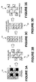
- Figures 4a-4g illustrate another embodiment of a mapping, compression, decompression, and remapping process that can be employed by the method of Figure 2.
- Figure 5 shows an embodiment of an image sensor system that can implement the method and processes of Figures 2-4.
- Embodiments of a method and apparatus for color image data processing and compression are described in detail herein.
- numerous specific details are provided, such as the components of the hardware for color image processing in Figure 5, to provide a thorough understanding of embodiments of the invention.
- One skilled in the relevant art will recognize, however, that the invention can be practiced without one or more of the specific details, or with other methods, components, etc.
- well-known structures or operations are not shown or described in detail to avoid obscuring aspects of various embodiments of the invention.
- FIG. 2 is a flow diagram 30 illustrating an embodiment of the present invention.
- a raw data source that provides image data, such as a RGB raw data source corresponding to a standard Bayer pattern.
- RGB data is described herein for illustrative purposes and for simplicity of explanation, it is understood that the block 12 may provide other color image data formats.
- the block 12 may be a CYM (Cyan, Yellow, Magenta) raw data source, CYWG (Cyan, Yellow, White, Green) raw data source, or any other color-coding schemes.
- the pattern of the RGB raw data from the raw data source of the block 12 is reordered or reorganized by a mapping algorithm.
- This mapping will be described in further detail below with reference to Figure 3, and generally involves reordering non-square color patterns of the RGB raw data into color patterns that are more easily processed by standard compression algorithms.
- the reordered RGB patterns are compressed by a compression engine, using a compression algorithm such as a JPEG-based algorithm, Discrete Cosine Transform (DCT)-based algorithm, or other suitable compression algorithms.
- a compression algorithm such as a JPEG-based algorithm, Discrete Cosine Transform (DCT)-based algorithm, or other suitable compression algorithms.
- Storage and/or transmission at a block 36 can subsequently follow the compression.
- the compressed data is decompressed into a facsimile of (or substantially the same as) the remapped/reordered RGB patterns that were present prior to compression at the block 34.
- the decompressed RGB patterns at the block 38 comprise most, if not all, of the original color information prior to compression.
- the decompressed RGB patterns are remapped or reordered by a reconstruction algorithm.
- the reconstruction algorithm remaps the decompressed RGB patterns to represent the original RGB raw data pattern that was present prior to the block 32.
- the reconstructed RGB raw data can be interpolated to a YC b C r space, for example, at a block 42. In another embodiment, interpolation to a YUV space can be performed at the block 42.
- image enhancement processing can be performed at the block 44.
- This image enhancement processing can include methods to improve sharpness, color saturation, color rendition, etc.
- an embodiment of the invention makes image enhancement at the block 44 easier to perform and results in enhanced image quality, since much more of the original color content is maintained throughout the process represented in Figure 2.
- the operations performed by the blocks 12 and 32-42 are done in the RGB raw data domain. That is, compression and decompression is performed in the RGB raw data domain, and interpolation from one color space to another color space (e.g., from RGB space to YC b C r space) is not performed by an embodiment of the invention until after decompression at the block 38.
- image enhancement is not performed by an embodiment of the invention until after decompression at the block 38.
- This image enhancement at the block 44 can be performed in the YC b C r domain, and results in the minimization of negative impacts on image quality brought about, in the prior art, by the loss of color information that occurs during interpolation from raw color image data into a standard color space.
- Figures 3a-3e show an embodiment of the process performed by the blocks 12 and 32-40 of Figure 2.
- a standard RGB color pattern 50 is shown, although other color patterns, such as a CYM pattern, may be part of the raw data source.
- the pattern 50 can be embodied in a color filter that is arranged according to a Bayer pattern, for example, that filters and provides light according to the pattem arrangement.
- the pattern 50 comprises a checkerboard pattern having a plurality of red R, blue B, and green G elements.
- the red R and blue B elements/planes are arranged in a square pattern, as shown in Figure 3a.
- the green G elements/planes are usually arranged in a non-square pattern 52. Because most compression algorithms, such as those used by JPEG formats, typically perform the compression process on square patterns in the YC b C r color space, an embodiment of the invention reorders or maps the non-square G-plane pattern 52 into a square G-plane pattern 54 of Figure 3c.
- the green G elements in the non-square pattern 52 are designated G 00 -G 31 , then the elements G 01 , G 10 , G 21 , and G 30 are reordered such that the square G-plane configuration of Figure 3c is obtained. This can occur in the block 32 of Figure 2, for example.
- the data in the square G-plane pattern 54 can be compressed and decompressed, via the blocks 32-38 of Figure 2, to obtain the square pattern 56 of Figure 3d.
- the pattern 56 comprises most, if not all, of the data in the square G-plane pattern 54 of Figure 3c, and is designated as g 00 -g 31 elements in Figure 3d.
- Figure 3e shows a non-square pattern 58 that is a reconstructed version of the pattern 56 of Figure 3d, where the g 01 , g 10 , g 21 , and g 30 elements (representing the original G 01 , G 10 , G 21 , and G 30 elements) are remapped or restored to their original locations.
- the block 40 of Figure 2 can perform this reconstruction after decompression.
- G-plane data is usually compressed into the Y luminance channel of a YC b C r space, while R- and B-plane data is compressed into the C r and C b chrominance channels, respectively. If raw RGB data is applied directly to the compression algorithm without interpolation, a large amount of image degradation in the form of compression artifacts often occurs upon decompression.
- another mapping technique of an embodiment of the invention focuses on mapping or reordering the non-square G-plane data, prior to application of a compression algorithm, into multiple square G-planes.
- the green G elements in the RGB color pattern 50 are identified by G 00 -G 31 designations.
- the green G elements/pixels G 00 , G 01 , G 20 , and G 21 of the pattern 60 of Figure 4b, having even-numbered positions in the horizontal and vertical axes, and the green G elements/pixels G 10 , G 11 , G 30 , and G 31 having odd-numbered positions in the horizontal and vertical axes are mapped to separate square G-planes.
- the green G elements/pixels G 00 , G 01 , G 20 , and G 21 are mapped to a square G-plane pattern 62 of Figure 4c, and the green G elements/pixels G 10 , G 11 , G 30 , and G 31 are mapped to a square G-plane pattern 64 of Figure 4d.
- This mapping into two separate square G-planes (labeled G-plane #0 and G-plane #1) can be performed in the block 32 of Figure 2.
- Figure 5 illustrates an image sensor system 80 that can implement the methods and processes shown in the previous figures and described above.
- color interpolation, image enhancement, and data compression of prior art methods are typically accomplished with specialized hardware.
- decompression is typically accomplished with a host computer and/or software.
- the embodiment of the image sensor system 80 of Figure 5 includes hardware to perform data mapping that is much simpler than the prior art hardware required for color interpolation and image enhancement. This results in hardware of reduced complexity and size. Furthermore; because an embodiment of the invention reserves color interpolation to a standard color space until data is present in the host system ( e.g. , after decompression at the block 38 of Figure 2), color interpolation can be performed using the host computer and software. Similarly, image enhancement at the block 44 can be performed using the host computer and software. The overall result is a savings in the amount of specialized hardware required while improving the quality of the resulting image.
- the image sensor system 80 comprises an image sensor array 82.
- the image sensor array 82 includes a plurality of light-sensing elements, along with one or more color filters arranged in a pattern, such as the RGB color pattern 50 of Figures 3a and 4a. Line signals from the image sensor array 82, corresponding to the different colors in the RGB color pattern 50, are provided to the sensor reading structure 84.
- the sensor reading structure is, in turn, coupled via one or more lines to a reorder/remap unit 86, such that the reorder/remap unit receives a plurality of input signals corresponding to R-, G-, and B-plane color image data (e.g. , the RGB raw data).
- the reorder/remap unit 86 performs the reordering or remapping of the G-plane elements, for example, in a manner such as that shown in Figures 3c, 4c, and 4d.
- the reordered color image data is subsequently provided to a compression unit 88 that can utilize a suitable known compression algorithm and associated hardware to compress the reordered color image data.
- the reorder/remap unit 86 and the compression unit 88 can comprise one or more digital signal processor (DSP) units.
- DSP digital signal processor
- the image sensor array 82, sensor reading structure 84, reorder/remap unit 86, and compression unit 88 are located on a single integrated circuit (IC) chip 90.
- IC integrated circuit
- one or more of these components are not located on-board the IC chip 90, and instead can be located on other IC chips or as separate components in the image sensor system 80. Therefore, embodiments of the invention are not limited by the specific location of the components in the image sensor system 80.
- the color image data compressed by the compression unit 88 can be stored in a storage and/or transmission unit 92.
- the storage and/or transmission unit 92 can comprise any type of suitable machine-readable storage media, including but not limited to, random access memory (RAM), floppy disk, hard disk, etc., and corresponding processing, communication, and transmission hardware that allows stored data to be retrieved and transmitted to other components in the image sensor system 80.
- RAM random access memory
- floppy disk floppy disk
- hard disk etc.
- processing, communication, and transmission hardware that allows stored data to be retrieved and transmitted to other components in the image sensor system 80.
- a host computer 94 (or software) can subsequently process the data stored in the storage and/or transmission unit 92.
- the host computer 94 comprises various hardware (including a processor) and software components, of which only a few are illustrated in Figure 5.
- the host computer 94 is separate from the IC chip 90, while in another embodiment, one or more components of the host computer 94 may be on-board components in the IC chip 90.
- a separate machine-readable medium can have a set of instructions, which when executed by one or more processors (not shown) effectuate the various processes and algorithms described above. Therefore, embodiments of the invention are not limited by the specific location (or location of execution) of the hardware or software components of the host computer 94.
- the host computer 94 includes a decompression unit 96 and a reconstruction unit 98, both of which can be embodied in software, to perform the decompression and reconstruction processes previously described above.
- a color matrix and interpolation unit 100 performs the interpolation, using known techniques.
- the resulting Y luminance data can be received by a luminance signal processing unit 102, and the resulting C b and C r data can be received by a chrominance signal processing unit 104.
- the processing units 102 and 104 can then generate an output signal 106, or they can provide inputs to an image enhancement unit 108, which can intern perform image quality improvement operations on the color image data.
- embodiments of the present invention provide improved color image data by performing a reordering prior to compression, compressing and decompressing the color image data, and then reconstructing the color image data to its original color pattern.
- Interpolation and/or image enhancement can be performed after the color image data is decompressed and reconstructed. The result is that much of the original color image data is preserved throughout the process.
Abstract
Description
- The present invention relates generally to imaging methods and devices, and in particular relates to a method and apparatus for processing and compressing color images by color image sensor devices.
- Current methods of color image or video compression, such as those employed with Joint Photographic Experts Group (JPEG) format, usually process data in a fully interpolated color space. Examples of these color spaces include the YUV space having a 4:2:2 ratio (where Y is a luminance component, and U and V are chrominance components or color difference components) and YCbCr space (where Y is a luminance component, Cb is a chrominance-blue component, and C, is a chrominance-red component). Data is processed in these spaces because a standard raw data stream, such as data in a Bayer pattern, is much more difficult to compress. Also, it is much more difficult to realize high levels of data compression unless done in a standard color space like YCbCr. Thus, most compression algorithms use a preprocessing step of interpolating RGB (Red, Green, Blue) raw data into a standard color space, like YCbCr, prior to applying an image data compression procedure.
- Figure 1 shows a flow diagram 10 illustrating this procedure. RGB raw data at a
block 12 is preprocessed at aninterpolation block 14 that interpolates the RGB raw data into a YCbCr space. Hence, there is a mapping from the RGB raw data domain to the YCbCr domain. From theinterpolation block 14 and while in the YCbCr domain, image enhancement is performed at ablock 16, compression is performed by a compression engine at ablock 18, and storage and/or transmission is performed at ablock 20. At ablock 22, a decompression engine decompresses the color image data. Software is typically used to perform the decompression at theblock 22, while additional specialized hardware is usually used to perform the preprocessing interpolation at theblock 14. - YCbCr data typically comprises eight bits or more of luminance data, and eight bits or more of color data per pixel (e.g., the picture element). Raw RGB data usually comprises eight bits or more of luminance data per pixel, with the pixels arranged in a predetermined pattern, such as in a Bayer pattern. Image data compression is employed to reduce data storage requirements and/or to reduce the bandwidth or time required for transmission of image data from one location to another.
- As shown by the
block 16 of Figure 1, image enhancement processing algorithms usually preprocess YCbCr data before compression is performed at theblock 18, due to the requirement for compression algorithms to have fully interpolated color data to process. Although image enhancement is used to improve sharpness, color saturation, color rendition, and other image parameters, performing image enhancement on YCbCr data can be difficult. For instance, due to the nature of YCbCr and other color space data, YCbCr image data is often devoid of much of the original color information that existed for each pixel prior to interpolation. This complicates the eventual reconstruction of the original image data and renders the achievement of high levels of image quality difficult, if not impossible, to obtain. - Accordingly, improvements are needed in the processing of color image data.
- A method maps an original color image pattern to a first color image pattern. Color image data of the first color image pattern is compressed and decompressed. The decompressed color image data is remapped into a second color image pattern that is substantially the same as the original color image pattern.
- Non-limiting and non-exhaustive embodiments of the present invention will be described in the following figures, wherein like reference numerals refer to like parts throughout the various views unless otherwise specified.
- Figure 1 is a flow diagram illustrating known color image data processing and compression.
- Figure 2 is a flow diagram illustrating color image data processing and compression method according to an embodiment of the invention.
- Figures 3a-3e illustrate an embodiment of a mapping, compression, decompression, and remapping process that can be employed by the method of Figure 2.
- Figures 4a-4g illustrate another embodiment of a mapping, compression, decompression, and remapping process that can be employed by the method of Figure 2.
- Figure 5 shows an embodiment of an image sensor system that can implement the method and processes of Figures 2-4.
- Embodiments of a method and apparatus for color image data processing and compression are described in detail herein. In the following description, numerous specific details are provided, such as the components of the hardware for color image processing in Figure 5, to provide a thorough understanding of embodiments of the invention. One skilled in the relevant art will recognize, however, that the invention can be practiced without one or more of the specific details, or with other methods, components, etc. In other instances, well-known structures or operations are not shown or described in detail to avoid obscuring aspects of various embodiments of the invention.
- Reference throughout this specification to "one embodiment" or "an embodiment" means that a particular feature, structure, or characteristic described in connection with the embodiment is included in at least one embodiment of -the present invention. Thus, the appearances of the phrases "in one embodiment" or "in an embodiment" in various places throughout this specification are not necessarily all referring to the same embodiment. Furthermore, the particular features, structures, or characteristics may be combined in any suitable manner in one or more embodiments.
- Figure 2 is a flow diagram 30 illustrating an embodiment of the present invention. Shown initially at the
block 12 is a raw data source that provides image data, such as a RGB raw data source corresponding to a standard Bayer pattern. Although RGB data is described herein for illustrative purposes and for simplicity of explanation, it is understood that theblock 12 may provide other color image data formats. For instance, theblock 12 may be a CYM (Cyan, Yellow, Magenta) raw data source, CYWG (Cyan, Yellow, White, Green) raw data source, or any other color-coding schemes. - Next at a
block 32, the pattern of the RGB raw data from the raw data source of theblock 12 is reordered or reorganized by a mapping algorithm. This mapping will be described in further detail below with reference to Figure 3, and generally involves reordering non-square color patterns of the RGB raw data into color patterns that are more easily processed by standard compression algorithms. - At a
block 34, the reordered RGB patterns are compressed by a compression engine, using a compression algorithm such as a JPEG-based algorithm, Discrete Cosine Transform (DCT)-based algorithm, or other suitable compression algorithms. Storage and/or transmission at ablock 36 can subsequently follow the compression. Next at ablock 38, the compressed data is decompressed into a facsimile of (or substantially the same as) the remapped/reordered RGB patterns that were present prior to compression at theblock 34. The decompressed RGB patterns at theblock 38 comprise most, if not all, of the original color information prior to compression. - At a
block 40, the decompressed RGB patterns are remapped or reordered by a reconstruction algorithm. The reconstruction algorithm remaps the decompressed RGB patterns to represent the original RGB raw data pattern that was present prior to theblock 32. Subsequently, the reconstructed RGB raw data can be interpolated to a YCbCr space, for example, at ablock 42. In another embodiment, interpolation to a YUV space can be performed at theblock 42. - In addition (or as an alternative) to the interpolation at the
block 42, image enhancement processing can be performed at theblock 44. This image enhancement processing can include methods to improve sharpness, color saturation, color rendition, etc. Unlike the prior art methods previously described above, an embodiment of the invention makes image enhancement at theblock 44 easier to perform and results in enhanced image quality, since much more of the original color content is maintained throughout the process represented in Figure 2. - As shown by the flow diagram 30 of Figure 2, the operations performed by the
blocks 12 and 32-42 are done in the RGB raw data domain. That is, compression and decompression is performed in the RGB raw data domain, and interpolation from one color space to another color space (e.g., from RGB space to YCbCr space) is not performed by an embodiment of the invention until after decompression at theblock 38. - Similarly, image enhancement is not performed by an embodiment of the invention until after decompression at the
block 38. This image enhancement at theblock 44 can be performed in the YCbCr domain, and results in the minimization of negative impacts on image quality brought about, in the prior art, by the loss of color information that occurs during interpolation from raw color image data into a standard color space. - Figures 3a-3e show an embodiment of the process performed by the
blocks 12 and 32-40 of Figure 2. Beginning at Figure 3a, a standardRGB color pattern 50 is shown, although other color patterns, such as a CYM pattern, may be part of the raw data source. Thepattern 50 can be embodied in a color filter that is arranged according to a Bayer pattern, for example, that filters and provides light according to the pattem arrangement. Thepattern 50 comprises a checkerboard pattern having a plurality of red R, blue B, and green G elements. - Typically, the red R and blue B elements/planes are arranged in a square pattern, as shown in Figure 3a. As shown in Figure 3b, the green G elements/planes are usually arranged in a
non-square pattern 52. Because most compression algorithms, such as those used by JPEG formats, typically perform the compression process on square patterns in the YCbCr color space, an embodiment of the invention reorders or maps the non-square G-plane pattern 52 into a square G-plane pattern 54 of Figure 3c. That is, if the green G elements in thenon-square pattern 52 are designated G00-G31, then the elements G01, G10, G21, and G30 are reordered such that the square G-plane configuration of Figure 3c is obtained. This can occur in theblock 32 of Figure 2, for example. - Next, the data in the square G-
plane pattern 54 can be compressed and decompressed, via the blocks 32-38 of Figure 2, to obtain thesquare pattern 56 of Figure 3d. Thepattern 56 comprises most, if not all, of the data in the square G-plane pattern 54 of Figure 3c, and is designated as g00-g31 elements in Figure 3d. Figure 3e shows anon-square pattern 58 that is a reconstructed version of thepattern 56 of Figure 3d, where the g01, g10, g21, and g30 elements (representing the original G01, G10, G21, and G30 elements) are remapped or restored to their original locations. Theblock 40 of Figure 2 can perform this reconstruction after decompression. - With traditional compression algorithms, G-plane data is usually compressed into the Y luminance channel of a YCbCr space, while R- and B-plane data is compressed into the Cr and Cb chrominance channels, respectively. If raw RGB data is applied directly to the compression algorithm without interpolation, a large amount of image degradation in the form of compression artifacts often occurs upon decompression.
- Accordingly, another mapping technique of an embodiment of the invention focuses on mapping or reordering the non-square G-plane data, prior to application of a compression algorithm, into multiple square G-planes. Specifically with reference first to Figure 4a, the green G elements in the
RGB color pattern 50 are identified by G00-G31 designations. The green G elements/pixels G00, G01, G20, and G21 of thepattern 60 of Figure 4b, having even-numbered positions in the horizontal and vertical axes, and the green G elements/pixels G10, G11, G30, and G31 having odd-numbered positions in the horizontal and vertical axes are mapped to separate square G-planes. That is, the green G elements/pixels G00, G01, G20, and G21 are mapped to a square G-plane pattern 62 of Figure 4c, and the green G elements/pixels G10, G11, G30, and G31 are mapped to a square G-plane pattern 64 of Figure 4d. This mapping into two separate square G-planes (labeled G-plane # 0 and G-plane #1) can be performed in theblock 32 of Figure 2. - These even and odd G-planes are then compressed and decompressed as separate planes by the blocks 32-38, as represented by patterns 66-68 having g00-g31 element designations in Figures 4e-4f. After decompression, the two square G-
planes # 0 and #1 are repositioned or remapped by theblock 40 to recreate substantially the original single non-square G-plane pattern 70 shown in Figure 4g. Because the two separate square G-planes, along with the square R and B planes, are applied to the compression algorithm separately, image degradation is dramatically reduced while much more of the original color content is preserved. - Figure 5 illustrates an
image sensor system 80 that can implement the methods and processes shown in the previous figures and described above. As an initial consideration, color interpolation, image enhancement, and data compression of prior art methods, such as that illustrated in Figure 1, are typically accomplished with specialized hardware. As Figure 1 further illustrates, decompression is typically accomplished with a host computer and/or software. - In contrast, the embodiment of the
image sensor system 80 of Figure 5 includes hardware to perform data mapping that is much simpler than the prior art hardware required for color interpolation and image enhancement. This results in hardware of reduced complexity and size. Furthermore; because an embodiment of the invention reserves color interpolation to a standard color space until data is present in the host system (e.g., after decompression at theblock 38 of Figure 2), color interpolation can be performed using the host computer and software. Similarly, image enhancement at theblock 44 can be performed using the host computer and software. The overall result is a savings in the amount of specialized hardware required while improving the quality of the resulting image. - The
image sensor system 80 comprises an image sensor array 82. The image sensor array 82 includes a plurality of light-sensing elements, along with one or more color filters arranged in a pattern, such as theRGB color pattern 50 of Figures 3a and 4a. Line signals from the image sensor array 82, corresponding to the different colors in theRGB color pattern 50, are provided to the sensor reading structure 84. - The sensor reading structure is, in turn, coupled via one or more lines to a reorder/
remap unit 86, such that the reorder/remap unit receives a plurality of input signals corresponding to R-, G-, and B-plane color image data (e.g., the RGB raw data). The reorder/remap unit 86 performs the reordering or remapping of the G-plane elements, for example, in a manner such as that shown in Figures 3c, 4c, and 4d. The reordered color image data is subsequently provided to acompression unit 88 that can utilize a suitable known compression algorithm and associated hardware to compress the reordered color image data. In one embodiment, the reorder/remap unit 86 and thecompression unit 88 can comprise one or more digital signal processor (DSP) units. - According to one embodiment, the image sensor array 82, sensor reading structure 84, reorder/
remap unit 86, andcompression unit 88 are located on a single integrated circuit (IC)chip 90. In another embodiment, one or more of these components are not located on-board theIC chip 90, and instead can be located on other IC chips or as separate components in theimage sensor system 80. Therefore, embodiments of the invention are not limited by the specific location of the components in theimage sensor system 80. - The color image data compressed by the
compression unit 88 can be stored in a storage and/ortransmission unit 92. The storage and/ortransmission unit 92 can comprise any type of suitable machine-readable storage media, including but not limited to, random access memory (RAM), floppy disk, hard disk, etc., and corresponding processing, communication, and transmission hardware that allows stored data to be retrieved and transmitted to other components in theimage sensor system 80. - A host computer 94 (or software) can subsequently process the data stored in the storage and/or
transmission unit 92. Thehost computer 94 comprises various hardware (including a processor) and software components, of which only a few are illustrated in Figure 5. In one embodiment, thehost computer 94 is separate from theIC chip 90, while in another embodiment, one or more components of thehost computer 94 may be on-board components in theIC chip 90. In yet another embodiment, a separate machine-readable medium can have a set of instructions, which when executed by one or more processors (not shown) effectuate the various processes and algorithms described above. Therefore, embodiments of the invention are not limited by the specific location (or location of execution) of the hardware or software components of thehost computer 94. - The
host computer 94 includes adecompression unit 96 and areconstruction unit 98, both of which can be embodied in software, to perform the decompression and reconstruction processes previously described above. If interpolation is to be performed (e.g., from an RGB space to a YCbCr space, for example), a color matrix andinterpolation unit 100 performs the interpolation, using known techniques. The resulting Y luminance data can be received by a luminancesignal processing unit 102, and the resulting Cb and Cr data can be received by a chrominancesignal processing unit 104. Theprocessing units output signal 106, or they can provide inputs to animage enhancement unit 108, which can intern perform image quality improvement operations on the color image data. - In summary, embodiments of the present invention provide improved color image data by performing a reordering prior to compression, compressing and decompressing the color image data, and then reconstructing the color image data to its original color pattern. Interpolation and/or image enhancement can be performed after the color image data is decompressed and reconstructed. The result is that much of the original color image data is preserved throughout the process.
- The above description of illustrated embodiments of the invention is not intended to be exhaustive or to limit the invention to the precise forms disclosed. While specific embodiments of, and examples for, the invention are described herein for illustrative purposes, various equivalent modifications are possible within the scope of the invention, as those skilled in the relevant art will recognize.
- These modifications can be made to the invention in light of the above detailed description. The terms used in the following claims should not be construed to limit the invention to the specific embodiments disclosed in the specification and the claims. Rather, the scope of the invention is to be determined entirely by the following claims, which are to be construed in accordance with established doctrines of claim interpretation.
Claims (18)
- A method, comprising:mapping an original color image pattern to a first color image pattern;compressing and decompressing color image data of the first color image pattern; andremapping the decompressed color image data into a second color image pattern substantially the same as the original color image pattern.
- The method of claim 1, further comprising interpolating color image data of the second color image pattern from a first color space to a second color space.
- The method of claim 1, further comprising performing image enhancement processing on the decompressed color image data of the second color image pattern.
- The method of claim 1, further comprising:interpolating the decompressed color image data of the second color image pattern from an RGB space to a YCbCr color space; andperforming image enhancement processing on the interpolated color image data of the YCbCr color space.
- The method of claim 1 wherein mapping the original color image pattern to the first color image pattern comprises reordering non-square, color plane pattern data of the original color image pattern into square-shaped, color plane pattern data.
- The method of claim 1 wherein mapping the original color image pattern to the first color image pattern comprises reordering a plurality of non-square, color plane pattern data of the original color image pattern into a corresponding plurality of square-shaped, color plane pattern data.
- The method of claim 1 wherein mapping the original color image pattern to the first color image pattern comprises reordering a plurality of non-square, color plane pattern data of the original color image pattern into a corresponding plurality of square-shaped, color plane pattern data, the method further comprising separately compressing and decompressing the plurality of square-shaped, color plane pattern data.
- A method, comprising:receiving color image data arranged in a non-square color image pattern;mapping the non-square color image pattern to a substantially square color image pattern;compressing and decompressing color image data of the substantially square color image pattern; andremapping the decompressed color image data into another color image pattern substantially the same as the non-square color image pattern.
- The method of claim 8, further comprising interpolating color image data of the another color image pattern from an RGB space to a YUV color space.
- The method of claim 8, further comprising performing image enhancement processing on the decompressed color image data of the another color image pattern.
- The method of claim 8, wherein mapping the non-square color image pattern to the substantially square color image pattern comprises reordering a plurality of non-square, color plane pattern data of the non-square color image pattern into a corresponding plurality of square-shaped, color plane pattern data.
- A image sensor system, comprising:an image sensor unit to generate color image data arranged in a first color image pattern;a reorder unit coupled to the image sensor unit to map the first color image pattern into a second color image pattern;a compression/decompression unit coupled the reorder unit to compress and decompress color image data of the second color image pattern received from the reorder unit; anda processor to effect a reconstruction of the decompressed color image data of the second color image pattern into a third color image pattern substantially the same as the first color image pattern.
- The system of claim 12 wherein the processor comprises part of a host computer, the host computer including:a reconstruction unit responsive to the processor to perform the reconstruction of the decompressed color image data; andan interpolation unit to interpolate color image data of the third color image pattern from a first color space to a second color space.
- The system of claim 12, further comprising an image enhancement unit to perform image enhancement on color image data of the third color image pattern.
- The system of claim 12 wherein the image sensor unit and reorder unit are located on a same integrated circuit chip.
- A machine-readable having stored thereon instructions, which if executed by one or more processors, cause the processors to effect the following:map an original color image pattern to a first color image pattern;compress and decompress color image data of the first color image pattern; andremap the decompressed color image data into a second color image pattern substantially the same as the original color image pattern.
- The machine-readable medium of claim 16 wherein the instructions cause the processor to further effect the following:
interpolate color image data of the second color image pattern from a first color space to a second color space. - The machine-readable medium of claim 16 wherein the instructions cause the processor to further effect the following:
perform image enhancement processing on the decompressed color image data of the second color image pattern.
Applications Claiming Priority (2)
| Application Number | Priority Date | Filing Date | Title |
|---|---|---|---|
| US53689200A | 2000-03-28 | 2000-03-28 | |
| US536892 | 2000-03-28 |
Publications (3)
| Publication Number | Publication Date |
|---|---|
| EP1173005A2 true EP1173005A2 (en) | 2002-01-16 |
| EP1173005A3 EP1173005A3 (en) | 2004-05-06 |
| EP1173005B1 EP1173005B1 (en) | 2008-04-09 |
Family
ID=24140351
Family Applications (1)
| Application Number | Title | Priority Date | Filing Date |
|---|---|---|---|
| EP00311101A Expired - Lifetime EP1173005B1 (en) | 2000-03-28 | 2000-12-13 | Method and apparatus for color image data processing and compression |
Country Status (6)
| Country | Link |
|---|---|
| US (1) | US20050084150A1 (en) |
| EP (1) | EP1173005B1 (en) |
| CN (1) | CN1210943C (en) |
| AT (1) | ATE392091T1 (en) |
| DE (1) | DE60038550T2 (en) |
| TW (1) | TW508940B (en) |
Cited By (3)
| Publication number | Priority date | Publication date | Assignee | Title |
|---|---|---|---|---|
| WO2005116927A1 (en) * | 2004-05-31 | 2005-12-08 | Phase One A/S | Image compression for rapid high-quality imaging |
| US7656561B2 (en) | 2004-05-31 | 2010-02-02 | Phase One A/S | Image compression for rapid high-quality imaging |
| EP2508001A4 (en) * | 2009-12-04 | 2016-07-20 | Thomson Licensing | Texture-pattern-adaptive partitioned block transform |
Families Citing this family (16)
| Publication number | Priority date | Publication date | Assignee | Title |
|---|---|---|---|---|
| US7006699B2 (en) * | 2002-03-27 | 2006-02-28 | Microsoft Corporation | System and method for progressively transforming and coding digital data |
| JP4451181B2 (en) * | 2004-03-26 | 2010-04-14 | オリンパス株式会社 | Image compression method and image compression apparatus |
| US7755817B2 (en) * | 2004-12-07 | 2010-07-13 | Chimei Innolux Corporation | Color gamut mapping |
| CN100425080C (en) * | 2005-05-25 | 2008-10-08 | 凌阳科技股份有限公司 | Edge strengthening method and device of Bel image and color image pick-up system |
| US7936835B1 (en) | 2006-07-14 | 2011-05-03 | Pmc-Sierra, Inc. | Adaptive signal decompression |
| DE102006043068B4 (en) * | 2006-09-14 | 2009-01-29 | Olympus Soft Imaging Solutions Gmbh | Method for transmitting color data obtained with the aid of a recording device |
| US8565519B2 (en) | 2007-02-09 | 2013-10-22 | Qualcomm Incorporated | Programmable pattern-based unpacking and packing of data channel information |
| US8165394B2 (en) * | 2008-09-18 | 2012-04-24 | Microsoft Corporation | Reconstruction of image in a Bayer pattern |
| US20110311144A1 (en) * | 2010-06-17 | 2011-12-22 | Microsoft Corporation | Rgb/depth camera for improving speech recognition |
| JP2014093568A (en) * | 2012-10-31 | 2014-05-19 | Canon Inc | Moving image encoder, imaging apparatus, and control method for moving image encoder |
| CN106339657B (en) * | 2015-07-09 | 2019-02-22 | 张�杰 | Crop straw burning monitoring method based on monitor video, device |
| CN106228581B (en) * | 2016-08-01 | 2019-06-21 | 武汉斗鱼网络科技有限公司 | Pixel format is converted to the method and system of NV12 by GPU by ARGB |
| CN109348202B (en) * | 2018-08-01 | 2021-01-08 | 深圳朗田亩半导体科技有限公司 | Image saturation adjusting method and device |
| TWI686772B (en) * | 2019-03-21 | 2020-03-01 | 國立清華大學 | Data restoring method using compressed sensing and computer program product |
| KR102436812B1 (en) * | 2020-11-27 | 2022-08-26 | 주식회사 넥스트칩 | Method and apparaus for exchanging protocol information |
| KR102409700B1 (en) * | 2021-03-15 | 2022-06-15 | 아주대학교산학협력단 | Apparatus and method for processing image |
Citations (3)
| Publication number | Priority date | Publication date | Assignee | Title |
|---|---|---|---|---|
| EP0508607A2 (en) * | 1991-03-13 | 1992-10-14 | Canon Kabushiki Kaisha | Electronic still camera |
| US5734779A (en) * | 1990-11-05 | 1998-03-31 | Canon Kabushiki Kaisha | Image pickup device having a plurality of pickup element regions and a color filter |
| EP0907294A1 (en) * | 1997-03-21 | 1999-04-07 | Mitsubishi Denki Kabushiki Kaisha | Image processing device and still image pickup device, and method for processing image |
Family Cites Families (2)
| Publication number | Priority date | Publication date | Assignee | Title |
|---|---|---|---|---|
| KR960036647A (en) * | 1995-03-20 | 1996-10-28 | 배순훈 | Bit Plan Compression Transmission Device Using Scanning |
| KR100200628B1 (en) * | 1996-09-30 | 1999-06-15 | 윤종용 | Image quality enhancement circuit and method thereof |
-
2000
- 2000-12-08 TW TW089126308A patent/TW508940B/en not_active IP Right Cessation
- 2000-12-13 EP EP00311101A patent/EP1173005B1/en not_active Expired - Lifetime
- 2000-12-13 DE DE60038550T patent/DE60038550T2/en not_active Expired - Lifetime
- 2000-12-13 AT AT00311101T patent/ATE392091T1/en not_active IP Right Cessation
-
2001
- 2001-02-28 CN CNB011109122A patent/CN1210943C/en not_active Expired - Lifetime
-
2004
- 2004-11-10 US US10/985,554 patent/US20050084150A1/en not_active Abandoned
Patent Citations (3)
| Publication number | Priority date | Publication date | Assignee | Title |
|---|---|---|---|---|
| US5734779A (en) * | 1990-11-05 | 1998-03-31 | Canon Kabushiki Kaisha | Image pickup device having a plurality of pickup element regions and a color filter |
| EP0508607A2 (en) * | 1991-03-13 | 1992-10-14 | Canon Kabushiki Kaisha | Electronic still camera |
| EP0907294A1 (en) * | 1997-03-21 | 1999-04-07 | Mitsubishi Denki Kabushiki Kaisha | Image processing device and still image pickup device, and method for processing image |
Cited By (3)
| Publication number | Priority date | Publication date | Assignee | Title |
|---|---|---|---|---|
| WO2005116927A1 (en) * | 2004-05-31 | 2005-12-08 | Phase One A/S | Image compression for rapid high-quality imaging |
| US7656561B2 (en) | 2004-05-31 | 2010-02-02 | Phase One A/S | Image compression for rapid high-quality imaging |
| EP2508001A4 (en) * | 2009-12-04 | 2016-07-20 | Thomson Licensing | Texture-pattern-adaptive partitioned block transform |
Also Published As
| Publication number | Publication date |
|---|---|
| CN1315804A (en) | 2001-10-03 |
| US20050084150A1 (en) | 2005-04-21 |
| CN1210943C (en) | 2005-07-13 |
| EP1173005A3 (en) | 2004-05-06 |
| ATE392091T1 (en) | 2008-04-15 |
| TW508940B (en) | 2002-11-01 |
| DE60038550T2 (en) | 2009-06-18 |
| DE60038550D1 (en) | 2008-05-21 |
| EP1173005B1 (en) | 2008-04-09 |
Similar Documents
| Publication | Publication Date | Title |
|---|---|---|
| EP1173005A2 (en) | Method and apparatus for color image data processing and compression | |
| US20200195851A1 (en) | Compression and decoding of single sensor color image data | |
| EP0235456B1 (en) | Image processing apparatus and method with blocks of compressed data | |
| US6825876B1 (en) | Digital camera device with methodology for efficient color conversion | |
| US6819801B2 (en) | System and method for processing demosaiced images to reduce color aliasing artifacts | |
| EP0651562A1 (en) | An electronic camera utilizing image compression feedback for improved color processing | |
| US20050213830A1 (en) | Image processing device and method | |
| Malvar et al. | Progressive-to-lossless compression of color-filter-array images using macropixel spectral-spatial transformation | |
| US6563946B2 (en) | Image processing apparatus and method | |
| JP4683678B2 (en) | Image signal processing method, image signal processing system, storage medium, and imaging apparatus | |
| US7194129B1 (en) | Method and system for color space conversion of patterned color images | |
| EP0781493B1 (en) | Packed yuv9 format for interleaved storage and efficient processing of digital video data | |
| US6684000B1 (en) | Image sensing device capable of outputting image signals by blocks and processing circuit which processes image signals by blocks | |
| US7158178B1 (en) | Method of converting a sub-sampled color image | |
| US7146055B2 (en) | Image processing decompression apparatus and method of using same different scaling algorithms simultaneously | |
| WO2020007990A1 (en) | Compression of a raw image | |
| US20090202165A1 (en) | Image decoding method and image decoding apparatus | |
| US20040252894A1 (en) | Image compression apparatus and image processing system | |
| JP2809552B2 (en) | Image encoding method and image decoding method | |
| US20170223358A1 (en) | Method and device for encoding a multidimensional digital signal, in particular an image signal, and corresponding method and device for decoding | |
| WO2001054397A2 (en) | Improved digital camera device with methodology for efficient color conversion | |
| JP2810585B2 (en) | Image encoding method and image decoding method | |
| JP2002271794A (en) | Image processing unit performing sampling of compressed image | |
| JP2004158948A (en) | Image data processing method | |
| JPH1075463A (en) | Image compressor and image expander |
Legal Events
| Date | Code | Title | Description |
|---|---|---|---|
| PUAI | Public reference made under article 153(3) epc to a published international application that has entered the european phase |
Free format text: ORIGINAL CODE: 0009012 |
|
| AK | Designated contracting states |
Kind code of ref document: A2 Designated state(s): AT BE CH CY DE DK ES FI FR GB GR IE IT LI LU MC NL PT SE TR |
|
| AX | Request for extension of the european patent |
Free format text: AL;LT;LV;MK;RO;SI |
|
| PUAL | Search report despatched |
Free format text: ORIGINAL CODE: 0009013 |
|
| AK | Designated contracting states |
Kind code of ref document: A3 Designated state(s): AT BE CH CY DE DK ES FI FR GB GR IE IT LI LU MC NL PT SE TR |
|
| AX | Request for extension of the european patent |
Extension state: AL LT LV MK RO SI |
|
| 17P | Request for examination filed |
Effective date: 20040609 |
|
| AKX | Designation fees paid |
Designated state(s): AT BE CH CY DE DK ES FI FR GB GR IE IT LI LU MC NL PT SE TR |
|
| GRAP | Despatch of communication of intention to grant a patent |
Free format text: ORIGINAL CODE: EPIDOSNIGR1 |
|
| GRAS | Grant fee paid |
Free format text: ORIGINAL CODE: EPIDOSNIGR3 |
|
| GRAA | (expected) grant |
Free format text: ORIGINAL CODE: 0009210 |
|
| AK | Designated contracting states |
Kind code of ref document: B1 Designated state(s): AT BE CH CY DE DK ES FI FR GB GR IE IT LI LU MC NL PT SE TR |
|
| REG | Reference to a national code |
Ref country code: GB Ref legal event code: FG4D |
|
| REG | Reference to a national code |
Ref country code: CH Ref legal event code: EP |
|
| REG | Reference to a national code |
Ref country code: IE Ref legal event code: FG4D |
|
| REF | Corresponds to: |
Ref document number: 60038550 Country of ref document: DE Date of ref document: 20080521 Kind code of ref document: P |
|
| NLV1 | Nl: lapsed or annulled due to failure to fulfill the requirements of art. 29p and 29m of the patents act | ||
| PG25 | Lapsed in a contracting state [announced via postgrant information from national office to epo] |
Ref country code: ES Free format text: LAPSE BECAUSE OF FAILURE TO SUBMIT A TRANSLATION OF THE DESCRIPTION OR TO PAY THE FEE WITHIN THE PRESCRIBED TIME-LIMIT Effective date: 20080720 Ref country code: NL Free format text: LAPSE BECAUSE OF FAILURE TO SUBMIT A TRANSLATION OF THE DESCRIPTION OR TO PAY THE FEE WITHIN THE PRESCRIBED TIME-LIMIT Effective date: 20080409 Ref country code: PT Free format text: LAPSE BECAUSE OF FAILURE TO SUBMIT A TRANSLATION OF THE DESCRIPTION OR TO PAY THE FEE WITHIN THE PRESCRIBED TIME-LIMIT Effective date: 20080909 Ref country code: FI Free format text: LAPSE BECAUSE OF FAILURE TO SUBMIT A TRANSLATION OF THE DESCRIPTION OR TO PAY THE FEE WITHIN THE PRESCRIBED TIME-LIMIT Effective date: 20080409 |
|
| PG25 | Lapsed in a contracting state [announced via postgrant information from national office to epo] |
Ref country code: AT Free format text: LAPSE BECAUSE OF FAILURE TO SUBMIT A TRANSLATION OF THE DESCRIPTION OR TO PAY THE FEE WITHIN THE PRESCRIBED TIME-LIMIT Effective date: 20080409 |
|
| ET | Fr: translation filed | ||
| PG25 | Lapsed in a contracting state [announced via postgrant information from national office to epo] |
Ref country code: SE Free format text: LAPSE BECAUSE OF FAILURE TO SUBMIT A TRANSLATION OF THE DESCRIPTION OR TO PAY THE FEE WITHIN THE PRESCRIBED TIME-LIMIT Effective date: 20080709 Ref country code: DK Free format text: LAPSE BECAUSE OF FAILURE TO SUBMIT A TRANSLATION OF THE DESCRIPTION OR TO PAY THE FEE WITHIN THE PRESCRIBED TIME-LIMIT Effective date: 20080409 |
|
| PLBE | No opposition filed within time limit |
Free format text: ORIGINAL CODE: 0009261 |
|
| STAA | Information on the status of an ep patent application or granted ep patent |
Free format text: STATUS: NO OPPOSITION FILED WITHIN TIME LIMIT |
|
| PG25 | Lapsed in a contracting state [announced via postgrant information from national office to epo] |
Ref country code: BE Free format text: LAPSE BECAUSE OF FAILURE TO SUBMIT A TRANSLATION OF THE DESCRIPTION OR TO PAY THE FEE WITHIN THE PRESCRIBED TIME-LIMIT Effective date: 20080409 |
|
| 26N | No opposition filed |
Effective date: 20090112 |
|
| PG25 | Lapsed in a contracting state [announced via postgrant information from national office to epo] |
Ref country code: MC Free format text: LAPSE BECAUSE OF NON-PAYMENT OF DUE FEES Effective date: 20081231 |
|
| REG | Reference to a national code |
Ref country code: CH Ref legal event code: PL |
|
| PG25 | Lapsed in a contracting state [announced via postgrant information from national office to epo] |
Ref country code: IT Free format text: LAPSE BECAUSE OF FAILURE TO SUBMIT A TRANSLATION OF THE DESCRIPTION OR TO PAY THE FEE WITHIN THE PRESCRIBED TIME-LIMIT Effective date: 20080409 |
|
| PG25 | Lapsed in a contracting state [announced via postgrant information from national office to epo] |
Ref country code: CY Free format text: LAPSE BECAUSE OF FAILURE TO SUBMIT A TRANSLATION OF THE DESCRIPTION OR TO PAY THE FEE WITHIN THE PRESCRIBED TIME-LIMIT Effective date: 20080409 |
|
| PG25 | Lapsed in a contracting state [announced via postgrant information from national office to epo] |
Ref country code: CH Free format text: LAPSE BECAUSE OF NON-PAYMENT OF DUE FEES Effective date: 20081231 Ref country code: IE Free format text: LAPSE BECAUSE OF NON-PAYMENT OF DUE FEES Effective date: 20081215 Ref country code: LI Free format text: LAPSE BECAUSE OF NON-PAYMENT OF DUE FEES Effective date: 20081231 |
|
| PG25 | Lapsed in a contracting state [announced via postgrant information from national office to epo] |
Ref country code: LU Free format text: LAPSE BECAUSE OF NON-PAYMENT OF DUE FEES Effective date: 20081213 |
|
| PG25 | Lapsed in a contracting state [announced via postgrant information from national office to epo] |
Ref country code: TR Free format text: LAPSE BECAUSE OF FAILURE TO SUBMIT A TRANSLATION OF THE DESCRIPTION OR TO PAY THE FEE WITHIN THE PRESCRIBED TIME-LIMIT Effective date: 20080409 |
|
| PG25 | Lapsed in a contracting state [announced via postgrant information from national office to epo] |
Ref country code: GR Free format text: LAPSE BECAUSE OF FAILURE TO SUBMIT A TRANSLATION OF THE DESCRIPTION OR TO PAY THE FEE WITHIN THE PRESCRIBED TIME-LIMIT Effective date: 20080710 |
|
| REG | Reference to a national code |
Ref country code: FR Ref legal event code: PLFP Year of fee payment: 16 |
|
| REG | Reference to a national code |
Ref country code: FR Ref legal event code: PLFP Year of fee payment: 17 |
|
| REG | Reference to a national code |
Ref country code: FR Ref legal event code: PLFP Year of fee payment: 18 |
|
| PGFP | Annual fee paid to national office [announced via postgrant information from national office to epo] |
Ref country code: FR Payment date: 20171120 Year of fee payment: 18 |
|
| PGFP | Annual fee paid to national office [announced via postgrant information from national office to epo] |
Ref country code: GB Payment date: 20171128 Year of fee payment: 18 |
|
| PGFP | Annual fee paid to national office [announced via postgrant information from national office to epo] |
Ref country code: DE Payment date: 20171221 Year of fee payment: 18 |
|
| REG | Reference to a national code |
Ref country code: DE Ref legal event code: R119 Ref document number: 60038550 Country of ref document: DE |
|
| GBPC | Gb: european patent ceased through non-payment of renewal fee |
Effective date: 20181213 |
|
| PG25 | Lapsed in a contracting state [announced via postgrant information from national office to epo] |
Ref country code: DE Free format text: LAPSE BECAUSE OF NON-PAYMENT OF DUE FEES Effective date: 20190702 Ref country code: FR Free format text: LAPSE BECAUSE OF NON-PAYMENT OF DUE FEES Effective date: 20181231 |
|
| PG25 | Lapsed in a contracting state [announced via postgrant information from national office to epo] |
Ref country code: GB Free format text: LAPSE BECAUSE OF NON-PAYMENT OF DUE FEES Effective date: 20181213 |