EP1172978A2 - Diversitätsdetektion von PPM-Signalen - Google Patents
Diversitätsdetektion von PPM-Signalen Download PDFInfo
- Publication number
- EP1172978A2 EP1172978A2 EP01111206A EP01111206A EP1172978A2 EP 1172978 A2 EP1172978 A2 EP 1172978A2 EP 01111206 A EP01111206 A EP 01111206A EP 01111206 A EP01111206 A EP 01111206A EP 1172978 A2 EP1172978 A2 EP 1172978A2
- Authority
- EP
- European Patent Office
- Prior art keywords
- component
- signal
- pcs
- dcs
- symbol
- Prior art date
- Legal status (The legal status is an assumption and is not a legal conclusion. Google has not performed a legal analysis and makes no representation as to the accuracy of the status listed.)
- Granted
Links
Images


Classifications
-
- H—ELECTRICITY
- H04—ELECTRIC COMMUNICATION TECHNIQUE
- H04L—TRANSMISSION OF DIGITAL INFORMATION, e.g. TELEGRAPHIC COMMUNICATION
- H04L25/00—Baseband systems
- H04L25/38—Synchronous or start-stop systems, e.g. for Baudot code
- H04L25/40—Transmitting circuits; Receiving circuits
- H04L25/49—Transmitting circuits; Receiving circuits using code conversion at the transmitter; using predistortion; using insertion of idle bits for obtaining a desired frequency spectrum; using three or more amplitude levels ; Baseband coding techniques specific to data transmission systems
- H04L25/4902—Pulse width modulation; Pulse position modulation
Definitions
- the present invention is related to an apparatus and a method for determining a pulse position for a signal encoded by a pulse modulation.
- a data signal via a channel or media, e.g. via a wire, a fiber, radio frequency (RF), or infrared.
- RF radio frequency
- the present invention is applicable in a broad variety of signal processing applications and is independent from the transmission channel it will be described with the focus put on an application to wireless optical communication.
- infrared links have been classified according to whether they employ a directional or non-directional transmitter and receiver, and whether or not they rely upon the existence of an uninterrupted line-of-sight path between the receiver and the transmitter.
- directed line-of-sight links hereinafter abbreviated to LOS.
- LOS directed line-of-sight links
- a unit which is able to transmit and receive infrared signals is called a transceiver or transceiver module.
- Practical wireless infrared transceiver modules are often restricted to use one optical receiver, which might be a photodiode (PD) and one optical emitter, which might be a light emitting diode (LED).
- PD photodiode
- LED light emitting diode
- IrDA Infrared Data Association
- IrDA-AIr Advanced Infrared
- the current implementation of the IrDA-AIr standard implies one single transceiver module with increased transmission distance and angular range (emission/reception characteristics) of up to 120 degrees, and a standard controller for handling physical layer functions and medium access control.
- US Patent No. 5,566,022 is related to an infrared communication system.
- the system includes a plurality of infrared transceivers for receiving and transmitting infrared signals through the free air.
- a circuit determines the direction of arrival of the received signal and provides this information to a dedicated logic controller (DLC), for registration purposes and for controlling the respective infrared transmitter.
- DLC dedicated logic controller
- SNR signal-to-noise ratio
- the invention for achieving the objects is defined in the claims.
- the signal has at least two components: a first digital signal and a second digital signal.
- the first digital signal is considered as the signal with the best signal quality whereas the second digital signal is considered as the signal with the second-best signal quality.
- These digital signals consist of symbols which represent data in the form of frames whereby each frame comprises at least a header field containing a preamble and a data field. It can be assumed that each received digital signal comprises the same data, because each signal comes from the same source, i.e. from the same transmitter. In case where the received signals originate from different transmitters it is assumed that all transmitted signals adhere to the same standardized form of frames.
- the use of only two signals is justified by the observation that in systems with line-of-sight operation at most two transceivers will detect significant signal power.
- the received symbols are temporarily stored in registers or storage units.
- the most-likely correct symbol is determined which bases on Bayes' probability rule.
- the most-likely correct symbols are stored in a memory in form of a probability table for readout.
- the probability table can also be implemented with discrete logic circuits that compute the most-likely correct symbols.
- the symbol with the largest a posteriori probability is derived, representing the most-likely symbol that has been really sent, and can be used for further processing where each 4-PPM symbol represents a unique pulse position.
- An effective increase in the signal-to-noise ratio (SNR) of up to at least 3 dB can be realized when the pulse position is derived from at least two digital symbols.
- the probability table is an asymmetric table, preferably a diagonally asymmetric table
- the advantage occurs that the content of the table is suited for realistic conditions where we have a best and second-best digital signal.
- the first digital signal shows a legal symbol, i.e. the first digital signal is not distorted or influenced by noise or the noise modifies the transmitted symbol into another legal symbol
- the second digital signal that might be distorted, has no influence on the result of the determination of the pulse position. If the quality of the first digital signal is better than the quality of the second digital signal, then the asymmetric table is best applicable. When the digital signals are of equal quality, then the asymmetric table is still applicable without much performance loss.
- a combination of two or more probability tables or even the combination of the asymmetric and symmetric table would improve the ability to determine the pulse position under various channel conditions.
- the probability table can be stored in simple memory, such as a read only memory (ROM) and/or a random access memory (RAM).
- simple memory such as a read only memory (ROM) and/or a random access memory (RAM).
- the pulse modulation is a Pulse Position Modulation (PPM), preferably a 4-PPM modulation, then the advantage occurs that the data can be transmitted in the baseband and therefore no complex modulation techniques are necessary.
- PPM Pulse Position Modulation
- a Pulse Position Modulation scheme hereinafter abbreviated to PPM, is used in accordance with the present invention. It should be noted, that other modulations schemes can be used instead, especially advantageous are pulse modulations, e.g. Run-Length Limited codes, also abbreviated to RLL.
- the PPM provides a variable data rate with repetition coding.
- the preamble is a preamble
- a digital signal represents data carried in frames, whereby each frame comprises at least a data field and a header field which contains a preamble.
- the preamble comprises a periodic symbol sequence to allow for initial carrier sensing, symbol clock synchronization, and chip clock phase acquisition by a phase-locked loop, also referred to as PLL.
- PLL phase-locked loop
- the preamble is employed to obtain initial relative synchronization of a digital reception- and processing-unit, which is achieved by the transmission of a periodic sequence of pulses.
- a receiving station which knows how many slots each symbol comprises, is able to detect after a certain while the period of the sequence of pulses. Furthermore, the receiving station adjusts its slot or chip clock phase using a PLL.
- the preamble may follow a synchronization field, a control field, the data field or other fields.
- FIG. 1 shows a schematic illustration of an arrangement with three transceivers, labeled TR1, TR2, TR3, the accompanying output signals, labeled S1, S2, S3, respectively, a channel selector 60 and units for synchronization 6 and single-channel data detection 7.
- Each of the three transceivers delivers a binary-quantized signal to the channel selector 60 that delivers the one digital signal with the best signal quality measure, called the primary channel signal and hereafter abbreviated to PCS, to synchronization unit 6 and single-channel data detector 7.
- the synchronization unit 6 feeds a first control signal, hereafter abbreviated to CTL1, and a first clock signal, hereafter abbreviated to CLK1, to the channel selector 60.
- the synchronization unit 6 further feeds a second control signal, hereafter abbreviated to CTL2, and a second clock signal, hereafter abbreviated to CLK2, to the single-channel data detector 7.
- the latter outputs a received data signal, labeled RD, and a third clock signal, labeled CLK3.
- the single-channel data detector 7 receives as a further input a control signal, labeled RR, that carries information about the data rate reduction factor.
- the synchronization unit 6 and the single-channel data detector 7 are usually parts of a controller module 8 that contains further reception and transmission functions.
- the channel selector 60, the synchronization unit 6, and the single-channel data detector 7 can all be combined within such a controller module 8. Subsequently, the channel selector 60 and the synchronization unit 6 will be described in more detail.
- Figure 1a shows in greater detail that the synchronization unit 6 introduced in Fig. 1 includes a data synchronization detector, labeled DSD, a phase-locked loop, labeled PLL, an oscillator, labeled OSC, and a preamble detector, labeled PD.
- the synchronization unit 6 has the PCS as an input and outputs control signals CTL1 and CTL2 and clock signals CLK1 and CLK2.
- Figure 2 shows in more detail that the channel selector 60, also simply called selector 60, contains for each of the three channels a jitter estimator 2, a minimum detector 62, and a primary multiplexer 64 for the selection of the PCS.
- Each of the three jitter estimators 2 receives one binary input signal, labeled S1, S2, and S3, and outputs a channel quality measure, labeled J1, J2, and J3, respectively.
- These channel quality measures J1, J2, J3 are fed to and evaluated by the minimum detector 62 to generate the selection signals, labeled M1 and M2, that select the PCS at the output of the primary multiplexer 64.
- the three jitter estimators 2 are all driven by the clock signal CLK1 and the minimum detector 62 uses control signal CTL1 and clock signal CLK1. Subsequently, the jitter estimator 2 and the minimum detector 62 will be described in more detail.
- FIG. 3 shows the principal blocks of the jitter estimator 2 with a sampler 10, an edge detector 20, a counter 30, a deviation detector 40, and a leaky integrator 50.
- the sampler 10 uniformly samples a digital signal which is a binary-quantized input signal, labeled S, once for each cycle of the clock signal, labeled CLK, such that, for example, six samples result within the time span of a nominal 4-PPM pulse width of 125 ns.
- the clock signal labeled CLK is also fed to the edge detector 20, the counter 30, the deviation detector 40, and the leaky integrator 50.
- the clock signal labeled CLK is identical with clock signal CLK1, the first clock signal delivered by the synchronization unit 6 shown in Fig. 1a.
- the sampler 10 feeds its output to the edge detector 20 which provides a state change in its output signal, labeled CE, during the one cycle of the clock signal CLK where the edge detector 20 identifies a defined edge in the samples provided by the sampler 10.
- the output signal CE of the edge detector 20 is fed to the counter 30 and the leaky integrator 50. Every state change in the output signal CE of the edge detector 20 that coincides with the identification of a defined edge resets the output of the counter 30, labeled EEC, to the value zero, otherwise the counter 30 increments its output by unity for each completed cycle of the clock signal CLK.
- the deviation detector 40 further processes the instantaneous deviation value RJ in a first step by retaining only its magnitude value
- MAX . Therefore, the output of the deviation detector 40, labeled PJ, is determined as PJ
- MAX or PJ
- the output PJ produced by the deviation detector 40 is identical with the input of the leaky integrator 50 whose output J provides a signal quality measure for the input signal S applied to the sampler 10.
- the output of the leaky integrator 50 is also fed back to the edge detector 20 to control the conditions for the detection of a defined edge. Subsequently, the edge detector 20, the deviation detector 40, and the leaky integrator 50, will be described in more detail.
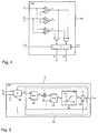
- Figure 4 shows in detail a minimum detector 62 that compares three input values, labeled J1, J2, and J3, by using three comparators, labeled CP1, CP2, and CP3, that assign binary values to their outputs, labeled O1, O2, and O3, respectively. From these output values the selection signals for the primary multiplexer 64, labeled M1 and M2, are then generated by using digital logic circuits and storing the selection signals in storage latches, labeled PL, that are driven by the previously defined clock signal CLK1 and control signal CTL1.
- Figure 5 shows the structure of the jitter estimator 2 with a jitter detector 22, described in further detail in Fig. 6, and a leaky integrator 50 that is constructed with two adders 52,53, a leak factor multiplier 54, a positive value limiter 55, and a clocked storage latch 56.
- the jitter estimator 2 receives a binary-quantized input signal, labeled Sn/S, together with the previously defined clock signal CLK1 that is internally labeled as CLK, and it feeds its output, labeled PJ, to the leaky integrator 50.
- J 0 the value of J i at initialization time ⁇ 0
- J 0 4 according to Fig 5 since the output of the positive value limiter, labeled LNJ, is shown to be limited to four.
- the left-directed arrow ⁇ used in the above update equations indicates a clock-induced output update of the storage latch 56.
- the clock signal labeled CLK becomes active for the storage latch 56 depends on the state of its enabling input, labeled EN, that is identical with the output of the jitter detector 22, labeled CE.
- the output of the leaky integrator 50 labeled J, that provides a signal quality measure for the input signal Sn/S of the jitter estimator 2
- J the output of the leaky integrator 50
- Figure 6 shows a detailed schematics of a jitter detector 22 as introduced in Fig. 5 whose inputs are the binary-quantized signal S, the signal quality measure J, and the clock signal CLK that is identical with the previously defined clock signal CLK1, the first clock signal delivered by the synchronization unit 6 shown in Fig. 1a.
- the outputs of the jitter estimator 22, labeled PJ and CE, are used by the leaky integrator 50 shown in Fig. 5.
- the jitter detector 22 is built with an edge detector 20 that is shown in more detail in Fig. 7, a counter 30, and a deviation detector 40 that includes an adder 44, an absolute value limiter 42, and a storage latch 43.
- the edge detector 20 provides a state change in its output signal, labeled CE, during the one cycle of the clock signal CLK where the edge detector 20 identifies a defined edge in the samples taken from the input signal S; the output signal CE is also fed to the counter 30 and the storage latch 43. Note that the clock signal labeled CLK is also fed to the counter 30 and the storage latch 43 within the deviation detector 40. Every state change in the output signal of the edge detector 20 that coincides with the identification of a defined edge resets the output of the counter 30, labeled EEC, to the value zero, otherwise the counter 30 increments its output by unity for each completed cycle of the clock signal CLK.
- the positive value limiter 42 further processes the instantaneous deviation value RJ in a first step by retaining only its magnitude value
- MAX or LPJ
- the output PJ produced by the deviation detector 40 is identical with the output of the storage latch 43 whose input is provided by the absolute value limiter 42 in the form of its output labeled LPJ.
- the clock signal labeled CLK becomes active for the storage latch 43 depends on the state of its enabling input, labeled EN, that is identical with the output CE of the edge detector 20. Subsequently, the edge detector 20 will be described in more detail.
- Figure 7 shows a circuit diagram of the edge detector 20 which works in two modes, whose output is labeled CE, that includes a comparator, labeled CP, whose output, labeled EDC, controls the conditions for the detection of a defined edge depending on a prestored threshold value, labeled JT.
- the edge detector 20 also includes four storage latches, denoted L1, L2, L3, and L4, used to hold the four most recent samples of the binary-quantized input signal S.
- the first storage latch, labeled L1 also serves as a sampler 10.
- Further inputs are the signal quality measure J and the clock signal CLK that drives the storage latches and is identical with the previously defined clock signal CLK1, the first clock signal delivered by the synchronization unit 6 shown in Fig.
- Figure 8 shows a schematic illustration of an arrangement with three transceivers, labeled TR1, TR2, TR3, and the accompanying output signals, labeled S1, S2, S3, respectively, which feed a receiver system 80 that includes a channel multiplexer 70, here also simply called selector 70, a unit for synchronization 6, and a dual-channel data detector 100.
- TR1, TR2, TR3 the accompanying output signals
- S1, S2, S3 the accompanying output signals
- Each of the three transceivers delivers a binary-quantized signal to the channel multiplexer 70 that delivers a first digital signal, called the first component or primary channel signal, hereafter abbreviated by PCS and characterized as the received signal with the best signal quality measure, and a second digital signal, called the second component or the diversity channel signal, hereafter abbreviated by DCS and characterized as the received signal with the second-best signal quality measure, for further processing by the dual-channel data detector 100.
- PCS first digital signal
- DCS second digital signal
- a dual-channel data detector 100 generally achieves an improved error-rate performance.
- the PCS is also connected to the synchronization unit 6 which can be identical with the synchronization unit 6 that was already introduced and described in accordance with Fig. 1a.
- the synchronization unit 6 feeds a first control signal, hereafter abbreviated to CTL1, and a first clock signal, hereafter abbreviated to CLK1, to the channel multiplexer 70.
- the synchronization unit 6 further feeds a second control signal, hereafter abbreviated to CTL2, and a second clock signal, hereafter abbreviated to CLK2, to the dual-channel data detector 100; the latter receives also a further control signal from the channel multiplexer 70, labeled ECF.
- the dual-channel data detector 100 outputs a received data signal, labeled RD, and a fourth clock signal, labeled CLK4.
- the dual-channel data detector 100 receives as a further input a control signal carrying information about the data rate reduction factor, labeled RR.
- the synchronization unit 6 and the dual-channel data detector 100 can be parts of some controller module that contains further reception and transmission functions. In a further embodiment of the scheme disclosed in Fig. 8, the channel multiplexer 70, the synchronization unit 6, and the dual-channel data detector 100 can all be combined within such a controller module. Subsequently, the channel multiplexer 70 and the dual-channel data detector 100 will be described in more detail.
- Figure 9 shows in more detail that the channel multiplexer 70 contains for each of the three channels the jitter estimator 2, a minimum- maximum detector 72, and a diversity multiplexer 74 for the selection of the PCS and the DCS.
- Each of the three jitter estimators 2 receives one binary input signal, labeled S1, S2, and S3, and outputs the channel quality measure, labeled J1, J2, and J3, respectively; the binary input signal S1, S2, and S3, are also connected to the diversity multiplexer 74.
- the channel quality measures, J1, J2, and J3, are evaluated by the minimum-maximum detector 72 to generate the selection signals M1 and M2 that select the PCS and the selection signals M3 and M4 that select the DCS at the output of the diversity multiplexer 74.
- the three jitter estimators 2 are all driven by the clock signal CLK1 and the minimum-maximum detector 72 uses control signal CTL1 and clock signal CLK1. Note that the jitter estimator 2 used in this scheme is identical with the jitter estimator 2 previously described in detail with reference to Figs. 5, 6, and 7 of the present description.
- the channel multiplexer 70 can be enhanced with a channel quality comparator 73 that outputs the further control signal ECF and receives the clock signal CLK1, the control signal CTL1, the channel quality measures J1, J2, and J3, and the selection signals M1, M2, M3, and M4.
- the further control signal ECF can be used by the dual-channel data detector 100. Subsequently, the minimum-maximum detector 72, the diversity multiplexer 74, and the optional channel quality comparator 73, will be described in more detail.
- Figure 10 shows in detail the minimum-maximum detector 72 that compares three input values, labeled J1, J2, and J3, by using three comparators, labeled CP1, CP2, and CP3, that assign binary values to their outputs, labeled O1, O2, and O3, respectively. From these output values the selection signals for the diversity multiplexer 74, labeled M1, M2, M3, and M4, are then generated by using digital logic circuits and storing the selection signals in storage latches, labeled PL, that are driven by the previously defined clock signal CLK1 and control signal CTL1.
- Figure 11 shows the schematics of the diversity multiplexer 74 with inputs labeled S1, S2, and S3, and constructed with a first multiplexer circuit, labeled MUX1, that selects the PCS based on the selection signals M1 and M2, and a second multiplexer circuit, labeled MUX2, that selects the DCS based on the selection signals M3 and M4.
- MUX1 first multiplexer circuit
- MUX2 second multiplexer circuit
- Figure 12 shows the basic blocks, as introduced in Fig. 8, of the dual-channel data detector 100 that includes a dual-channel symbol detector 101, hereinafter simply called the channel detector 101, for determining a pulse position, labeled DDS, that bases on both the PCS and the DCS applied to its inputs, and further includes a variable-rate data detector 103 designed for processing the pulse position information.
- the pulse position determined by the channel detector 101 is that of 4-PPM symbols.
- the channel detector 101 supplies a third clock signal, labeled CLK3, to the variable-rate data detector 103 and it receives a further input, labeled ECF, that is provided by the channel multiplexer 70 for the selection of two different detection modes.
- Both, the channel detector 101 and the variable-rate data detector 103 use the clock signal CLK2 and the control signal CTL2 as provided by the synchronization unit 6.
- the variable-rate data detector 103 outputs a received data signal, labeled RD, and a fourth clock signal, labeled CLK4 and it receives as a further input control signal, labeled RR, that carries information about the data rate reduction factor.
- the dual-channel symbol detector 101 also simply called the channel detector 101, will be described in more detail.
- Figure 13 shows the elements of the channel quality comparator 73 which includes a jitter multiplexer 76, a jitter range quantizer 75, an adder labeled ADD, a memory labeled ROM, a comparator labeled CP, and a storage latch, labeled L.
- the latter delivers its output signal, labeled ECF, to the channel detector 101.
- the jitter multiplexer 76 receives its inputs, labeled J1, J2, and J3, from the jitter estimators 2 and its selection signals, labeled M1, M2, M3, and M4, from the minimum-maximum detector 72.
- the jitter multiplexer 76 outputs the primary channel jitter, hereafter abbreviated to PCJ, which corresponds to the jitter contained in the PCS, and the diversity channel jitter, hereafter abbreviated to DCJ, which corresponds to the jitter contained in the DCS.
- PCJ primary channel jitter
- DCJ diversity channel jitter
- the jitter range quantizer 75 provides the address, labeled JR, for the memory ROM which then outputs a threshold value, labeled JRT.
- the storage latch L stores the binary output value of the comparator CP to generate the control signal ECF.
- Figure 14 shows the schematics of the jitter multiplexer 76 with inputs labeled J1, J2, and J3, and constructed with a third multiplexer circuit, labeled MUX3, that selects the PCJ based on the selection signals M1 and M2, and a fourth multiplexer circuit, labeled MUX4, that selects the DCJ based on the selection signals M3 and M4.
- a third multiplexer circuit labeled MUX3
- MUX4 fourth multiplexer circuit
- the output of each comparator, CP1, CP2, or CP3, is only asserted (i.e., takes on the digital logic's TRUE level) when the comparator's positive input value, labeled +, is greater than the threshold, JT1, JT2, or JT3, respectively, that is applied to its negative input, labeled-.
- the four bits c1, c2, c3, and c4, representing the pulse position DDS are stored in storage latches, labeled PL, driven by a clock signal, labeled CLK3, that a divide-by-four clock divider 105 derives from the earlier defined clock signal CLK2 and the earlier defined control signal CTL2 by connecting it to the reset input of the divide-by-four divider 105, labeled RES, for synchronization of the clock signal CLK3 with the 4-PPM symbol boundaries.
- the described channel detector 101 can achieve an effective gain in terms of the signal-to-noise ratio, compared to a common single-channel data detector 7.
- the probability table 110 can also be implemented as software or with discrete logic circuits that compute the most-likely correct symbols.
- Figure 17 shows an example of the contents of the determination unit 118 in the form of the probability table 110, also labeled ROM_0.
- the address bits consisting of four samples of the PCS that are held, as indicated in Fig. 16, by the latches of a first storage unit 102, denoted L1p, L2p, L3p, and L4p, and four samples of the DCS that are held by the latches of a second storage unit 104, denoted L1d, L2d L3d, and L4d, are listed in the table with their decimal value where the least significant bit is as indicated in the right-most position.
- Each addressed table entry represents a 4-PPM symbol where the number of the entry defines the position of the symbol chip carrying the pulse, according to the 4-PPM symbol mapping rules defined in the table above.
- This probability table ROM_0 is an asymmetric probability table 110 which represents an asymmetric dual-channel symbol detector 101, designed under the assumption that the PCS is always of better quality than the DCS.
- Figure 18 shows another example of the contents of the determination unit 118 in the form of the probability table 110, also labeled ROM_1.
- the address bits consisting of four samples of the PCS that are held, as indicated in Fig. 16, by the latches of a first storage unit 102, denoted L1p, L2p, L3p, and L4p, and four samples of the DCS that are held by the latches of a second storage unit 104, denoted L1d, L2d L3d, and L4d, are listed in the table with their decimal value where the least significant bit is as indicated in the right-most position.
- Each addressed table entry represents a 4-PPM symbol where the number of the entry defines the position of the symbol chip carrying the pulse, according to the 4-PPM symbol mapping rules defined in the table above.
- This probability table ROM_1 is a symmetric probability table 110 which represents a symmetric dual-channel data detector 101, designed under the assumption that the PCS and the DCS are of equal quality.
- Figure 19 shows the same schematic illustration as in Fig. 8 of an arrangement with three transceivers, labeled TR1, TR2, TR3, and the accompanying output signals, labeled S1, S2, S3, respectively, which feed the receiver system 80 that includes the channel multiplexer 70, the unit for synchronization 6, and the dual-channel data detector 100, with the exception that the dual-channel data detector 100 in the present Fig. 19 also generates and outputs a first signaling bit, called illegal primary symbol flag and labeled IPSF, and a second signaling bit, called illegal diversity symbol flag and labeled IDSF. Ways to generate and use these additional signals will be described subsequently.
- Figure 20 shows the same basic blocks of the dual-channel data detector 100 as in Fig. 12 that includes the channel detector 101 for determining a pulse position, labeled DDS, that bases on both the PCS and the DCS applied to its inputs, and further includes a variable-rate data detector 103 designed for processing the pulse position, with the exception that the dual-channel data detector 100 in the present Fig. 20 also generates and outputs the first signaling bit, labeled IPSF, and the second signaling bit, labeled IDSF. Ways to generate these additional signals will be described subsequently.
- the indication bits f1 and f2 can be used to derive error statistics for the PCS and the DCS, respectively, that can be used to determine an appropriate data rate reduction factor RR in a 4-PPM/variable-rate unit.
- the indication table as well as the 4-PPM/variable-rate unit are not shown in Fig. 21.
- the first indication bit f1 is only asserted (i.e., takes on the digital logic's TRUE level) when the four samples in the first storage unit 102 represent an illegal 4-PPM symbol and the second indication bit f2 is only asserted (i.e., takes on the digital logic's TRUE level) when the four samples in the second storage unit 104 represent an illegal 4-PPM symbol.
- Both indication bits f1 and f2 are stored in storage latches, labeled PL, driven by the clock signal, labeled CLK3, the divide-by-four clock divider 105 derives from the earlier defined clock signal CLK2 and the earlier defined control signal CTL2 by connecting it to the reset input of the divide-by-four divider 105, labeled RES, for synchronization of the clock signal CLK3 with the 4-PPM symbol boundaries.
- the first indication bit f1 is only asserted (i.e., takes on the digital logic's TRUE level) when the four samples in the first storage unit 102 represent an illegal 4-PPM symbol and the second indication bit f2 is only asserted (i.e., takes on the digital logic's TRUE level) when the four samples in the second storage unit 104 represent an illegal 4-PPM symbol.
- Both indication bits f1 and f2 are stored in storage latches, labeled PL, driven by a clock signal, labeled CLK3, that a divide-by-four clock divider 105 derives from the earlier defined clock signal CLK2 and the earlier defined control signal CTL2 by connecting it to the reset input of the divide-by-four divider 105, labeled RES, for synchronization of the clock signal CLK3 with the 4-PPM symbol boundaries.
- the indication bits f1 and f2 can be used to derive error statistics for the PCS and the DCS, respectively, and allows to determine the data rate reduction factor RR.
- the present invention or at least part thereof can be realized in hardware, software, or a combination of hardware and software. Any kind of computer system - or other apparatus adapted for carrying out the method described herein - is suited.
- a typical combination of hardware and software could be a general purpose computer system with a computer program that, when being loaded and executed, controls the computer system such that it carries out the methods described herein.
- the present invention can also be embedded in a computer program product, which comprises all the features enabling the implementation of the methods described herein, and which - when loaded in a computer system - is able to carry out these methods.
- Computer program in the present context means any expression, in any language, code or notation, of a set of instructions intended to cause a system having an information processing capability to perform a particular function either directly or after either or both of the following a) conversion to another language, code or notation; b) reproduction in a different material form.
Priority Applications (1)
| Application Number | Priority Date | Filing Date | Title |
|---|---|---|---|
| EP20010111206 EP1172978B1 (de) | 2000-07-10 | 2001-05-14 | Diversitätsdetektion von PPM-Signalen |
Applications Claiming Priority (3)
| Application Number | Priority Date | Filing Date | Title |
|---|---|---|---|
| EP00810601 | 2000-07-10 | ||
| EP00810601 | 2000-07-10 | ||
| EP20010111206 EP1172978B1 (de) | 2000-07-10 | 2001-05-14 | Diversitätsdetektion von PPM-Signalen |
Publications (3)
| Publication Number | Publication Date |
|---|---|
| EP1172978A2 true EP1172978A2 (de) | 2002-01-16 |
| EP1172978A3 EP1172978A3 (de) | 2003-08-20 |
| EP1172978B1 EP1172978B1 (de) | 2011-01-05 |
Family
ID=26073946
Family Applications (1)
| Application Number | Title | Priority Date | Filing Date |
|---|---|---|---|
| EP20010111206 Expired - Lifetime EP1172978B1 (de) | 2000-07-10 | 2001-05-14 | Diversitätsdetektion von PPM-Signalen |
Country Status (1)
| Country | Link |
|---|---|
| EP (1) | EP1172978B1 (de) |
Cited By (1)
| Publication number | Priority date | Publication date | Assignee | Title |
|---|---|---|---|---|
| EP1805928A2 (de) * | 2004-09-22 | 2007-07-11 | FreeSystems Pte Ltd | Vorrichtung und verfahren zur adaptiven digitalen sperrung und sanften beurteilung von datensymbolen in einem drahtlosen digitalen kommunikationssystem |
Citations (1)
| Publication number | Priority date | Publication date | Assignee | Title |
|---|---|---|---|---|
| EP0289384A1 (de) * | 1987-04-14 | 1988-11-02 | Thomson-Csf | Verfahren zur automatischen Auswahl einer gerichteten Empfangsantenne unter mehreren Empfangsantennen |
-
2001
- 2001-05-14 EP EP20010111206 patent/EP1172978B1/de not_active Expired - Lifetime
Patent Citations (1)
| Publication number | Priority date | Publication date | Assignee | Title |
|---|---|---|---|---|
| EP0289384A1 (de) * | 1987-04-14 | 1988-11-02 | Thomson-Csf | Verfahren zur automatischen Auswahl einer gerichteten Empfangsantenne unter mehreren Empfangsantennen |
Non-Patent Citations (3)
| Title |
|---|
| KAHN J M ET AL: "IMAGING DIVERSITY RECEIVERS FOR HIGH-SPEED INFRARED WIRELESS COMMUNICATION" IEEE COMMUNICATIONS MAGAZINE, IEEE SERVICE CENTER. PISCATAWAY, N.J, US, vol. 36, no. 12, 1 December 1998 (1998-12-01), pages 88-94, XP000800992 ISSN: 0163-6804 * |
| QINGLI LIU ET AL: "A diversity combined MAP detection technique for digital cellular/wireless applications" VEHICULAR TECHNOLOGY CONFERENCE, 1996. MOBILE TECHNOLOGY FOR THE HUMAN RACE., IEEE 46TH ATLANTA, GA, USA 28 APRIL-1 MAY 1996, NEW YORK, NY, USA,IEEE, US, 28 April 1996 (1996-04-28), pages 292-296, XP010162395 ISBN: 0-7803-3157-5 * |
| TOMLINSON M: "A PROBABILITY DIVERSITY COMBINER FOR DIGITAL H.F. TRANSMISSION" RADIO AND ELECTRONIC ENGINEER, INSTITUTION OF ELECTRONIC AND RADIO ENGINEERS. LONDON, GB, vol. 46, no. 11, 1 November 1976 (1976-11-01), pages 527-532, XP000760557 ISSN: 0033-7722 * |
Cited By (2)
| Publication number | Priority date | Publication date | Assignee | Title |
|---|---|---|---|---|
| EP1805928A2 (de) * | 2004-09-22 | 2007-07-11 | FreeSystems Pte Ltd | Vorrichtung und verfahren zur adaptiven digitalen sperrung und sanften beurteilung von datensymbolen in einem drahtlosen digitalen kommunikationssystem |
| EP1805928A4 (de) * | 2004-09-22 | 2010-05-26 | Freesystems Pte Ltd | Vorrichtung und verfahren zur adaptiven digitalen sperrung und sanften beurteilung von datensymbolen in einem drahtlosen digitalen kommunikationssystem |
Also Published As
| Publication number | Publication date |
|---|---|
| EP1172978A3 (de) | 2003-08-20 |
| EP1172978B1 (de) | 2011-01-05 |
Similar Documents
| Publication | Publication Date | Title |
|---|---|---|
| US7486225B2 (en) | Radar device | |
| US7016403B2 (en) | Apparatus and method for determining the quality of a digital signal | |
| WO1990012380A1 (en) | Error correction for infrared data communication | |
| US20190158335A1 (en) | Preamble detection mechanism for reception of asynchronous packets | |
| US7711036B2 (en) | Synchronous acquisition circuit and a synchronous acquisition method of a spread spectrum code | |
| US5666379A (en) | Best-of-M pulse position modulation detector | |
| US6968279B2 (en) | Apparatus and method for determining a pulse position for a signal encoded by a pulse modulation | |
| US7012981B2 (en) | Method and apparatus for improving data frame synchronization in a low SNR environment | |
| US10536188B2 (en) | Signal processing method and transmitter and receiver | |
| US6438187B1 (en) | Phase processor for data pattern correlator | |
| US6349110B1 (en) | Subsystem and method for combining spread-spectrum multipath signals | |
| US6396953B1 (en) | Data pattern correlator | |
| EP1172978B1 (de) | Diversitätsdetektion von PPM-Signalen | |
| EP1172960A2 (de) | Vorrichtung und Verfahren zum Ermitteln der Qualität eines digitalen Signals | |
| CN115361064A (zh) | 一种多路光纤数据传输的同步信号自动对准方法 | |
| KR20160102480A (ko) | 송신된 신호 및 주파수 오프셋을 판정하기 위한 다중 상관기 사용 | |
| US5719904A (en) | Data restoring circuit | |
| US7106820B2 (en) | System and method for establishing word synchronization | |
| JP3486186B1 (ja) | 受信データ再生装置 | |
| US6996161B1 (en) | Data communication in a wireless local area network using M-ary Code Keying | |
| US7006582B2 (en) | Receiving circuit | |
| US7706751B2 (en) | Method for transmitting and receiving data with low BER in presence of interference between subscriber stations | |
| US9356651B2 (en) | Method for self-adaptively demodulating quasi-orthogonal signals, demodulation unit and radio signal receiver | |
| JP4952491B2 (ja) | ミラーサブキャリア復調回路及びそれを備えた受信装置 | |
| JP2012199666A (ja) | 受信機、送受信機及び通信方法 |
Legal Events
| Date | Code | Title | Description |
|---|---|---|---|
| PUAI | Public reference made under article 153(3) epc to a published international application that has entered the european phase |
Free format text: ORIGINAL CODE: 0009012 |
|
| AK | Designated contracting states |
Kind code of ref document: A2 Designated state(s): AT BE CH CY DE DK ES FI FR GB GR IE IT LI LU MC NL PT SE TR |
|
| AX | Request for extension of the european patent |
Free format text: AL;LT;LV;MK;RO;SI |
|
| PUAL | Search report despatched |
Free format text: ORIGINAL CODE: 0009013 |
|
| RIC1 | Information provided on ipc code assigned before grant |
Ipc: 7H 04L 25/49 A Ipc: 7H 04B 7/08 B Ipc: 7H 04B 10/10 B |
|
| AK | Designated contracting states |
Designated state(s): AT BE CH CY DE DK ES FI FR GB GR IE IT LI LU MC NL PT SE TR |
|
| AX | Request for extension of the european patent |
Extension state: AL LT LV MK RO SI |
|
| 17P | Request for examination filed |
Effective date: 20040123 |
|
| AKX | Designation fees paid |
Designated state(s): DE FR GB |
|
| 17Q | First examination report despatched |
Effective date: 20061108 |
|
| GRAP | Despatch of communication of intention to grant a patent |
Free format text: ORIGINAL CODE: EPIDOSNIGR1 |
|
| GRAC | Information related to communication of intention to grant a patent modified |
Free format text: ORIGINAL CODE: EPIDOSCIGR1 |
|
| GRAS | Grant fee paid |
Free format text: ORIGINAL CODE: EPIDOSNIGR3 |
|
| GRAA | (expected) grant |
Free format text: ORIGINAL CODE: 0009210 |
|
| AK | Designated contracting states |
Kind code of ref document: B1 Designated state(s): DE FR GB |
|
| REG | Reference to a national code |
Ref country code: GB Ref legal event code: FG4D |
|
| REG | Reference to a national code |
Ref country code: DE Ref legal event code: R084 Ref document number: 60143782 Country of ref document: DE |
|
| REF | Corresponds to: |
Ref document number: 60143782 Country of ref document: DE Date of ref document: 20110217 Kind code of ref document: P |
|
| REG | Reference to a national code |
Ref country code: DE Ref legal event code: R096 Ref document number: 60143782 Country of ref document: DE Effective date: 20110217 |
|
| REG | Reference to a national code |
Ref country code: GB Ref legal event code: 746 Effective date: 20110221 |
|
| PGFP | Annual fee paid to national office [announced via postgrant information from national office to epo] |
Ref country code: FR Payment date: 20110523 Year of fee payment: 11 |
|
| PLBE | No opposition filed within time limit |
Free format text: ORIGINAL CODE: 0009261 |
|
| STAA | Information on the status of an ep patent application or granted ep patent |
Free format text: STATUS: NO OPPOSITION FILED WITHIN TIME LIMIT |
|
| 26N | No opposition filed |
Effective date: 20111006 |
|
| REG | Reference to a national code |
Ref country code: DE Ref legal event code: R097 Ref document number: 60143782 Country of ref document: DE Effective date: 20111006 |
|
| REG | Reference to a national code |
Ref country code: FR Ref legal event code: ST Effective date: 20130131 |
|
| PG25 | Lapsed in a contracting state [announced via postgrant information from national office to epo] |
Ref country code: FR Free format text: LAPSE BECAUSE OF NON-PAYMENT OF DUE FEES Effective date: 20120531 |
|
| PGFP | Annual fee paid to national office [announced via postgrant information from national office to epo] |
Ref country code: DE Payment date: 20190508 Year of fee payment: 19 |
|
| PGFP | Annual fee paid to national office [announced via postgrant information from national office to epo] |
Ref country code: GB Payment date: 20200527 Year of fee payment: 20 |
|
| REG | Reference to a national code |
Ref country code: DE Ref legal event code: R119 Ref document number: 60143782 Country of ref document: DE |
|
| PG25 | Lapsed in a contracting state [announced via postgrant information from national office to epo] |
Ref country code: DE Free format text: LAPSE BECAUSE OF NON-PAYMENT OF DUE FEES Effective date: 20201201 |
|
| REG | Reference to a national code |
Ref country code: GB Ref legal event code: PE20 Expiry date: 20210513 |
|
| PG25 | Lapsed in a contracting state [announced via postgrant information from national office to epo] |
Ref country code: GB Free format text: LAPSE BECAUSE OF EXPIRATION OF PROTECTION Effective date: 20210513 |