EP1172925A2 - Pole position detector for motor - Google Patents
Pole position detector for motor Download PDFInfo
- Publication number
- EP1172925A2 EP1172925A2 EP01113821A EP01113821A EP1172925A2 EP 1172925 A2 EP1172925 A2 EP 1172925A2 EP 01113821 A EP01113821 A EP 01113821A EP 01113821 A EP01113821 A EP 01113821A EP 1172925 A2 EP1172925 A2 EP 1172925A2
- Authority
- EP
- European Patent Office
- Prior art keywords
- pole position
- magnetic
- rotor
- motor
- phase
- Prior art date
- Legal status (The legal status is an assumption and is not a legal conclusion. Google has not performed a legal analysis and makes no representation as to the accuracy of the status listed.)
- Withdrawn
Links
- 230000004907 flux Effects 0.000 claims abstract description 35
- 238000000034 method Methods 0.000 claims description 6
- 230000000630 rising effect Effects 0.000 claims description 6
- 230000004044 response Effects 0.000 abstract description 3
- 230000008859 change Effects 0.000 abstract description 2
- 238000001514 detection method Methods 0.000 description 7
- 230000001172 regenerating effect Effects 0.000 description 7
- 239000000696 magnetic material Substances 0.000 description 5
- 230000007704 transition Effects 0.000 description 4
- 238000010586 diagram Methods 0.000 description 2
- 239000000463 material Substances 0.000 description 2
- 238000006243 chemical reaction Methods 0.000 description 1
- 230000003247 decreasing effect Effects 0.000 description 1
- 230000001419 dependent effect Effects 0.000 description 1
- 230000002542 deteriorative effect Effects 0.000 description 1
- 238000005259 measurement Methods 0.000 description 1
- 238000012986 modification Methods 0.000 description 1
- 230000004048 modification Effects 0.000 description 1
- 230000002093 peripheral effect Effects 0.000 description 1
- 230000008569 process Effects 0.000 description 1
- 230000035945 sensitivity Effects 0.000 description 1
Images





Classifications
-
- H—ELECTRICITY
- H02—GENERATION; CONVERSION OR DISTRIBUTION OF ELECTRIC POWER
- H02P—CONTROL OR REGULATION OF ELECTRIC MOTORS, ELECTRIC GENERATORS OR DYNAMO-ELECTRIC CONVERTERS; CONTROLLING TRANSFORMERS, REACTORS OR CHOKE COILS
- H02P6/00—Arrangements for controlling synchronous motors or other dynamo-electric motors using electronic commutation dependent on the rotor position; Electronic commutators therefor
- H02P6/14—Electronic commutators
- H02P6/16—Circuit arrangements for detecting position
Definitions
- the present invention relates to a pole position detector for a motor, employing magnetic sensors.
- a conventional brushless DC motor is disclosed in Japanese Unexamined Patent Publication No. 11-215881 in which the motor has a driver employing magnetic sensors.
- the motor has a pole position detector for detecting a rotational position, or a phase angle, of the rotor.
- the pole position detector has a disk and the rotation center thereof agrees with that of the rotor.
- the disk has magnetized peripheral areas whose number is the same as that of magnetic poles of the rotor.
- the pole position detector also has three positional signal generators (U, V, and W) along the periphery of the disk.
- the signal generators are spaced from each other at intervals of 60° in mechanical angle (corresponding to 120° in electrical angle when the rotor and disk have each four magnetic poles).
- the signal generators have Hall ICs, respectively, to generate rotational position signals CSU, CSV, and CSW.
- Another pole position detector of related art directly detects magnetic flux from each magnet incorporated in a rotor of a motor.
- the detector arranges a Hall element a predetermined distance away from an end face of the rotor that crosses a rotor shaft.
- the Hall element has a magnetic piece on the back thereof.
- Still another prior art Japanese Unexamined Patent Publication No. 9-121584 discloses a motor that employs magnetic sensors such as Hall elements to directly detect leakage flux from rotor magnets and determine a pole position.
- the pole position detector of the prior art must employ the separate disk in addition to the rotor, to increase the size of the detector. Namely, the prior art increases in size, weight, and cost of a motor to which the magnetized/detecting is applied.
- the pole position detector of the related art is vulnerable to stator current. Namely, the output of the Hall element is phase-shifted by stator current, to incorrectly detect a pole position. When stator coils pass no current, the output of the Hall element correctly responds to spatial distribution of magnetic field originated from the magnet of the rotor which varies according to the rotational angle of the magnetic pole thereof along a circumference thereof. When the stator coils pass current, the current forms additional magnetic flux that changes an apparent spatial distribution of magnetic flux, thereby shifting a rotation angle, fluctuating or decreasing torque, and deteriorating motor control.
- Figs. 1 and 2 schematically show shifts caused by stator current in pole positions to be detected by the Hall element 255.
- Leakage flux from the rotor 251 changes in response to the position of the magnet 253 as indicated with a curve (a) of Fig. 1.
- a q-axis current Iq is passed through the stator coils to produce magnetic flux.
- This magnetic flux is opposite to and 90° (electrical angle) ahead of the magnetic flux (a) produced by the rotor 251, as indicated with a curve (b) of Fig. 1.
- the Hall element 255 facing the end face of the rotor 251 is influenced by the sum of the leakage flux from the rotor 251 and the 90°-advanced magnetic flux from the stator coils, as indicated with a curve (b) of Fig. 2.
- a pole position detected by the Hall element 255 at this time is a function of the magnitude of magnetic flux determined by the current and a phase angle. The detected pole position, therefore, involves a delay in phase from a true pole position. If a field-weakening operation is carried out on the motor under this state by increasing the d-axis current, the phase of magnetic flux produced by stator current advances as the current phase angle ⁇ increases, as indicated with curves (b) to (f) of Fig. 1.
- Japanese Patent Application No. 2000-033500 filed by this inventor has disclosed a technique of employing magnetic materials to collect rotor leakage flux at ends of the magnetic materials to improve the correctness of pole position detection.
- This technique is advantageous in reducing the influence of stator current but is affected by the stator current in each gap or occupied nonmagnetic material between the magnetic materials, to slightly change the phase of the output of each Hall element.
- An object of the present invention is to provide a low-cost pole position detector for a motor, employing magnetic sensors to correctly detect the rotational position of each magnetic pole of the motor which leads the desired rotational angle of the rotor thereof.
- one aspect of the present invention provides a pole position detector for a motor, having a magnetic sensor for providing a time course of an electric signal representing spatial magnetic distribution of a rotor of the motor or rotational member linked with the rotor along a circumference thereof caused by rotation thereof, and a computation unit for detecting a base pole position of the rotor from the electric signal, detecting a stator current magnitude and a current phase, correcting the detected base pole position according to the detected base pole position, stator current magnitude, and current phase, and providing the corrected base pole position as a pole position.
- a detecting method of pole position for a motor comprises detecting magnetic changes caused by rotation of a rotor of the motor or by rotation of a rotational member linked with the rotor, detecting a base pole position of the rotor according to the detected magnetic changes, and correcting the detected base pole position according to the detected base pole position, a stator current magnitude, and a current phase.
- Figure 3 is a functional block diagram showing a pole position detector 11 for a motor according to the first embodiment of the present invention
- figs. 4, 5A, and 5B are sectional views showing mechanical arrangements of the detector 11.
- the mechanical arrangements of the first embodiment are basically the same as those shown in Fig. 3 of the Japanese Patent Application No. 2000-33500 filed by this inventor.
- control functions of the present invention are different from those of the prior application.
- a motor 1 has a rotor 17, a stator 19, and magnetic pieces 25 supported by an end plate 23.
- the rotor 17 includes magnets 15 that are arranged such that their polarities alternate one after another.
- the stator 19 has filed coils and is arranged along the periphery of the rotor 17, wherein the rotor 17 has an end face that crosses a shaft 21.
- the end face is provided with an end plate 23 made of nonmagnetic material.
- the end plate 23 has magnetic pieces 25 that are magnetized by magnetic flux from the corresponding magnets 15, thereby collecting the magnetic flux.
- Magnetic sensors 27 are fixed to a casing of the motor 1 and face the magnetic pieces 25 so as to respond to magnetic flux from the magnetic pieces 25. In Fig. 3, there are three magnetic sensors 27 to detect leakage flux from the rotor 17. Each magnetic sensor 27 detects a magnetic flux density distribution or magnetic changes in a circumferential direction of the rotor 17 and provides an electric signal representing the detected magnetic changes.
- the magnetic sensors 27 may be Hall elements, MR elements, or GMR elements.
- the electric signals from the magnetic sensors 27 are supplied to a driver (not shown) of the motor 1 and are used to detect a pole position of the rotor 17 and generate a field current for each phase according to required torque each of which is supplied to each corresponding field coil of the stator 19.
- the functional structures of the first embodiment will be explained with reference to Fig. 3.
- the three magnetic sensors 27 such as Hall ICs detect leakage flux from the rotor 17.
- the outputs of the magnetic sensors 27 are transferred to a pole position computing unit 2.
- Each of the three magnetic sensors 27 generates ON/OFF signal at intervals of 180°, and the signals shifted by 120° from each other are transferred to the pole position computing unit 2 which in result detects base pole positions at intervals of 60°.
- Three-phase currents IU, IV, and IW passing through the field coils of the motor 1 are detected by current sensors 3U, 3V, and 3W, respectively, and the detected currents are transferred to a 3-phase-to-2-phase converter 4.
- the converter 4 converts the three-phase currents according to a present phase angle ⁇ re into two-phase currents Id and Iq, which are transferred to a 2-phase current command unit 5.
- the command unit 5 compares an externally provided target torque T* with the 2-phase currents Id and Iq and computes 2-phase current commands Id* and Iq*, which are converted into 2-phase voltage commands. These 2-phase voltage commands are supplied to a 2-phase-to-3-phase converter 6.
- the converter 6 converts the voltage command values Id* and Iq* into three-phase values according to a mean phase ⁇ re'.
- the converted three-phase voltage commands are supplied to a power converter 7, which uses the voltage commands as PWM command voltages to carry out a PWM operation. Namely, the power converter 7 provides the motor 1 with three-phase currents IU, IV, and IW.
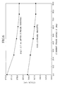
- FIG. 6 shows rising and falling edges of a detected signal of a given phase.
- the data shown in Fig. 6 has been measured based on a reference position signal (Z-phase) provided by a measurement encoder set on a rotor. It is understood from Fig. 6 that phase angle changes between 0° and 90° at a constant current (2000 rpm, 50 A) influences the rising and falling edges such that the edges advance as the current phase advances.
- a sector angle ⁇ of the magnetic piece 25 (Fig. 5) is set at 42°(corresponding to an electrical phase angle of 168°) in the example of Fig.
- a correction data map is used.
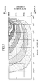
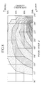
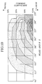
- Figs. 17A and 17B and Figs. 9 and 10 show correction data maps for power-running operation and regenerative operation with the rotor 17 being provided with the magnetic pieces 25.
- the correction data maps are stored in the pole position computing unit 2.
- the current detector 3(3U, 3V, and 3W) detects currents
- the 3-phase-to-2-phase converter 4 converts the three-phase currents into two-phase currents Id and Iq
- the magnetic sensors 27 detect a phase angle ⁇ .
- the unit 2 refers to the data maps and determines a correction quantity ⁇ .
- the unit 2 computes a correct phase angle ⁇ re for calculating current values and a correct phase angle ⁇ re' for calculating PWM command voltages and supplies the correct phase angles ⁇ re and ⁇ re' to the 3-phase-to-2-phase converter 4 and 2-phase-to-3-phase converter 6, respectively.
- the correction carried out by the pole position computing unit 2 will be explained in detail with reference to Figs. 9 to 14. Operation intervals of the pole position computing unit 2 are dependent on the performance of a related CPU, and in this embodiment, are 100 ⁇ sec.
- the pole position computing unit 2 computes a phase angle (base pole position) ⁇ according to a table of Fig. 13 and stores the computed phase angle.
- the unit 2 finds a state transition time t1 and a computation time t2 shown in Fig. 11 according to an incorporated clock and stores the times t1 and t2. These are carried out in steps S05 to S15 of Fig. 12.
- the pole position computing unit 2 computes a phase angle ⁇ re for current phase conversion and a phase angle ⁇ re' for PWM control, this is carried out in step S20 of Fig. 12.
- the pole position computing unit 2 Based on actual current values and the phase angles ⁇ re and ⁇ re', the pole position computing unit 2 refers to the data map of Figs. 17A and 17B to find a correction angle ⁇ and corrects the phase angles ⁇ re and ⁇ re'.
- the corrected phase angles ⁇ re and ⁇ re' are supplied to the 3-phase-to-2-phase converter 4 and 2-hase-to-3-phase converter 6, respectively. These are carried out in step S25 of Fig. 12.
- step S20 using the times t1 and t2 precisely estimate a phase angle (pole position) of the rotor 17, and an example value 150 ⁇ s used in step S20 is determined according to a delay in the power converter 7.
- the pole position detector corrects a phase angle (pole position) ⁇ detected by the magnetic sensors 27 by a deviation ⁇ , to always provide a correct pole position.
- the present invention may limit an electrical angle correction quantity applied to a detected pole position below a value obtained by dividing the circumferential angle of a gap 28 (Fig. 5) between the adjacent magnetic pieces 25 by the number of magnetic poles. This leads to minimize a correction quantity while securing the correctness of pole position (rotation angle) detection.
- the embodiment mentioned above arranges the magnetic pieces 25 along the periphery of the magnet rotor 17 to collect magnetic flux and make rising and falling edges detected by the magnetic sensors 27 steep.
- the present invention is also applicable to motors without magnetic pieces 25.
- data maps of Figs. 18A and 18B are used to correct a detected pole position.
- a pole position detector for a motor according to the second embodiment of the present invention will be explained with reference to Figs. 15 and 16.
- the second embodiment employs a magnetic material that rotates in synchronization with the rotational output of the motor 1.
- an auxiliary gear 31 is attached to an output shaft of the motor 1, and a magnetic sensor 27 is arranged in the vicinity of the gear 31.
- the magnetic sensor 27 may incorporate a magnetic material for collecting magnetic flux.
- One tooth 32, which may correspond to a phase angle of the motor 1 as 0 degree, on the gear 31 may have a width D1 that is different from a width D2 of other teeth 33, so that a reference position may easily be detected.
- the gear 31 may have 12 tooth corresponding to 12 magnetic poles.
- a control technique of this embodiment is the same as that of the first embodiment.
- the second embodiment finds a base pole position (phase angle, or rotation angle) ⁇ from the waveform of a signal provided by the magnetic sensor 27, finds a correction quantity for canceling the influence of stator current from experimentally obtained data maps such as those of Figs. 18A and 18B, and correctly determines pole positions ⁇ re and ⁇ re'.
- the second embodiment realizes large degree of freedom for a location to install the magnetic sensor 27.
Landscapes
- Engineering & Computer Science (AREA)
- Power Engineering (AREA)
- Control Of Motors That Do Not Use Commutators (AREA)
- Brushless Motors (AREA)
Abstract
Description
Claims (6)
- A pole position detector for a motor, comprising:detector of magnetic changes caused by rotation of a rotor of the motor or by rotation of a rotational member linked with the rotor; andcomputation unit, the computation unit detecting a base pole position of the rotor according to the detected magnetic changes, and correcting the base pole position according to the detected base pole position, a stator current magnitude, and a current phase.
- A pole position detector for a motor, comprising:a magnetic sensor configured to sense magnetic flux from a magnet rotor, the magnet rotor having plurality of magnets that are oppositely magnetized one after another; anda computation unit configured to detect a base pole position of the magnet rotor according to changes in the output of the magnetic sensor, detect stator current magnitude and a current phase, and correct the detected base pole position according to the detected base pole position, the stator current magnitude, and the current phase.
- The pole position detector of claim 2, wherein:the magnet rotor has magnetic pieces on an end face thereof that crosses a shaft of the magnet rotor;each of the magnetic pieces is magnetized by magnetic flux from a corresponding one of the magnets; andthe magnetic sensor is fixed to a casing to face the magnetic pieces.
- The pole position detector of claim 2, wherein the computation unit detects the base pole position according to one of rising and falling edges contained in the output of the magnetic sensor.
- The pole position detector of claim 4, wherein the computation unit limits an electrical angle correction quantity applied to the base pole position below a value obtained by dividing the circumferential angle of a gap between the adjacent magnetic pieces by the number of magnetic poles.
- A detecting method of pole position for a motor, comprising:detecting magnetic changes caused by rotation of a rotor of the motor or by rotation of a rotational member linked with the rotor;detecting a base pole position of the rotor according to the detected magnetic changes; andcorrecting the detected base pole position according to the detected base pole position, a stalor current magnitude, and a current phase.
Applications Claiming Priority (2)
| Application Number | Priority Date | Filing Date | Title |
|---|---|---|---|
| JP2000210085A JP3546817B2 (en) | 2000-07-11 | 2000-07-11 | Magnetic pole position detection device for motor |
| JP2000210085 | 2000-07-11 |
Publications (2)
| Publication Number | Publication Date |
|---|---|
| EP1172925A2 true EP1172925A2 (en) | 2002-01-16 |
| EP1172925A3 EP1172925A3 (en) | 2003-07-09 |
Family
ID=18706400
Family Applications (1)
| Application Number | Title | Priority Date | Filing Date |
|---|---|---|---|
| EP01113821A Withdrawn EP1172925A3 (en) | 2000-07-11 | 2001-06-06 | Pole position detector for motor |
Country Status (3)
| Country | Link |
|---|---|
| US (1) | US6713981B2 (en) |
| EP (1) | EP1172925A3 (en) |
| JP (1) | JP3546817B2 (en) |
Cited By (5)
| Publication number | Priority date | Publication date | Assignee | Title |
|---|---|---|---|---|
| WO2006010864A3 (en) * | 2004-06-30 | 2006-08-03 | Valeo Equip Electr Moteur | Device for controlling a rotating electrical machine |
| GB2432057A (en) * | 2005-11-08 | 2007-05-09 | Ferranti Meters Ltd Denis | Brushless motor with rotor flux leakage derived control signals |
| FR2931598A1 (en) * | 2008-05-23 | 2009-11-27 | Valeo Equip Electr Moteur | DEVICE FOR DETERMINING THE ANGULAR POSITION OF A ROTOR OF A POLYPHASE ROTARY ELECTRIC MACHINE AND ROTATING ELECTRIC MACHINE COMPRISING SUCH A DEVICE |
| CN102401626A (en) * | 2011-11-20 | 2012-04-04 | 中国科学院光电技术研究所 | A Method for Estimating Installation Deviation of Rotor Position Sensor of Permanent Magnet Synchronous Motor |
| CN115912798A (en) * | 2022-11-24 | 2023-04-04 | 山东天瑞重工有限公司 | A motor speed detection system, a motor |
Families Citing this family (27)
| Publication number | Priority date | Publication date | Assignee | Title |
|---|---|---|---|---|
| JP3854244B2 (en) * | 2003-05-16 | 2006-12-06 | 株式会社東芝 | Permanent magnet motor and X-ray computed tomography apparatus |
| JP4241218B2 (en) * | 2003-06-27 | 2009-03-18 | 株式会社日立産機システム | AC motor control device and AC motor system |
| US20060055259A1 (en) * | 2004-09-14 | 2006-03-16 | Casey Hanlon | Fault-tolerant magnetic bearing position sensing and control system |
| JP2007049862A (en) * | 2005-08-12 | 2007-02-22 | Hitachi Ltd | Electric machine with built-in magnetic pole position sensor, electric machine apparatus, and in-vehicle electric system |
| JP4434184B2 (en) * | 2006-08-17 | 2010-03-17 | アイシン・エィ・ダブリュ株式会社 | Method and apparatus for feedback control of electric motor |
| US8570028B2 (en) * | 2007-05-10 | 2013-10-29 | Cambridge Integrated Circuits Limited | Transducer for a position sensor |
| JP2010035287A (en) * | 2008-07-25 | 2010-02-12 | Hitachi Ltd | Cylindrical linear motor, and electromagnetic suspension and motor-driven power steering device using the same |
| FI20095986A0 (en) * | 2009-09-25 | 2009-09-25 | Kone Corp | Measuring system, electric drive and elevator system |
| JP4921617B2 (en) * | 2010-03-03 | 2012-04-25 | パナソニック株式会社 | Magnetic pulsation motor |
| JP5661340B2 (en) * | 2010-06-10 | 2015-01-28 | キヤノン株式会社 | Drive device |
| JP5456608B2 (en) * | 2010-07-20 | 2014-04-02 | トヨタ自動車株式会社 | Motor control device and control method |
| GB2488389C (en) | 2010-12-24 | 2018-08-22 | Cambridge Integrated Circuits Ltd | Position sensing transducer |
| WO2012134482A1 (en) * | 2011-03-31 | 2012-10-04 | Otis Elevator Company | Optics based sensor device |
| US9800123B2 (en) | 2012-03-05 | 2017-10-24 | Zhejiang Yilida Ventilator Co., Ltd. | Method for modifying stator tooth top arc of brushless DC motor |
| GB2503006B (en) | 2012-06-13 | 2017-08-09 | Cambridge Integrated Circuits Ltd | Position sensing transducer |
| KR20140076039A (en) * | 2012-12-12 | 2014-06-20 | 한국전자통신연구원 | Motor driving module, operating method for the same, and brushless dc motor system |
| JP2014124000A (en) * | 2012-12-20 | 2014-07-03 | Canon Inc | Control device for actuator |
| JP2015136237A (en) * | 2014-01-17 | 2015-07-27 | 株式会社安川電機 | Dynamo-electric machine controller, dynamo-electric machine control method, and creation method of control map |
| CN107251404B (en) | 2015-01-23 | 2019-08-16 | 三菱电机株式会社 | Control device for AC rotating electrical machine |
| JP6518090B2 (en) * | 2015-03-11 | 2019-05-22 | 株式会社Soken | Rotation angle detection device |
| EP3073622B1 (en) * | 2015-03-25 | 2017-05-03 | Lakeview Innovation Ltd. | Electronically commutated electric motor with direct sampling of the magnetic field of the rotor |
| CN113401772A (en) * | 2016-06-15 | 2021-09-17 | 上海三菱电梯有限公司 | Elevator traction machine |
| WO2018148651A1 (en) | 2017-02-13 | 2018-08-16 | Milwaukee Electric Tool Corporation | Brushless direct current motor for power tools |
| CN107161837A (en) * | 2017-06-05 | 2017-09-15 | 浙江西子富沃德电机有限公司 | A kind of drive system of escalator or moving sidewalk |
| CN107140513A (en) * | 2017-06-05 | 2017-09-08 | 浙江西子富沃德电机有限公司 | A kind of improved escalator or moving sidewalk and its driving main frame |
| US11699967B2 (en) * | 2021-03-09 | 2023-07-11 | GM Global Technology Operations LLC | Electric machine with integrated point field detectors and system for multi-parameter sensing |
| CN115586436B (en) * | 2022-10-18 | 2025-08-22 | 重庆邮电大学 | High-resolution position detection method for permanent magnet linear motor based on magnetic sensor array |
Family Cites Families (17)
| Publication number | Priority date | Publication date | Assignee | Title |
|---|---|---|---|---|
| US4086519A (en) * | 1977-02-25 | 1978-04-25 | Electro-Craft Corporation | Hall effect shaft angle position encoder |
| CN1172839C (en) * | 1997-03-18 | 2004-10-27 | 三菱电机株式会社 | Lifting device for elevator |
| US4785242A (en) * | 1986-12-15 | 1988-11-15 | Sundstrand Corporation | Position detecting apparatus using multiple magnetic sensors for determining relative and absolute angular position |
| JPH08107694A (en) * | 1994-10-05 | 1996-04-23 | Toshiba Corp | Synchronous motor controller |
| JPH08308292A (en) * | 1995-05-01 | 1996-11-22 | Fuji Electric Co Ltd | Magnetic pole position signal error detection circuit and magnetic pole position signal error correction circuit of permanent magnet type synchronous motor |
| JP3315847B2 (en) | 1995-10-27 | 2002-08-19 | 株式会社日立製作所 | Magnetic pole position detecting device and brushless DC motor driving device using the same |
| JP3700305B2 (en) * | 1996-04-19 | 2005-09-28 | 松下電器産業株式会社 | Brushless motor driving device and motor rotor position detecting device |
| JP3317479B2 (en) * | 1996-11-13 | 2002-08-26 | ミネベア株式会社 | Stepping motor |
| JP2858692B2 (en) * | 1996-12-05 | 1999-02-17 | 株式会社安川電機 | Sensorless control method and device for permanent magnet type synchronous motor |
| JP3401155B2 (en) * | 1997-02-14 | 2003-04-28 | 株式会社日立製作所 | Synchronous motor control device and electric vehicle |
| JP3346223B2 (en) * | 1997-06-10 | 2002-11-18 | 株式会社日立製作所 | Motor control method and motor control system |
| GB9716658D0 (en) * | 1997-08-07 | 1997-10-15 | Lucas Ind Plc | Improvements relating to motors |
| JPH11215881A (en) * | 1997-10-27 | 1999-08-06 | Matsushita Electric Ind Co Ltd | Motor control device |
| AUPP098497A0 (en) * | 1997-12-17 | 1998-01-15 | Bishop Innovation Pty Limited | Transmission path torque transducer |
| JP3604563B2 (en) | 1998-07-15 | 2004-12-22 | 株式会社名機製作所 | Malfunction detection method for multi-stage press system |
| US6172498B1 (en) * | 1998-09-29 | 2001-01-09 | Rockwell Technologies, Llc | Method and apparatus for rotor angle detection |
| JP3408468B2 (en) * | 1999-09-07 | 2003-05-19 | ファナック株式会社 | Method for detecting rotor magnetic pole position of synchronous motor |
-
2000
- 2000-07-11 JP JP2000210085A patent/JP3546817B2/en not_active Expired - Fee Related
-
2001
- 2001-06-06 EP EP01113821A patent/EP1172925A3/en not_active Withdrawn
- 2001-07-11 US US09/902,100 patent/US6713981B2/en not_active Expired - Fee Related
Cited By (9)
| Publication number | Priority date | Publication date | Assignee | Title |
|---|---|---|---|---|
| WO2006010864A3 (en) * | 2004-06-30 | 2006-08-03 | Valeo Equip Electr Moteur | Device for controlling a rotating electrical machine |
| US7944168B2 (en) | 2004-06-30 | 2011-05-17 | Valeo Equipements Electriques Moteur | Device for controlling a rotating electrical machine |
| GB2432057A (en) * | 2005-11-08 | 2007-05-09 | Ferranti Meters Ltd Denis | Brushless motor with rotor flux leakage derived control signals |
| FR2931598A1 (en) * | 2008-05-23 | 2009-11-27 | Valeo Equip Electr Moteur | DEVICE FOR DETERMINING THE ANGULAR POSITION OF A ROTOR OF A POLYPHASE ROTARY ELECTRIC MACHINE AND ROTATING ELECTRIC MACHINE COMPRISING SUCH A DEVICE |
| US8078425B2 (en) | 2008-05-23 | 2011-12-13 | Valeo Equipements Electriques Moteur | Device for detecting the angular position of a rotor of a polyphase rotary electrical machine and rotary electrical machine containing such a device |
| EP2124327A3 (en) * | 2008-05-23 | 2016-02-24 | Valeo Equipements Electriques Moteur | Device for determining the angular position of a rotor of a multi-phase rotating electric machine and rotating electric machine comprising such a device |
| CN102401626A (en) * | 2011-11-20 | 2012-04-04 | 中国科学院光电技术研究所 | A Method for Estimating Installation Deviation of Rotor Position Sensor of Permanent Magnet Synchronous Motor |
| CN102401626B (en) * | 2011-11-20 | 2013-11-20 | 中国科学院光电技术研究所 | Method for estimating mounting deviation of permanent magnet synchronous motor rotor position sensor |
| CN115912798A (en) * | 2022-11-24 | 2023-04-04 | 山东天瑞重工有限公司 | A motor speed detection system, a motor |
Also Published As
| Publication number | Publication date |
|---|---|
| JP3546817B2 (en) | 2004-07-28 |
| US20020011814A1 (en) | 2002-01-31 |
| JP2002034278A (en) | 2002-01-31 |
| US6713981B2 (en) | 2004-03-30 |
| EP1172925A3 (en) | 2003-07-09 |
Similar Documents
| Publication | Publication Date | Title |
|---|---|---|
| US6713981B2 (en) | Pole position detector for motor | |
| US10447186B2 (en) | Linear hall device based field oriented control motor drive system | |
| US8471506B2 (en) | Motor control apparatus | |
| KR102588927B1 (en) | Motor control method | |
| CN103098366B (en) | Phase shift detection device, motor drive device, brushless motor, and phase shift detection method | |
| EP2771204B1 (en) | Electric motor or generator system | |
| US20170353130A1 (en) | Device for correcting hall sensor installation position error of bldc motor having linear hall sensor, and method thereof | |
| EP3982089B1 (en) | Magnetic sensor system for motor control | |
| JP2001119914A (en) | Motor rotor position detection device | |
| US20040251860A1 (en) | Advanced sensorless drive technique for brushless DC motors | |
| JP7291104B2 (en) | Three-phase brushless motor and method for detecting rotational position of three-phase brushless motor | |
| EP1444774B1 (en) | Motor controller | |
| KR20110016573A (en) | Rotor position sensor | |
| JPH1118499A (en) | Sensorless speed control method for permanent magnet type synchronous motor and method for detecting step-out thereof | |
| JP2022131446A (en) | motor controller | |
| EP3599714A1 (en) | Method for determining the rotor position of a bldc motor | |
| JP5396754B2 (en) | Output estimation device | |
| Konghirun | Automatic offset calibration of quadrature encoder pulse sensor for vector controlled drive of permanent magnet synchronous motors | |
| KR102542785B1 (en) | Apparatus for calibrating rotor position of motor and method thereof | |
| JPH0854205A (en) | Rotational position detector for electric rotating | |
| EP4667865A1 (en) | Rotation angle detection device | |
| WO2026014000A1 (en) | Electric motor control device | |
| JPH0614580A (en) | Motor controller | |
| JP2000298037A (en) | Rotation sensor | |
| JP2007228773A (en) | Motor, motor driving device and motor driving method |
Legal Events
| Date | Code | Title | Description |
|---|---|---|---|
| PUAI | Public reference made under article 153(3) epc to a published international application that has entered the european phase |
Free format text: ORIGINAL CODE: 0009012 |
|
| 17P | Request for examination filed |
Effective date: 20010606 |
|
| AK | Designated contracting states |
Kind code of ref document: A2 Designated state(s): AT BE CH CY DE DK ES FI FR GB GR IE IT LI LU MC NL PT SE TR |
|
| AX | Request for extension of the european patent |
Free format text: AL;LT;LV;MK;RO;SI |
|
| PUAL | Search report despatched |
Free format text: ORIGINAL CODE: 0009013 |
|
| AK | Designated contracting states |
Designated state(s): AT BE CH CY DE DK ES FI FR GB GR IE IT LI LU MC NL PT SE TR |
|
| AX | Request for extension of the european patent |
Extension state: AL LT LV MK RO SI |
|
| AKX | Designation fees paid |
Designated state(s): DE FR GB |
|
| STAA | Information on the status of an ep patent application or granted ep patent |
Free format text: STATUS: THE APPLICATION IS DEEMED TO BE WITHDRAWN |
|
| 18D | Application deemed to be withdrawn |
Effective date: 20080103 |