EP1172913A2 - Steuereinheit für elektrische Anlagen mit verbesserter Kabelanordnung - Google Patents
Steuereinheit für elektrische Anlagen mit verbesserter Kabelanordnung Download PDFInfo
- Publication number
- EP1172913A2 EP1172913A2 EP01115434A EP01115434A EP1172913A2 EP 1172913 A2 EP1172913 A2 EP 1172913A2 EP 01115434 A EP01115434 A EP 01115434A EP 01115434 A EP01115434 A EP 01115434A EP 1172913 A2 EP1172913 A2 EP 1172913A2
- Authority
- EP
- European Patent Office
- Prior art keywords
- control unit
- electrical systems
- box
- cross
- shaped body
- Prior art date
- Legal status (The legal status is an assumption and is not a legal conclusion. Google has not performed a legal analysis and makes no representation as to the accuracy of the status listed.)
- Granted
Links
Images
Classifications
-
- H—ELECTRICITY
- H02—GENERATION; CONVERSION OR DISTRIBUTION OF ELECTRIC POWER
- H02G—INSTALLATION OF ELECTRIC CABLES OR LINES, OR OF COMBINED OPTICAL AND ELECTRIC CABLES OR LINES
- H02G3/00—Installations of electric cables or lines or protective tubing therefor in or on buildings, equivalent structures or vehicles
- H02G3/26—Installations of cables, lines, or separate protective tubing therefor directly on or in walls, ceilings, or floors
Definitions
- the present invention relates to control units for electrical systems, and in particular to a control unit in which the arrangement of the cables within it is highly improved.
- Control units for electrical systems which are marketed at present, in particular for small and medium electrical systems for domestic use, consist of a box-shaped body containing support means, commonly cross-pieces made of metal or similar materials, on which the components of the control unit are placed. Said cross-pieces can be fastened directly to the bottom of the box-shaped body, or they can be mounted on support elements which are in their turn suitably connected with the bottom of said box-shaped body.
- the cables for the connection of the system with its elements within the control unit, as well as for other connections between said elements usually fill the remaining room within the box-shaped body. It is obvious that their casual or untidy arrangement can result in huge problems related to the operation and maintenance of the electrical system.
- the present invention therefore aims at providing a control unit in which the cable arrangement within the latter is improved, so as to simplify the connection both between the system and the elements of the control unit and between the elements of the control unit itself.
- the object of the present invention is therefore a control unit for electrical systems, comprising a box-shaped body on whose bottom wall at least one cross-piece is arranged for mounting the control unit elements, said cross-piece being placed on two supports which are perpendicular to it and which are connected to said bottom wall of said box-shaped body, characterized in that at least one of said supports comprises a device for the distribution of cables within said control unit.
- Said distribution device can comprise a distribution channel consisting of two series of plates suitably placed at the same distance, substantially L-shaped, located on planes which are perpendicular to the plane of the bottom wall of said box-shaped body, opposed one to the other so as to form said channel, and connected through at least a continuous element.
- the distribution device can be obtained as one piece with the cross-piece support, or it can be connected to said support through suitable means.
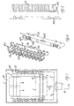
- Figure 1 shows a form of embodiment of the control unit according to the present invention
- the numeral 1 indicates the box-shaped body of the control unit, which is shown in this figure without its top cover.
- the cross-pieces 3 on which the elements, i.e. the components, 5 and 6 within the control unit are located, are positioned on the supports 2, which comprise distribution devices 102 consisting of the plates 112, for the distribution of the cables 11 coming from the cableway 10.
- the distribution device 102 also contains the cable 12 for the connection between the element 5 and an element 6.
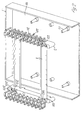
- FIG. 2 shows the control unit according to the invention in an exploded perspective view.
- the bottom wall 101 of the box-shaped body 1 contains the pegs 111 protruding towards the inside of the body 1, said pegs being coupled with the through holes 502 formed on the supports 2.
- the cross-pieces 3 in case of metal draw pieces, are connected on their ends with the supports 2 by introducing the pins 202 protruding from the supports 2 into the holes 203 of said cross-pieces; moreover, it is also provided for fastening means 103, screws for instance, which are inserted into the holes 212.
- Each support 2 further comprises a device 102 for the distribution of cables within the control unit.
- said device consists of a distribution channel 102 made of two series of plates 112, 122, substantially L-shaped, which are not aligned one to the other and which are arranged on planes perpendicular to the bottom wall 101 of the body 1, and with an end connected to said support 2.
- the free end of said plates 122 is folded inside, so as to simplify the introduction of the cables into the distribution device 102, and simultaneously to ensure their positioning.
- the support 2 with its distribution device 102 is shown in Figure 3, where it can be observed that the pins 302 turned towards the bottom wall 101 of the body 1 enable an alternative position for fastening the cross-pieces 3.
- Figure 4 shows an execution variant of the support used in the control unit according to the present invention.
- the support 2 is provided with longitudinal slits 402 apt to cooperate with the strips 124 protruding from the plate 4 on which the distribution device 104 is obtained, said device consisting, analogously to the above-described device 102, of two series of plates 114, 124 having the same characteristics of the plates 112, 122 described above.
- the strips 124 show on the lateral rims of their free ends the toothed protuberances 134 ensuring the blocking of said strips 124 within the slits 402.
- the control unit for electrical systems will be evident from the following.
- the cross-pieces 3 are fastened to the supports 2 in the reciprocal positions which are most suitable for the arrangement of the components 5, 6 within the control unit, and the supports 2 are in their turn connected with the bottom wall 101 of the box-shaped body 1 of the control unit; now, the components 5, 6 are positioned on the cross-pieces as shown in Figure 1, and are connected with the cables 11 of the system, and if possible one to the other for instance by means of the cable 12.
- the cables 11, 12 are all arranged within the distribution devices 102, thus enabling a more rational organization of the central chamber of the control unit, which simplifies installation and maintenance operations.
- the distribution devices can be carried out separately from the supports 2, as shown in the execution variant of Figure 4, though being firmly connectable to the latter.
Landscapes
- Engineering & Computer Science (AREA)
- Architecture (AREA)
- Civil Engineering (AREA)
- Structural Engineering (AREA)
- Patch Boards (AREA)
- Selective Calling Equipment (AREA)
- Insertion, Bundling And Securing Of Wires For Electric Apparatuses (AREA)
Applications Claiming Priority (2)
| Application Number | Priority Date | Filing Date | Title |
|---|---|---|---|
| ITGE20000025 IT250799Y1 (it) | 2000-07-14 | 2000-07-14 | Centralina per impianti elettrici con disposizione migliorata dei cavi al suo interno. |
| ITGE000025U | 2000-07-14 |
Publications (3)
| Publication Number | Publication Date |
|---|---|
| EP1172913A2 true EP1172913A2 (de) | 2002-01-16 |
| EP1172913A3 EP1172913A3 (de) | 2003-05-14 |
| EP1172913B1 EP1172913B1 (de) | 2005-10-19 |
Family
ID=11442591
Family Applications (1)
| Application Number | Title | Priority Date | Filing Date |
|---|---|---|---|
| EP20010115434 Expired - Lifetime EP1172913B1 (de) | 2000-07-14 | 2001-06-27 | Steuereinheit für elektrische Anlagen mit verbesserter Kabelanordnung |
Country Status (4)
| Country | Link |
|---|---|
| EP (1) | EP1172913B1 (de) |
| DE (1) | DE60114095T2 (de) |
| IT (1) | IT250799Y1 (de) |
| RU (1) | RU2001119482A (de) |
Family Cites Families (2)
| Publication number | Priority date | Publication date | Assignee | Title |
|---|---|---|---|---|
| DE2546176C2 (de) * | 1975-10-15 | 1984-09-27 | Brown, Boveri & Cie Ag, 6800 Mannheim | Gehäuse für eine isolierstoffgekapselte Schaltanlage für Schalt-, Steuer- und Regeleinrichtungen mit in Kastenelementen befestigten Installationsgeräten |
| US5788087A (en) * | 1996-03-18 | 1998-08-04 | Ortronics, Inc. | Hinged wire management panel assembly |
-
2000
- 2000-07-14 IT ITGE20000025 patent/IT250799Y1/it active
-
2001
- 2001-06-27 DE DE2001614095 patent/DE60114095T2/de not_active Expired - Fee Related
- 2001-06-27 EP EP20010115434 patent/EP1172913B1/de not_active Expired - Lifetime
- 2001-07-13 RU RU2001119482/09A patent/RU2001119482A/ru not_active Application Discontinuation
Also Published As
| Publication number | Publication date |
|---|---|
| EP1172913B1 (de) | 2005-10-19 |
| IT250799Y1 (it) | 2003-10-14 |
| ITGE20000025V0 (it) | 2000-07-14 |
| ITGE20000025U1 (it) | 2002-01-14 |
| EP1172913A3 (de) | 2003-05-14 |
| DE60114095T2 (de) | 2006-07-20 |
| RU2001119482A (ru) | 2003-06-27 |
| DE60114095D1 (de) | 2005-11-24 |
Similar Documents
| Publication | Publication Date | Title |
|---|---|---|
| US3049688A (en) | Portable electrical receptacle box | |
| CA2654658C (en) | Modular bus assembly for a loadcenter | |
| FI97097B (fi) | Laite kaukoviestitystekniikan kytkentälistojen asentamiseksi | |
| US4095864A (en) | Modular manifolding means and system for electrical and/or pneumatic control devices and parts and methods | |
| CA1331474C (en) | Residential load centre with busbar retaining means | |
| US6861189B1 (en) | Back wire ground clamp | |
| US3950053A (en) | Assembling unit for modular electrical apparatus | |
| US6126296A (en) | Adjustable ceiling and wall cover plate | |
| US7576284B2 (en) | Gangable electrical bracket | |
| US7108532B2 (en) | Circuit selectable receptacle | |
| US20080026621A1 (en) | Circuit selectable receptacle | |
| EP1172913B1 (de) | Steuereinheit für elektrische Anlagen mit verbesserter Kabelanordnung | |
| EA011702B1 (ru) | Вспомогательная опорная рамка для по меньшей мере одной единицы электрооборудования | |
| US2932000A (en) | Housing unit and mounting means | |
| GB2214713A (en) | Electrical consumer units | |
| US2897410A (en) | Plug-in type circuit breaker panelboard | |
| GB2214714A (en) | Electrical consumer units | |
| US10530093B2 (en) | Cable strain relief and shield fastening in a plug connector housing | |
| AU2004246336B2 (en) | Distribution board, especially small distribution board | |
| EP0573254A1 (de) | Gehäuse für Steuereinheit | |
| US2863935A (en) | Terminal board for junction or outlet box | |
| DE202005017605U1 (de) | Fernauslösbarer ein- oder mehrpoliger Stromabschalter | |
| US3114792A (en) | Wiring device assembly | |
| ATE257931T1 (de) | Verkleidung für einen plattenheizkörper mit aussenliegendem betätigungselement | |
| FR2761568B3 (fr) | Dispositif de blocage de cables sur un dispositif d'installation electrique tel qu'un coffret ou une armoire de repartition ou de comptage |
Legal Events
| Date | Code | Title | Description |
|---|---|---|---|
| PUAI | Public reference made under article 153(3) epc to a published international application that has entered the european phase |
Free format text: ORIGINAL CODE: 0009012 |
|
| AK | Designated contracting states |
Kind code of ref document: A2 Designated state(s): AT BE CH CY DE DK ES FI FR GB GR IE IT LI LU MC NL PT SE TR |
|
| AX | Request for extension of the european patent |
Free format text: AL;LT;LV;MK;RO;SI |
|
| PUAL | Search report despatched |
Free format text: ORIGINAL CODE: 0009013 |
|
| AK | Designated contracting states |
Designated state(s): AT BE CH CY DE DK ES FI FR GB GR IE IT LI LU MC NL PT SE TR |
|
| AX | Request for extension of the european patent |
Extension state: AL LT LV MK RO SI |
|
| 17P | Request for examination filed |
Effective date: 20030528 |
|
| AKX | Designation fees paid |
Designated state(s): DE FR IT |
|
| GRAP | Despatch of communication of intention to grant a patent |
Free format text: ORIGINAL CODE: EPIDOSNIGR1 |
|
| RIN1 | Information on inventor provided before grant (corrected) |
Inventor name: MESSERI, MASSIMOC/O BOCCHIOTTI SOCIETAE PER I.E. |
|
| GRAS | Grant fee paid |
Free format text: ORIGINAL CODE: EPIDOSNIGR3 |
|
| GRAA | (expected) grant |
Free format text: ORIGINAL CODE: 0009210 |
|
| RAP1 | Party data changed (applicant data changed or rights of an application transferred) |
Owner name: BOCCHIOTTI S.P.A. |
|
| AK | Designated contracting states |
Kind code of ref document: B1 Designated state(s): DE FR IT |
|
| PG25 | Lapsed in a contracting state [announced via postgrant information from national office to epo] |
Ref country code: IT Free format text: LAPSE BECAUSE OF FAILURE TO SUBMIT A TRANSLATION OF THE DESCRIPTION OR TO PAY THE FEE WITHIN THE PRESCRIBED TIME-LIMIT;WARNING: LAPSES OF ITALIAN PATENTS WITH EFFECTIVE DATE BEFORE 2007 MAY HAVE OCCURRED AT ANY TIME BEFORE 2007. THE CORRECT EFFECTIVE DATE MAY BE DIFFERENT FROM THE ONE RECORDED. Effective date: 20051019 |
|
| REF | Corresponds to: |
Ref document number: 60114095 Country of ref document: DE Date of ref document: 20051124 Kind code of ref document: P |
|
| ET | Fr: translation filed | ||
| PLBE | No opposition filed within time limit |
Free format text: ORIGINAL CODE: 0009261 |
|
| 26N | No opposition filed |
Effective date: 20060720 |
|
| PGFP | Annual fee paid to national office [announced via postgrant information from national office to epo] |
Ref country code: DE Payment date: 20070419 Year of fee payment: 7 |
|
| PGFP | Annual fee paid to national office [announced via postgrant information from national office to epo] |
Ref country code: FR Payment date: 20070510 Year of fee payment: 7 |
|
| REG | Reference to a national code |
Ref country code: FR Ref legal event code: ST Effective date: 20090228 |
|
| PG25 | Lapsed in a contracting state [announced via postgrant information from national office to epo] |
Ref country code: DE Free format text: LAPSE BECAUSE OF NON-PAYMENT OF DUE FEES Effective date: 20090101 |
|
| PG25 | Lapsed in a contracting state [announced via postgrant information from national office to epo] |
Ref country code: FR Free format text: LAPSE BECAUSE OF NON-PAYMENT OF DUE FEES Effective date: 20080630 |