EP1172835A2 - Magnetic proximity sensor - Google Patents
Magnetic proximity sensor Download PDFInfo
- Publication number
- EP1172835A2 EP1172835A2 EP01112442A EP01112442A EP1172835A2 EP 1172835 A2 EP1172835 A2 EP 1172835A2 EP 01112442 A EP01112442 A EP 01112442A EP 01112442 A EP01112442 A EP 01112442A EP 1172835 A2 EP1172835 A2 EP 1172835A2
- Authority
- EP
- European Patent Office
- Prior art keywords
- case
- proximity sensor
- magnetic proximity
- sensor according
- phial
- Prior art date
- Legal status (The legal status is an assumption and is not a legal conclusion. Google has not performed a legal analysis and makes no representation as to the accuracy of the status listed.)
- Granted
Links
Images


Classifications
-
- H—ELECTRICITY
- H01—ELECTRIC ELEMENTS
- H01H—ELECTRIC SWITCHES; RELAYS; SELECTORS; EMERGENCY PROTECTIVE DEVICES
- H01H36/00—Switches actuated by change of magnetic field or of electric field, e.g. by change of relative position of magnet and switch, by shielding
- H01H36/0006—Permanent magnet actuating reed switches
- H01H36/0046—Limit switches, also fail-safe operation or anti-tamper considerations
-
- H—ELECTRICITY
- H01—ELECTRIC ELEMENTS
- H01H—ELECTRIC SWITCHES; RELAYS; SELECTORS; EMERGENCY PROTECTIVE DEVICES
- H01H36/00—Switches actuated by change of magnetic field or of electric field, e.g. by change of relative position of magnet and switch, by shielding
- H01H36/0006—Permanent magnet actuating reed switches
- H01H36/0033—Mountings; Housings; Connections
Definitions
- the present invention refers to an improved magnetic proximity sensor.
- Magnetic proximity sensors are generally known in the art to usually comprise a reed phial, the terminal leads of which are connected to a sheathed electric cable coming out, through a sealing cap, of a substantially cylindrical insulating case in which the phial itself is housed.
- the interior of this case is furthermore filled with a resin that is adapted to both ensure full insulation of the component parts and to effectively hold them firmly in place.
- Such a reed phial normally comprises a glass tube which, according to the requirements, may contain at least an electric switch, a break-before-make switch, or the like, which is normally in a resting position (open switch, for instance) and is adapted to change over to an operating condition (closed switch, for instance) when the sensor is approached by a magnetic body.
- Reed phials are largely known to be inherently brittle devices that are quite easily subject to a breakage of the glass tube.
- some applications such as for instance those involving the use of magnetic proximity sensors to control such lifting or hoisting installations as lifts or elevators, in which the reliability of the whole system is of paramount importance, malfunction problems quite often occur to arise due to these sensors being tampered with or used incorrectly by the people in charge of the installation of such apparatuses.
- this incorrect handling of the sensors by the installers has led to a breakage of the glass tube, with substantially unacceptable consequences.
- a further purpose of the present invention is to provide a magnetic proximity sensor of the above cited kind, which has a structure that is substantially simple and capable of being easily assembled.
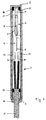
- the magnetic proximity sensor mainly comprises a substantially cylindrical case 1 made of an insulating material such as a plastic material containing a glass filler.
- An outer head end portion 2 of such a case 1 is preferably sealed, whereas at the opposite end portion there is provided with an aperture 3 for the insertion of the component parts thereinto, as this shall be explained in greater detail further on.
- the active part of the sensor is constituted by at least a reed phial 4, which in turn comprises a glass tube 5 housing at least an electric device 6, such as a switch, a break-before-make contact, or the like, which is adapted to switch between a resting condition and an operating condition in a traditional manner.
- said electric device 6 comprises two or more terminal leads 7, 8 which must be connected to respective electric leads 9, 10 that are part of a connection cable 11, which is of a bipolar type in the described example.
- said terminal leads 7, 8 of the reed phial 4 are welded or soldered to respective electric conductors 12, 13 that are provided on a support member 14.
- a support member 14 is formed by a printed-circuit board provided with at least two conductive paths that form the above cited conductors 12, 13. Said welding or soldering of the terminal leads 7, 8 to said paths 12, 13 brings about also the mechanical support of the reed phial 4.
- the board 14 has dimensions that are correlated to the ones of the case 1, into which it is mounted through the aperture 3, so as to be capable of supporting said reed phial 4 in a suspended manner, i.e. without any direct contact of said phial with the case 1.
- the board 14 is mounted in the case 1 without any direct mechanical contact therewith, as this will be described in greater detail further on.
- the end portions of the electric leads 9, 10 are welded or soldered to the respective paths 12, 13 of the board 14, and the cable 11 is supported and centered with respect to the case 1 through the interposition of an elastic ring or grommet 15 of rubber or similar material.
- the latter also ensures an effective insulating action to protect the interior of the case 1 against the penetration of dust, liquids or the like thereinto.
- the cable 11 comes out of the case 1 by passing in an air-tight manner through a sealing cap 16 that is press-fitted mechanically on to the aperture 3.
- said cap 16 is preferably shaped so as to include check means (such as for instance one or more side recesses 19) adapted to snap into engagement with complementary check means (such as for instance one or more protrusions 20) provided on the inner surface of the case 1.
- check means such as for instance one or more side recesses 19
- complementary check means such as for instance one or more protrusions 20
- the board 4 On its side lying near to the sealed end portion 2 of the case 1, the board 4 is shaped so as to feature two opposite undercuts 17, in correspondence of which it is supported and centered with respect to the case 1 through the interposition of a further elastic spacer ring 18, made of rubber or similar material, which protrudes transversally and axially from the board 14.
- the board 14, which in turn supports the reed phial 4 is mounted in the case 1 without any direct contact therewith, neither in correspondence of the sides nor in correspondence of the head or outer end portions thereof.
- said elastic grommets or rings 15 and 18 advantageously act so to say as respective shock and vibration damping means ensuring an additional degree of mechanical strength to the entire magnetic proximity sensor, which is so able to more effectively withstand possible rough or even incorrect handling.
- the reed phial 4 and the respective terminal leads 7, 8 are actually suspended inside the casing 1 and are therefore advantageously protected against those mechanical stresses which are most likely to cause them to break down in traditional solutions.
- the cable 11 may be a three-core cable, in the case that the reed phial 4 is provided with more than two terminal leads, or the end portion 2 of the case 1 may also be of the type sealed with the use of a mechanically press-fitted cap similar to the cap 16.
Landscapes
- Switches That Are Operated By Magnetic Or Electric Fields (AREA)
- Geophysics And Detection Of Objects (AREA)
Abstract
Description
- Figure 1 is a schematical, longitudinal-section view of a preferred embodiment of the present invention;
- Figures 2 and 3 are views of respective enlarged details of the magnetic proximity sensor illustrated in Figure 1;
- Figure 4 is a schematical view of the magnetic proximity sensor as sectioned along a plane that is orthogonal to the section plane of Figure 1; and
- Figure 5 is a view according to the section V-V of the magnetic proximity sensor of Figure 4.
Claims (9)
- Magnetic proximity sensor comprising a case that has at least an insertion aperture and houses at least a reed phial having terminal leads connected to an electric cable coming out of the same case through a cap used to seal said aperture, characterized in that said reed phial (4) is mounted inside said case (1) through the use of support means (14) adapted to keep said phial suspended in said case (1) without any direct mechanical contact therewith.
- Magnetic proximity sensor according to claim 1, characterized in that said support means comprise a printed-circuit board (14) provided with conductive paths (12, 13) to which there are attached respective terminal leads (7, 8) of the reed phial (4), in which said terminal leads are furthermore connected via said conductive paths (12, 13) to respective conductors (9, 10) of the electric cable (11).
- Magnetic proximity sensor according to claim 1, characterized in that said cable (11) comes out of the case (1) through said sealing cap (16) which is mounted by mechanically press-fitting it on to said insertion aperture (3), in which the interior of the case (1) is free of any insulating resin or similar filling material.
- Magnetic proximity sensor according to claim 1, characterized in that said support means (14) are mounted in the case (1) through the use of at least a spacer member (18), so that also these support means (14) are suspended inside the case (1) without any direct mechanical contact therewith.
- Magnetic proximity sensor according to claim 1, characterized in that said cable (11) is supported and centered with respect to the case (1) through the interposition of a spacer member (15).
- Magnetic proximity sensor according to claim 3, characterized in that said sealing cap (16) is shaped so as to include check means (19) adapted to snap into engagement with complementary check means (20) provided on the inner surface of the case (1) in such a manner as to prevent the cap (16) from slipping or coming off accidentally from the same case and/or being able to rotate with respect thereto.
- Magnetic proximity sensor according to claim 4, characterized in that said spacer member (18) is elastic and acts also as a shock and vibration damping member.
- Magnetic proximity sensor according to claim 4, characterized in that said spacer member (18) is provided in correspondence of a shaped end portion (17) of the support means (14), from which it protrudes transversally and axially so as to abut against the case (1).
- Magnetic proximity sensor according to claim 5, characterized in that said spacer member (15) is elastic and also acts not only as a shock and vibration damping member, but also as an insulating member protecting the interior of the case (1) against the infiltration of dust or liquids.
Applications Claiming Priority (2)
| Application Number | Priority Date | Filing Date | Title |
|---|---|---|---|
| IT2000PN000042A ITPN20000042A1 (en) | 2000-07-13 | 2000-07-13 | MAGNETIC PROXIMITY SENSOR |
| ITPN000042 | 2000-07-13 |
Publications (3)
| Publication Number | Publication Date |
|---|---|
| EP1172835A2 true EP1172835A2 (en) | 2002-01-16 |
| EP1172835A3 EP1172835A3 (en) | 2004-03-03 |
| EP1172835B1 EP1172835B1 (en) | 2005-08-31 |
Family
ID=11453165
Family Applications (1)
| Application Number | Title | Priority Date | Filing Date |
|---|---|---|---|
| EP01112442A Expired - Lifetime EP1172835B1 (en) | 2000-07-13 | 2001-05-22 | Magnetic proximity sensor |
Country Status (5)
| Country | Link |
|---|---|
| EP (1) | EP1172835B1 (en) |
| AT (1) | ATE303655T1 (en) |
| DE (1) | DE60113015D1 (en) |
| ES (1) | ES2248190T3 (en) |
| IT (1) | ITPN20000042A1 (en) |
Cited By (2)
| Publication number | Priority date | Publication date | Assignee | Title |
|---|---|---|---|---|
| FR2844393A1 (en) * | 2002-09-11 | 2004-03-12 | Bosch Gmbh Robert | Electric reed bulb switch for a motor vehicle brake reservoir has a support with a mounting structure in the form of a loop or particularly a molded plastic mass that protects the bulb against damage during its in-situ mounting |
| CN112729359A (en) * | 2019-10-28 | 2021-04-30 | K.W.H.自行车运动销售有限公司 | Sensor device |
Family Cites Families (4)
| Publication number | Priority date | Publication date | Assignee | Title |
|---|---|---|---|---|
| US4700163A (en) * | 1986-09-29 | 1987-10-13 | Security Technologies | Removable magnetic switch security system for buildings |
| US5438869A (en) * | 1991-11-26 | 1995-08-08 | C & K Systems, Inc. | Protective reed switch housing |
| GB2298740B (en) * | 1995-03-08 | 1998-07-01 | Eja Eng Plc | Reed switch assembly |
| JPH11111133A (en) * | 1997-10-02 | 1999-04-23 | Tokin Corp | Temperature switch |
-
2000
- 2000-07-13 IT IT2000PN000042A patent/ITPN20000042A1/en unknown
-
2001
- 2001-05-22 EP EP01112442A patent/EP1172835B1/en not_active Expired - Lifetime
- 2001-05-22 ES ES01112442T patent/ES2248190T3/en not_active Expired - Lifetime
- 2001-05-22 AT AT01112442T patent/ATE303655T1/en not_active IP Right Cessation
- 2001-05-22 DE DE60113015T patent/DE60113015D1/en not_active Expired - Lifetime
Cited By (2)
| Publication number | Priority date | Publication date | Assignee | Title |
|---|---|---|---|---|
| FR2844393A1 (en) * | 2002-09-11 | 2004-03-12 | Bosch Gmbh Robert | Electric reed bulb switch for a motor vehicle brake reservoir has a support with a mounting structure in the form of a loop or particularly a molded plastic mass that protects the bulb against damage during its in-situ mounting |
| CN112729359A (en) * | 2019-10-28 | 2021-04-30 | K.W.H.自行车运动销售有限公司 | Sensor device |
Also Published As
| Publication number | Publication date |
|---|---|
| ATE303655T1 (en) | 2005-09-15 |
| EP1172835A3 (en) | 2004-03-03 |
| ES2248190T3 (en) | 2006-03-16 |
| ITPN20000042A1 (en) | 2002-01-13 |
| ITPN20000042A0 (en) | 2000-07-13 |
| EP1172835B1 (en) | 2005-08-31 |
| DE60113015D1 (en) | 2005-10-06 |
Similar Documents
| Publication | Publication Date | Title |
|---|---|---|
| US8366479B2 (en) | Feeder clamp | |
| JP2004517457A (en) | Device for guiding electrical conductors through the wall of a fuel tank | |
| CN102315037B (en) | Push switch | |
| EP1172835B1 (en) | Magnetic proximity sensor | |
| US8148655B2 (en) | Pressure sensor for a hermetically sealed container | |
| JP6463201B2 (en) | Connector and wire harness | |
| US7345571B2 (en) | Thermally-actuated switch | |
| KR102713367B1 (en) | Contact and seperator module | |
| EP0117982B1 (en) | Shock and vibration sensitive switch | |
| JPH0636640A (en) | Sealed snap switch assembly and method of refilling its housing chamber with gas | |
| US20100097235A1 (en) | Explosion Proof Non-Contact Check Point to Mount in Explosion Proof Enclosure | |
| CN1078964C (en) | Electrical component protection device | |
| US4967303A (en) | Surge suppression system for submersible electrical motors | |
| CN218841497U (en) | Remote controller and crane | |
| ES2137667T3 (en) | SEALED PACKING FOR THE ENVIRONMENTAL PROTECTION OF ELECTRONIC COMPONENTS. | |
| CN219041765U (en) | Waterproof static touch switch | |
| US20240049416A1 (en) | Connector for connecting a line to a printed circuit board, housing having such a connector, and assembly comprising a printed circuit board and such a housing | |
| US4167726A (en) | Magnetic liquid protector | |
| CN112242278B (en) | An anti-overheating electronic tube | |
| EP3757459B1 (en) | Device for handling combustion gas | |
| CN212620817U (en) | Sensor housing with novel structure | |
| KR950002900Y1 (en) | Water Flow Detection Switch of Fan Heater | |
| JPH0217953Y2 (en) | ||
| CN210745103U (en) | Magnetic induction button switch | |
| CN1202593C (en) | Impervious removable wiring structure device matched with electric equipment and its application method |
Legal Events
| Date | Code | Title | Description |
|---|---|---|---|
| PUAI | Public reference made under article 153(3) epc to a published international application that has entered the european phase |
Free format text: ORIGINAL CODE: 0009012 |
|
| AK | Designated contracting states |
Kind code of ref document: A2 Designated state(s): AT BE CH CY DE DK ES FI FR GB GR IE IT LI LU MC NL PT SE TR |
|
| AX | Request for extension of the european patent |
Free format text: AL;LT;LV;MK;RO;SI |
|
| PUAL | Search report despatched |
Free format text: ORIGINAL CODE: 0009013 |
|
| AK | Designated contracting states |
Kind code of ref document: A3 Designated state(s): AT BE CH CY DE DK ES FI FR GB GR IE IT LI LU MC NL PT SE TR |
|
| AX | Request for extension of the european patent |
Extension state: AL LT LV MK RO SI |
|
| 17P | Request for examination filed |
Effective date: 20040729 |
|
| 17Q | First examination report despatched |
Effective date: 20040901 |
|
| AKX | Designation fees paid |
Designated state(s): AT BE CH CY DE DK ES FI FR GB GR IE IT LI LU MC NL PT SE TR |
|
| GRAP | Despatch of communication of intention to grant a patent |
Free format text: ORIGINAL CODE: EPIDOSNIGR1 |
|
| GRAS | Grant fee paid |
Free format text: ORIGINAL CODE: EPIDOSNIGR3 |
|
| GRAA | (expected) grant |
Free format text: ORIGINAL CODE: 0009210 |
|
| AK | Designated contracting states |
Kind code of ref document: B1 Designated state(s): AT BE CH CY DE DK ES FI FR GB GR IE IT LI LU MC NL PT SE TR |
|
| PG25 | Lapsed in a contracting state [announced via postgrant information from national office to epo] |
Ref country code: CH Free format text: LAPSE BECAUSE OF FAILURE TO SUBMIT A TRANSLATION OF THE DESCRIPTION OR TO PAY THE FEE WITHIN THE PRESCRIBED TIME-LIMIT Effective date: 20050831 Ref country code: BE Free format text: LAPSE BECAUSE OF FAILURE TO SUBMIT A TRANSLATION OF THE DESCRIPTION OR TO PAY THE FEE WITHIN THE PRESCRIBED TIME-LIMIT Effective date: 20050831 Ref country code: LI Free format text: LAPSE BECAUSE OF FAILURE TO SUBMIT A TRANSLATION OF THE DESCRIPTION OR TO PAY THE FEE WITHIN THE PRESCRIBED TIME-LIMIT Effective date: 20050831 Ref country code: FI Free format text: LAPSE BECAUSE OF FAILURE TO SUBMIT A TRANSLATION OF THE DESCRIPTION OR TO PAY THE FEE WITHIN THE PRESCRIBED TIME-LIMIT Effective date: 20050831 Ref country code: NL Free format text: LAPSE BECAUSE OF FAILURE TO SUBMIT A TRANSLATION OF THE DESCRIPTION OR TO PAY THE FEE WITHIN THE PRESCRIBED TIME-LIMIT Effective date: 20050831 Ref country code: AT Free format text: LAPSE BECAUSE OF FAILURE TO SUBMIT A TRANSLATION OF THE DESCRIPTION OR TO PAY THE FEE WITHIN THE PRESCRIBED TIME-LIMIT Effective date: 20050831 |
|
| REG | Reference to a national code |
Ref country code: GB Ref legal event code: FG4D Ref country code: CH Ref legal event code: EP |
|
| REG | Reference to a national code |
Ref country code: IE Ref legal event code: FG4D |
|
| REF | Corresponds to: |
Ref document number: 60113015 Country of ref document: DE Date of ref document: 20051006 Kind code of ref document: P |
|
| PG25 | Lapsed in a contracting state [announced via postgrant information from national office to epo] |
Ref country code: SE Free format text: LAPSE BECAUSE OF FAILURE TO SUBMIT A TRANSLATION OF THE DESCRIPTION OR TO PAY THE FEE WITHIN THE PRESCRIBED TIME-LIMIT Effective date: 20051130 Ref country code: DK Free format text: LAPSE BECAUSE OF FAILURE TO SUBMIT A TRANSLATION OF THE DESCRIPTION OR TO PAY THE FEE WITHIN THE PRESCRIBED TIME-LIMIT Effective date: 20051130 |
|
| PG25 | Lapsed in a contracting state [announced via postgrant information from national office to epo] |
Ref country code: DE Free format text: LAPSE BECAUSE OF FAILURE TO SUBMIT A TRANSLATION OF THE DESCRIPTION OR TO PAY THE FEE WITHIN THE PRESCRIBED TIME-LIMIT Effective date: 20051201 |
|
| REG | Reference to a national code |
Ref country code: GR Ref legal event code: EP Ref document number: 20050403046 Country of ref document: GR |
|
| PG25 | Lapsed in a contracting state [announced via postgrant information from national office to epo] |
Ref country code: PT Free format text: LAPSE BECAUSE OF FAILURE TO SUBMIT A TRANSLATION OF THE DESCRIPTION OR TO PAY THE FEE WITHIN THE PRESCRIBED TIME-LIMIT Effective date: 20060222 |
|
| NLV1 | Nl: lapsed or annulled due to failure to fulfill the requirements of art. 29p and 29m of the patents act | ||
| REG | Reference to a national code |
Ref country code: CH Ref legal event code: PL |
|
| REG | Reference to a national code |
Ref country code: ES Ref legal event code: FG2A Ref document number: 2248190 Country of ref document: ES Kind code of ref document: T3 |
|
| PG25 | Lapsed in a contracting state [announced via postgrant information from national office to epo] |
Ref country code: GB Free format text: LAPSE BECAUSE OF NON-PAYMENT OF DUE FEES Effective date: 20060522 Ref country code: IE Free format text: LAPSE BECAUSE OF NON-PAYMENT OF DUE FEES Effective date: 20060522 |
|
| PG25 | Lapsed in a contracting state [announced via postgrant information from national office to epo] |
Ref country code: MC Free format text: LAPSE BECAUSE OF NON-PAYMENT OF DUE FEES Effective date: 20060531 |
|
| PLBE | No opposition filed within time limit |
Free format text: ORIGINAL CODE: 0009261 |
|
| STAA | Information on the status of an ep patent application or granted ep patent |
Free format text: STATUS: NO OPPOSITION FILED WITHIN TIME LIMIT |
|
| 26N | No opposition filed |
Effective date: 20060601 |
|
| EN | Fr: translation not filed | ||
| PG25 | Lapsed in a contracting state [announced via postgrant information from national office to epo] |
Ref country code: FR Free format text: LAPSE BECAUSE OF FAILURE TO SUBMIT A TRANSLATION OF THE DESCRIPTION OR TO PAY THE FEE WITHIN THE PRESCRIBED TIME-LIMIT Effective date: 20061027 |
|
| GBPC | Gb: european patent ceased through non-payment of renewal fee |
Effective date: 20060522 |
|
| REG | Reference to a national code |
Ref country code: IE Ref legal event code: MM4A |
|
| PG25 | Lapsed in a contracting state [announced via postgrant information from national office to epo] |
Ref country code: LU Free format text: LAPSE BECAUSE OF NON-PAYMENT OF DUE FEES Effective date: 20060522 |
|
| PG25 | Lapsed in a contracting state [announced via postgrant information from national office to epo] |
Ref country code: CY Free format text: LAPSE BECAUSE OF FAILURE TO SUBMIT A TRANSLATION OF THE DESCRIPTION OR TO PAY THE FEE WITHIN THE PRESCRIBED TIME-LIMIT Effective date: 20050831 Ref country code: FR Free format text: LAPSE BECAUSE OF FAILURE TO SUBMIT A TRANSLATION OF THE DESCRIPTION OR TO PAY THE FEE WITHIN THE PRESCRIBED TIME-LIMIT Effective date: 20050831 |
|
| PGFP | Annual fee paid to national office [announced via postgrant information from national office to epo] |
Ref country code: TR Payment date: 20200521 Year of fee payment: 20 Ref country code: GR Payment date: 20200512 Year of fee payment: 20 |
|
| PGFP | Annual fee paid to national office [announced via postgrant information from national office to epo] |
Ref country code: IT Payment date: 20200515 Year of fee payment: 20 |
|
| PGFP | Annual fee paid to national office [announced via postgrant information from national office to epo] |
Ref country code: ES Payment date: 20200728 Year of fee payment: 20 |
|
| REG | Reference to a national code |
Ref country code: ES Ref legal event code: FD2A Effective date: 20210827 |
|
| PG25 | Lapsed in a contracting state [announced via postgrant information from national office to epo] |
Ref country code: ES Free format text: LAPSE BECAUSE OF EXPIRATION OF PROTECTION Effective date: 20210523 |