EP1172809A1 - Optical disk device - Google Patents
Optical disk device Download PDFInfo
- Publication number
- EP1172809A1 EP1172809A1 EP01906172A EP01906172A EP1172809A1 EP 1172809 A1 EP1172809 A1 EP 1172809A1 EP 01906172 A EP01906172 A EP 01906172A EP 01906172 A EP01906172 A EP 01906172A EP 1172809 A1 EP1172809 A1 EP 1172809A1
- Authority
- EP
- European Patent Office
- Prior art keywords
- light
- optical disc
- phase difference
- optical
- polarization maintaining
- Prior art date
- Legal status (The legal status is an assumption and is not a legal conclusion. Google has not performed a legal analysis and makes no representation as to the accuracy of the status listed.)
- Withdrawn
Links
Images






Classifications
-
- G—PHYSICS
- G11—INFORMATION STORAGE
- G11B—INFORMATION STORAGE BASED ON RELATIVE MOVEMENT BETWEEN RECORD CARRIER AND TRANSDUCER
- G11B11/00—Recording on or reproducing from the same record carrier wherein for these two operations the methods are covered by different main groups of groups G11B3/00 - G11B7/00 or by different subgroups of group G11B9/00; Record carriers therefor
- G11B11/10—Recording on or reproducing from the same record carrier wherein for these two operations the methods are covered by different main groups of groups G11B3/00 - G11B7/00 or by different subgroups of group G11B9/00; Record carriers therefor using recording by magnetic means or other means for magnetisation or demagnetisation of a record carrier, e.g. light induced spin magnetisation; Demagnetisation by thermal or stress means in the presence or not of an orienting magnetic field
- G11B11/105—Recording on or reproducing from the same record carrier wherein for these two operations the methods are covered by different main groups of groups G11B3/00 - G11B7/00 or by different subgroups of group G11B9/00; Record carriers therefor using recording by magnetic means or other means for magnetisation or demagnetisation of a record carrier, e.g. light induced spin magnetisation; Demagnetisation by thermal or stress means in the presence or not of an orienting magnetic field using a beam of light or a magnetic field for recording by change of magnetisation and a beam of light for reproducing, i.e. magneto-optical, e.g. light-induced thermomagnetic recording, spin magnetisation recording, Kerr or Faraday effect reproducing
- G11B11/1055—Disposition or mounting of transducers relative to record carriers
-
- G—PHYSICS
- G11—INFORMATION STORAGE
- G11B—INFORMATION STORAGE BASED ON RELATIVE MOVEMENT BETWEEN RECORD CARRIER AND TRANSDUCER
- G11B11/00—Recording on or reproducing from the same record carrier wherein for these two operations the methods are covered by different main groups of groups G11B3/00 - G11B7/00 or by different subgroups of group G11B9/00; Record carriers therefor
- G11B11/10—Recording on or reproducing from the same record carrier wherein for these two operations the methods are covered by different main groups of groups G11B3/00 - G11B7/00 or by different subgroups of group G11B9/00; Record carriers therefor using recording by magnetic means or other means for magnetisation or demagnetisation of a record carrier, e.g. light induced spin magnetisation; Demagnetisation by thermal or stress means in the presence or not of an orienting magnetic field
- G11B11/105—Recording on or reproducing from the same record carrier wherein for these two operations the methods are covered by different main groups of groups G11B3/00 - G11B7/00 or by different subgroups of group G11B9/00; Record carriers therefor using recording by magnetic means or other means for magnetisation or demagnetisation of a record carrier, e.g. light induced spin magnetisation; Demagnetisation by thermal or stress means in the presence or not of an orienting magnetic field using a beam of light or a magnetic field for recording by change of magnetisation and a beam of light for reproducing, i.e. magneto-optical, e.g. light-induced thermomagnetic recording, spin magnetisation recording, Kerr or Faraday effect reproducing
- G11B11/10532—Heads
-
- G—PHYSICS
- G11—INFORMATION STORAGE
- G11B—INFORMATION STORAGE BASED ON RELATIVE MOVEMENT BETWEEN RECORD CARRIER AND TRANSDUCER
- G11B11/00—Recording on or reproducing from the same record carrier wherein for these two operations the methods are covered by different main groups of groups G11B3/00 - G11B7/00 or by different subgroups of group G11B9/00; Record carriers therefor
- G11B11/10—Recording on or reproducing from the same record carrier wherein for these two operations the methods are covered by different main groups of groups G11B3/00 - G11B7/00 or by different subgroups of group G11B9/00; Record carriers therefor using recording by magnetic means or other means for magnetisation or demagnetisation of a record carrier, e.g. light induced spin magnetisation; Demagnetisation by thermal or stress means in the presence or not of an orienting magnetic field
- G11B11/105—Recording on or reproducing from the same record carrier wherein for these two operations the methods are covered by different main groups of groups G11B3/00 - G11B7/00 or by different subgroups of group G11B9/00; Record carriers therefor using recording by magnetic means or other means for magnetisation or demagnetisation of a record carrier, e.g. light induced spin magnetisation; Demagnetisation by thermal or stress means in the presence or not of an orienting magnetic field using a beam of light or a magnetic field for recording by change of magnetisation and a beam of light for reproducing, i.e. magneto-optical, e.g. light-induced thermomagnetic recording, spin magnetisation recording, Kerr or Faraday effect reproducing
- G11B11/10532—Heads
- G11B11/10541—Heads for reproducing
- G11B11/10543—Heads for reproducing using optical beam of radiation
-
- G—PHYSICS
- G11—INFORMATION STORAGE
- G11B—INFORMATION STORAGE BASED ON RELATIVE MOVEMENT BETWEEN RECORD CARRIER AND TRANSDUCER
- G11B7/00—Recording or reproducing by optical means, e.g. recording using a thermal beam of optical radiation by modifying optical properties or the physical structure, reproducing using an optical beam at lower power by sensing optical properties; Record carriers therefor
- G11B7/08—Disposition or mounting of heads or light sources relatively to record carriers
- G11B7/085—Disposition or mounting of heads or light sources relatively to record carriers with provision for moving the light beam into, or out of, its operative position or across tracks, otherwise than during the transducing operation, e.g. for adjustment or preliminary positioning or track change or selection
- G11B7/08547—Arrangements for positioning the light beam only without moving the head, e.g. using static electro-optical elements
- G11B7/08564—Arrangements for positioning the light beam only without moving the head, e.g. using static electro-optical elements using galvanomirrors
-
- G—PHYSICS
- G11—INFORMATION STORAGE
- G11B—INFORMATION STORAGE BASED ON RELATIVE MOVEMENT BETWEEN RECORD CARRIER AND TRANSDUCER
- G11B7/00—Recording or reproducing by optical means, e.g. recording using a thermal beam of optical radiation by modifying optical properties or the physical structure, reproducing using an optical beam at lower power by sensing optical properties; Record carriers therefor
- G11B7/12—Heads, e.g. forming of the optical beam spot or modulation of the optical beam
- G11B7/135—Means for guiding the beam from the source to the record carrier or from the record carrier to the detector
- G11B7/1356—Double or multiple prisms, i.e. having two or more prisms in cooperation
-
- G—PHYSICS
- G11—INFORMATION STORAGE
- G11B—INFORMATION STORAGE BASED ON RELATIVE MOVEMENT BETWEEN RECORD CARRIER AND TRANSDUCER
- G11B7/00—Recording or reproducing by optical means, e.g. recording using a thermal beam of optical radiation by modifying optical properties or the physical structure, reproducing using an optical beam at lower power by sensing optical properties; Record carriers therefor
- G11B7/12—Heads, e.g. forming of the optical beam spot or modulation of the optical beam
- G11B7/135—Means for guiding the beam from the source to the record carrier or from the record carrier to the detector
- G11B7/1365—Separate or integrated refractive elements, e.g. wave plates
-
- G—PHYSICS
- G11—INFORMATION STORAGE
- G11B—INFORMATION STORAGE BASED ON RELATIVE MOVEMENT BETWEEN RECORD CARRIER AND TRANSDUCER
- G11B7/00—Recording or reproducing by optical means, e.g. recording using a thermal beam of optical radiation by modifying optical properties or the physical structure, reproducing using an optical beam at lower power by sensing optical properties; Record carriers therefor
- G11B7/12—Heads, e.g. forming of the optical beam spot or modulation of the optical beam
- G11B7/135—Means for guiding the beam from the source to the record carrier or from the record carrier to the detector
- G11B7/1372—Lenses
- G11B7/1374—Objective lenses
-
- G—PHYSICS
- G11—INFORMATION STORAGE
- G11B—INFORMATION STORAGE BASED ON RELATIVE MOVEMENT BETWEEN RECORD CARRIER AND TRANSDUCER
- G11B7/00—Recording or reproducing by optical means, e.g. recording using a thermal beam of optical radiation by modifying optical properties or the physical structure, reproducing using an optical beam at lower power by sensing optical properties; Record carriers therefor
- G11B7/12—Heads, e.g. forming of the optical beam spot or modulation of the optical beam
- G11B7/135—Means for guiding the beam from the source to the record carrier or from the record carrier to the detector
- G11B7/1384—Fibre optics
-
- G—PHYSICS
- G11—INFORMATION STORAGE
- G11B—INFORMATION STORAGE BASED ON RELATIVE MOVEMENT BETWEEN RECORD CARRIER AND TRANSDUCER
- G11B2220/00—Record carriers by type
- G11B2220/20—Disc-shaped record carriers
- G11B2220/25—Disc-shaped record carriers characterised in that the disc is based on a specific recording technology
- G11B2220/2525—Magneto-optical [MO] discs
Definitions
- the present invention relates to an optical disc drive which writes and/or reads signals to and/or from an optical disc by radiating a light to the latter, and more particularly to an optical disc drive adapted to transmit a light used to write and/or read signals to and/or from an optical disc through a polarization maintaining optical fiber.
- optical discs such as ROM (read-only memory) type optical discs represented by CD (compact disc) and RAM (random-access memory) type optical discs represented by phase-change disc and magneto-optical disc, have widely been used as recording medium to store information including image, sound, character data, etc.
- ROM read-only memory
- CD compact disc
- RAM random-access memory
- optical discs For such optical discs, it has been actively tried to increase the recording density for an increased storage capacity. Along with this trend, various attempts have been made to adapt the optical disc drives for successful write and/or read of signals to and/or from such higher recording density optical discs.
- an objective lens to converge a light on an optical disc is mounted on a slider to form a head and a light emitted from a light source is guided to the head through an optical fiber.
- the head is scanned over the optical disc while being floated above the optical disc, and a spot of the light converged by the objective lens is radiated onto the optical disc to write and/or read signals to and/or from the optical disc.
- An optical disc drive which writes and/or reads signals to and/or from an optical disc should desirably be compatible with all types of optical discs.
- a magneto-optical disc is used in an optical disc drive which uses an optical fiber for transmission of a light, there will take place such problems as will be described in the following.
- the polarization maintaining optical fiber has already been known as an optical fiber capable of transmitting a light while maintaining the polarized state of the light.
- the polarization maintaining optical fiber has a waveguide structure having an advanced phase axis and retarded phase axis (two axes difference in refractive index) perpendicular to each other. In the waveguide structure of the optical fiber, a linearly polarized light incident along any one of the axes can be transmitted while the polarized state is being maintained.
- the present invention has an object to overcome the above-mentioned drawbacks of the prior art by providing an optical disc drive compatible with all types of optical discs including magneto-optical discs.
- an optical disc drive including means for rotating an optical disc, a light source to emit a light used for write and/or read of signals to and/or the optical disc, a head having installed therein an objective lens which converges the light emitted from the light source and being scanned over the optical disc being rotated by the rotating means to radiate the light converged by the objective lens to the optical disc, means for receiving a return light being a part of the light radiated from the head to the optical disc and which is reflected from the optical disc and detecting signals from the return light, and means for guiding the light emitted from the light source to the head and the return light from the optical disc to the signal detecting means.
- the light transmitting means includes a polarization maintaining optical fiber and phase difference generating means to cancel out a phase difference between electric field vibration components generated when the light going towards the head or the return light going towards the signal detecting means is guided through the polarization maintaining optical fiber by the phase difference generated by the phase difference generating means or multiply the phase difference by an integer multiple of ⁇ .
- an installed optical disc is rotated by the disc rotating means, and a light used to write and/or read signals to and/or from the optical disc is emitted from the light source.
- the light emitted from the light source is guided to the head by the light transmitting means including the polarization maintaining optical fiber and phase difference generating means.
- the head is scanned over the optical disc being rotated by the disc rotating means, and the light guided through the light transmitting means from the light source is converged by the objective lens and radiated to the optical disc.
- the signal detecting means thus receives the return light to detect the signals.
- phase difference between the field vibration components is canceled out by a phase difference generated by the phase difference generating means or is multiplied by an integer multiple of ⁇ , so that the signals written on the magneto-optical disc can be detected properly.
- magneto-optical signals can properly be detected by allowing the phase difference generating means to generate a predetermined phase difference in a light going towards the head or a return light going towards the signal detecting means by means of the phase difference generating means correspondingly to a phase difference between field vibration components of the light, generated due to a birefringence of the polarization maintaining optical fiber and thus canceling out a phase difference between field vibration components, generated when the light is guided through the polarization maintaining optical fiber, or by multiplying the phase difference by an integer multiple of ⁇ to suppress the influence of the birefringence of the polarization maintaining optical fiber.
- the light transmitting means is formed from the polarization maintaining optical fiber and phase difference generating means on the basis of the above-mentioned principle to cancel out a phase difference between field vibration components, having taken place in a light guided through the polarization maintaining optical fiber, by a phase difference generated by the phase difference generating means or to multiply the phase difference by an integer multiple of ⁇ , thereby permitting to properly detect magneto-optical signals.
- the optical disc drive according to the present invention is compatible with all types of optical discs including magneto-optical discs.
- the phase difference generating means of the light transmitting means should desirably be formed from a combination of a pair of wedge-shaped birefringent crystals whose crystal axes are perpendicular to each other.
- the phase difference generating means By using the combination of a pair of the wedge-shaped birefringent crystals whose crystal axes are perpendicular to each other as the phase difference generating means, it is possible to simply and accurately adjust a phase difference generated by the phase difference generating means and also to effectively suppress the light guided through the phase difference generating means from incurring an optical axis offset.
- an optical disc drive including means for rotating a plurality of optical discs together, a light source which emits a light for use to write and/or read signals to and/or from the plurality of optical discs, a plurality of heads provided correspondingly to the plurality of optical discs, each of which has installed thereon an objective lens to converge a light emitted from the light source and is canned over an appropriate optical disc being rotated by the disc rotating means to radiate the light converged by the objective lens to the optical disc, means for receiving a return light being a part of the light radiated to the optical disc from a corresponding one of the plurality of heads to detect signals carried by the light, and means for guiding the light emitted from the light source to each of the plurality of heads and the return light from the optical disc to the signal detecting means.
- the light transmitting means includes a plurality of polarization maintaining optical fibers corresponding to the plurality of optical discs, optical path selecting means for making a selection between an optical path for the light emitted from the light source and a one for the return light going towards the signal detecting means, and means for generating a phase difference, a phase difference between field vibration components, having taken place when the light going towards the head or the return light going towards the signal detecting means goes through a one of the polarization maintaining optical fibers, selected by the optical path selecting means, being canceled out by a phase difference generated by the phase difference generating means or being multiplied by an integer multiple of ⁇ .
- optical disc drive a plurality of optical discs installed therein are rotated together by the disc rotating means. Also, a light for use to write and/or read signals to and/or from the optical discs is emitted from the light source.
- the light emitted from the light source is guided to the head by the light transmitting means including the plurality of polarization maintaining optical fibers, optical path selecting means and phase difference generating means.
- the optical path selector selects an appropriate one of the plurality of polarization maintaining fibers for incidence of the light emitted from the light source upon the selected polarization maintaining optical fiber, whereby the light emitted from the light source will be guided to only a head corresponding to a specified one of the plurality of optical discs rotated together by the disc rotating means.
- the head is canned over the specified optical disc and converges, by the objective lens, the light emitted from the light source and guided by the light transmitting means, for radiation to the optical disc.
- the signal detecting means receives the return light and detects signals carried thereby.
- this optical disc drive however, the phase difference between the field vibration components, having taken place in the light guided through the polarization maintaining optical fiber, is canceled out by a phase difference generated by the phase difference generating means or is multiplied by an integer multiple of ⁇ , so that the signals written on the magneto-optical disc can be detected properly. Therefore, this optical disc drive is compatible with all types of optical discs including magneto-optical discs.
- the optical disc drive since an optical path is selected for a light emitted from the light source by the optical path selector of the light transmitting means to radiate the light to a specified one selected among the plurality of optical discs, and the signal detecting means receives the return light and detects signals carried by the return light, it is not necessary to provide more than one light source and signal detecting means correspondingly to the plurality of optical discs but the light source and signal detecting means can be used in common to all the optical discs. Therefore, the optical disc drive can be constructed from a reduced number of parts and thus can be produced with less costs.
- phase difference is caused to take place between field vibration components of a light going towards the head and return light going towards the signal detecting means when the optical path is selected for the light going to the head or return light going to the signal detecting means.
- the phase difference taking place in the light can be adjusted to an integer multiple of ⁇ by the use of a dielectric membrane to reflect the light.
- the phase difference generating means of the light transmitting means should desirably be formed from a combination of a pair of wedge-shaped birefringent crystals whose crystal axes are perpendicular to each other.
- the phase difference generating means By using the combination of a pair of the wedge-shaped birefringent crystals whose crystal axes are perpendicular to each other as the phase difference generating means, it is possible to simply and accurately adjust a phase difference generated by the phase difference generating means and also to effectively suppress the light guided through the phase difference generating means from incurring an optical axis offset.
- the phase difference generating means of the light transmitting means should desirably be provided in each of the plurality of heads corresponding to the plurality of optical discs.
- a phase difference generated by each of the phase difference generating means can be adjusted for each of the plurality of polarization maintaining optical fibers.
- the phase difference generating means of the light transmitting means may be disposed in the optical path between the optical path selector and the light source and signal detecting means.
- the phase difference generating means can be used in common and thus the optical disc drive can be constructed from a reduced number of parts.
- the plurality of polarization maintaining optical fibers has to be equal in length to each other for a similar phase difference to take place in each of the polarization maintaining optical fibers.
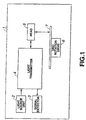
- the optical disc drive 1 includes a light source unit 2, signal detector 3, light transmitter 4, head 5 and a disc rotation drive 6.
- a light emitted from the light source unit 2 is guided through the light transmitter 4 to the head 5 for radiation to an optical disc 7 being rotated by the disc rotation drive 6, and a return light from the optical disc 7 is guided by the light transmitter 4 via the head 5 to the signal detector 3 which will thus detect signals carried by the return light.
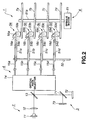
- the above optical disc drive 1 is constructed as shown in further detail in FIG. 2. As shown, the optical disc drive 1 has installed therein four magneto-optical discs including a first one 7a, second one 7b, third one 7c and fourth one 7d as the optical disc. The optic disc drive 1 will write and/or read signals to and/or from a selected one of these first to fourth magneto-optical discs 7a, 7b, 7c and 7d.
- the light source unit 2 includes a light source 11 made of a semiconductor laser for example and a combination lens 12 which converges a light emitted from the light source 11. The light converged by the combination lens 12 will be guided by the light transmitter 4 to the head 5.
- the light transmitter 4 includes a beam splitter 13 which splits an optical path for a light from the light source unit 2 and an optical path for a return light going towards the signal detector 3 from each other, an optical path selector 14, a plurality of polarization maintaining optical fibers, first to fourth, 15a, 15b, 15c and 15d, corresponding to the first to fourth magneto-optical discs 7a, 7b. 7c and 7d, respectively, and a plurality of phase difference generators, first to fourth, 16a, 16b, 16c and 16d, also corresponding to the first to fourth magneto-optical discs 7a, 7b, 7c and 7d, respectively.
- the optical path selector 14 includes a rotator 21 which is rotated by a stepping motor or the like (not shown) with a center axis of rotation CL thereof being aligned with the optical path of the light having transmitted through the beam splitter 13.
- the rotator 21 has installed thereon a first mirror 22 disposed on the center axis of rotation CL of the rotator 21 and tilted 45 deg. with respect to the center axis of rotation CL and a second mirror 23 disposed parallel to the first mirror 22 and in a position off the center axis of rotation CL.
- the second mirror 23 installed in a position off the center axis of rotation CL of the rotator 21 will move delineating a circle when the rotator 21 is rotated. Therefore, the optical path of the light reflected by the second mirror 23 is also changed as the rotator 21 is rotated.
- first to fourth polarization maintaining optical fibers 15a, 15b, 15c and 15d By disposing the first to fourth polarization maintaining optical fibers 15a, 15b, 15c and 15d in such a manner that their one ends will be positioned with a predetermined spacing between them along the moving locus of the second mirror 23 and controlling the rotation of the rotator 21 so that the optical path of the reflected light from the second mirror 23 will be centered coincident with the optical axis of a selected one of the first to fourth polarization maintaining optical fibers 15a, 15b, 15c and 15d, it is possible to make an incidence of the light upon only the selected polarization maintaining optical fiber.
- an optical path is selected for a light from the light source unit 2 by the optical path selector 14 to lead the light for incidence upon a selected one ofthe first to fourth polarization maintaining optical fibers 15a, 15b, 15c and 15d and thus radiate the light to only a one of the magneto-optical discs 7a, 7b, 7c and 7d corresponding to the selected polarization maintaining optical fiber, whereby signals are written to and/or read from the magneto-optical disc.
- the optical path selector 14 reflects a return light from the magneto-optical disc and returned through the selected polarization maintaining optical fiber by the second and first mirrors 23 and 22 in this order towards the beam splitter 13.
- the return light incident upon the beam splitter 13 is reflected by the latter towards the signal detector 3.
- the return light from the magneto-optical disc is returned with the polarization axis thereof rotated under the Kerr effect. Since this optical disc drive 1, since the Kerr effect is utilized to detect signals written in the magneto-optical disc, it is necessary to guide the return light to the signal detector 3 with the Kerr rotation angle being maintained. Since the optical path selector 14 uses the first and second mirrors 22 and 23 to change the optical path from one to another, when a light is reflected by the first and second mirrors 22 and 23, the light will incur a phase difference between field vibration components.
- a dielectric membrane for example, as a reflective layer of the first and second mirrors 22 and 23 in order to multiply the phase difference between field vibration components, produced in the light reflected as in the above by an integer multiple of ⁇ .
- the first to fourth polarization maintaining optical fibers 15a, 15b, 15c and 15d (will generically be referred to as "polarization maintaining optical fiber 15" whenever appropriate hereunder) are adapted to impart a stress in one direction of the core through which a light is guided, thereby causing a difference in refractive index between the direction in which the stress is imparted and a direction perpendicular to the above direction to allow the polarization maintaining optical fiber 15 to show a birefringence.
- the distribution of the refractive index of birefringence can be predicted.
- FIG. 4 schematically illustrates the cross section of a so-called PANDA type polarization maintaining optical fiber having been proposed as an example of the above polarization maintaining optical fiber 15.
- the PANDA type polarization maintaining optical fiber 15 includes a core 31 having a large refractive index covered by a clad 32 whose refractive index is smaller than that of the core 31, and a pari of stress raisers 33a and 33b disposed also in the clad 32 at both sizes of the core 31, respectively, to impart stresses to the core 31.
- This PANDA type polarization maintaining optical fiber 15 is formed as a tube in which the core 31 has an extremely small circular section having a diameter of 5 ⁇ m for example and the clad 32 has a circular section having a diameter of 125 ⁇ m for example.
- the core 31 In the polarization maintaining optical fiber 15, a light incident upon the core 31 is allowed to travels while being totally reflected repeatedly at the boundary between the core 31 and clad 32. At this time, in the PANDA type polarization maintaining optical fiber 15, stresses are imparted by the pair of stress raisers 33a and 33b to the core 31 in a direction from the center of the core 31 to that of the pair of stress raisers 33a and 33b (in the direction of a Y axis in FIG. 4). Therefore, the core 31 will have a birefringence caused by a difference in refractive index between the Y-axial direction and a direc5tion perpendicular to the Y axis (in the direction of an X axis in FIG. 4).
- a linearly polarized light incident in the Y-axial direction or in the X-axial direction perpendicular to the Y axis, to which the stress of the core 31 is imparted, can be transmitted with its polarization being maintained.
- the optical disc drive 1 uses the magneto-optical disc as an optical disc 7, and thus a light going towards the magneto-optical disc will be polarized in one direction while a return light from the magneto-optical disc will be polarized in the other direction, under the Kerr effect.
- the above light beams are made incident upon the polarization maintaining optical fiber 15 in the off-axis manner in this optical disc driver 1, whereby the light traveling through the polarization maintaining optical fiber 15 will incur a phase difference between field vibration components.
- the first to fourth phase difference generators 16a, 16b, 16c and 16d are provided in the optical paths for light beams traveling through the polarization maintaining optical fibers 15, respectively, to cancel a phase difference between field vibration components taking place in a light traveling through the polarization maintaining optical fiber 15 with a phase difference generated by each of the first to fourth phase difference generators 16a, 16b, 16c and 16d or to multiply the phase difference by an integer multiple of ⁇ , thereby suppressing the influence of the birefringence of the polarization maintaining optical fiber 15, and thus the optical disc drive 1 can detected magneto-optical signals properly.
- phase difference generator 16 (will generically be referred to as "phase difference generator 16" wherever appropriate hereunder) are provided to positively raise a phase difference in a transmitted light, thereby canceling a phase difference between field vibration components, raised in a light traveling through the polarization maintaining optical fiber 15 or multiplying the phase difference by an integer multiple of ⁇ .
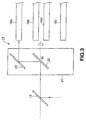
- phase difference generator 16 An example of such a phase difference generator 16 is schematically illustrated in FIG. 5.
- the phase difference generator 16 is called “Babinet compensator” being a combination of a pair of wedge-shaped birefringent crystals 41 and 42 whose crystal axes are perpendicular to each other.
- the birefringent crystals 41 and 42 are made of a uniaxial birefringent material such as calcite, quartz or the like.
- the uniaxial birefringent material has two different refractive indices one in a direction along the crystal axis and the other in a direction perpendicular to the crystal-axial direction.
- the uniaxial birefringent crystal is formed to be a wedge.
- the birefringent crystals 41 and 42 in pair thus formed are joined with their slat faces laid to butt on each other to form the phase difference generator 16.
- the birefringent crystals 41 and 42 in pair are moved in the direction of arrow A in FIG. 5 along their butting surfaces to properly change the thickness of the birefringent crystals 41 and 42 at a part of the phase difference generator 16 through a light is transmitted to set a phase difference raised in the light transmitted through the phase difference generator 16 to an arbitrary value.
- ⁇ 2 -2 ⁇ d 2 (
- phase difference generator 16 is disposed in the optical path for the light traveling through the polarization maintaining optical fiber 15 to have the light traveling through the polarization maintaining optical fiber 15 to pass through the phase difference generator 16 in order to generate a phase difference in the light, thereby canceling a phase difference raised in the light traveling through the polarization maintaining optical fiber 15 by the generated phase difference or multiplying the phase difference raised in the light (a phase difference raised in the light traveling through the polarization maintaining optical fiber 15 + phase difference raised in. the light passing through the phase difference generator 16) by an integer multiple of ⁇ .
- phase difference generator 16 formed from a combination of the wedge-shaped birefringent crystals 41 and 42 in pair, has been described.
- the phase difference generator 16 is not limited to the above mentioned one by may be made of a one selected from a wide variety of birefringent materials.
- the phase difference generator 16 may be made of a single birefringent crystal formed in the form of a wedge from a uniaxial birefringent material. In this case, by changing the incident position of a light upon the birefringent crystal properly, it is possible to set a phase difference raised in the light transmitted through the birefringent crystal to an arbitrary value. In this case, however, since the direction in which the light transmitted through the birefringent crystal travels will vary, it is necessary to adjust the optical system.
- the four phase difference generators 16 (first to fourth ones 16a, 16b, 16c ad 16d) are provided correspondingly to the first to fourth polarization maintaining optical fibers 15a, 15b, 15c and 15d, respectively.
- the first to fourth phase difference generators 16a, 16b, 16c ad 16d are mounted on the four heads 5 (first to fourth ones 5a, 5b, 5c and 5d) provided correspondingly to the first to fourth magneto-optical discs 7a, 7b, 7c and 7d, respectively.
- the first to fourth heads 5a, 5b, 5c and 5d are provided with support arms 51a, 51b, 51c and 51d supported at the base ends thereof and provided for the free ends thereof to face top sides of the first to fourth magneto-optical discs 7a, 7b, 7c and 7d, respectively.
- the support arms 51a, 51b, 51c and 51d are provided each at the base end thereof with a turning drive such as a voice coil motor or the like, respectively.
- a turning drive such as a voice coil motor or the like.
- Each of the support arms 51a, 51b, 51c and 51d is turned about a spindle 52 by the turning drive.
- the support arms 51a, 51b, 51c and 51d have floating slides 53a, 53b, 53c and 53d, respectively, fixed at the free ends thereof and at the sides of the latter opposite to the first to fourth magneto-optical discs 7a, 7b, 7c and 7d, respectively.
- Each of the floating sliders 53a, 53b, 53c and 53d is applied with an air flow generated when a corresponding one of the first to fourth magneto-optical discs 7a, 7b, 7c and 7d is rotated, and thus is floated a predetermined amount above the magneto-optical disc.
- each of the support arms 51a, 51b, 51c and 51d is turned by the turning drive and a corresponding one of the magneto-optical discs 7a, 7b, 7c and 7d is driven to spin, a corresponding one of these floating slides 53a, 53b, 53c and 53d is scanned over the corresponding magneto-optical disc.
- the floating sliders 53a, 53b, 53c and 53d incorporate objective lenses 54a, 54b, 54c and 54d, respectively.
- Each of the objective lenses 54a, 54b, 54c and 54d condenses a light emitted from the light source unit 2 and guide to a corresponding one of the first to fourth heads 5a, 5b, 5c and 5d through the light transmitter 4, and radiates the light to a corresponding one of the first to fourth magneto-optical discs 7a, 7b, 7c and 7d.
- the light condensed through the corresponding one of the objective lenses 54a, 54b, 54c and 54d and radiated to the corresponding one of the first to fourth magneto-optical discs 7a, 7b, 7c and 7d forms a light spot on the signal recording surface of the magneto-optical disc. Signals will be written to a part of the magneto-optical disc where the light spot is defined, and also signals be read from such a part of the magneto-optical disc.
- the floating. sliders 53a, 53b, 53c and 53d incorporate magnetic coils (not shown) along with the objective lenses 54a, 54b, 54c and 54d, respectively.
- a magnetic field is applied to a part of each of the first to fourth magneto-optical discs 7a, 7b, 7c and 7d on which a light spot is defined to write signals to that part of the magneto-optical disc.
- the support arms 51a, 51b, 51c and 51d have provided at the free ends thereof optical path bending mirrors 55a, 55b, 55c and 55d, respectively, which reflect a light having been guided by the light transmitter 4 to the free end of each of the support arms 51a, 51b, 51c and 51d for incidence upon a corresponding one of the first to fourth objective lenses 54a, 54b, 54c and 54d, and also reflect a return light from a corresponding one of the first to fourth magneto-optical discs 7a, 7b, 7c and 7d towards the light transmitter 4.
- the first to fourth magneto-optical discs 7a, 7b, 7c and 7d are mounted on the disc rotation drive 6.
- This disc rotation drive 6 includes a spindle motor 61 and a motor control circuit (not shown) which controls the operation of the spindle motor 61.
- the first to fourth magneto-optical discs 7a, 7b, 7c and 7d are installed together to a spindle 61 a of the spindle motor 61, and thus they are driven by the spindle motor 61 to rotate together at a constant angular velocity.
- a light emitted from the light source unit 2 will be transmitted to a selected one of the first to fourth heads 5a, 5b, 5c and 5d via the light transmitter 4.
- the light is condensed by the objective lens installed to the selected head will be radiated to a one of the first to fourth magneto-optical discs 7a, 7b, 7c and 7d being rotated together by the spindle motor 61, corresponding to the selected head.
- a return light from that magneto-optical disc will be transmitted by the light transmitter 4 to the signal detector 3.
- the signal detector 3 includes a polarization beam splitter 71 to polarize and split a return light reflected from a magneto-optical disc and transmitted by the light transmitter 4, a first photodetector 72 to receive one polarized light component from the polarization beam splitter 71 and convert it to an electricity, and a second photodetector 73 to receive the other polarized light component from the polarization beam splitter 71 and convert it to an electricity.
- the signal detector 3 Based on the detection signal resulted from the light received and photoelectrically converted by the first photodetector 72 and that resulted from the light received and photoelectrically converted by the second photodetector 73, the signal detector 3 will produce a read signal from the magneto-optical disc, servo control signals such as a tracking error signal, focusing error signal, position information, etc. Note that a magneto-optical signal being the read signal from the magneto-optical disc is acquired from a difference between the detection signal from the first photodetector 72 and that from the second photodetector 73.
- the operations effected by the optical disc drive 1 for reading signals recorded in each of the first to fourth magneto-optical discs 7a, 7b, 7c and 7d will be described herebelow. Note that the operations for reading signals recorded in the first one (7a) of the first to fourth magneto-optical discs 7a, 7b, 7c and 7d will be described by way of example and those for reading signals from each of the other magneto-optical discs 7b, 7c and 7d will be done similarly.
- the spindle motor 61 For reading signals recorded in the first magneto-optical disc 7a, first the first to fourth magneto-disc discs 7a, 7b, 7c and 7d are rotated together by the spindle motor 61. Then position information indicative of the present position of the first head 5a is detected, the turning drive such as a voice coil motor or the like is put into operation based on the position information to turn the support arm 51a, and the floating slider 53a is taken to a predetermined position on the first magneto-optical disc 7a.
- the turning drive such as a voice coil motor or the like
- a reading light is emitted from the light source 11.
- the light emitted from the light source 11 is condensed by the combination lens 12, transmitted through the beam splitter 13 and incident upon the optical path selector 14.
- the light incident upon the optical path selector 14 is reflected by the first mirror 22, and then reflected by the second mirror 23 for incidence upon the first polarization maintaining optical fiber 15a selected from the first to fourth polarization maintaining optical fibers 15a, 15b, 15c and 15d.
- the incident light upon the first polarization maintaining optical fiber 15a travels through the core 31 while being repeatedly reflected at the boundary between the core 31 and clad 32 of the first polarization maintaining optical fiber 15a and thus transmitted to the free end of the support arm 51a. At this time, the light transmitted by the first polarization maintaining optical fiber 15a will incur a phase difference between field vibration components due to the birefringence of the first polarization maintaining optical fiber 15a.
- the light going out of the first polarization maintaining optical fiber 15a passes through the first phase difference generator 16a.
- the light having traveled through the first polarization maintaining optical fiber 15a and passing through the first phase difference generator 16a will have a phase difference which will cancel the phase difference between field vibration components raised due to the birefringence of the first polarization maintaining optical fiber 15a or multiply the phase difference by an integer multiple of ⁇ .
- the light having passed through the first phase difference generator 16a is reflected by the optical path bending mirror 55a for incidence upon the objective lens 54a incorporated in the floating slider 53a of the first head 5a.
- the floating slider 53a is applied with air flow generated by the first magneto-optical disc 7a being rotated and floated a predetermined amount over the first magneto-optical disc 7a.
- the light incident upon the objective lens 54a is condensed by the latter for radiation as a linearly polarized light to a predetermined position on the first magneto-optical disc 7a.
- a light spot is formed to a predetermined position on the first magneto-optical disc 7a.
- the light radiated as the linearly polarized light to the predetermined position on the first magneto-optical disc 7a has the polarization axis thereof rotated under the influence of a magnetic field (recording signal) applied to that position.
- a return light from the first magneto-optical disc 7a is incident again with the polarization axis rotated upon the first phase difference generator 16a via the objective lens 45a and optical path bending mirror 55a.
- the return light having passed through the first phase difference generator 16a is transmitted by the first polarization maintaining optical fiber 15a.
- a phase difference raised between field vibration components when the return light traveling through the first polarization maintaining optical fiber 15a will be canceled by a phase difference raised when the return light passes through the first phase difference generator 16a or multiplied by an integer multiple of ⁇ .
- the return light transmitted by the first polarization maintaining optical fiber 15a reaches the beam splitter 13 via the optical path selector 14 and is reflected by the beam splitter 13 towards the polarization beam splitter 71.
- the return light having thus reached the polarization beam splitter 71 which will polarize and split the return light. That is, one polarized component of the return light having reached the polarization beam splitter 71 is transmitted through the polarization beam splitter 71 while the other polarized component is reflected by the polarization beam splitter 71.
- the one polarized light component having transmitted through the polarization beam splitter 71 is received or detected by the first photodetector 72. Also, the other polarized light component reflected by the polarization beam splitter 71 is received by the second photodetector 73. The return light received by these first and second photodetectors 72 and 73 is photoelectrically converted and detected as a detection signal by the first and second photodetectors 72 and 73.
- a read signal (magneto-optical signal) from the first magneto-optical disc 7a, servo control signals, etc. are produced.
- the light emitted from the light source 11 and return light from the magneto-optical discs 7a, 7b, 7c and 7d are transmitted by the polarization maintaining optical fiber 15 as having been described in the foregoing.
- a phase difference between field vibration components, raised in the light beams traveling through the polarization maintaining optical fiber 15 due to the birefringence of the latter, is canceled by a phase difference generated by the phase difference generator 16, or multiplied by an integer multiple of ⁇ .
- FIG. 6 shows a multi-mode dispersion which causes pulse signals to incur a delay distortion in the polarization maintaining optical fiber 15.
- the vertical axis indicates a normalized frequency V and the horizontal axis shows a normalized propagation coefficient ⁇ /k.
- FIG. 7 there is illustrated in the form of a a sectional view the core 31 and its neighborhood, taken along the length (Z-axial direction) of the polarization maintaining optical fiber 15 shown in FIG. 4, perpendicular to the X and Y axes in FIG. 4.
- the relation between the propagation coefficient ⁇ and number of waves k will be explained herebelow with reference to FIG. 7.
- the normalized propagation coefficient ⁇ /k is the refractive index n clad of the clad 32.
- the light when the normalized propagation coefficient ⁇ /k is nearer to the refractive index n core of the core 31, the light can be bound in the core 31 for propagation through the polarization maintaining optical fiber 15, and when the normalized propagation coefficient ⁇ /k is nearer to the refractive index n clad of the clad 32, the light cannot be bound in the core 31 and can hardly be propagated through the polarization maintaining optical fiber 15.
- the bound mode for the light propagated through the core 31 having no birefringence is degenerated, but if there exists a birefringence, the degeneracy will be canceled and the mode will be divided into two bound modes HE11, x and HE11, y as shown in FIG. 6.
- the term "degeneracy” means a reduced freedom of the bound mode.
- only the HE11, x and HE11, y modes permit to define a range of the normalized frequency V which can be propagated. This range is called "polarization maintenance area" in which the polarization maintaining optical fiber 15 can work well. Therefore, when the normalized frequency V has a value in the above range, the core 31 of the polarization maintaining optical fiber 15 will have a birefringence.
- the polarization maintaining optical fiber 15 When the. normalized frequency V takes a larger value than the polarization maintenance area, the propagation is made in multiple modes, resulting in a multi-mode dispersion with which magneto-optical signal light can hardly be propagated.
- the wavelength of the normalized frequency V which will lead to the multi-mode dispersion is generally called "cutoff wavelength".
- the polarization maintaining optical fiber 15 having been described in the foregoing is commercially available.
- the difference in birefringent index is on the order of 6 ⁇ 10 -4 and the cutoff wavelength is about 600 nm.
- the direction of refractive index distribution of the polarization maintaining optical fiber 15 can be known at a stage where the polarization maintaining optical fiber 15 is delivered from its manufacturer.
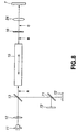
- FIG. 8 is a schematic diagram of the optical path along which a light going towards the magneto-optical disc 7 travels, including the polarization maintaining optical fiber 15, and FIGS. 9 to 11 schematically illustrate the polarized state of the light going towards the magneto-optical disc 7 as viewed from the traveling direction of the light.
- FIGS. 9 to 11 schematically illustrate the polarized state of the light going towards the magneto-optical disc 7 as viewed from the traveling direction of the light.
- each of the pair of mirrors 22 and 23 of the optical path selector 14 should preferably have a dielectric membrane formed on the reflective surface thereof as having previously been described and the reflection-caused change of the phase difference between field vibration components should be set to an integer multiple of ⁇ .
- a light emitted from the light source 11 and transmitted through the combination lens 12 and beam splitter 13 is a linearly polarized one. It is incident upon the polarization maintaining optical fiber 15 with the polarization axis inclined an angle of 45 ° with respect to the X axis of the polarization maintaining optical fiber 15 as shown in FIG. 9. Note that FIG. 9 shows the polarized state of the light at a position indicated with an arrow A in FIG. 8 as viewed from the traveling direction of the light.
- the light will be propagated through the polarization maintaining optical fiber 15. During this propagation, the light will be elliptically or circularly polarized under the influence of a phase difference raised due to the birefringence of the polarization maintaining optical fiber 15.
- FIG. 10 shows the polarized state of the light at a position indicated with an arrow B in FIG. 8 as viewed from the traveling direction of the light.
- the retardation of the phase difference generator 16 (phase retardation of field vibration components of the light) should be set to such a value as cancels a phase difference raised due to the birefringence of the polarization maintaining optical fiber 15 or as multiplies the phase difference. by an integer multiple of ⁇ .
- phase difference between field vibration components depends upon the length and birefringent index, and will vary when the length and birefringent index of the polarization maintaining optical fiber 15 vary. Therefore, to absorb the variation of the phase difference between field vibration components, the retardation of the phase difference generator 16 has to be adjusted.
- the retardation of the phase difference generator 16 can easily be adjusted for example by changing the thicknesses d 1 and d 2 of parts of the birefringent crystals 41 and 42 through which the light is transmitted as in the above.
- phase difference generators 16a, 16b, 16c and 16d are provided correspondingly to the plurality of polarization maintaining optical fibers 15a, 15b, 15c and 15d, respectively, as having previously been described, the retardation of each of the phase difference generators 16a, 16b, 16c and 16d should be adjusted in advance, whereby it is not necessary to readjust it after that.
- phase difference generator 16 The light incident upon the phase difference generator 16 is passed through the latter to generate a phase difference which will cancel a phase difference raised due to the birefringence of the polarization maintaining optical fiber 15 or multiply the birefringence-caused phase difference by an integer multiple of ⁇ .
- the light will be rendered linearly polarized as shown in FIG. 11, and go out of the phase difference generator 16.
- FIG. 11 shows the polarized state of the light at a position indicated with an arrow C in FIG. 8 as viewed from the traveling direction of the light.
- the light rendered linearly polarized owing to the transmission through the phase difference generator 16 is incident upon the objective lens 54 which will radiate it to a predetermined recording position on the magneto-optical disc 7.
- a light spot will be defined in the predetermined recording position on the magneto-optical disc 7.
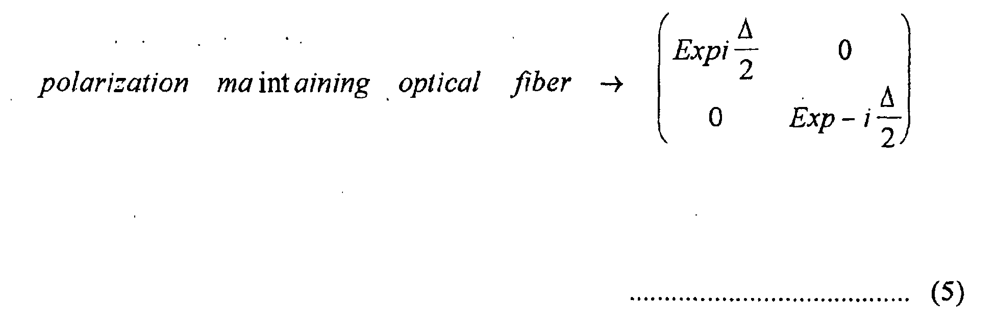
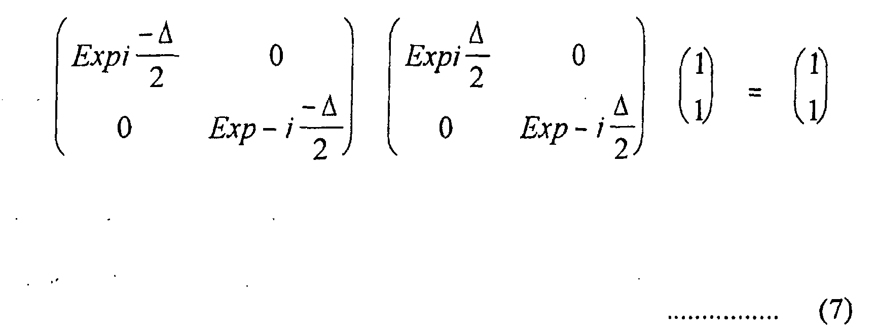
- the Jones matrix is a notation of a polarized state of light, and the polarized state of the light emitted from the light source 11 is given by the following expression (4):
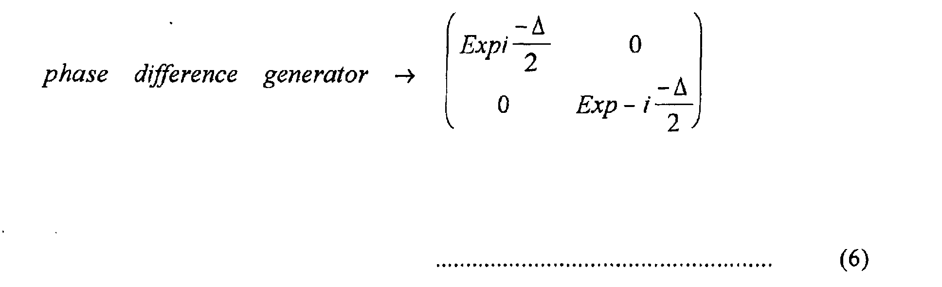
- phase difference generator 16 disposed for the crystal axes X and Y thereof to coincide with the advanced and retarded axes of the polarization maintaining optical fiber 15 is given by the following expression (6): where i is an imaginary number and ⁇ is a phase difference raised due to the birefringence of the polarization maintaining optical fiber.
- the polarized state of the light emitted from the light source 11 is stored. That is, the linearly polarized light emitted from the light source 11 is transmitted through the polarization maintaining optical fiber 15, and then passed through the phase difference generator 16. Thus, the polarized state of the light will be maintained and radiated to the magneto-optical disc 7 while maintaining its polarized state. Note that for recording magneto-optical signals, the temperature of a light spot defined on the magneto-optical disc 7 is elevated to above the Curie point. Also, for reading magneto-optical signals, the rotation of the plane of polarization under the Kerr effect, that is, the Kerr rotation, is detected from the reflected light from the magneto-optical disc 7.
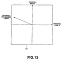
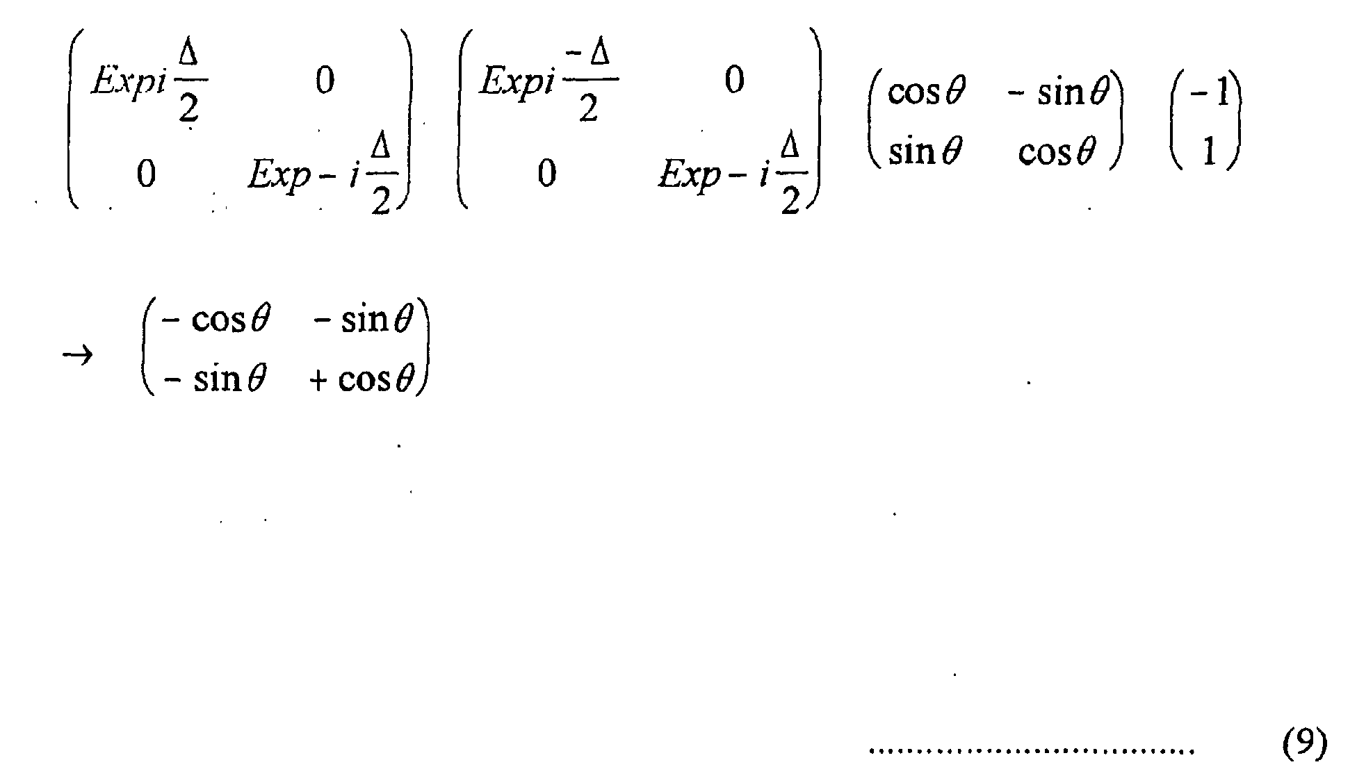
- FIG. 13 shows the polarized state of the return light at a position indicated with the arrow C in FIG. 8 as viewed from the traveling direction of the return light.
- the return light incident upon the phase difference generator 16 is elliptically or circularly polarized under the influence of the phase difference raised when the return light is passed through the phase difference generator 16.
- the return light passed through the phase difference generator 16 is incident again upon the polarization maintaining optical fiber 15 while being in the elliptically or circularly polarized state as shown in FIG. 14.
- FIG. 14 shows the polarized state of the return light at the position indicated with the arrow B in FIG. 8 as viewed from the traveling direction of the return light.
- FIG. 15 shows the polarized state of the return light at the position indicated with the arrow A in FIG. 8 as viewed from the traveling direction of the return light.
- the return light going out of the polarization maintaining optical fiber 15 is reflected by the beam splitter 13, then polarized and split by the polarization beam splitter 71, and received by the first and second photodetectors 72 and 73.
- magneto-optical signals will be detected.
- the above expression (11) means the polarization axis of the linearly polarized light emitted from the light source 11, rotated by - ⁇ . That is, it is known that the Kerr rotation angle of the return light is maintained.
- the optical disc drive 1 is adapted such that a phase difference between field vibration components, raised when a light emitted from the light source 11 is propagated through the polarization maintaining optical fiber 15, and a one raised when a return light from a magneto-optical disc is propagated through the polarization maintaining optical fiber 15, are canceled by a phase difference produced by the phase difference generator 16 or multiplied by an integer multiple of ⁇ .
- this optical disc drive 1 a linearly polarized light emitted from the light source 11 is radiated to the magneto-optical disc 7 while being maintained linearly polarized, and a linearly polarized return light reflected by the magneto-optical disc 7 and whose polarization axis is rotated by a Kerr rotation angle is incident upon the first and second photodetectors 72 and 73 as a linearly polarized light maintaining the Kerr rotation angle, to properly detect magneto-optical signals from the magneto-optical disc 7.
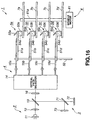
- the optical disc drive 1 in which the four phase difference generators 16a, 16b, 16c and 16d are provided correspondingly to the four polarization maintaining optical fibers 15a, 15b, 15c and 15d, respectively but the optical disc drive 1 may be adapted such that a phase difference between field vibration components, raised in a light propagated through each of the polarization maintaining optical fibers 15a, 15b, 15c and 15d, can be canceled or multiplied by an integer multiple of ⁇ by the use of a single phase difference generator 16 as shown in FIG. 16.
- the phase difference generator 16 is to be disposed between the beam splitter 13 and optical path selector 14.
- phase difference generator 16 By canceling, or multiplying by an integer multiple of ⁇ , a phase difference between field vibration components, raised in a light propagated through each of the polarization maintaining optical fibers 15a, 15b, 15c and 15d, by the user of the phase difference generator 16, it will be possible to manufacture the optical disc drive 1 with a reduced number of parts and less costs. In this case, however, if there exists a variation in length and birefringent index among the polarization maintaining optical fibers 15a, 15b, 15c and 15d, it is necessary to adjust the retardation of the aforementioned phase difference generator 16 for each of the polarization maintaining optical fibers 15a, 15b, 15c and 15d.
- the optical disc drive 1 in which the four magneto-optical discs 7a, 7b, 7c and 7d are installed and signals are written and/or read to and/or from a selected one of the four magneto-optical discs 7a, 7b, 7c and 7d.
- the optical disc drive 1 may be adapted to write and/or read signals to and/or from a single magneto-optical disc 7. In this case, the optical path selected 14 becomes unnecessary and there will be provided only a single polarization maintaining optical fiber 15, phase difference generator 16 and a single head 5 each.
- the optical disc drive 1 in which the magneto-optical discs 7a, 7b, 7c and 7d are installed on the spindle 61a of the spindle motor 61.
- the present invention is not limited to the above embodiment but can be applied to an optical disc drive in which the optical disc 7 is loadable in and removable from the drive unit, or a so-called disc-removable type optical disc drive.
- the present invention has been described in the foregoing concerning the optical disc drive 1 in which the magneto-optical discs are used as optical discs 7.
- the type of optical discs used in the optical disc drive 1 is not limited to the magneto-optical type but a pit-pattern disc represented by CD (compact disc) and phase-change disc represented by DVD-RAM (digital video disc-random access memory) may be used as the optical disc 7.
- a pit-pattern disc or phase-change disc is used as the optical disc 7 in the aforementioned optical disc drive 1, read signals can be obtained without any trouble based on a change in amount of the return light from the optical disc 7.
- the plurality of optical discs 7 may include ones of the same type or difference types.
- the optical disc drive according to the present invention a phase difference between field vibration components, raised in a light traveling through the polarization maintaining optical fiber is canceled by a phase difference produced by the phase difference generator or multiplied by an integer multiple of ⁇ , thereby permitting to properly detect magneto-optical signals. Therefore, the optical disc drive according to the present invention is compatible with all types of optical discs including a magneto-optical disc.
Landscapes
- Physics & Mathematics (AREA)
- Optics & Photonics (AREA)
- Optical Head (AREA)
Abstract
Description




Claims (9)
- An optical disc drive comprising:means for rotating an optical disc;a light source to emit a light used for write and/or read of signals to and/or the optical disc;a head having installed therein an objective lens which converges the light emitted from the light source and being scanned over the optical disc being rotated by the rotating means to radiate the light converged by the objective lens to the optical disc;means for receiving a return light being a part of the light radiated from the head to the optical disc and which is reflected from the optical disc and detecting signals from the return light; andmeans for transmitting the light emitted from the light source to the head and the return light from the optical disc to the signal detecting means;the light transmitting means including a polarization maintaining optical fiber and phase difference generating means to cancel out a phase difference between electric field vibration components generated when the light going towards the head or the return light going towards the signal detecting means is guided through the polarization maintaining optical fiber by the phase difference generated by the phase difference generating means or multiply the phase difference by an integer multiple of π.
- The optical disc drive according to claim 1, wherein the phase difference generating means is a combination of a pair of wedge-shaped birefringent crystals whose crystal axes are perpendicular to each other.
- The optical disc drive according to claim 1, wherein the optical disc is a magneto-optical disc.
- An optical disc drive comprising:means for rotating a plurality of optical discs together;a light source which emits a light for use to write and/or read signals to the plurality of optical discs;a plurality of heads provided correspondingly to the plurality of optical discs, each of which has installed thereon an objective lens to converge a light emitted from the light source and is canned over an appropriate optical disc being rotated by the disc rotating means to radiate the light converged by the objective lens to the optical disc;means for receiving a return light being a part of the light radiated to the optical disc from a corresponding one of the plurality of heads to detect signals carried by the light; andmeans for transmitting the light emitted from the light source to each of the plurality of heads and the return light from the optical disc to the signal detecting means;the light transmitting means includes a plurality of polarization maintaining optical fibers corresponding to the plurality of optical discs, optical path selecting means for making a selection between an optical path for the light emitted from the light source and a one for the return light going towards the signal detecting means, and means for generating a phase difference, a phase difference between field vibration components, having taken place when the light going towards the head or the return light going towards the signal detecting means goes through a one of the polarization maintaining optical fibers, selected by the optical path selecting means, being canceled out by a phase difference generated by the phase difference generating means or being multiplied by an integer multiple of π.
- The optical disc drive according to claim 4, wherein a phase difference between field vibration components, raised in the light going towards the head or the return light going towards the signal detecting means when the path for the light or return light is changed from one to another by the optical path selecting means, is multiplied by an integer multiple of π.
- The optical disc drive according to claim 4, wherein the phase difference generating means is a combination of a pair of wedge-shaped birefringent crystals whose crystal axes are perpendicular to each other,
- The optical disc drive according to claim 4, wherein the phase difference generating means are installed on the plurality of heads, respectively.
- The optical disc drive according to claim 4, where in the phase difference generating means is disposed between the optical path selecting means and the light source and signal detecting means.
- The optical disc drive according to claim 4, wherein at least one of the plurality of optical discs is a magneto-optical disc.
Applications Claiming Priority (3)
| Application Number | Priority Date | Filing Date | Title |
|---|---|---|---|
| JP2000048982A JP2001236682A (en) | 2000-02-21 | 2000-02-21 | Optical disk drive |
| JP2000048982 | 2000-02-21 | ||
| PCT/JP2001/001257 WO2001061691A1 (en) | 2000-02-21 | 2001-02-21 | Optical disk device |
Publications (2)
| Publication Number | Publication Date |
|---|---|
| EP1172809A1 true EP1172809A1 (en) | 2002-01-16 |
| EP1172809A4 EP1172809A4 (en) | 2005-01-12 |
Family
ID=18570982
Family Applications (1)
| Application Number | Title | Priority Date | Filing Date |
|---|---|---|---|
| EP01906172A Withdrawn EP1172809A4 (en) | 2000-02-21 | 2001-02-21 | OPTICAL DISC READER |
Country Status (6)
| Country | Link |
|---|---|
| US (1) | US6700855B2 (en) |
| EP (1) | EP1172809A4 (en) |
| JP (1) | JP2001236682A (en) |
| KR (1) | KR100750625B1 (en) |
| CN (1) | CN1172302C (en) |
| WO (1) | WO2001061691A1 (en) |
Families Citing this family (6)
| Publication number | Priority date | Publication date | Assignee | Title |
|---|---|---|---|---|
| JP2004325859A (en) * | 2003-04-25 | 2004-11-18 | Hitachi Printing Solutions Ltd | Optical recorder |
| EP1585119A1 (en) * | 2004-04-06 | 2005-10-12 | Deutsche Thomson-Brandt Gmbh | Device for reading and /or writing optical recording media |
| TWI256633B (en) * | 2004-08-20 | 2006-06-11 | Asustek Comp Inc | Optical component set used in pick up head |
| US7400448B2 (en) * | 2004-11-19 | 2008-07-15 | Optical Physics Company | Birefringent spectral filter |
| US7557820B2 (en) * | 2005-03-16 | 2009-07-07 | Kabushiki Kaisha Toshiba | Optical multi-beam scanning device and image forming apparatus |
| JP2008130106A (en) * | 2006-11-16 | 2008-06-05 | Hitachi Ltd | Thermally assisted magnetic recording head support mechanism |
Family Cites Families (18)
| Publication number | Priority date | Publication date | Assignee | Title |
|---|---|---|---|---|
| JPS5956236A (en) | 1982-09-22 | 1984-03-31 | Canon Inc | optical head |
| JPS61118121A (en) | 1984-11-12 | 1986-06-05 | Mitsubishi Heavy Ind Ltd | Stirrer |
| JPS61118121U (en) * | 1984-12-28 | 1986-07-25 | ||
| JPS62259239A (en) | 1986-05-06 | 1987-11-11 | Hitachi Ltd | Laminated optical disk device |
| JPH07118105B2 (en) * | 1989-06-02 | 1995-12-18 | 日立電線株式会社 | Optical fiber type magneto-optical head |
| US5152597A (en) * | 1990-12-03 | 1992-10-06 | Eastman Kodak Company | Magneto-optic readout using a polarization-preserving optical fiber |
| US5218582A (en) * | 1990-12-03 | 1993-06-08 | Eastman Kodak Company | Magneto-optic readout using a polarization-preserving optical guide |
| JP3412840B2 (en) | 1992-07-17 | 2003-06-03 | 科学技術振興事業団 | Ultra-high resolution writing / reading method and apparatus for optical recording medium |
| JPH07128073A (en) | 1993-11-09 | 1995-05-19 | Japan Aviation Electron Ind Ltd | Fiber optic gyro |
| US5446813A (en) * | 1994-08-08 | 1995-08-29 | Industrial Technology Research Institute | Optical isolator |
| US6034938A (en) * | 1996-07-30 | 2000-03-07 | Seagate Technology, Inc. | Data storage system having an optical processing flying head |
| US5850375A (en) * | 1996-07-30 | 1998-12-15 | Seagate Technology, Inc. | System and method using optical fibers in a data storage and retrieval system |
| JPH11162033A (en) * | 1997-11-28 | 1999-06-18 | Comets:Kk | Magneto-optical recording / reproducing device |
| JPH11162933A (en) | 1997-12-02 | 1999-06-18 | Fujitsu Ltd | Method for manufacturing semiconductor device |
| JPH11219537A (en) | 1998-02-02 | 1999-08-10 | Olympus Optical Co Ltd | Optical pickup |
| US6298027B1 (en) * | 1998-03-30 | 2001-10-02 | Seagate Technology Llc | Low-birefringence optical fiber for use in an optical data storage system |
| US6587421B1 (en) * | 1998-03-30 | 2003-07-01 | Seagate Technology Llc | Refractive index matching means coupled to an optical fiber for eliminating spurious light |
| JP2000067458A (en) * | 1998-08-24 | 2000-03-03 | Sony Corp | Optical disk drive |
-
2000
- 2000-02-21 JP JP2000048982A patent/JP2001236682A/en not_active Withdrawn
-
2001
- 2001-02-21 EP EP01906172A patent/EP1172809A4/en not_active Withdrawn
- 2001-02-21 US US09/958,716 patent/US6700855B2/en not_active Expired - Fee Related
- 2001-02-21 KR KR1020017013240A patent/KR100750625B1/en not_active Expired - Fee Related
- 2001-02-21 CN CNB018002617A patent/CN1172302C/en not_active Expired - Fee Related
- 2001-02-21 WO PCT/JP2001/001257 patent/WO2001061691A1/en not_active Ceased
Also Published As
| Publication number | Publication date |
|---|---|
| KR20010112437A (en) | 2001-12-20 |
| KR100750625B1 (en) | 2007-08-20 |
| CN1172302C (en) | 2004-10-20 |
| EP1172809A4 (en) | 2005-01-12 |
| JP2001236682A (en) | 2001-08-31 |
| WO2001061691A1 (en) | 2001-08-23 |
| US20020136149A1 (en) | 2002-09-26 |
| CN1363089A (en) | 2002-08-07 |
| US6700855B2 (en) | 2004-03-02 |
Similar Documents
| Publication | Publication Date | Title |
|---|---|---|
| US5850375A (en) | System and method using optical fibers in a data storage and retrieval system | |
| EP0777222B1 (en) | Optical pickup having two objective lenses | |
| JP3478404B2 (en) | Optical read head | |
| JP2000501546A (en) | Magneto-optical recording system using near-field optics | |
| US5745265A (en) | Optical element utilized for optical storage unit and optical device including the optical element | |
| JP2003532963A (en) | Optical data storage system with means for reducing noise from spurious reflections | |
| JPS63188844A (en) | Pickup for magneto-optical recording medium | |
| EP1811511A2 (en) | Optical recording/reprducing apparatus, optical pickup, and tracking error detecting method | |
| US6700855B2 (en) | Optical disk device | |
| US4977552A (en) | Split type optical pick-up device with a tracking error detector on the moving part | |
| JP2008243282A (en) | Optical information recording / reproducing device | |
| US6657942B2 (en) | Optical recording and reproducing apparatus having floating swing arm and optical disk for use therewith | |
| JP2522858B2 (en) | Optical recording device | |
| JP2003522362A (en) | Optical information recording system using polarization maintaining optical fiber | |
| US6349082B1 (en) | Optical disc apparatus | |
| US5805750A (en) | Optical wavefront correction for variable groove depth grating waveguide couplers | |
| JPH0572657B2 (en) | ||
| EP1450357B1 (en) | Optical pickup and information reproducing apparatus having the same | |
| JP3822406B2 (en) | Optical head device | |
| JP3505282B2 (en) | Optical head device and information processing device | |
| US20040228257A1 (en) | Optical pickup | |
| JPH0423233A (en) | Method and device for controlling light spot | |
| JP2843154B2 (en) | Optical head | |
| JP2813255B2 (en) | Optical tape memory device, signal detection method for optical tape memory device, and optical tape cassette | |
| JPH10116434A (en) | Optical pickup device |
Legal Events
| Date | Code | Title | Description |
|---|---|---|---|
| PUAI | Public reference made under article 153(3) epc to a published international application that has entered the european phase |
Free format text: ORIGINAL CODE: 0009012 |
|
| 17P | Request for examination filed |
Effective date: 20011017 |
|
| AK | Designated contracting states |
Kind code of ref document: A1 Designated state(s): AT BE CH CY DE DK ES FI FR GB GR IE IT LI LU MC NL PT SE TR |
|
| AX | Request for extension of the european patent |
Free format text: AL;LT;LV;MK;RO;SI |
|
| RBV | Designated contracting states (corrected) |
Designated state(s): DE FR GB |
|
| A4 | Supplementary search report drawn up and despatched |
Effective date: 20041125 |
|
| 17Q | First examination report despatched |
Effective date: 20050307 |
|
| STAA | Information on the status of an ep patent application or granted ep patent |
Free format text: STATUS: THE APPLICATION IS DEEMED TO BE WITHDRAWN |
|
| 18D | Application deemed to be withdrawn |
Effective date: 20060808 |