EP1172652A1 - Measuring system - Google Patents
Measuring system Download PDFInfo
- Publication number
- EP1172652A1 EP1172652A1 EP01904530A EP01904530A EP1172652A1 EP 1172652 A1 EP1172652 A1 EP 1172652A1 EP 01904530 A EP01904530 A EP 01904530A EP 01904530 A EP01904530 A EP 01904530A EP 1172652 A1 EP1172652 A1 EP 1172652A1
- Authority
- EP
- European Patent Office
- Prior art keywords
- sensor
- guide
- measuring device
- measuring system
- measuring
- Prior art date
- Legal status (The legal status is an assumption and is not a legal conclusion. Google has not performed a legal analysis and makes no representation as to the accuracy of the status listed.)
- Granted
Links
Images



Classifications
-
- G—PHYSICS
- G01—MEASURING; TESTING
- G01N—INVESTIGATING OR ANALYSING MATERIALS BY DETERMINING THEIR CHEMICAL OR PHYSICAL PROPERTIES
- G01N33/00—Investigating or analysing materials by specific methods not covered by groups G01N1/00 - G01N31/00
- G01N33/48—Biological material, e.g. blood, urine; Haemocytometers
- G01N33/483—Physical analysis of biological material
- G01N33/487—Physical analysis of biological material of liquid biological material
- G01N33/4875—Details of handling test elements, e.g. dispensing or storage, not specific to a particular test method
Definitions
- the present invention relates to a measuring system suitable for a biosensor which can accurately, speedily, and easily assay a specific component in various types of a biological sample and, more particularly, to a measuring system which is surely handled by a blind person or a person having a weak eyesight.
- a glucose sensor When a glucose sensor is cited as an example, conventionally, a patient measures plasma by centrifuging blood in order to measure and manage a blood sugar level, which results in a requirement of considerably complicated procedures. Therefore, a sensor which enables to measure with whole blood is desired in these days of a rapid increase in the number of diabetic patients.
- a stick-type support body is provided with a carrier including enzyme that reacts only to sugar (glucose) and a color matter which is changed at enzyme reaction or by a product of the enzyme reaction, similarly as examination paper used at urine examination.
- a carrier including enzyme that reacts only to sugar (glucose) and a color matter which is changed at enzyme reaction or by a product of the enzyme reaction, similarly as examination paper used at urine examination.
- This is a method, in which blood is dropped on the carrier to visually or optically measure the change of the color matter after a certain period of time. Though, according to the method, an accuracy becomes low due to large interference by a coloring substance in the blood.
- a biosensor disclosed in Japanese Published Patent Application No. Sho. 61-294351 is proposed as a method which enables to make the measuring device disposable with an electrode system. According to these measurements, prescribed voltage is applied to an electrode system of the sensor to measure a value of an electric current flowing between electrodes, and concentration of a substrate in sample liquid is calculated based on the signal.
- aluminum package 40 to be a packing material for a sensor 29 is opened to a prescribed position, and the sensor is inserted to a connector part of a measuring device 54, which holds the sensor, with pinched with the aluminum package 40, as shown in figure 7. Then, after conforming by a display means 30 that the power is automatically turned on, blood is applied to the edge of the sensor 29, thereby performing a measurement.
- a connector part of the measuring device is small and its position is hard to be found, whereby it is difficult to determine a position so as to insert the sensor to the connector part of the measuring device or to apply blood of a fingertip or the like to a prescribed position of the sensor, and particularly, the handling is considerably difficult for a blind person or a person having a weak eyesight.
- the present invention is made to solve the above-mentioned problems and has for its object to provide a measuring system in which an insert position of a sensor and an applying position of blood or the like in a measuring device are easy to be found by attaching a guide for a fingertip, thereby easily, speedily, and accurately measuring a specified component in a biological sample such as blood.
- a measuring system comprising a sensor and a measuring device for assaying a specified component in a biological sample applied to the sensor, and in which a new sensor is mounted to the measuring device at every time when a property of a target to be measured is measured, so as to perform a measurement, including: a guide for guiding the target to be measured to the sensor. Therefore, a user such as an elderly person or a person having weak sight can easily perform a measuring operation of a target to be measured, resulting in an easy handling of the system.
- the guide is provided at the forward side of the measurement part of the sensor. Therefore, a user such as a weak-sighted or elderly person performs a sliding operation of his/her finger along the guide holding the measuring device, thereby easily applying a target to be measured to the side of the sensor.
- the guide in the measuring system as defined in Claim 1, the guide can be pulled out of or stored in the measuring device. Therefore, a user such as a person having weak sight or an elderly person can easily establish the system, thereby easily performing a measuring operation without any troublesome operations for each measurement.
- a measuring system comprising a sensor, a measuring device for assaying a specified component in a biological sample applied to the sensor, and an optional equipment which announces a measurement result by the measuring device or the like by voice, and in which a new sensor is mounted to the measuring device at every time when a property of a target to be measured is measured, so as to perform a measurement, a guide for guiding the target to be measured to the sensor is attached to the side of the optional equipment. Therefore, a user such as a person having weak sight or an elderly person who needs to use the optional equipment can easily establish the system and apply a target to be measured to the sensor.
- the guide is employed as a clamp for fixing the measuring device with the optional equipment. Therefore, a complicated mechanism is not especially required, whereby a user such as a person having weak sight or an elderly person can easily perform a measuring operation without any bothering operations at every measurement.
- the guide in the measuring system as defined in Claim 4, can be pulled out of or stored in the optional equipment. Therefore, a complicated mechanism is not especially required, whereby a user such as a person having weak sight or an elderly person can easily perform a measuring operation without any bothering operations at every measurement.
- the guide is V-shape so as to guide a fingertip to the sensor to which the target to be measured is applied. Therefore, a user such as person having weak sight or an elderly person can easily find the guide position and performs a sliding operation of his/her finger along the guide, thereby easily applying a target to be measured to the sensor.
- the guide is made of a material having a spring elesticity. Therefore, even a person having weak sight or an elderly person can easily perform a handling of the guide as a clamp.
- the guide has a groove formed from the end of the measuring device. Therefore, a user such as a person having weak sight or an elderly person performs a sliding operation of his/her finger along the guide, thereby easily applying a target to be measured to the sensor.
- the guide pushes the end or top surface of the measuring device. Therefore, a complicated mechanism is not especially required, whereby a user such as a person having weak sight or an elderly person can easily perform a measuring operation without any bothering operations at every measurement.
- the guide in the measuring system as defined in Claim 4, the guide is removable from the optional equipment. Therefore, the guide can be easily removed when not needed.
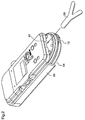
- Figure 1 is an external perspective view of the measuring system
- figure 2 is a perspective view of the measuring system seen from the bottom side
- figure 3 is an exploded perspective view of a biosensor (hereinafter, abbreviated to sensor).
- a sensor 29 shown in figure 3 is inserted to a connector 13, and liquid to be examined such as blood is applied to the end of the sensor 29, so that a measurement result in the measuring device 54 is sent to the optional equipment 56, thereby announcing the measurement result by voice from a voice output means 57 of the optional device 56.
- a counter electrode 5, a measuring electrode 4, leads 3 and 2 connected thereto, and an insulating layer 6 are provided on a substrate 1 of the sensor 29 as shown in figure 3.
- a reactive layer, which is not shown, which includes enzyme and a mediator (electron acceptor) is formed as if the counter electrode 5 and the measuring electrode 4 are covered therewith.
- a cover 9 is fixed on the substrate 1 through the intermediary of a spacer 7.
- Numeral 8 denotes a sample supply opening, from where liquid to be examined (sample) is introduced onto the counter electrode 5 and the measuring electrode 4 by capillarity. The air inside is discharged from an air vent 10 together with the introduction of the liquid to be examined.
- Numeral 11 denotes a projection for preventing an inverse insertion, by which a reverse insertion to the body of the measuring device 54 can be prevented.
- Figure 4 is a side view of the measuring system.
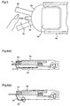
- Figure 5 is a plan view illustrating a sectional construction of a guide 50 for applying body fluid to the sensor and a sensor hold part in the measuring system.
- the guide 50 is inserted to a guide insertion slot 42 of the optional equipment 56, the sensor 29 is inserted to the connector 13 of the measuring device 54, thereby to employ the guide 50 as a guiding means for a fingertip.
- a measurement operator moves his/her fingertip to the end of the sensor 29 along a guiding groove 55 for guiding a fingertip, which is provided in the guide 50, thereby to perform an applying operation of prescribed body fluid, as shown in figure 5.
- the guide is V-shape in the embodiment, it may have any other shapes than the V-shape if only there is a groove which leads a fingertip to the end of the measuring device where the sensor is attached.
- a prescribed measurement result concerning the body fluid is notified by voice or pressure by an optional equipment 56, or a display means 30 such as a LCD of the measuring device 54 due to progress of an enzyme reaction.
- the measurement operator confirms the position of the sensor 29 by the guide 50 to be a mark, and concludes the operation by taking the sensor 29 out of the connector 31.
- the guide 50 is attached to the optional equipment 56 which is thought to be attached to the measuring device 54 in a case of a usage by a blind person, a person having a weak eyesight or an elderly person, or is insertedly fitted to a fitting part of the measuring device 54 and the optional equipment 56.
- the guide 50 is in a conformation as shown in above-described figure 4.
- the guide 50 can be used as a clamp for unitedly fixing the measuring device 54 and the optional equipment 56 as shown in figures 6(a) and (b).
- the guide 50 is stored into the optional equipment 56 in an arrow direction by a sliding system, which results in a compact shape.
- the guide 50 can be constructed to rotate around a supporting point 53 of the optional equipment 56. In either case, the end of the guide 50 is inflected, thereby to obtain a clampable shape at the end of the measuring device 54.
- a material of the guide 50 a material especially having a spring elasticity (such as SUS material or Duracon) is employed, so that the guide can be employed as a stronger clamp due to its own spring elasticity.
- the guide 50 when the guide 50 is employed, it is possible to remove difficulty of locating operations when a blind person or a person having a weak eyesight attaches/detaches the sensor 29 to/from the measuring device 54, or applies body fluid such as blood of a fingertip to the end of the sensor 29, thereby reducing troubles or labors of the operations at the usage. Further, the mechanism for guiding a target to be measured to the sensor 29 can be realized by a simple construction such as the guide 50.
- the senor 29 a type of a sensor which utilizes capillarity as a method of leading blood to an enzyme electrode part is described. Though, even when a sensor which drops blood directly to the enzyme electrode part can be employed, the same effects can be obtained.
- the guide 50 may be constructed to be attached to the measuring electrode 54 directly, in addition to construction as described in the above-mentioned embodiment.
- the guide 50 may be detachable from the measuring device 54, or may have construction similar to that shown in figure 6, in which the guide 50 may be constructed to be stored into the measuring device 54 by a sliding system, or may be supported to rotate freely.
- a measuring system can remove difficulty of locating operations when a sensor is attached/detached to/from a measuring device or body fluid such as blood of a fingertip is applied to the end of the sensor, and more particularly, the measuring system is available when its user is a blind person or a person having a weak eyesight, resulting in reduction of troubles or labors of the operation at the usage.
Landscapes
- Health & Medical Sciences (AREA)
- Engineering & Computer Science (AREA)
- Life Sciences & Earth Sciences (AREA)
- Biomedical Technology (AREA)
- Physics & Mathematics (AREA)
- Chemical & Material Sciences (AREA)
- Medicinal Chemistry (AREA)
- General Physics & Mathematics (AREA)
- Molecular Biology (AREA)
- Urology & Nephrology (AREA)
- Optics & Photonics (AREA)
- Food Science & Technology (AREA)
- Hematology (AREA)
- Biochemistry (AREA)
- Biophysics (AREA)
- General Health & Medical Sciences (AREA)
- Analytical Chemistry (AREA)
- Immunology (AREA)
- Pathology (AREA)
- Investigating Or Analysing Biological Materials (AREA)
- Measurement Of The Respiration, Hearing Ability, Form, And Blood Characteristics Of Living Organisms (AREA)
Abstract
Description
Claims (11)
- A measuring system comprising a sensor and a measuring device for assaying a specified component in a biological sample applied to the sensor, in which a new sensor is mounted to the measuring device at every time when a property of a target to be measured is measured, so as to perform a measurement, including:
a guide for guiding the target to be measured to the sensor. - The measuring system as defined in Claim 1, wherein
the guide is provided at the forward side of the measurement part of the sensor. - The measuring system as defined in Claim 1, wherein
the guide can be pulled out of or stored in the measuring device. - A measuring system comprising a sensor, a measuring device for assaying a specified component in a biological sample applied to the sensor, and an optional equipment which announces a measurement result by the measuring device or the like by voice, in which a new sensor is mounted to the measuring device at every time when a property of a target to be measured is measured, so as to perform a measurement, wherein
a guide for guiding the target to be measured to the sensor is mounted to the side of the optional equipment. - The measuring system as defined in Claim 4, wherein
the guide is employed as a clamp for fixing the measuring device with the optional equipment. - The measuring system as defined in Claim 4, wherein
the guide can be pulled out of or stored in the optional equipment. - The measuring system as defined in Claim 1, wherein
the guide is V-shape so as to guide a fingertip to the sensor to which the target to be measured is applied. - The measuring system as defined in Claim 7, wherein
the guide is made of a material having a spring elasticity. - The measuring system as defined in Claim 7, wherein
the guide has a groove formed from the end of the measuring device. - The measuring system as defined in Claim 5, wherein
the guide pushes the end or top surface of the measuring device. - The measuring system as defined in Claim 4, wherein
the guide is removable from the optional equipment.
Applications Claiming Priority (3)
| Application Number | Priority Date | Filing Date | Title |
|---|---|---|---|
| JP2000041714 | 2000-02-18 | ||
| JP2000041714 | 2000-02-18 | ||
| PCT/JP2001/001151 WO2001061341A1 (en) | 2000-02-18 | 2001-02-19 | Measuring system |
Publications (3)
| Publication Number | Publication Date |
|---|---|
| EP1172652A1 true EP1172652A1 (en) | 2002-01-16 |
| EP1172652A4 EP1172652A4 (en) | 2003-07-16 |
| EP1172652B1 EP1172652B1 (en) | 2015-06-10 |
Family
ID=18564906
Family Applications (1)
| Application Number | Title | Priority Date | Filing Date |
|---|---|---|---|
| EP01904530.1A Expired - Lifetime EP1172652B1 (en) | 2000-02-18 | 2001-02-19 | Measuring system |
Country Status (5)
| Country | Link |
|---|---|
| US (1) | US7147825B2 (en) |
| EP (1) | EP1172652B1 (en) |
| JP (1) | JP4646477B2 (en) |
| CN (1) | CN1153968C (en) |
| WO (1) | WO2001061341A1 (en) |
Cited By (1)
| Publication number | Priority date | Publication date | Assignee | Title |
|---|---|---|---|---|
| WO2003068071A1 (en) | 2002-02-15 | 2003-08-21 | Arkray, Inc. | Integrally storable adaptor |
Families Citing this family (80)
| Publication number | Priority date | Publication date | Assignee | Title |
|---|---|---|---|---|
| US6036924A (en) | 1997-12-04 | 2000-03-14 | Hewlett-Packard Company | Cassette of lancet cartridges for sampling blood |
| US8071384B2 (en) | 1997-12-22 | 2011-12-06 | Roche Diagnostics Operations, Inc. | Control and calibration solutions and methods for their use |
| US6391005B1 (en) | 1998-03-30 | 2002-05-21 | Agilent Technologies, Inc. | Apparatus and method for penetration with shaft having a sensor for sensing penetration depth |
| DE10057832C1 (en) | 2000-11-21 | 2002-02-21 | Hartmann Paul Ag | Blood analysis device has syringe mounted in casing, annular mounting carrying needles mounted behind test strip and being swiveled so that needle can be pushed through strip and aperture in casing to take blood sample |
| US8641644B2 (en) | 2000-11-21 | 2014-02-04 | Sanofi-Aventis Deutschland Gmbh | Blood testing apparatus having a rotatable cartridge with multiple lancing elements and testing means |
| US7537571B2 (en) | 2001-06-12 | 2009-05-26 | Pelikan Technologies, Inc. | Integrated blood sampling analysis system with multi-use sampling module |
| WO2002100460A2 (en) | 2001-06-12 | 2002-12-19 | Pelikan Technologies, Inc. | Electric lancet actuator |
| CA2448902C (en) | 2001-06-12 | 2010-09-07 | Pelikan Technologies, Inc. | Self optimizing lancing device with adaptation means to temporal variations in cutaneous properties |
| US7041068B2 (en) | 2001-06-12 | 2006-05-09 | Pelikan Technologies, Inc. | Sampling module device and method |
| WO2002100461A2 (en) | 2001-06-12 | 2002-12-19 | Pelikan Technologies, Inc. | Method and apparatus for improving success rate of blood yield from a fingerstick |
| US9226699B2 (en) | 2002-04-19 | 2016-01-05 | Sanofi-Aventis Deutschland Gmbh | Body fluid sampling module with a continuous compression tissue interface surface |
| US7682318B2 (en) | 2001-06-12 | 2010-03-23 | Pelikan Technologies, Inc. | Blood sampling apparatus and method |
| US7981056B2 (en) | 2002-04-19 | 2011-07-19 | Pelikan Technologies, Inc. | Methods and apparatus for lancet actuation |
| US7344507B2 (en) | 2002-04-19 | 2008-03-18 | Pelikan Technologies, Inc. | Method and apparatus for lancet actuation |
| US8337419B2 (en) | 2002-04-19 | 2012-12-25 | Sanofi-Aventis Deutschland Gmbh | Tissue penetration device |
| AU2002348683A1 (en) | 2001-06-12 | 2002-12-23 | Pelikan Technologies, Inc. | Method and apparatus for lancet launching device integrated onto a blood-sampling cartridge |
| US9795747B2 (en) | 2010-06-02 | 2017-10-24 | Sanofi-Aventis Deutschland Gmbh | Methods and apparatus for lancet actuation |
| US9427532B2 (en) | 2001-06-12 | 2016-08-30 | Sanofi-Aventis Deutschland Gmbh | Tissue penetration device |
| US7344894B2 (en) | 2001-10-16 | 2008-03-18 | Agilent Technologies, Inc. | Thermal regulation of fluidic samples within a diagnostic cartridge |
| US7901362B2 (en) | 2002-04-19 | 2011-03-08 | Pelikan Technologies, Inc. | Method and apparatus for penetrating tissue |
| US7491178B2 (en) | 2002-04-19 | 2009-02-17 | Pelikan Technologies, Inc. | Method and apparatus for penetrating tissue |
| US7371247B2 (en) | 2002-04-19 | 2008-05-13 | Pelikan Technologies, Inc | Method and apparatus for penetrating tissue |
| US7297122B2 (en) | 2002-04-19 | 2007-11-20 | Pelikan Technologies, Inc. | Method and apparatus for penetrating tissue |
| US7563232B2 (en) | 2002-04-19 | 2009-07-21 | Pelikan Technologies, Inc. | Method and apparatus for penetrating tissue |
| US7909778B2 (en) | 2002-04-19 | 2011-03-22 | Pelikan Technologies, Inc. | Method and apparatus for penetrating tissue |
| US7976476B2 (en) | 2002-04-19 | 2011-07-12 | Pelikan Technologies, Inc. | Device and method for variable speed lancet |
| US9248267B2 (en) | 2002-04-19 | 2016-02-02 | Sanofi-Aventis Deustchland Gmbh | Tissue penetration device |
| US8221334B2 (en) | 2002-04-19 | 2012-07-17 | Sanofi-Aventis Deutschland Gmbh | Method and apparatus for penetrating tissue |
| US8702624B2 (en) | 2006-09-29 | 2014-04-22 | Sanofi-Aventis Deutschland Gmbh | Analyte measurement device with a single shot actuator |
| US7141058B2 (en) | 2002-04-19 | 2006-11-28 | Pelikan Technologies, Inc. | Method and apparatus for a body fluid sampling device using illumination |
| US7481776B2 (en) | 2002-04-19 | 2009-01-27 | Pelikan Technologies, Inc. | Method and apparatus for penetrating tissue |
| US7582099B2 (en) | 2002-04-19 | 2009-09-01 | Pelikan Technologies, Inc | Method and apparatus for penetrating tissue |
| US9795334B2 (en) | 2002-04-19 | 2017-10-24 | Sanofi-Aventis Deutschland Gmbh | Method and apparatus for penetrating tissue |
| US7410468B2 (en) | 2002-04-19 | 2008-08-12 | Pelikan Technologies, Inc. | Method and apparatus for penetrating tissue |
| US8579831B2 (en) | 2002-04-19 | 2013-11-12 | Sanofi-Aventis Deutschland Gmbh | Method and apparatus for penetrating tissue |
| US7892183B2 (en) | 2002-04-19 | 2011-02-22 | Pelikan Technologies, Inc. | Method and apparatus for body fluid sampling and analyte sensing |
| US7291117B2 (en) | 2002-04-19 | 2007-11-06 | Pelikan Technologies, Inc. | Method and apparatus for penetrating tissue |
| US7232451B2 (en) | 2002-04-19 | 2007-06-19 | Pelikan Technologies, Inc. | Method and apparatus for penetrating tissue |
| US7331931B2 (en) | 2002-04-19 | 2008-02-19 | Pelikan Technologies, Inc. | Method and apparatus for penetrating tissue |
| US8267870B2 (en) | 2002-04-19 | 2012-09-18 | Sanofi-Aventis Deutschland Gmbh | Method and apparatus for body fluid sampling with hybrid actuation |
| US7226461B2 (en) | 2002-04-19 | 2007-06-05 | Pelikan Technologies, Inc. | Method and apparatus for a multi-use body fluid sampling device with sterility barrier release |
| US7648468B2 (en) | 2002-04-19 | 2010-01-19 | Pelikon Technologies, Inc. | Method and apparatus for penetrating tissue |
| US7717863B2 (en) | 2002-04-19 | 2010-05-18 | Pelikan Technologies, Inc. | Method and apparatus for penetrating tissue |
| US7374544B2 (en) | 2002-04-19 | 2008-05-20 | Pelikan Technologies, Inc. | Method and apparatus for penetrating tissue |
| US7674232B2 (en) | 2002-04-19 | 2010-03-09 | Pelikan Technologies, Inc. | Method and apparatus for penetrating tissue |
| US7547287B2 (en) | 2002-04-19 | 2009-06-16 | Pelikan Technologies, Inc. | Method and apparatus for penetrating tissue |
| US7524293B2 (en) | 2002-04-19 | 2009-04-28 | Pelikan Technologies, Inc. | Method and apparatus for penetrating tissue |
| US8784335B2 (en) | 2002-04-19 | 2014-07-22 | Sanofi-Aventis Deutschland Gmbh | Body fluid sampling device with a capacitive sensor |
| US7229458B2 (en) | 2002-04-19 | 2007-06-12 | Pelikan Technologies, Inc. | Method and apparatus for penetrating tissue |
| US9314194B2 (en) | 2002-04-19 | 2016-04-19 | Sanofi-Aventis Deutschland Gmbh | Tissue penetration device |
| US8574895B2 (en) | 2002-12-30 | 2013-11-05 | Sanofi-Aventis Deutschland Gmbh | Method and apparatus using optical techniques to measure analyte levels |
| ES2490740T3 (en) | 2003-06-06 | 2014-09-04 | Sanofi-Aventis Deutschland Gmbh | Apparatus for blood fluid sampling and analyte detection |
| WO2006001797A1 (en) | 2004-06-14 | 2006-01-05 | Pelikan Technologies, Inc. | Low pain penetrating |
| US7604592B2 (en) | 2003-06-13 | 2009-10-20 | Pelikan Technologies, Inc. | Method and apparatus for a point of care device |
| US7645373B2 (en) | 2003-06-20 | 2010-01-12 | Roche Diagnostic Operations, Inc. | System and method for coding information on a biosensor test strip |
| US7645421B2 (en) | 2003-06-20 | 2010-01-12 | Roche Diagnostics Operations, Inc. | System and method for coding information on a biosensor test strip |
| US7718439B2 (en) | 2003-06-20 | 2010-05-18 | Roche Diagnostics Operations, Inc. | System and method for coding information on a biosensor test strip |
| US8148164B2 (en) | 2003-06-20 | 2012-04-03 | Roche Diagnostics Operations, Inc. | System and method for determining the concentration of an analyte in a sample fluid |
| US8058077B2 (en) | 2003-06-20 | 2011-11-15 | Roche Diagnostics Operations, Inc. | Method for coding information on a biosensor test strip |
| US7604721B2 (en) | 2003-06-20 | 2009-10-20 | Roche Diagnostics Operations, Inc. | System and method for coding information on a biosensor test strip |
| US7597793B2 (en) | 2003-06-20 | 2009-10-06 | Roche Operations Ltd. | System and method for analyte measurement employing maximum dosing time delay |
| US8206565B2 (en) | 2003-06-20 | 2012-06-26 | Roche Diagnostics Operation, Inc. | System and method for coding information on a biosensor test strip |
| US7452457B2 (en) | 2003-06-20 | 2008-11-18 | Roche Diagnostics Operations, Inc. | System and method for analyte measurement using dose sufficiency electrodes |
| EP1671096A4 (en) | 2003-09-29 | 2009-09-16 | Pelikan Technologies Inc | METHOD AND APPARATUS FOR AN IMPROVED SAMPLING INTERFERENCE DEVICE |
| EP1680014A4 (en) | 2003-10-14 | 2009-01-21 | Pelikan Technologies Inc | METHOD AND APPARATUS PROVIDING A VARIABLE USER INTERFACE |
| US7822454B1 (en) | 2005-01-03 | 2010-10-26 | Pelikan Technologies, Inc. | Fluid sampling device with improved analyte detecting member configuration |
| WO2005065414A2 (en) | 2003-12-31 | 2005-07-21 | Pelikan Technologies, Inc. | Method and apparatus for improving fluidic flow and sample capture |
| US8828203B2 (en) | 2004-05-20 | 2014-09-09 | Sanofi-Aventis Deutschland Gmbh | Printable hydrogels for biosensors |
| EP1765194A4 (en) | 2004-06-03 | 2010-09-29 | Pelikan Technologies Inc | METHOD AND APPARATUS FOR MANUFACTURING A DEVICE FOR SAMPLING LIQUIDS |
| US7556723B2 (en) | 2004-06-18 | 2009-07-07 | Roche Diagnostics Operations, Inc. | Electrode design for biosensor |
| US7569126B2 (en) | 2004-06-18 | 2009-08-04 | Roche Diagnostics Operations, Inc. | System and method for quality assurance of a biosensor test strip |
| US8652831B2 (en) | 2004-12-30 | 2014-02-18 | Sanofi-Aventis Deutschland Gmbh | Method and apparatus for analyte measurement test time |
| JP5027819B2 (en) * | 2006-11-30 | 2012-09-19 | パナソニック株式会社 | Blood test equipment |
| CN101715555A (en) * | 2007-04-27 | 2010-05-26 | 艾伯特糖尿病护理公司 | Test strip identification using conductive patterns |
| WO2009116234A1 (en) * | 2008-03-21 | 2009-09-24 | アークレイ株式会社 | Medical device |
| EP2265324B1 (en) | 2008-04-11 | 2015-01-28 | Sanofi-Aventis Deutschland GmbH | Integrated analyte measurement system |
| US9375169B2 (en) | 2009-01-30 | 2016-06-28 | Sanofi-Aventis Deutschland Gmbh | Cam drive for managing disposable penetrating member actions with a single motor and motor and control system |
| US8965476B2 (en) | 2010-04-16 | 2015-02-24 | Sanofi-Aventis Deutschland Gmbh | Tissue penetration device |
| JP2012177677A (en) * | 2011-02-02 | 2012-09-13 | Arkray Inc | Analyzer |
| CN105301256A (en) * | 2015-11-30 | 2016-02-03 | 武汉璟泓万方堂医药科技股份有限公司 | Threshold prompt device and prompt method thereof |
Family Cites Families (7)
| Publication number | Priority date | Publication date | Assignee | Title |
|---|---|---|---|---|
| JPS623649A (en) | 1985-06-28 | 1987-01-09 | Omron Tateisi Electronics Co | Uric sugar measuring instrument |
| WO1989004474A1 (en) * | 1987-11-02 | 1989-05-18 | Biologix Inc. | A portable blood chemistry measuring apparatus |
| US5597532A (en) * | 1994-10-20 | 1997-01-28 | Connolly; James | Apparatus for determining substances contained in a body fluid |
| US5786584A (en) * | 1995-09-06 | 1998-07-28 | Eli Lilly And Company | Vial and cartridge reading device providing audio feedback for a blood glucose monitoring system |
| JP3604821B2 (en) * | 1996-07-18 | 2004-12-22 | 大日本印刷株式会社 | Body fluid analyzer |
| US6045756A (en) * | 1996-10-01 | 2000-04-04 | Texas Instruments Incorporated | Miniaturized integrated sensor platform |
| DE19781162C2 (en) | 1996-10-30 | 2002-05-23 | Mercury Diagnostics Inc | Test strips for the analysis of a body fluid sample and for evaluation in a test instrument |
-
2001
- 2001-02-19 CN CNB01800265XA patent/CN1153968C/en not_active Expired - Lifetime
- 2001-02-19 JP JP2001560679A patent/JP4646477B2/en not_active Expired - Lifetime
- 2001-02-19 WO PCT/JP2001/001151 patent/WO2001061341A1/en not_active Ceased
- 2001-02-19 EP EP01904530.1A patent/EP1172652B1/en not_active Expired - Lifetime
- 2001-02-19 US US09/958,888 patent/US7147825B2/en not_active Expired - Lifetime
Cited By (2)
| Publication number | Priority date | Publication date | Assignee | Title |
|---|---|---|---|---|
| WO2003068071A1 (en) | 2002-02-15 | 2003-08-21 | Arkray, Inc. | Integrally storable adaptor |
| EP1475038B1 (en) * | 2002-02-15 | 2011-01-19 | ARKRAY, Inc. | Kit with lancing tool and analyser |
Also Published As
| Publication number | Publication date |
|---|---|
| JP4646477B2 (en) | 2011-03-09 |
| WO2001061341A1 (en) | 2001-08-23 |
| CN1153968C (en) | 2004-06-16 |
| US20020155030A1 (en) | 2002-10-24 |
| EP1172652B1 (en) | 2015-06-10 |
| US7147825B2 (en) | 2006-12-12 |
| EP1172652A4 (en) | 2003-07-16 |
| CN1363040A (en) | 2002-08-07 |
Similar Documents
| Publication | Publication Date | Title |
|---|---|---|
| EP1172652B1 (en) | Measuring system | |
| JPWO2001061341A1 (en) | Measurement System | |
| JP3569228B2 (en) | Analytical measuring instrument with incision instrument | |
| RU2188425C2 (en) | Device usable in instrument for measuring concentration of substance under study in biological fluid sample | |
| JP3964009B2 (en) | Remote dose type analyte concentration meter | |
| RU2201595C2 (en) | Method for measuring concentration of a substance under study in biological fluid sample | |
| AU784699B2 (en) | Percutaneous biological fluid sampling and analyte measurement devices and methods | |
| EP1360933B1 (en) | Physiological sample collection devices and methods of using the same | |
| TWI453401B (en) | System and methods for determination of analyte concentration using time resolved amperometry | |
| JP2003185615A (en) | Determination of sample volume adequacy | |
| JPH04357449A (en) | Biosensor and biosensor measuring device | |
| AU2008245537A1 (en) | Test strip identification using conductive patterns | |
| AU2003227705B2 (en) | Sampling device for liquid samples | |
| RU2670215C1 (en) | Precise measurements of the analyte using the electrochemical test-strip for the determination of the time of the analyte measuring on the basis of the measured temperature, physical characteristics and estimation concentration of the analyte and their temperature-compensated values | |
| US20140138244A1 (en) | Test strip for a medical meter | |
| US20180321179A1 (en) | Methods and systems for hematocrit measurement | |
| KR20190112731A (en) | Determination of Analyte Concentrations in Physiological Fluids with Interferences | |
| EP2956765B1 (en) | System and method for measuring an analyte in a sample and calculating hematocrit-insensitive glucose concentrations | |
| US20030077205A1 (en) | Diagnostic test optical fiber tips | |
| CN103533890A (en) | Analysis system having a measurement device and a testing element | |
| HK1217537B (en) | System and method for measuring an analyte in a sample and calculating hematocrit-insensitive glucose concentrations | |
| HK1189481A (en) | Analysis system having a measurement device and a testing element | |
| HK1055463B (en) | Determination of sample volume adequacy in biosensor devices |
Legal Events
| Date | Code | Title | Description |
|---|---|---|---|
| PUAI | Public reference made under article 153(3) epc to a published international application that has entered the european phase |
Free format text: ORIGINAL CODE: 0009012 |
|
| 17P | Request for examination filed |
Effective date: 20011106 |
|
| AK | Designated contracting states |
Kind code of ref document: A1 Designated state(s): AT BE CH CY DE DK ES FI FR GB GR IE IT LI LU MC NL PT SE TR |
|
| A4 | Supplementary search report drawn up and despatched |
Effective date: 20030604 |
|
| RIC1 | Information provided on ipc code assigned before grant |
Ipc: 7G 01N 33/487 B Ipc: 7A 61B 5/00 B Ipc: 7G 01N 33/48 A |
|
| RBV | Designated contracting states (corrected) |
Designated state(s): DE FR GB IT |
|
| 17Q | First examination report despatched |
Effective date: 20071129 |
|
| RAP1 | Party data changed (applicant data changed or rights of an application transferred) |
Owner name: ARKRAY, INC. Owner name: PANASONIC CORPORATION |
|
| RAP1 | Party data changed (applicant data changed or rights of an application transferred) |
Owner name: PANASONIC HEALTHCARE CO., LTD. Owner name: ARKRAY, INC. |
|
| GRAP | Despatch of communication of intention to grant a patent |
Free format text: ORIGINAL CODE: EPIDOSNIGR1 |
|
| INTG | Intention to grant announced |
Effective date: 20150313 |
|
| RIN1 | Information on inventor provided before grant (corrected) |
Inventor name: SATO, YOSHIHARU Inventor name: MATSUDA, KOUICHI Inventor name: WATANABE, MASASHI Inventor name: HIRAO, ETSUO |
|
| GRAS | Grant fee paid |
Free format text: ORIGINAL CODE: EPIDOSNIGR3 |
|
| GRAA | (expected) grant |
Free format text: ORIGINAL CODE: 0009210 |
|
| AK | Designated contracting states |
Kind code of ref document: B1 Designated state(s): DE FR GB IT |
|
| REG | Reference to a national code |
Ref country code: GB Ref legal event code: FG4D |
|
| REG | Reference to a national code |
Ref country code: DE Ref legal event code: R096 Ref document number: 60149399 Country of ref document: DE |
|
| RAP2 | Party data changed (patent owner data changed or rights of a patent transferred) |
Owner name: ARKRAY, INC. Owner name: PANASONIC HEALTHCARE CO., LTD. |
|
| REG | Reference to a national code |
Ref country code: FR Ref legal event code: PLFP Year of fee payment: 16 |
|
| REG | Reference to a national code |
Ref country code: DE Ref legal event code: R097 Ref document number: 60149399 Country of ref document: DE |
|
| PLBE | No opposition filed within time limit |
Free format text: ORIGINAL CODE: 0009261 |
|
| STAA | Information on the status of an ep patent application or granted ep patent |
Free format text: STATUS: NO OPPOSITION FILED WITHIN TIME LIMIT |
|
| 26N | No opposition filed |
Effective date: 20160311 |
|
| REG | Reference to a national code |
Ref country code: FR Ref legal event code: PLFP Year of fee payment: 17 |
|
| REG | Reference to a national code |
Ref country code: FR Ref legal event code: PLFP Year of fee payment: 18 |
|
| REG | Reference to a national code |
Ref country code: DE Ref legal event code: R082 Ref document number: 60149399 Country of ref document: DE Representative=s name: NOVAGRAAF BREVETS, FR Ref country code: DE Ref legal event code: R081 Ref document number: 60149399 Country of ref document: DE Owner name: ARKRAY, INC., JP Free format text: FORMER OWNERS: ARKRAY, INC., KYOTO, JP; PANASONIC HEALTHCARE CO., LTD., TOON-SHI, EHIME, JP Ref country code: DE Ref legal event code: R081 Ref document number: 60149399 Country of ref document: DE Owner name: PHC CORP., TOON-SHI, JP Free format text: FORMER OWNERS: ARKRAY, INC., KYOTO, JP; PANASONIC HEALTHCARE CO., LTD., TOON-SHI, EHIME, JP |
|
| REG | Reference to a national code |
Ref country code: FR Ref legal event code: CD Owner name: ARKRAY, INC., JP Effective date: 20181012 Ref country code: FR Ref legal event code: CD Owner name: PHC CORPORATION, JP Effective date: 20181012 |
|
| PGFP | Annual fee paid to national office [announced via postgrant information from national office to epo] |
Ref country code: GB Payment date: 20200212 Year of fee payment: 20 Ref country code: DE Payment date: 20200204 Year of fee payment: 20 Ref country code: IT Payment date: 20200128 Year of fee payment: 20 |
|
| PGFP | Annual fee paid to national office [announced via postgrant information from national office to epo] |
Ref country code: FR Payment date: 20200113 Year of fee payment: 20 |
|
| REG | Reference to a national code |
Ref country code: DE Ref legal event code: R071 Ref document number: 60149399 Country of ref document: DE |
|
| REG | Reference to a national code |
Ref country code: GB Ref legal event code: PE20 Expiry date: 20210218 |
|
| PG25 | Lapsed in a contracting state [announced via postgrant information from national office to epo] |
Ref country code: GB Free format text: LAPSE BECAUSE OF EXPIRATION OF PROTECTION Effective date: 20210218 |