EP1172598B1 - Double-walled structure and connection arrangement for it - Google Patents
Double-walled structure and connection arrangement for it Download PDFInfo
- Publication number
- EP1172598B1 EP1172598B1 EP20010850103 EP01850103A EP1172598B1 EP 1172598 B1 EP1172598 B1 EP 1172598B1 EP 20010850103 EP20010850103 EP 20010850103 EP 01850103 A EP01850103 A EP 01850103A EP 1172598 B1 EP1172598 B1 EP 1172598B1
- Authority
- EP
- European Patent Office
- Prior art keywords
- outer casing
- double
- inner tube
- segments
- segment
- Prior art date
- Legal status (The legal status is an assumption and is not a legal conclusion. Google has not performed a legal analysis and makes no representation as to the accuracy of the status listed.)
- Expired - Lifetime
Links
- 230000008878 coupling Effects 0.000 claims abstract description 22
- 238000010168 coupling process Methods 0.000 claims abstract description 22
- 238000005859 coupling reaction Methods 0.000 claims abstract description 22
- 239000011810 insulating material Substances 0.000 claims abstract description 9
- 238000007789 sealing Methods 0.000 claims description 10
- 239000000463 material Substances 0.000 claims description 9
- 238000009423 ventilation Methods 0.000 claims description 7
- 239000000945 filler Substances 0.000 claims description 5
- 239000011358 absorbing material Substances 0.000 claims description 3
- 238000003780 insertion Methods 0.000 claims description 2
- 230000037431 insertion Effects 0.000 claims description 2
- 238000009413 insulation Methods 0.000 abstract description 9
- 238000010420 art technique Methods 0.000 description 3
- 238000009833 condensation Methods 0.000 description 3
- 230000005494 condensation Effects 0.000 description 3
- 239000002657 fibrous material Substances 0.000 description 3
- 230000002265 prevention Effects 0.000 description 3
- 230000006835 compression Effects 0.000 description 2
- 238000007906 compression Methods 0.000 description 2
- 239000000853 adhesive Substances 0.000 description 1
- 230000001070 adhesive effect Effects 0.000 description 1
- 230000000694 effects Effects 0.000 description 1
- 239000011152 fibreglass Substances 0.000 description 1
- 238000011010 flushing procedure Methods 0.000 description 1
- 239000003365 glass fiber Substances 0.000 description 1
- 238000009434 installation Methods 0.000 description 1
- 238000004519 manufacturing process Methods 0.000 description 1
- 239000012858 resilient material Substances 0.000 description 1
- 230000029058 respiratory gaseous exchange Effects 0.000 description 1
- 238000005096 rolling process Methods 0.000 description 1
- 238000007665 sagging Methods 0.000 description 1
- 238000004826 seaming Methods 0.000 description 1
- 230000003584 silencer Effects 0.000 description 1
- 239000007787 solid Substances 0.000 description 1
- 210000002268 wool Anatomy 0.000 description 1
Images

Classifications
-
- F—MECHANICAL ENGINEERING; LIGHTING; HEATING; WEAPONS; BLASTING
- F24—HEATING; RANGES; VENTILATING
- F24F—AIR-CONDITIONING; AIR-HUMIDIFICATION; VENTILATION; USE OF AIR CURRENTS FOR SCREENING
- F24F13/00—Details common to, or for air-conditioning, air-humidification, ventilation or use of air currents for screening
- F24F13/02—Ducting arrangements
- F24F13/0263—Insulation for air ducts
-
- F—MECHANICAL ENGINEERING; LIGHTING; HEATING; WEAPONS; BLASTING
- F16—ENGINEERING ELEMENTS AND UNITS; GENERAL MEASURES FOR PRODUCING AND MAINTAINING EFFECTIVE FUNCTIONING OF MACHINES OR INSTALLATIONS; THERMAL INSULATION IN GENERAL
- F16L—PIPES; JOINTS OR FITTINGS FOR PIPES; SUPPORTS FOR PIPES, CABLES OR PROTECTIVE TUBING; MEANS FOR THERMAL INSULATION IN GENERAL
- F16L39/00—Joints or fittings for double-walled or multi-channel pipes or pipe assemblies
- F16L39/005—Joints or fittings for double-walled or multi-channel pipes or pipe assemblies for concentric pipes
-
- F—MECHANICAL ENGINEERING; LIGHTING; HEATING; WEAPONS; BLASTING
- F16—ENGINEERING ELEMENTS AND UNITS; GENERAL MEASURES FOR PRODUCING AND MAINTAINING EFFECTIVE FUNCTIONING OF MACHINES OR INSTALLATIONS; THERMAL INSULATION IN GENERAL
- F16L—PIPES; JOINTS OR FITTINGS FOR PIPES; SUPPORTS FOR PIPES, CABLES OR PROTECTIVE TUBING; MEANS FOR THERMAL INSULATION IN GENERAL
- F16L59/00—Thermal insulation in general
- F16L59/14—Arrangements for the insulation of pipes or pipe systems
- F16L59/143—Pre-insulated pipes
-
- F—MECHANICAL ENGINEERING; LIGHTING; HEATING; WEAPONS; BLASTING
- F23—COMBUSTION APPARATUS; COMBUSTION PROCESSES
- F23J—REMOVAL OR TREATMENT OF COMBUSTION PRODUCTS OR COMBUSTION RESIDUES; FLUES
- F23J13/00—Fittings for chimneys or flues
- F23J13/02—Linings; Jackets; Casings
- F23J13/025—Linings; Jackets; Casings composed of concentric elements, e.g. double walled
-
- F—MECHANICAL ENGINEERING; LIGHTING; HEATING; WEAPONS; BLASTING
- F23—COMBUSTION APPARATUS; COMBUSTION PROCESSES
- F23J—REMOVAL OR TREATMENT OF COMBUSTION PRODUCTS OR COMBUSTION RESIDUES; FLUES
- F23J13/00—Fittings for chimneys or flues
- F23J13/04—Joints; Connections
-
- F—MECHANICAL ENGINEERING; LIGHTING; HEATING; WEAPONS; BLASTING
- F23—COMBUSTION APPARATUS; COMBUSTION PROCESSES
- F23J—REMOVAL OR TREATMENT OF COMBUSTION PRODUCTS OR COMBUSTION RESIDUES; FLUES
- F23J2213/00—Chimneys or flues
- F23J2213/20—Joints; Connections
- F23J2213/202—Joints; Connections between duct or stack sections
-
- Y—GENERAL TAGGING OF NEW TECHNOLOGICAL DEVELOPMENTS; GENERAL TAGGING OF CROSS-SECTIONAL TECHNOLOGIES SPANNING OVER SEVERAL SECTIONS OF THE IPC; TECHNICAL SUBJECTS COVERED BY FORMER USPC CROSS-REFERENCE ART COLLECTIONS [XRACs] AND DIGESTS
- Y10—TECHNICAL SUBJECTS COVERED BY FORMER USPC
- Y10T—TECHNICAL SUBJECTS COVERED BY FORMER US CLASSIFICATION
- Y10T137/00—Fluid handling
- Y10T137/5762—With leakage or drip collecting
Definitions
- the invention relates to a double-walled structure, such as double-walled segment, preferably for use in ventilation ductwork systems.
- the invention also relates to a connection arrangement for coupling together two double-walled segments, preferably for use in a ventilation ductwork system.
- Double-walled structures for use in ventilation duct systems are well known in the art. Such double-walled structures may be comprised of a one piece straight elongated duct, an elbow, a connecting element, a silencer, etc.
- Double-walled structure refers to a structure having an inner tube forming an inner wall of the structure, and an outer casing, being spaced from the inner wall and forming the outer wall of the structure. The space between the inner and outer walls is filled by insulating material, e.g. a sound insulating or absorbing material.
- a sound absorbing double-walled structure having its inner tube or inner wall formed in the shape of a helically-wound lock-seam tubing and an outer casing, and having its outer casing or outer wall typically also formed of a helically-wound lock-seam tubing.
- the inner tube is perforated, and the sound absorbing material in the space between the inner tube and the outer casing is preferably wool.
- duct systems including double-walled duct systems for ventilation purposes, in buildings
- two similar or different segments such as straight elongated segments, elbows, etc.
- one of the two segments to be coupled together is provided, at one end, with a female portion and the other of the two segments to be coupled together is provided, at one end, with a male portion, which one ends of the two segments are designed such that the male and female end portions can be interconnected with a fit, such as a slip fit.
- the male portion may have a gasket, such as a lip seal, on its outer circumference for sealing against the inner circumference of the female portion, when the segments are coupled together.
- Coupling together of two double-walled segments with a male portion and a female portion, respectively, at one end is more complicated than coupling together of two single-walled segments.
- interconnecting of the male and female end portions of two double-walled segments requires, in fact, connecting of four tubings, which connecting, to be time-effective, should be done simultaneously, in a single push-together movement.
- no such perfect alignment can be achieved quickly in practical application, especially not when the coupling of the segments is to be done in overhead areas, e.g. near the ceiling of a building, requiring raised arms of the installer, or in confined spaces.
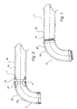
- the difficulty involved is illustrated in Fig.
- US-A-4 502 370 discloses a chimney assembly comprising sections each including concentric outer, intermediate and inner sleeves. The space between the outer sleeve and intermediate sleeve is filled with a filler material. An annular ring is positioned between the lower portions of the outer sleeve and the intermediate sleeve. This chimney assembly is intended for providing high temperature insulative properties.
- An object of the invention is to eliminate the drawbacks mentioned above by providing an improved double-walled structure, making it possible to connect two double-walled segments together in a simple way.
- This object is achieved by a double-walled structure according to the attached independent claims, preferred embodiments being defined in the sub-claims;
- the structure according to the invention requires only that the outer casings of two double-walled segments to be coupled together have a male part and a female part, respectively, to be interconnected, making the coupling easier than the prior art technique, requiring coupling of four tubes.
- the seal(s) provide support when carrying out the connection of the male/female ends of the two outer casings and isolate the insulation from the air stream in a ventilation ductwork system.
- the seals further have the function of the batting/filling in the space between the inner tubes and outer casings of the segments, e.g. a sound absorbing function, and/or a thermal insulation function in the joint between the coupled segments, and have a portion protruding beyond the free end of the inner tube.
- Segment 1 has an inner tube 1A and an outer casing 1B
- segment 2 has an inner tube 2A and an outer casing 2B.
- Tube and casing 1A, 1B are circular in cross section and concentric and tube and casing 2A, 2B are circular in cross section and concentric.
- the double-walled segment 1 and/or 2 can be straight or bent (be e.g. an elbow) or can have other configuration, having at least one end designed, according to the invention, for connection to one end, of possibly several ends, of another double-walled segment.
- segments 1 or 2 can each have e.g. X- or Y-configuration, having four or three, respectively, connecting end portions.
- segment 2 is an elbow and segment 1 can be a straight segment , which segments are to be coupled together as parts of a silenced ductwork system.
- the segments illustrated here are made up by locked seamed portions, as illustrated by the reference sign L in Fig. 3.
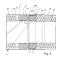
- Fig. 3 illustrates connected end portions of segments 1 and 2 corresponding to the facing end portions of segments 1 and 2 of Fig. 2, but can represent connected end portions of segments 1 and 2 of whatever kind (stright/elbow/X-/Y-pieces or fittings).
- the one end portion of segment 1 has a female portion 1F and the one end portion of segment 2 has a male portion 2M.
- the female and male end portions 1F and 2M are designed for a slip or slide fit together, coupling the sections 1, 2 together by interconnecting the female and male portions 1F and 2M.
- the inner tubes 1A and 2A of segments 1, 2 have the same diameter, which is, however, not necessary, i.e. the inner tubes 1A and 2A can have different diameters.
- the outer diameter of the casing 2B is smaller than the outer diameter of the casing 1B in the female end portion 1F of segment 1, such that the male portion of segment 2 can be pushed into the female portion of segment 1 with a slip fit.
- the male portion of segment 2 may have a recess 5 occupied by a gasket 6, defining a pressure leak stop to the outside.
- Such a stop in form of an outward bulge in the outer casing of the male part of double-walled segments intended for coupling is common within the art.
- a seal is provided in the female and male end portions 1F and 2M, respectively, of the segments 1 and 2.
- These seals are denoted 1S and 2S. They are of an resilient material and in a relaxed state tubes of rubber or a similar material, capable of being compressed, in the diameter direction, and thereafter pushed into the female and male end portions 1F and 2M of the segments 1 and 2, between the inner tube 1A and the outer casing 1B and between the inner tube 2A and the outer casing 2B, respectively, with a snug fit.
- the seal 1S is placed between tube 1A and outer casing 1B in such a way that it fills the space between a free end portion of the retracted inner tube 1A and the opposite portion of the outer casing 1B, protruding slightly beyond the free end of tube 1A, leaving the female end portion of the outer casing 1B free for connection to the segment 2.
- the seal 2S is placed between the flushing end portions of tube 2A and the outer casing 2B protruding slightly beyond the free ends thereof.
- the seals 1S, 2S are provided for meeting in the gap G, thereby closing off the gap G between the inner tubes 1A and 2A, when the segments 1 and 2 are connected.
- the seals 1S, 2S not only prevent the fibrous material of the sound absorbing batting 1C and 2C from being drawn into the inner tubes 1A and 2A, via the gap G, but they also form a sound absorbing bridge between the sound absorbing battings 1C and 2C. They further form a thermal insulation in the coupling joint between the segments 1 and 2, thereby preventing or hampering condensation on the outer surface of the connection joint.
- the seals 1S and 2S do not meet in the gap G.
- the main task can simply be to couple the two segments 1, 2 together in a simple way, I by connecting only the outer casings thereof, without regard to insulation aspects in the joint, with a simple pushing together movement, as referred to above.
- the seals 1S, 2S will also in such an embodiment keep the distance between the inner tube-outer casing combinations 1A, 1B and 2A, 2B, respectively, thereby preventing sagging of the joint between the segments 1 and 2.
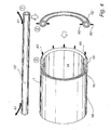
- Fig. 4 illustrates the above mentioned steps of placing a seal 1S (or 2S).
- Stage 1 denoted with 1 within a circle, is providing a straight tube 1S' (or 2S') with the required length for snugly fitting, when rolled to an end-to-end position, into the annular space, see above, of the female (male) end portion of the segment 1 (or 2), and rolling the straight tube 1S' (or 2S') into an annulus, arrows A1.
- Step 2 denoted with 2 in a circle, is 8 compressing the thus formed annulus 1S" (or 2S") to a flat form, arrows A2.
- Step 3 denoted with 3 in a circle, is pushing the compressed annulus 1S (or 2S) into the female end portion of the segment 1 (or the male portion of the segment 2), arrows A3.
- the seals 1S and 2S will meet, thereby providing a seal of the overlapping joint, formed of the male/female parts of the outer casings 1B and 2B, between the segments 1 and 2 for preventing sucking of fibres and preventing condensation, as said above.
- the seals 1S and 2S can also be pre-fabricated annular rings. If straight as above, the tube 1S and the tube 2S can be connected at their free ends, by a suitable adhesive, to annular rings before insertion in the connecting end portions of the segments 1 and 2.
- the seals 1S and 2S can be in a form of other shapes than annular rings, as long as they seal off and meet according to the above. Annular rings are preferred, because they can be rolled into said spaces between the tubes/casings 1A, 1B and 2A, 2B, respectively.
- the stop for the pushing together of the segments 1 and 2, here defined by the above mentioned outward bulge 4, made in the outer casing 2B of segment 2, is placed such that said meeting is ensured before said stop.
- the stop is provided such that no meeting will take place when the segments are connected.
- ends of the segments 1 and 2 may have the same arrangement for connection and sealing as disclosed above, i.e. a female arrangement for segment 1 and a male arrangement for segment 2.
- segment 1 may have, at its other end, the male arrangement of segment 2 disclosed above
- segment 2 may have, at its other end, the female arrangement of segment 1 disclosed above.
- one or both the other ends of segments 1 and 2, according to Fig. 2 may have a closing cap of any suitable design, if used as end segments in a ductwork system.
- only one seal (S), closing off the gap G is used.
- This one seal is placed in such a way in the male portion 2M of segment 2 that it protrudes, from the space between the inner tube 2A and outer casing 2B, at the connection end of segment 2, into the space between the inner tube 1A and outer casing 1B, at the connection end of segment 1, sealing off, the space between the outer circumference of the end portion of the inner tube 1A of segment 1 and an opposite end portion of the outer casing 1B of segment 1 and still leaving, ensured by a stop like the bulge 4, a gap between the inner tubes 1A and 2A and still ensuring a male-female interconnection of the outer casings 1B and 2B, without the necessity of interconnecting the inner tubes 1A and 1B.
- Fig. 5 illustrates another embodiment of a joint according to the invention with the same reference signs used for similar parts as in Fig. 3.
- the male end portion 2M of segment 2 defined by the outer casing 2B of segment 2
- has a nose i. e. the end of the inner tubing 2A thereof is retracted.
- the forward end of the seal 2S placed in the space between the tube 1A and the casing 1B, projects into the gap G, defined between the inner tubes 1A and 2A. Meeting this forward end in the gap G is the forward, opposite end of the seal 1S, projecting into the gap G.
- This seal 1S is placed in a space defined by said nose portion of the male part of segment 2M and the inner tube 1A.
- the seal 1S is placed in the segment 1 in the end portion thereof, as above, filling out the space between the inner tube 1A and outer casing 18 of the female segment end, as shown.
- the male nose portion of the outer casing 2B is pushed through the interspace between the inner surface of the outer casing 1B and the opposite face of the seal 1S, until the opposite forward portions of the seals 1S and 2S meet in the gap, as determined by the stop 4.
- the seals 1S, 2S can be, in the illustrated embodiments, made of the same tubing, requiring different compression, in the diameter direction for placement in the space between the end portions 1A, 1B and 2A, 2B, respectively.
- the seals can, alternatively be of different tubings, with different diameters or different compression characteristics.
- the invention is by no way restricted to a circular cross section of the segments 1 and 2 or tubes 1A, 1B, 2A, 2B.
- Both the inner tubes 1A and 1B and the outer casings 2A and 2B may have another cross section; e.g. oval or rectangular (square), which is a special benefit of the invention, with regard to the fact that, according to the invention and in contrast to the prior art, only two female/male parts of two segments for making up/inclusion in a ductwork have to be connected in a single push-together movement, namely the end parts of the outer casings of segments 1 and 2.
- the invention is not restricted to a batting material, which is sound absorbing, between (one of) the inner tubes and outer casings.
- the batting can instead be of any kind of material, e.g. a fire-retarding material and/or a thermally insulating material.
- the battings of the two segments to be coupled together may be different.
- the inner tubes 1A and 2A, and the outer casings 1B and 2B, of the segments 1 and 2 to be coupled together may be manufactured in any way, already known in the art. For the manufacture of straight segments helical wounding and lock-seaming might be suitable.
- the inner tubes 1A and 2A may be, advantageously, perforated and covered by a cover according to US-A- 5 501 342.
- solid inner tubes 1A and 2A might be preferred.
- seals 1S and 2S might be enough for achieving the goals: sound absorbing, thermal insulation, prevention of condensation in the inner tubes, etc.
Landscapes
- Engineering & Computer Science (AREA)
- General Engineering & Computer Science (AREA)
- Mechanical Engineering (AREA)
- Chemical & Material Sciences (AREA)
- Combustion & Propulsion (AREA)
- Quick-Acting Or Multi-Walled Pipe Joints (AREA)
- Duct Arrangements (AREA)
- Seal Device For Vehicle (AREA)
Abstract
Description
- The invention relates to a double-walled structure, such as double-walled segment, preferably for use in ventilation ductwork systems. The invention also relates to a connection arrangement for coupling together two double-walled segments, preferably for use in a ventilation ductwork system.
- Double-walled structures for use in ventilation duct systems are well known in the art. Such double-walled structures may be comprised of a one piece straight elongated duct, an elbow, a connecting element, a silencer, etc. "Double-walled structure" refers to a structure having an inner tube forming an inner wall of the structure, and an outer casing, being spaced from the inner wall and forming the outer wall of the structure. The space between the inner and outer walls is filled by insulating material, e.g. a sound insulating or absorbing material. In US-A- 5 801 342 a sound absorbing double-walled structure is disclosed, having its inner tube or inner wall formed in the shape of a helically-wound lock-seam tubing and an outer casing, and having its outer casing or outer wall typically also formed of a helically-wound lock-seam tubing. The inner tube is perforated, and the sound absorbing material in the space between the inner tube and the outer casing is preferably wool.
- It is understood that installation of duct systems, including double-walled duct systems for ventilation purposes, in buildings, mostly requires coupling together of two similar or different segments, such as straight elongated segments, elbows, etc. For this purpose one of the two segments to be coupled together is provided, at one end, with a female portion and the other of the two segments to be coupled together is provided, at one end, with a male portion, which one ends of the two segments are designed such that the male and female end portions can be interconnected with a fit, such as a slip fit. The male portion may have a gasket, such as a lip seal, on its outer circumference for sealing against the inner circumference of the female portion, when the segments are coupled together.
- Coupling together of two double-walled segments with a male portion and a female portion, respectively, at one end is more complicated than coupling together of two single-walled segments. This is because interconnecting of the male and female end portions of two double-walled segments requires, in fact, connecting of four tubings, which connecting, to be time-effective, should be done simultaneously, in a single push-together movement. To achieve this, there must be a perfect alignment between the male and female end portions of the segments to be interconnected. However, no such perfect alignment can be achieved quickly in practical application, especially not when the coupling of the segments is to be done in overhead areas, e.g. near the ceiling of a building, requiring raised arms of the installer, or in confined spaces. The difficulty involved is illustrated in Fig. 1, relating to prior art technique for coupling together two double-
walled segments inner tube 2A, defining a male portion, ofsegment 2 binds on or snags theinner tube 1A , defining a female portion, ofsegment 1. Attempts to adjust theinner tubes casings outer casings inner tubes outer casings tubes - There is another aspect, specially related to coupling of two double-walled segments, having an insulating material filling the space between the inner wall and the outer wall, for use in a ventilation system. This aspect is the prevention of the insulating material, mostly fibrous material, e.g. glass fibre, from being drawn into the air duct, i. e. the inner tube thereof, which would impair the sound-absorbing effect of the air ductwork and also would entail the risk of breathing in fibrous material. In US-A-5 081 242 a fluid-impermeable cover is applied on the outside of the perforated inner tube for said prevention. However, no mention is made there of how to prevent insulating material from being drawn into the air duct in a joint or connection between two double-walled segments
- US-A-4 502 370 discloses a chimney assembly comprising sections each including concentric outer, intermediate and inner sleeves. The space between the outer sleeve and intermediate sleeve is filled with a filler material. An annular ring is positioned between the lower portions of the outer sleeve and the intermediate sleeve. This chimney assembly is intended for providing high temperature insulative properties.
- An object of the invention is to eliminate the drawbacks mentioned above by providing an improved double-walled structure, making it possible to connect two double-walled segments together in a simple way. This object is achieved by a double-walled structure according to the attached independent claims, preferred embodiments being defined in the sub-claims;
- Thus, the structure according to the invention requires only that the outer casings of two double-walled segments to be coupled together have a male part and a female part, respectively, to be interconnected, making the coupling easier than the prior art technique, requiring coupling of four tubes. The seal(s) provide support when carrying out the connection of the male/female ends of the two outer casings and isolate the insulation from the air stream in a ventilation ductwork system. The seals further have the function of the batting/filling in the space between the inner tubes and outer casings of the segments, e.g. a sound absorbing function, and/or a thermal insulation function in the joint between the coupled segments, and have a portion protruding beyond the free end of the inner tube.
- The invention will now be described in more detail with reference to the accompanying drawings which show preferred embodiments of the invention and in which:
- Fig. 1 is a longitudinal cross-sectional view of two prior art double-walled segments in a state of intercoupling, as referred to above;
- Fig. 2 is a view similar to Fig. 1, schematically illustrating the invention;
- Fig. 3 is an illustration of the joint or connection according to one embodiment of the invention;
- Fig. 4 is a perspective view illustrating steps of mounting of a seal in the space between the inner tube and the outer casing, according to the invention; and
- Fig. 5 is an illustration of the joint or connection according to another embodiment of the invention.
- With reference to Fig. 2 there are shown two double-
walled segments Segment 1 has aninner tube 1A and anouter casing 1B, andsegment 2 has aninner tube 2A and anouter casing 2B. Tube andcasing casing inner tube 1A and theouter casing 1B, and there is a space between theinner tube 2A and theouter casing 2B, which spaces are filled by a insulation, here asound absorbing batting - The double-
walled segment 1 and/or 2 can be straight or bent (be e.g. an elbow) or can have other configuration, having at least one end designed, according to the invention, for connection to one end, of possibly several ends, of another double-walled segment. Thus,segments segment 2 is an elbow andsegment 1 can be a straight segment , which segments are to be coupled together as parts of a silenced ductwork system. The segments illustrated here are made up by locked seamed portions, as illustrated by the reference sign L in Fig. 3. - Fig. 3 illustrates connected end portions of
segments segments segments - For the connection purpose, the one end portion of
segment 1 has afemale portion 1F and the one end portion ofsegment 2 has amale portion 2M. The female andmale end portions sections male portions - In the
female end portion 1F ofsegment 1 the end of theinner tube 1A is retracted within theouter casing 1B. In themale end portion 2M ofsegment 2 the ends of theinner tube 2A and theouter casing 2B are flush with each other. Thus, with overlapping connected ends of theouter casings inner tubes - The
inner tubes segments inner tubes male end portion 2M ofsegment 2 the outer diameter of thecasing 2B is smaller than the outer diameter of thecasing 1B in thefemale end portion 1F ofsegment 1, such that the male portion ofsegment 2 can be pushed into the female portion ofsegment 1 with a slip fit. The male portion ofsegment 2 may have arecess 5 occupied by agasket 6, defining a pressure leak stop to the outside. - Said pushing is made quickly because the end of the
inner tube 1A is retracted. Thus, according to the invention, and in contrast to the above prior art technique, coupling together or interconnection of two double-walled segments only requires, effectively, making only the one end portions of theouter casings segments - For preventing meeting of the two
inner tubes segments outward bulge 4 made in theouter casing 2B ofsegment 2, provided at a suitable distance from the free end of theouter casing 2B. Such a stop in form of an outward bulge in the outer casing of the male part of double-walled segments intended for coupling is common within the art. - Further reference is made to Fig.3 and Fig. 4. A seal is provided in the female and
male end portions segments male end portions segments inner tube 1A and theouter casing 1B and between theinner tube 2A and theouter casing 2B, respectively, with a snug fit. Theseal 1S is placed betweentube 1A andouter casing 1B in such a way that it fills the space between a free end portion of the retractedinner tube 1A and the opposite portion of theouter casing 1B, protruding slightly beyond the free end oftube 1A, leaving the female end portion of theouter casing 1B free for connection to thesegment 2. Theseal 2S is placed between the flushing end portions oftube 2A and theouter casing 2B protruding slightly beyond the free ends thereof. - In this embodiment, the
seals inner tubes segments seals sound absorbing batting inner tubes sound absorbing battings segments - In another embodiment, not shown, the
seals segments seals outer casing combinations segments - Fig. 4 illustrates the above mentioned steps of placing a
seal 1S (or 2S).Stage 1, denoted with 1 within a circle, is providing astraight tube 1S' (or 2S') with the required length for snugly fitting, when rolled to an end-to-end position, into the annular space, see above, of the female (male) end portion of the segment 1 (or 2), and rolling thestraight tube 1S' (or 2S') into an annulus, arrows A1.Step 2, denoted with 2 in a circle, is 8 compressing the thus formedannulus 1S" (or 2S") to a flat form, arrows A2.Step 3, denoted with 3 in a circle, is pushing thecompressed annulus 1S (or 2S) into the female end portion of the segment 1 (or the male portion of the segment 2), arrows A3. - Thus, when coupling together of the
segments seals outer casings segments - The
seals tube 1S and thetube 2S can be connected at their free ends, by a suitable adhesive, to annular rings before insertion in the connecting end portions of thesegments seals casings - For ensuring meeting of the
seals segments outward bulge 4, made in theouter casing 2B ofsegment 2, is placed such that said meeting is ensured before said stop. In other embodiments, such as the above-disclosed embodiment with no meeting between the seals, the stop is provided such that no meeting will take place when the segments are connected. - The other, not in detail shown ends of the
segments segment 1 and a male arrangement forsegment 2. Alternatively,segment 1 may have, at its other end, the male arrangement ofsegment 2 disclosed above, andsegment 2 may have, at its other end, the female arrangement ofsegment 1 disclosed above. Alternatively, one or both the other ends ofsegments - According to another embodiment of the invention, not shown, only one seal (S), closing off the gap G is used. This one seal is placed in such a way in the
male portion 2M ofsegment 2 that it protrudes, from the space between theinner tube 2A andouter casing 2B, at the connection end ofsegment 2, into the space between theinner tube 1A andouter casing 1B, at the connection end ofsegment 1, sealing off, the space between the outer circumference of the end portion of theinner tube 1A ofsegment 1 and an opposite end portion of theouter casing 1B ofsegment 1 and still leaving, ensured by a stop like thebulge 4, a gap between theinner tubes outer casings inner tubes - Fig. 5 illustrates another embodiment of a joint according to the invention with the same reference signs used for similar parts as in Fig. 3. In Fig. 5 the
male end portion 2M ofsegment 2, defined by theouter casing 2B ofsegment 2, has a nose, i. e. the end of theinner tubing 2A thereof is retracted. The forward end of theseal 2S, placed in the space between thetube 1A and thecasing 1B, projects into the gap G, defined between theinner tubes seal 1S, projecting into the gap G. Thisseal 1S is placed in a space defined by said nose portion of the male part ofsegment 2M and theinner tube 1A. Before connection, theseal 1S is placed in thesegment 1 in the end portion thereof, as above, filling out the space between theinner tube 1A and outer casing 18 of the female segment end, as shown. For connection, the male nose portion of theouter casing 2B is pushed through the interspace between the inner surface of theouter casing 1B and the opposite face of theseal 1S, until the opposite forward portions of theseals stop 4. - As understood by the skilled person, the
seals end portions - The invention is by no way restricted to a circular cross section of the
segments tubes inner tubes outer casings segments - Further, the invention is not restricted to a batting material, which is sound absorbing, between (one of) the inner tubes and outer casings. The batting can instead be of any kind of material, e.g. a fire-retarding material and/or a thermally insulating material. Likewise, the battings of the two segments to be coupled together, may be different.
- The
inner tubes outer casings segments inner tubes inner tubes - Further, no
gasket 6 referred to above is always needed for carrying out the invention. Theseals
Claims (11)
- A double-walled structure, having at least one connection end portion and comprising:an inner tube (1A; 2A) having a free end at said connection end portion of the structure;an outer casing (1B; 2B) spaced from and enclosing said inner tube and having a free end at said connecting end portion of the structure;a filler material (1C; 2C) provided between said inner tube and said outer casing, anda resilient sealing ring means (1S; 2S) provided between said inner tube and said outer casing;wherein said sealing ring means fills out the space between said end portion of the inner tube and a portion of the outer casing opposite thereto, andwherein only the outer casing free end defines said connection end portion of the structure for slip fit connection to another double-walled structure,
characterised in that the sealing ring means has a portion protruding beyond said free end of the inner tube. - The double-walled structure of claim 1, wherein said sealing ring means (1S; 2S) protrudes beyond the free end of the outer casing.
- The double-walled structure of claim 1 or 2, wherein the outer casing connection end portion is a female portion designed for receiving a male portion cf an outer casing of another double-walled structure, the free end of the inner tubing being retracted within the outer casing.
- The double-walled structure of any one of claims 1 or 2, wherein the outer casing connection end portion is a male portion designed for insertion into a female portion of an outer casing of another double-walled structure, the free end of the inner tubing being retracted within the outer casing
- The double-walled structure of claim 4, wherein the male portion has a sealing gasket (6) on its outer circumference for sealing against the inner circumference of said female portion.
- The double-walled structure of anyone of claims 1-5, wherein an impression (4) is formed into the outer casing, forming a stop.
- A connection arrangement for coupling together of first and second double-walled segments (1, 2) for use in a ventilation duct system, wherein said first segment (2) is a double-walled structure according to any of claims 1, 2 or 4-6, wherein the outer casing connection end portion of said first segment (2) is a male connection end portion (2M) and said second segment (1) comprises a female connection end portion (IF);
said second segment (1) including an inner tube (1A) having a free end at said connection end portion (1F) of the second segment (1), an outer casing (1B) spaced from and enclosing said inner tube (1A) and having a free end at said connection end portion (1F) of the second segment (1), a filler material (lC) provided between said inner tube (1A) and said outer casing (1B), and a resilient sealing ring means (15) provided between said inner tube (1A) and said outer casing (1B);
the male connection end portion (2M) of the first segment (2) and the female connection end portion (1F) of the second segment (1) being interconnected for coupling together of the two segments (1, 2),
wherein the ends of the inner tubes (1A, 2A) facing each other have a gap (G) there between, and
wherein the outer casings (1B, 2B) of the first and second segments (1, 2) have a respective male and female portion interconnected with an overlapping slip fit. - The connection arrangement according to claim 7, wherein the resilient seal means (1S; 2S) of the first and second segments (1, 2) meet in the gap (G), closing the gap (G) off.
- The connection arrangement according to claim 7, wherein the resilient seal means (1S; 2S) of one of the fisrt and second segments (1,2) protrudes from the space between the inner tube and the outer casing of said one of the first and second segments (1, 2) into the space between the inner tube and the outer casing of the other one of the first and second segments (1, 2).
- The connection arrangement according to one of the claims 7 to 9, wherein the filler material is a sound absorbing material.
- The connection arrangement according to any one of claims 7 to 9, wherein the filler material is a thermal insulating material.
Applications Claiming Priority (2)
| Application Number | Priority Date | Filing Date | Title |
|---|---|---|---|
| US594113 | 2000-06-14 | ||
| US09/594,113 US6543575B1 (en) | 2000-06-14 | 2000-06-14 | Double-walled structure and connection arrangement |
Publications (2)
| Publication Number | Publication Date |
|---|---|
| EP1172598A1 EP1172598A1 (en) | 2002-01-16 |
| EP1172598B1 true EP1172598B1 (en) | 2006-06-07 |
Family
ID=24377567
Family Applications (1)
| Application Number | Title | Priority Date | Filing Date |
|---|---|---|---|
| EP20010850103 Expired - Lifetime EP1172598B1 (en) | 2000-06-14 | 2001-06-13 | Double-walled structure and connection arrangement for it |
Country Status (4)
| Country | Link |
|---|---|
| US (1) | US6543575B1 (en) |
| EP (1) | EP1172598B1 (en) |
| AT (1) | ATE329197T1 (en) |
| DE (1) | DE60120285T2 (en) |
Families Citing this family (15)
| Publication number | Priority date | Publication date | Assignee | Title |
|---|---|---|---|---|
| US20070034274A1 (en) * | 2000-07-27 | 2007-02-15 | Proteus, Inc. | Extrusion apparatus |
| CN1179700C (en) * | 2002-12-12 | 2004-12-15 | 苏州金莱克清洁器具有限公司 | Silencer for dust collector |
| US20050052024A1 (en) * | 2003-09-09 | 2005-03-10 | Fox John Herrington | Coupling means for multi-wall pipes or tubes |
| JP2007297986A (en) * | 2006-05-01 | 2007-11-15 | Yamaha Motor Co Ltd | Exhaust device and vehicle equipped with the exhaust device |
| DE102007062663A1 (en) * | 2007-12-24 | 2009-06-25 | J. Eberspächer GmbH & Co. KG | Sliding seat and pipe arrangement and exhaust treatment device |
| US9285066B2 (en) * | 2009-01-15 | 2016-03-15 | Cheminee Securite International Ltee | Positive pressure pipe coupling |
| DE102010015271A1 (en) | 2010-04-15 | 2011-10-20 | J. Eberspächer GmbH & Co. KG | Exhaust gas treatment device |
| DE102010034743A1 (en) | 2010-08-19 | 2012-02-23 | J. Eberspächer GmbH & Co. KG | Exhaust gas purification device, exhaust system, removal process |
| US9599008B2 (en) * | 2013-01-10 | 2017-03-21 | Faurecia Emissions Control Technologies Usa, Llc | Thermal isolation disc for silencer |
| US8863896B1 (en) * | 2013-04-05 | 2014-10-21 | Kai Kang | Vectorized jet fan |
| US10980391B2 (en) | 2017-04-28 | 2021-04-20 | Owens Corning Intellectual Capital, Llc | Appliance with acoustically insulated ductwork |
| ES2762973B2 (en) * | 2018-11-26 | 2020-10-19 | Navarro Josep Ramisa | CENTERING JOINT, USE AND INSULATED DUCT THAT CARRIES IT |
| US11300317B2 (en) * | 2020-05-07 | 2022-04-12 | Captive-Aire Systems, Inc. | Commercial kitchen installation with double wall grease duct |
| CN113757874A (en) * | 2021-09-06 | 2021-12-07 | 哈尔滨三火科技有限公司 | Inflatable ventilation equipment |
| FR3138491A1 (en) * | 2022-07-28 | 2024-02-02 | Poujoulat | Thermally insulated duct element and air transport network obtained by assembling a plurality of such duct elements |
Family Cites Families (44)
| Publication number | Priority date | Publication date | Assignee | Title |
|---|---|---|---|---|
| US1643008A (en) | 1922-06-22 | 1927-09-20 | Chicago Tubing & Braiding Comp | Hook for forming steel tubing |
| CH206768A (en) | 1938-05-11 | 1939-08-31 | Edgar Chernack Abel | Method of manufacturing a flexible pipe, installation for its implementation, and flexible pipe obtained by means of this method. |
| FR1146971A (en) | 1955-11-02 | 1957-11-18 | Heteka Oy | Metal Pipe Making Machine |
| US2937436A (en) | 1956-11-19 | 1960-05-24 | Owens Corning Fiberglass Corp | Method for forming glass reinforced metal tubing |
| FR1307015A (en) | 1961-11-27 | 1962-10-19 | Method and machine for the manufacture of pipes with linings and pipes or tubes produced by this method | |
| US3487537A (en) | 1965-04-06 | 1970-01-06 | Jack P Lombardi | Method for making a spiral seamed corrugated laminated pipe with uncorrugated interior |
| US3474514A (en) | 1965-04-06 | 1969-10-28 | Jack P Lombardi | Apparatus for making spiral seamed corrugated laminated pipe with uncorrugated interior |
| US3507354A (en) * | 1968-06-14 | 1970-04-21 | Dunham Bush Inc | Sound attenuating air discharge terminal device |
| US3694892A (en) | 1970-10-26 | 1972-10-03 | Spir L Ok Ind Ltd | Apparatus for and the method of making spiral seamed laminated sheet metal pipe |
| GB1441742A (en) | 1972-08-15 | 1976-07-07 | Smiths Industries Ltd | Tubing |
| SE379091B (en) | 1974-02-25 | 1975-09-22 | Graenges Essem Ab | INSERT IN BEACH INSULATION |
| US3997098A (en) | 1974-04-29 | 1976-12-14 | Brunswick Corporation | Helically seamed tubing and apparatus and method for making same |
| US3981378A (en) | 1974-10-16 | 1976-09-21 | Horn Construction Co., Inc. | Muffler for pile driving apparatus |
| US4034826A (en) | 1975-07-18 | 1977-07-12 | H. H. Robertson Company | Silencer for ventilation ducts |
| GB1574480A (en) | 1977-12-14 | 1980-09-10 | Eurovib Acoustic Products | Sound absorbing device |
| US4160312A (en) | 1978-01-05 | 1979-07-10 | James Nyssen | Method and apparatus for making multi-layer spiral pipe |
| GB2030278B (en) | 1978-09-20 | 1982-07-14 | Harm J | Prefabricated chimney-shaft |
| DE2912308C2 (en) | 1979-03-28 | 1982-12-16 | Alfred 7272 Altensteig Morhard | Process for producing wound, surface-coated tubes and apparatus for carrying out this process |
| JPS57154314A (en) | 1981-03-20 | 1982-09-24 | Kubota Ltd | Production for spiral tube |
| CH652869A5 (en) | 1981-06-17 | 1985-11-29 | Zehnder Ag Geb | CIRCUIT ARRANGEMENT FOR CHARGING A BATTERY WITH PULSING DC. |
| US4356885A (en) * | 1981-08-20 | 1982-11-02 | Dello Christy J | Chambered-core motorcycle-exhaust apparatus |
| JPS5858928A (en) | 1981-10-02 | 1983-04-07 | Kawasaki Heavy Ind Ltd | Double-ply pipe and its manufacture |
| SE450656B (en) | 1982-05-14 | 1987-07-13 | Bahco Ventilation Ab | Muffler for ventilation ducts or ventilation equipment |
| US4502370A (en) | 1983-04-15 | 1985-03-05 | Interpace Corporation | Insulated chimney assembly |
| FR2566095B1 (en) | 1984-06-14 | 1986-09-19 | Tolerie Ind Sa | DOUBLE WALL METAL CONDUIT FOR VERY HOT GASES |
| US4823579A (en) | 1987-12-02 | 1989-04-25 | Spiro America Inc. | Apparatus for cutting hollow pipes |
| JPH01211608A (en) | 1988-02-19 | 1989-08-24 | Nippon Steel Chem Co Ltd | Heat resistant sound absorbing material |
| SE461417B (en) | 1988-06-15 | 1990-02-12 | Dorchester Enterprises Ltd | SOUND-EMERGING EXHAUST PIPE |
| FI91995C (en) | 1990-11-20 | 1994-09-12 | Valmet Paper Machinery Inc | Absorptive silencer, especially for air ducts in paper mills |
| US5193374A (en) | 1991-02-20 | 1993-03-16 | Spiro America Inc. | Apparatus for cutting spiral pipe |
| US5325893A (en) | 1991-10-04 | 1994-07-05 | Tokushu Paper Mfg. Co., Ltd. | Air duct and paper therefor |
| BE1005554A3 (en) | 1991-12-10 | 1993-10-26 | Bundy Internat Ltd | Method of manufacturing a tube wall multiple. |
| GB9221093D0 (en) | 1992-10-07 | 1992-11-18 | Protol Ag | Improvements in and relating to machines for forming helically wound lock-seam tubing having multiple wall thickness |
| JP3207608B2 (en) | 1993-04-19 | 2001-09-10 | 三恵技研工業株式会社 | Method and apparatus for manufacturing silencer |
| US5605024A (en) | 1994-02-07 | 1997-02-25 | Sucato; Edward | Stud assembly |
| JP2719890B2 (en) | 1994-09-16 | 1998-02-25 | 株式会社ユタカ技研 | Silencer |
| SE507901C2 (en) | 1995-03-08 | 1998-07-27 | Protol Ag | Method and apparatus for making spiral-folded tubes, and such spiral-folded tubes |
| SE509330C2 (en) | 1995-07-14 | 1999-01-11 | Demex Ab | Equipment for machining material, e.g. band or strip form |
| SE9503074L (en) | 1995-09-07 | 1996-10-21 | Hellsten Mikael Ab | Beam |
| JP2706912B2 (en) | 1995-09-22 | 1998-01-28 | 東拓工業株式会社 | Insulated silencer duct |
| CA2167343A1 (en) | 1996-01-16 | 1997-07-17 | Claude Lesage | Method and apparatus for the fabrication of metal cylinders |
| DE59712944D1 (en) | 1996-10-21 | 2008-07-10 | Mann & Hummel Gmbh | DEVICE FOR FORMING A SPIRAL TUBE |
| US6062270A (en) | 1997-01-27 | 2000-05-16 | Lindab Ab | Double-walled structure in a ventilation duct system |
| US5801342A (en) | 1997-01-27 | 1998-09-01 | Lindab Ab | Double-walled structure and method and arrangement for producing the same |
-
2000
- 2000-06-14 US US09/594,113 patent/US6543575B1/en not_active Expired - Lifetime
-
2001
- 2001-06-13 EP EP20010850103 patent/EP1172598B1/en not_active Expired - Lifetime
- 2001-06-13 AT AT01850103T patent/ATE329197T1/en not_active IP Right Cessation
- 2001-06-13 DE DE2001620285 patent/DE60120285T2/en not_active Expired - Lifetime
Also Published As
| Publication number | Publication date |
|---|---|
| EP1172598A1 (en) | 2002-01-16 |
| ATE329197T1 (en) | 2006-06-15 |
| DE60120285D1 (en) | 2006-07-20 |
| US6543575B1 (en) | 2003-04-08 |
| DE60120285T2 (en) | 2007-03-01 |
Similar Documents
| Publication | Publication Date | Title |
|---|---|---|
| US6543575B1 (en) | Double-walled structure and connection arrangement | |
| US3689114A (en) | Sleeve for coupling two sections of duct or conduit | |
| US6848725B2 (en) | Thermal expansion connection for rigid pipes | |
| BR0204472B1 (en) | device and method for reducing heat transfer in a welding operation to connect two segments of tubing having fiberglass casing. | |
| US5199747A (en) | Connector assembly for double walled tubing | |
| JP2026069710A (en) | drainage collecting pipe | |
| US3129964A (en) | Coupling for liquid absorbent conduit having a crushable spacer | |
| US6196272B1 (en) | Modular insulated pipe | |
| CN1210580A (en) | Modular nesting metal conduit, in particular for discharging fumes | |
| KR20140087869A (en) | Expansion joint | |
| US3716077A (en) | Flexible duct connection | |
| CN219954692U (en) | Waterproof insulation sleeve | |
| GB2237613A (en) | An improved coaxial pipe system | |
| BR122018015575B1 (en) | PROTECTIVE RING FOR USE IN A COUPLING ASSEMBLY, COUPLING ASSEMBLY AND METHOD FOR COUPLING TWO TUBULARS | |
| GB2073837A (en) | Support and Coupling Assemblies for Ducting | |
| EP0615569A1 (en) | Insulated ventilation duct component and method of producing the same | |
| CN110631239A (en) | Air pipe assembly and air conditioner indoor unit with same | |
| RU2094687C1 (en) | Pipe joint | |
| US4900064A (en) | Connector for fiber duct systems | |
| CN223137216U (en) | FRPP glass fiber corrugated pipe | |
| CN223725781U (en) | Corrosion-resistant and vibration-resistant heat-insulating metal hose | |
| CN108692135B (en) | Full-coverage heat-insulating sleeve | |
| CN221171350U (en) | Insulation sleeve buckle and construction water supply insulation sleeve | |
| HUT68557A (en) | More ply tube fitting particularly for mending chimneys as well as process and set for putting flexible insulating sheets between the plys of such tube | |
| CN210892074U (en) | Air pipe assembly and air conditioner indoor unit with same |
Legal Events
| Date | Code | Title | Description |
|---|---|---|---|
| PUAI | Public reference made under article 153(3) epc to a published international application that has entered the european phase |
Free format text: ORIGINAL CODE: 0009012 |
|
| AK | Designated contracting states |
Kind code of ref document: A1 Designated state(s): AT BE CH CY DE DK ES FI FR GB GR IE IT LI LU MC NL PT SE TR |
|
| AX | Request for extension of the european patent |
Free format text: AL;LT;LV;MK;RO;SI |
|
| 17P | Request for examination filed |
Effective date: 20020614 |
|
| AKX | Designation fees paid |
Free format text: AT BE CH CY DE DK ES FI FR GB GR IE IT LI LU MC NL PT SE TR |
|
| AXX | Extension fees paid |
Free format text: AL PAYMENT 20020614;LT PAYMENT 20020614;LV PAYMENT 20020614;MK PAYMENT 20020614;RO PAYMENT 20020614;SI PAYMENT 20020614 |
|
| 17Q | First examination report despatched |
Effective date: 20030905 |
|
| GRAP | Despatch of communication of intention to grant a patent |
Free format text: ORIGINAL CODE: EPIDOSNIGR1 |
|
| GRAS | Grant fee paid |
Free format text: ORIGINAL CODE: EPIDOSNIGR3 |
|
| GRAA | (expected) grant |
Free format text: ORIGINAL CODE: 0009210 |
|
| AK | Designated contracting states |
Kind code of ref document: B1 Designated state(s): AT BE CH CY DE DK ES FI FR GB GR IE IT LI LU MC NL PT SE TR |
|
| AX | Request for extension of the european patent |
Extension state: AL LT LV MK RO SI |
|
| PG25 | Lapsed in a contracting state [announced via postgrant information from national office to epo] |
Ref country code: FI Free format text: LAPSE BECAUSE OF FAILURE TO SUBMIT A TRANSLATION OF THE DESCRIPTION OR TO PAY THE FEE WITHIN THE PRESCRIBED TIME-LIMIT Effective date: 20060607 Ref country code: CH Free format text: LAPSE BECAUSE OF FAILURE TO SUBMIT A TRANSLATION OF THE DESCRIPTION OR TO PAY THE FEE WITHIN THE PRESCRIBED TIME-LIMIT Effective date: 20060607 Ref country code: NL Free format text: LAPSE BECAUSE OF FAILURE TO SUBMIT A TRANSLATION OF THE DESCRIPTION OR TO PAY THE FEE WITHIN THE PRESCRIBED TIME-LIMIT Effective date: 20060607 Ref country code: AT Free format text: LAPSE BECAUSE OF FAILURE TO SUBMIT A TRANSLATION OF THE DESCRIPTION OR TO PAY THE FEE WITHIN THE PRESCRIBED TIME-LIMIT Effective date: 20060607 Ref country code: BE Free format text: LAPSE BECAUSE OF FAILURE TO SUBMIT A TRANSLATION OF THE DESCRIPTION OR TO PAY THE FEE WITHIN THE PRESCRIBED TIME-LIMIT Effective date: 20060607 Ref country code: LI Free format text: LAPSE BECAUSE OF FAILURE TO SUBMIT A TRANSLATION OF THE DESCRIPTION OR TO PAY THE FEE WITHIN THE PRESCRIBED TIME-LIMIT Effective date: 20060607 |
|
| REG | Reference to a national code |
Ref country code: GB Ref legal event code: FG4D |
|
| PG25 | Lapsed in a contracting state [announced via postgrant information from national office to epo] |
Ref country code: IE Free format text: LAPSE BECAUSE OF NON-PAYMENT OF DUE FEES Effective date: 20060613 |
|
| REG | Reference to a national code |
Ref country code: CH Ref legal event code: EP |
|
| PG25 | Lapsed in a contracting state [announced via postgrant information from national office to epo] |
Ref country code: MC Free format text: LAPSE BECAUSE OF NON-PAYMENT OF DUE FEES Effective date: 20060630 |
|
| REG | Reference to a national code |
Ref country code: IE Ref legal event code: FG4D |
|
| REF | Corresponds to: |
Ref document number: 60120285 Country of ref document: DE Date of ref document: 20060720 Kind code of ref document: P |
|
| PG25 | Lapsed in a contracting state [announced via postgrant information from national office to epo] |
Ref country code: DK Free format text: LAPSE BECAUSE OF FAILURE TO SUBMIT A TRANSLATION OF THE DESCRIPTION OR TO PAY THE FEE WITHIN THE PRESCRIBED TIME-LIMIT Effective date: 20060907 Ref country code: SE Free format text: LAPSE BECAUSE OF FAILURE TO SUBMIT A TRANSLATION OF THE DESCRIPTION OR TO PAY THE FEE WITHIN THE PRESCRIBED TIME-LIMIT Effective date: 20060907 |
|
| PG25 | Lapsed in a contracting state [announced via postgrant information from national office to epo] |
Ref country code: ES Free format text: LAPSE BECAUSE OF FAILURE TO SUBMIT A TRANSLATION OF THE DESCRIPTION OR TO PAY THE FEE WITHIN THE PRESCRIBED TIME-LIMIT Effective date: 20060918 |
|
| PG25 | Lapsed in a contracting state [announced via postgrant information from national office to epo] |
Ref country code: PT Free format text: LAPSE BECAUSE OF FAILURE TO SUBMIT A TRANSLATION OF THE DESCRIPTION OR TO PAY THE FEE WITHIN THE PRESCRIBED TIME-LIMIT Effective date: 20061107 |
|
| LTIE | Lt: invalidation of european patent or patent extension |
Effective date: 20060607 |
|
| NLV1 | Nl: lapsed or annulled due to failure to fulfill the requirements of art. 29p and 29m of the patents act | ||
| REG | Reference to a national code |
Ref country code: CH Ref legal event code: PL |
|
| ET | Fr: translation filed | ||
| PLBE | No opposition filed within time limit |
Free format text: ORIGINAL CODE: 0009261 |
|
| STAA | Information on the status of an ep patent application or granted ep patent |
Free format text: STATUS: NO OPPOSITION FILED WITHIN TIME LIMIT |
|
| 26N | No opposition filed |
Effective date: 20070308 |
|
| PG25 | Lapsed in a contracting state [announced via postgrant information from national office to epo] |
Ref country code: GR Free format text: LAPSE BECAUSE OF FAILURE TO SUBMIT A TRANSLATION OF THE DESCRIPTION OR TO PAY THE FEE WITHIN THE PRESCRIBED TIME-LIMIT Effective date: 20060908 |
|
| PG25 | Lapsed in a contracting state [announced via postgrant information from national office to epo] |
Ref country code: TR Free format text: LAPSE BECAUSE OF FAILURE TO SUBMIT A TRANSLATION OF THE DESCRIPTION OR TO PAY THE FEE WITHIN THE PRESCRIBED TIME-LIMIT Effective date: 20060607 Ref country code: LU Free format text: LAPSE BECAUSE OF NON-PAYMENT OF DUE FEES Effective date: 20060613 |
|
| PG25 | Lapsed in a contracting state [announced via postgrant information from national office to epo] |
Ref country code: CY Free format text: LAPSE BECAUSE OF FAILURE TO SUBMIT A TRANSLATION OF THE DESCRIPTION OR TO PAY THE FEE WITHIN THE PRESCRIBED TIME-LIMIT Effective date: 20060607 |
|
| REG | Reference to a national code |
Ref country code: FR Ref legal event code: PLFP Year of fee payment: 16 |
|
| REG | Reference to a national code |
Ref country code: FR Ref legal event code: PLFP Year of fee payment: 17 |
|
| REG | Reference to a national code |
Ref country code: FR Ref legal event code: PLFP Year of fee payment: 18 |
|
| PGFP | Annual fee paid to national office [announced via postgrant information from national office to epo] |
Ref country code: DE Payment date: 20190528 Year of fee payment: 19 Ref country code: IT Payment date: 20190620 Year of fee payment: 19 |
|
| PGFP | Annual fee paid to national office [announced via postgrant information from national office to epo] |
Ref country code: FR Payment date: 20190524 Year of fee payment: 19 |
|
| PGFP | Annual fee paid to national office [announced via postgrant information from national office to epo] |
Ref country code: GB Payment date: 20190612 Year of fee payment: 19 |
|
| REG | Reference to a national code |
Ref country code: DE Ref legal event code: R119 Ref document number: 60120285 Country of ref document: DE |
|
| GBPC | Gb: european patent ceased through non-payment of renewal fee |
Effective date: 20200613 |
|
| PG25 | Lapsed in a contracting state [announced via postgrant information from national office to epo] |
Ref country code: FR Free format text: LAPSE BECAUSE OF NON-PAYMENT OF DUE FEES Effective date: 20200630 Ref country code: GB Free format text: LAPSE BECAUSE OF NON-PAYMENT OF DUE FEES Effective date: 20200613 |
|
| PG25 | Lapsed in a contracting state [announced via postgrant information from national office to epo] |
Ref country code: DE Free format text: LAPSE BECAUSE OF NON-PAYMENT OF DUE FEES Effective date: 20210101 |
|
| PG25 | Lapsed in a contracting state [announced via postgrant information from national office to epo] |
Ref country code: IT Free format text: LAPSE BECAUSE OF NON-PAYMENT OF DUE FEES Effective date: 20200613 |