EP1172480B1 - Split tool tamper - Google Patents
Split tool tamper Download PDFInfo
- Publication number
- EP1172480B1 EP1172480B1 EP01115430A EP01115430A EP1172480B1 EP 1172480 B1 EP1172480 B1 EP 1172480B1 EP 01115430 A EP01115430 A EP 01115430A EP 01115430 A EP01115430 A EP 01115430A EP 1172480 B1 EP1172480 B1 EP 1172480B1
- Authority
- EP
- European Patent Office
- Prior art keywords
- tool
- shaft
- motor
- split
- hub
- Prior art date
- Legal status (The legal status is an assumption and is not a legal conclusion. Google has not performed a legal analysis and makes no representation as to the accuracy of the status listed.)
- Expired - Lifetime
Links
- 238000006243 chemical reaction Methods 0.000 claims description 12
- 230000008878 coupling Effects 0.000 description 5
- 238000010168 coupling process Methods 0.000 description 5
- 238000005859 coupling reaction Methods 0.000 description 5
- 230000007423 decrease Effects 0.000 description 1
- 230000001419 dependent effect Effects 0.000 description 1
- 230000000694 effects Effects 0.000 description 1
- 238000009434 installation Methods 0.000 description 1
- 238000012986 modification Methods 0.000 description 1
- 230000004048 modification Effects 0.000 description 1
Images



Classifications
-
- E—FIXED CONSTRUCTIONS
- E01—CONSTRUCTION OF ROADS, RAILWAYS, OR BRIDGES
- E01B—PERMANENT WAY; PERMANENT-WAY TOOLS; MACHINES FOR MAKING RAILWAYS OF ALL KINDS
- E01B27/00—Placing, renewing, working, cleaning, or taking-up the ballast, with or without concurrent work on the track; Devices therefor; Packing sleepers
- E01B27/12—Packing sleepers, with or without concurrent work on the track; Compacting track-carrying ballast
- E01B27/13—Packing sleepers, with or without concurrent work on the track
- E01B27/16—Sleeper-tamping machines
Definitions
- This invention relates to a split tool tamper according to the introductory clause of claim 1 for tamping railroad track ballast.
- the ballast underlying a railroad must be compressed during the installation of new track or repairing old track.
- the typical means for compressing the railroad track ballast is to vibrate and/or tamp the ballast using a tamping machine.
- a tamping machine typically consists of two pairs of tamping tools. At least each pair of these tamping tools to be used on either side of a rail track has a common vibrating device. Examples of such designs can be derived from US-A-3 901 159, EP-A-O 698 687, US-A-3 736 879 or US-A-3 669 025.
- the common vibrating device causes the tamping tools to oscillate rapidly about the axis of an output shaft.
- tamping devices are structured to have a pair of tamping tools which are spaced as to be positioned on either side of the railroad rail, the area between converging and/or diverging rails, such as at a railroad switch or crossing, cannot be accessed by the known parallel tamping tools.
- railroad tamping tool mounted on a single side have been manufactured, see e.g. US-A-5 343 810.
- This tamping device still provides two tamping tools which are operated by a single vibrating device.
- This configuration has similar disadvantages to the prior art in that substantial portions of the ballast adjacent to a switch and/or crossing may remain untamped.
- the split tool tamper 10 of the present invention includes a motor 11, such as a hydraulic motor, a conversion device 50, and a single tool shaft 90.
- the split tool tamper 10 may be pivotally attached to a generally vertical frame 12.
- the frame 12 may be attached to vertical translation means, such as a hydraulic piston 13 (Fig. 4).
- the vertical translation means may be coupled to a railroad car (not shown) or other suitable vehicle which may travel over a railroad ballast bed.
- the conversion device 50 is enclosed with in a housing 20.
- the split tool tamper 10 further includes a tool shaft 90 and a tamping tool 100.
- the tool shaft 90 is enclosed within output shaft housing 91.
- the housing 20 may include a lower mounting protrusion 14 and an upper mounting protrusion 24.
- lower mounting protrusion 14 may be a pair of tabs 14a, 14b (Fig. 3).
- Each tab 14a, 14b includes an opening 15a, 15b therethrough.
- Frame 12 includes a pair of mounting tabs 16a, 16b which are sized and spaced to correspond to housing tabs 14a, 14b.
- Each frame tab includes an opening therethrough.
- a pin 17a, 17b having a threaded end 18a, 18b passes through each frame tab 16a, 16b, and housing tab 14a, 14b.
- a nut 19a, 19b engages threaded ends 18a, 18b thereby pivotally mounting housing 20 to frame 12.
- the housing 20 is further connected to frame 12 at upper mounting protrusion 24.
- Upper mounting protrusion 24 may have tabs 24a, 24b each having an opening 25a, 25b therethrough.
- Frame 12 includes an upper frame tab 26 proximal to the upper mounting protrusion 24.
- the upper frame tab 26 includes an opening therethrough.
- An extension member 30, such as a hydraulic cylinder, extends between frame 12 and upper mounting protrusion 24.
- the extension member 30 includes a first coupling end 31 and second coupling end 32.
- the coupling ends 31, 32 may have an opening for a pin.
- the extension member 30 may be coupled to frame 12 by mounting pins 33, 34. As shown, mounting pin 33 is disposed through the opening in the first coupling end 31 and tab 26.
- the other mounting pin 34 is disposed in the second coupling end 32 and openings 25a, 25b.
- the extension member 30 has a first, closed position and a second, maximum extended position.
- the split tool tamper may be angled 0 to 13 degrees from vertical by extending the extension member 30.
- extension member In the first, closed position, extension member is structured to align tool shaft 90 substantially parallel to frame 12.
- extension member 30 In the second, extended position, extension member 30 causes housing 20 to rotate clockwise, as shown in Fig. 1, about mounting pins 17a, 17b so that tool shaft 90 is angled downwardly and inwardly relative to frame 12.
- the extension member may be coupled to a hydraulic system 38 which can cause extension member 30 to move between the first and the second position approximately every three seconds.
- Motor 11 includes a rotating output shaft 40 having a generally horizontal axis when the extension member 30 is in the first position.
- Rotating output shaft 40 is connected to conversion device 50.
- motor 11 rotates output shaft 40 around the generally horizontal axis.
- the motor 11 will rotate output shaft 40 at about 3000 R.P.M.
- the motor 11 in conjunction with conversion device 50 creates a reciprocating rotational motion in tool shaft 90.
- conversion device 50 which is connected to the rotating output shaft 40, includes an eccentric hub 52 having a generally horizontal axis and an eccentric hub mounting means, such as a first roller bearing 54 and a second roller bearing 55.
- the eccentric hub mounting means extends between housing 20 and outer bearing surface 70 (described below).
- the eccentric hub 52 of the conversion device 50 is generally cup-shaped having a disk 56 with a sidewall 57 extending from the perimeter of the disk 56.
- the sidewall 57 forms a recess 60 having an open face.
- Disk 56 is generally circular and includes a medial opening 62 therethrough so that shaft 40 can pass through it.
- Sidewall 57 includes a thick portion 64 and a thin portion 66.
- Thick portion 64 is located on the opposite side of disk 56 from thin portion 66.
- Sidewall 57 gradually decreases in thickness from thick portion 64 to thin portion 66.
- the sidewall's 57 outer surface is an outer bearing surface 70.
- the sidewall 57 also includes an inner wall which forms an inner bearing surface 71.
- the conversion device 50 further includes a spherical roller bearing 72.
- Spherical roller bearing 72 is a toroid having a medial opening 74 and an outer bearing surface 76. Roller bearing 72 is disposed within the eccentric hub recess 60. Roller bearing outer surface 76 contacts sidewall inner bearing surface 71. Spherical roller bearing 72 also includes an inner bearing surface 78.
- the conversion device 50 further includes a yoke 80 having a shaft 81, a vertical cavity 82 and a horizontal pin opening 83.
- Shaft 81 includes an outer bearing surface 86.
- Shaft 81 is disposed within roller bearing medial hole 74 with bearing surface 86 contacting roller bearing inner bearing surface 78.
- An attachment pin 84 is disposed in horizontal pin opening 83.
- Tool shaft 90 includes an upper end 92 and a lower end 94.
- Upper end 92 forms a mounting bracket 96 having an opening 97 therethrough.
- Tool shaft opening 97 is sized to engage attachment pin 84.
- Shaft lower end 94 includes a tamping tool 100.
- the tamping tool 100 has a lower end 101 that is structured to contact railroad ballast.
- Tool shaft 90 is supported in housing 20 by two spaced bearings 98.
- Tool shaft 90 is supported by bearings 98 so that tool shaft 90 extends generally perpendicular to rotating axle 40.
- the split tool tamper 10 is pivotably mounted on a frame 12 by mounting pins 17a and 17b.
- the frame 12 is coupled by a hydraulic piston to railroad vehicle (not shown) so that the axis of mounting pins 17a and 17b extend generally in a direction perpendicular to the direction of the railroad rail.
- extension member 30 When extension member 30 is in the closed position, the axis of rotating axle 40 extends in a direction generally normal to the axis of mounting pins 17a and 17b .
- the axis of eccentric hub 52 which is attached to rotating axle 40, and roller bearing 72, which is disposed inside eccentric hub 52, also extend in a direction generally normal to the axis of mounting pins 17a and 17b.
- the shaft 81 is disposed within roller bearing 72, extending in a direction generally normal to the axis of mounting pins 17a and 17b.
- the yoke 80 may be positioned so that the axis of attachment pin 84 extends in a direction generally parallel to the axis of mounting pins 17a and 17b.
- Mounting bracket 96 is coupled to the conversion device 50 by passing attachment pin 84 through horizontal pin opening 83.
- motor 11 provides a rotational force to rotating axle 40.
- Rotating axle 40 rotates eccentric hub 52.
- the axis of eccentric hub 52 is reciprocated horizontally and vertically as axle 40 is rotated.
- Roller bearing 72 which is disposed within eccentric hub 52, is thereby reciprocated horizontally and vertically.
- the reciprocal motion of eccentric hub 52 is transferred from the roller bearing 72 to the shaft 81, yoke 80 and attachment pin 84, into tool shaft 90.
- the vertical position of tool shaft 90 is maintained by bearings 98.
- yoke 80 will pivot reciprocate in a vertical direction about pin 84.
- the horizontal reciprocation is transferred to tool shaft 90 as described below.
- the location of the eccentric hub sidewall thick portion 64 will correlate to a clock's hour hand.
- sidewall thick portion 64 is in the upper most position.
- the eccentric hub 52 is in the twelve o'clock position.
- the axis of shaft 81 and the axis of axle 40, when seen from above are aligned.
- the axis of shaft 81 when seen from above, is offset approximately 2.5 degrees in a counter-clockwise direction from the axis of axle 40, as measured from the axis of shaft 90.
- the motor may be a hydraulic, pneumatic or other type of motor. Accordingly, the particular arrangements disclosed are meant to be illustrative only and not limiting as to the scope of invention which is to be given the full breadth of the claims appended.
- “coupled,” means a linkage, direct or indirect, so long as a linkage occurs.
Landscapes
- Engineering & Computer Science (AREA)
- Architecture (AREA)
- Civil Engineering (AREA)
- Structural Engineering (AREA)
- Transmission Devices (AREA)
- Road Paving Machines (AREA)
- Machines For Laying And Maintaining Railways (AREA)
- Conveying And Assembling Of Building Elements In Situ (AREA)
- Investigation Of Foundation Soil And Reinforcement Of Foundation Soil By Compacting Or Drainage (AREA)
- Manufacture Of Motors, Generators (AREA)
Description
- This invention relates to a split tool tamper according to the introductory clause of claim 1 for tamping railroad track ballast.
- The ballast underlying a railroad must be compressed during the installation of new track or repairing old track. The typical means for compressing the railroad track ballast is to vibrate and/or tamp the ballast using a tamping machine. A tamping machine typically consists of two pairs of tamping tools. At least each pair of these tamping tools to be used on either side of a rail track has a common vibrating device. Examples of such designs can be derived from US-A-3 901 159, EP-A-O 698 687, US-A-3 736 879 or US-A-3 669 025. The common vibrating device causes the tamping tools to oscillate rapidly about the axis of an output shaft.
- Because tamping devices are structured to have a pair of tamping tools which are spaced as to be positioned on either side of the railroad rail, the area between converging and/or diverging rails, such as at a railroad switch or crossing, cannot be accessed by the known parallel tamping tools. To overcome this disadvantage, railroad tamping tool mounted on a single side have been manufactured, see e.g. US-A-5 343 810. This tamping device, however, still provides two tamping tools which are operated by a single vibrating device. This configuration has similar disadvantages to the prior art in that substantial portions of the ballast adjacent to a switch and/or crossing may remain untamped.
- There is, therefore, a need for a tamping device which is capable of tamping substantially all of the railroad ballast including those portions of ballast disposed adjacent to switches and/or crossings.
- There is a further need for a railroad tamping device having a tamping tool which is capable of acting independently of other tamping tools of the tamping device.
- These needs and others are satisfied according to the invention by the features of the characterizing clause of claim 1. By making a single tool movable so as to reach even the smallest gaps between converging rails, a better tamping effect can be achieved than previously.
- Further details of the present invention will result from the dependent claims and the following description of the drawings.
- A full understanding of the invention can be gained from the following description of preferred embodiments when read in conjunction with the accompanying drawings in which:
- Figure 1 shows a partial cross-sectional side elevation view of a split tool tamper according to the present intention.
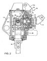
- Figure 2 is a partial cross-sectional view detail of the upper portion of the split tool tamper.
- Figure 3 is a partial cross-sectional top view of the split tool tamper.
- Figure 4 is a side view showing the split tool tamper attached to a frame.
- Figure 5 is a schematic top view of the split tool tamper with the eccentric hub in the twelve o'clock position.
- Figure 6 is a schematic top view of the split tool tamper with the eccentric hub in the three o'clock position.
- Figure 7 is a schematic top view of the split tool tamper with the eccentric hub in the nine o'clock position.
- As shown in Figure 1, the
split tool tamper 10 of the present invention includes amotor 11, such as a hydraulic motor, aconversion device 50, and asingle tool shaft 90. Thesplit tool tamper 10 may be pivotally attached to a generallyvertical frame 12. Theframe 12 may be attached to vertical translation means, such as a hydraulic piston 13 (Fig. 4). The vertical translation means may be coupled to a railroad car (not shown) or other suitable vehicle which may travel over a railroad ballast bed. Theconversion device 50 is enclosed with in ahousing 20. Thesplit tool tamper 10 further includes atool shaft 90 and atamping tool 100. Thetool shaft 90 is enclosed withinoutput shaft housing 91. - The
housing 20 may include alower mounting protrusion 14 and anupper mounting protrusion 24. As shown in Figs. 2-4,lower mounting protrusion 14 may be a pair oftabs tab Frame 12 includes a pair ofmounting tabs housing tabs pin end frame tab housing tab nut ends housing 20 toframe 12. - The
housing 20 is further connected toframe 12 atupper mounting protrusion 24.Upper mounting protrusion 24 may havetabs Frame 12 includes anupper frame tab 26 proximal to theupper mounting protrusion 24. Theupper frame tab 26 includes an opening therethrough. Anextension member 30, such as a hydraulic cylinder, extends betweenframe 12 andupper mounting protrusion 24. Theextension member 30 includes a first coupling end 31 andsecond coupling end 32. The coupling ends 31, 32 may have an opening for a pin. Theextension member 30 may be coupled toframe 12 by mountingpins 33, 34. As shown, mounting pin 33 is disposed through the opening in the first coupling end 31 andtab 26. Theother mounting pin 34 is disposed in thesecond coupling end 32 and openings 25a, 25b. Theextension member 30 has a first, closed position and a second, maximum extended position. Preferably, the split tool tamper may be angled 0 to 13 degrees from vertical by extending theextension member 30. In the first, closed position, extension member is structured to aligntool shaft 90 substantially parallel toframe 12. In the second, extended position,extension member 30 causeshousing 20 to rotate clockwise, as shown in Fig. 1, about mountingpins tool shaft 90 is angled downwardly and inwardly relative toframe 12. The extension member may be coupled to ahydraulic system 38 which can causeextension member 30 to move between the first and the second position approximately every three seconds. -
Motor 11 includes arotating output shaft 40 having a generally horizontal axis when theextension member 30 is in the first position.Rotating output shaft 40 is connected toconversion device 50. As is well known in the prior art,motor 11 rotatesoutput shaft 40 around the generally horizontal axis. Preferably, themotor 11 will rotateoutput shaft 40 at about 3000 R.P.M. As described below, themotor 11 in conjunction withconversion device 50 creates a reciprocating rotational motion intool shaft 90. - As shown in Figs. 1 and 2,
conversion device 50, which is connected to therotating output shaft 40, includes aneccentric hub 52 having a generally horizontal axis and an eccentric hub mounting means, such as a first roller bearing 54 and a second roller bearing 55. The eccentric hub mounting means extends betweenhousing 20 and outer bearing surface 70 (described below). Theeccentric hub 52 of theconversion device 50 is generally cup-shaped having adisk 56 with asidewall 57 extending from the perimeter of thedisk 56. Thesidewall 57 forms arecess 60 having an open face.Disk 56 is generally circular and includes amedial opening 62 therethrough so thatshaft 40 can pass through it.Sidewall 57 includes athick portion 64 and athin portion 66.Thick portion 64 is located on the opposite side ofdisk 56 fromthin portion 66.Sidewall 57 gradually decreases in thickness fromthick portion 64 tothin portion 66. The sidewall's 57 outer surface is anouter bearing surface 70. Thesidewall 57 also includes an inner wall which forms aninner bearing surface 71. - The
conversion device 50 further includes aspherical roller bearing 72.Spherical roller bearing 72 is a toroid having amedial opening 74 and anouter bearing surface 76.Roller bearing 72 is disposed within theeccentric hub recess 60. Roller bearingouter surface 76 contacts sidewallinner bearing surface 71.Spherical roller bearing 72 also includes aninner bearing surface 78. - The
conversion device 50 further includes ayoke 80 having ashaft 81, avertical cavity 82 and ahorizontal pin opening 83.Shaft 81 includes anouter bearing surface 86.Shaft 81 is disposed within roller bearingmedial hole 74 with bearingsurface 86 contacting roller bearinginner bearing surface 78. Anattachment pin 84 is disposed inhorizontal pin opening 83. -
Tool shaft 90 includes anupper end 92 and alower end 94.Upper end 92 forms a mounting bracket 96 having anopening 97 therethrough.Tool shaft opening 97 is sized to engageattachment pin 84. Shaftlower end 94 includes atamping tool 100. Thetamping tool 100 has alower end 101 that is structured to contact railroad ballast.Tool shaft 90 is supported inhousing 20 by two spacedbearings 98.Tool shaft 90 is supported bybearings 98 so thattool shaft 90 extends generally perpendicular torotating axle 40. - As noted above, the
split tool tamper 10 is pivotably mounted on aframe 12 by mountingpins frame 12 is coupled by a hydraulic piston to railroad vehicle (not shown) so that the axis of mountingpins extension member 30 is in the closed position, the axis ofrotating axle 40 extends in a direction generally normal to the axis of mountingpins eccentric hub 52, which is attached to rotatingaxle 40, androller bearing 72, which is disposed insideeccentric hub 52, also extend in a direction generally normal to the axis of mountingpins shaft 81 is disposed withinroller bearing 72, extending in a direction generally normal to the axis of mountingpins yoke 80 may be positioned so that the axis ofattachment pin 84 extends in a direction generally parallel to the axis of mountingpins conversion device 50 by passingattachment pin 84 throughhorizontal pin opening 83. When so configured, and whenextension member 30 is in the first position,tool shaft 90 extends in a generally vertical direction. The angle oftool shaft 90 may be changed by extendingextension member 30 to any point up to, and including, the maximum extended position ofextension member 30. As noted above, thesplit tool tamper 10, preferably, may be angled 0 to 13 degrees from vertical. - In operation,
motor 11 provides a rotational force to rotatingaxle 40. Rotatingaxle 40 rotateseccentric hub 52. Due to the eccentric shape ofeccentric hub 52, the axis ofeccentric hub 52 is reciprocated horizontally and vertically asaxle 40 is rotated.Roller bearing 72, which is disposed withineccentric hub 52, is thereby reciprocated horizontally and vertically. The reciprocal motion ofeccentric hub 52 is transferred from theroller bearing 72 to theshaft 81,yoke 80 andattachment pin 84, intotool shaft 90. The vertical position oftool shaft 90 is maintained bybearings 98. Thus,yoke 80 will pivot reciprocate in a vertical direction aboutpin 84. The horizontal reciprocation, however, is transferred totool shaft 90 as described below. - For the sake of this discussion the location of the eccentric hub sidewall
thick portion 64 will correlate to a clock's hour hand. Thus, when theeccentric hub 52 is described as being in the twelve o'clock position, sidewallthick portion 64 is in the upper most position. As shown in Fig. 5, theeccentric hub 52 is in the twelve o'clock position. When theeccentric hub 52 is in this position, the axis ofshaft 81 and the axis ofaxle 40, when seen from above, are aligned. As shown in Fig. 6, when theeccentric hub 52 is in the three o'clock position, the axis ofshaft 81, when seen from above, is offset approximately 2.5 degrees in a counter-clockwise direction from the axis ofaxle 40, as measured from the axis ofshaft 90. When the eccentric hub is in the 6:00 o'clock position (not shown) the axis ofshaft 81 and the axis ofaxle 40, when seen from above, are aligned. As shown in Fig. 7, when theeccentric hub 52 is in the nine o'clock position, the axis ofshaft 81, when seen from above, is offset approximately 2.5 degrees in a clockwise direction from the axis ofaxle 40, as measured from the axis ofshaft 90. Thus, rotation ofeccentric hub 52 results in a reciprocal rotational motion intool shaft 90. - While specific embodiments of the invention have been described in detail, it will be appreciated by those skilled in the art that various modifications and alternatives to those details could be developed in light of the overall teachings of the disclosure. For example, the motor may be a hydraulic, pneumatic or other type of motor. Accordingly, the particular arrangements disclosed are meant to be illustrative only and not limiting as to the scope of invention which is to be given the full breadth of the claims appended. As used in the appended claims, "coupled," means a linkage, direct or indirect, so long as a linkage occurs.
Claims (6)
- A split tool tamper (10) comprising:(a) a frame (12)(b) a motor (11) on said frame (12) for providing a generally reciprocating rotational motion:(c) tool shaft means (90) supported on said frame (12), said tool shaft means (90) being driven by said motor (11) to carry out said reciprocating rotational motion, said tool shaft means (90) having a first and a second end, said first end being coupled to said motor (11) by a conversion device (50) for converting the rotational motion of the motor (11) to an oscillating rotational motion;(d) tamping tool means (100) provided on said second end of said tool shaft means (90);
characterised in that(e) said tool shaft means (90) is a single tool shaft and said tamping tool means (100) is a single tamping tool, wherein the single tool shaft is adapted to drive a single tamping tool (100) on its second end; while(f) said motor (11) is, on the one hand, pivotally coupled to said frame (12) by a generally horizontal pivot (17a, 17b) and, on the other hand, by an extension member (30) attached to said motor (11) at a location spaced apart from said pivot (17a, 17b) so that said extension member (30) is able to pivot said single tool driving motor (11), said single tool shaft (90) and said single tamping tool (100) about said pivot (17a, 17b). - Split tool tamper according to claim 1, characterised in that said motor (11) includes a housing (91) and a rotating shaft (40), and said conversion device (50) includes:- an eccentric hub (52) having a medial opening (62) and a circular sidewall (57);- said hub sidewall (57) having an eccentric recess (60);- said motor shaft (40) passing through said medial opening (62) and being coupled to said hub (52);- a yoke (80) having a shaft (81) and a pivot pin (84);- said yoke shaft (81) being disposed in said hub eccentric recess (60);- a clevis (96) disposed at said first end of said tool shaft (81);- said clevis (96) being coupled to said yoke pivot pin (84); and- said single tool shaft (90) is supported by at least two bearings (98) in said housing (91).
- Split tool tamper according to claim 2, characterised in that said conversion device (50) also includes:- a spherical roller bearing (72) having a bearing surface (76) and a medial opening (74);- said spherical roller bearing disposed in said hub eccentric recess (60); and- said yoke shaft (81) is disposed in said spherical roller medial opening (74).
- Split tool tamper according to any of the preceding claims, characterised in that said single tool shaft (90) extends generally perpendicular to the rotating shaft (40) of said motor (11).
- Split tool tamper according to any of claims 2 to 4, characterised in that it further comprises a first roller bearing (54) disposed between said housing (20) and a bearing surface (70) of said eccentric hub (52), and/or a spherical roller bearing (72) and/or a spherical roller bearing (72) disposed between an outer bearing surface (86) of said yoke shaft (81) and an inner bearing surface (79) of said sidewall (57).
- Split tool tamper according to any of claims 2 to 5, characterised in that the axis of said pivot pin (84) extends generally perpendicular to the axis of said yoke shaft (81), and preferably generally perpendicular to the axis of said tool shaft means (90).
Priority Applications (1)
| Application Number | Priority Date | Filing Date | Title |
|---|---|---|---|
| EP06003299A EP1676958B1 (en) | 2000-07-12 | 2001-06-27 | Conversion device from rotational into oscillating motion |
Applications Claiming Priority (2)
| Application Number | Priority Date | Filing Date | Title |
|---|---|---|---|
| US614999 | 2000-07-12 | ||
| US09/614,999 US6386114B1 (en) | 2000-07-12 | 2000-07-12 | Single shaft tamper with reciprocating rotational output |
Related Child Applications (1)
| Application Number | Title | Priority Date | Filing Date |
|---|---|---|---|
| EP06003299A Division EP1676958B1 (en) | 2000-07-12 | 2001-06-27 | Conversion device from rotational into oscillating motion |
Publications (3)
| Publication Number | Publication Date |
|---|---|
| EP1172480A2 EP1172480A2 (en) | 2002-01-16 |
| EP1172480A3 EP1172480A3 (en) | 2003-07-16 |
| EP1172480B1 true EP1172480B1 (en) | 2007-01-10 |
Family
ID=24463575
Family Applications (2)
| Application Number | Title | Priority Date | Filing Date |
|---|---|---|---|
| EP01115430A Expired - Lifetime EP1172480B1 (en) | 2000-07-12 | 2001-06-27 | Split tool tamper |
| EP06003299A Expired - Lifetime EP1676958B1 (en) | 2000-07-12 | 2001-06-27 | Conversion device from rotational into oscillating motion |
Family Applications After (1)
| Application Number | Title | Priority Date | Filing Date |
|---|---|---|---|
| EP06003299A Expired - Lifetime EP1676958B1 (en) | 2000-07-12 | 2001-06-27 | Conversion device from rotational into oscillating motion |
Country Status (5)
| Country | Link |
|---|---|
| US (1) | US6386114B1 (en) |
| EP (2) | EP1172480B1 (en) |
| DE (2) | DE60135040D1 (en) |
| ES (1) | ES2307243T3 (en) |
| PT (1) | PT1676958E (en) |
Cited By (1)
| Publication number | Priority date | Publication date | Assignee | Title |
|---|---|---|---|---|
| AU2003203686B2 (en) * | 2002-04-12 | 2009-09-17 | Harsco Technologies Corporation | Conversion device for converting a rotational motion into a reciprocal motion |
Families Citing this family (12)
| Publication number | Priority date | Publication date | Assignee | Title |
|---|---|---|---|---|
| US6978718B2 (en) * | 2004-03-04 | 2005-12-27 | Seyrlehner Georg J | Tamping device and method of tamping a railroad track's ballast |
| RU2337201C1 (en) * | 2007-07-10 | 2008-10-27 | Государственное образовательное учреждение высшего профессионального образования "Петербургский государственный университет путей сообщения" | Electric tie tamper |
| CN103015275B (en) * | 2011-09-28 | 2016-01-20 | 安阳振动器有限责任公司 | Portable tamping pickaxe |
| US9731324B2 (en) * | 2013-09-25 | 2017-08-15 | Nordco Inc. | Drive for railroad ballast tamper apparatus |
| CN104846705A (en) * | 2015-04-29 | 2015-08-19 | 柳州三农科技有限公司 | Application method of electric flexible shaft tamper |
| USD789994S1 (en) | 2015-08-05 | 2017-06-20 | Nordco Inc. | Tamper tool |
| AU2016204901A1 (en) * | 2015-08-10 | 2017-03-02 | Nordco Inc. | Tamper Tool and Associated Holder |
| EP3356601B1 (en) * | 2015-10-01 | 2022-07-27 | Harsco Technologies LLC | Method of operating a tamping machine and system therefore |
| AT517999B1 (en) | 2015-11-20 | 2018-05-15 | Plasser & Theurer Export Von Bahnbaumaschinen Gmbh | Stopfaggregat and method for plugging a track |
| AT520267B1 (en) * | 2017-08-08 | 2020-02-15 | Plasser & Theurer Export Von Bahnbaumaschinen Gmbh | Tamping unit for tamping sleepers on a track |
| AT523825B1 (en) * | 2020-07-03 | 2021-12-15 | Plasser & Theurer Export Von Bahnbaumaschinen Gmbh | Machine and method with a tamping unit |
| CN116791895B (en) * | 2022-04-29 | 2025-08-19 | 中国电建集团华东勘测设计研究院有限公司 | Basement bearing platform concrete layered pouring and vibrating device and application method thereof |
Family Cites Families (19)
| Publication number | Priority date | Publication date | Assignee | Title |
|---|---|---|---|---|
| US2201023A (en) * | 1940-05-14 | Railroad tie tamping machine | ||
| US798416A (en) * | 1904-02-15 | 1905-08-29 | Jackson Electric Drill And Supply Company | Rock-drill. |
| US1464570A (en) * | 1920-05-17 | 1923-08-14 | Hage Rudolf Alexander | Riveting, chiseling, and rock-drilling hammer |
| US1399387A (en) * | 1921-04-11 | 1921-12-06 | Jackson Corwill | Tamper and like impact-tool |
| US1621103A (en) * | 1926-01-20 | 1927-03-15 | Ajax Electric Hammer Corp | Power-driven hammer or riveter |
| US1932723A (en) * | 1928-09-04 | 1933-10-31 | Hugh S Brown | Vibratory tool |
| US2079909A (en) * | 1934-09-26 | 1937-05-11 | Jackson Corwill | Vibrating motor |
| AT236434B (en) * | 1961-08-16 | 1964-10-26 | Plasser Bahnbaumasch Franz | Track tamping machine |
| AT315227B (en) * | 1969-08-08 | 1974-05-10 | Plasser Bahnbaumasch Franz | Tamping tool for track tamping machines |
| US3736879A (en) * | 1971-05-13 | 1973-06-05 | Jackson Vibrators | Ballast tamper blade |
| DE2236371C2 (en) * | 1972-07-25 | 1977-02-24 | Losenhansen Maschinenbau Ag | HAND-HELD TAMPER |
| US3901159A (en) * | 1974-03-21 | 1975-08-26 | Canron Inc | Tamping tool head |
| DE2441180C3 (en) * | 1974-08-28 | 1981-06-11 | Koehring Gmbh - Bomag Division, 5407 Boppard | Hand-operated vibratory tamper |
| AT343168B (en) | 1976-02-20 | 1978-05-10 | Plasser Bahnbaumasch Franz | TRACKING MACHINE WITH AT LEAST ONE HIGHLY ADJUSTABLE STOPPING UNIT |
| AT350097B (en) * | 1977-02-04 | 1979-05-10 | Plasser Bahnbaumasch Franz | MACHINE FOR PLUGGING THE SLEEPERS OF A TRACK |
| PL163768B1 (en) | 1989-04-18 | 1994-05-31 | Plasser Bahnbaumasch Franz | Mobile machine for tamping a railway track |
| US5363711A (en) * | 1991-04-22 | 1994-11-15 | Osada Research Institute, Ltd. | Power transmission device |
| ES2088659T3 (en) | 1992-08-12 | 1996-08-16 | Plasser Bahnbaumasch Franz | RAILWAY BATTERING MACHINE FOR THE INTERRUPTING OF CHANGES AND CROSSINGS OF A WAY. |
| ES2101605T3 (en) * | 1994-08-09 | 1997-07-01 | Plasser Bahnbaumasch Franz | BATING GROUP FOR RAILWAY BATTERING MACHINES, FOR THE INTERRUPTING OF TWO CROSSBANDS IMMEDIATELY CONTIGUOUS. |
-
2000
- 2000-07-12 US US09/614,999 patent/US6386114B1/en not_active Expired - Lifetime
-
2001
- 2001-06-27 EP EP01115430A patent/EP1172480B1/en not_active Expired - Lifetime
- 2001-06-27 EP EP06003299A patent/EP1676958B1/en not_active Expired - Lifetime
- 2001-06-27 ES ES06003299T patent/ES2307243T3/en not_active Expired - Lifetime
- 2001-06-27 DE DE60135040T patent/DE60135040D1/en not_active Expired - Lifetime
- 2001-06-27 PT PT06003299T patent/PT1676958E/en unknown
- 2001-06-27 DE DE60125871T patent/DE60125871T2/en not_active Expired - Lifetime
Cited By (1)
| Publication number | Priority date | Publication date | Assignee | Title |
|---|---|---|---|---|
| AU2003203686B2 (en) * | 2002-04-12 | 2009-09-17 | Harsco Technologies Corporation | Conversion device for converting a rotational motion into a reciprocal motion |
Also Published As
| Publication number | Publication date |
|---|---|
| EP1676958A1 (en) | 2006-07-05 |
| US6386114B1 (en) | 2002-05-14 |
| PT1676958E (en) | 2008-08-06 |
| DE60135040D1 (en) | 2008-09-04 |
| DE60125871D1 (en) | 2007-02-22 |
| DE60125871T2 (en) | 2007-04-19 |
| ES2307243T3 (en) | 2008-11-16 |
| EP1676958B1 (en) | 2008-07-23 |
| EP1172480A2 (en) | 2002-01-16 |
| EP1172480A3 (en) | 2003-07-16 |
Similar Documents
| Publication | Publication Date | Title |
|---|---|---|
| EP1676958B1 (en) | Conversion device from rotational into oscillating motion | |
| WO1999005363A1 (en) | Vibratory pavement breaker | |
| US4963224A (en) | Motorized carpet and tile stripping tool | |
| US6581524B1 (en) | Conversion device for converting a rotational motion into a reciprocal motion | |
| CN114179855A (en) | Novel adjustable contact seat of monorail train goat stroke | |
| ID19837A (en) | GRINDER | |
| CA2237012A1 (en) | Independent brake handle assembly | |
| CN1214391A (en) | Tamping unit | |
| JPH11313503A (en) | Levee reshaping machine | |
| EP1134883A3 (en) | Vibration motors | |
| CN218786746U (en) | Steel rail grinding stone installation and pressing device | |
| RU2048631C1 (en) | Tie-tamper unit of track maintenance machine | |
| CN214116242U (en) | Highway bridge road crusher | |
| KR100426522B1 (en) | Rail way line divergence device | |
| JP3895701B2 (en) | Escape crank for railway turnout | |
| CN210657823U (en) | Tamping device with eccentric clamping mechanism | |
| CN210127368U (en) | Tamping device with contact maintaining mechanism | |
| CN113562015A (en) | Stone sweeper | |
| CN220013482U (en) | Rotary gate movement | |
| KR200169886Y1 (en) | Operating apparatus for a compressor | |
| CN221877570U (en) | Vibrating frame of hydraulic tamping machine | |
| CN208127052U (en) | A kind of flame-proof switch isolation propulsion device | |
| JPH08184524A (en) | Vehicle vibration device | |
| CN202705870U (en) | Compaction beam for screed plate, screed plate and paving machine | |
| CN2033015U (en) | Four connecting rod swing joint vibrating rammer |
Legal Events
| Date | Code | Title | Description |
|---|---|---|---|
| PUAI | Public reference made under article 153(3) epc to a published international application that has entered the european phase |
Free format text: ORIGINAL CODE: 0009012 |
|
| AK | Designated contracting states |
Kind code of ref document: A2 Designated state(s): AT BE CH CY DE DK ES FI FR GB GR IE IT LI LU MC NL PT SE TR |
|
| AX | Request for extension of the european patent |
Free format text: AL;LT;LV;MK;RO;SI |
|
| PUAL | Search report despatched |
Free format text: ORIGINAL CODE: 0009013 |
|
| AK | Designated contracting states |
Designated state(s): AT BE CH CY DE DK ES FI FR GB GR IE IT LI LU MC NL PT SE TR |
|
| AX | Request for extension of the european patent |
Extension state: AL LT LV MK RO SI |
|
| 17P | Request for examination filed |
Effective date: 20031016 |
|
| 17Q | First examination report despatched |
Effective date: 20031117 |
|
| AKX | Designation fees paid |
Designated state(s): DE ES GB IT PT |
|
| GRAP | Despatch of communication of intention to grant a patent |
Free format text: ORIGINAL CODE: EPIDOSNIGR1 |
|
| GRAS | Grant fee paid |
Free format text: ORIGINAL CODE: EPIDOSNIGR3 |
|
| RAP1 | Party data changed (applicant data changed or rights of an application transferred) |
Owner name: HARSCO CORPORATION |
|
| GRAA | (expected) grant |
Free format text: ORIGINAL CODE: 0009210 |
|
| AK | Designated contracting states |
Kind code of ref document: B1 Designated state(s): DE ES GB IT PT |
|
| REG | Reference to a national code |
Ref country code: GB Ref legal event code: FG4D |
|
| REF | Corresponds to: |
Ref document number: 60125871 Country of ref document: DE Date of ref document: 20070222 Kind code of ref document: P |
|
| PG25 | Lapsed in a contracting state [announced via postgrant information from national office to epo] |
Ref country code: ES Free format text: LAPSE BECAUSE OF FAILURE TO SUBMIT A TRANSLATION OF THE DESCRIPTION OR TO PAY THE FEE WITHIN THE PRESCRIBED TIME-LIMIT Effective date: 20070421 |
|
| PG25 | Lapsed in a contracting state [announced via postgrant information from national office to epo] |
Ref country code: PT Free format text: LAPSE BECAUSE OF FAILURE TO SUBMIT A TRANSLATION OF THE DESCRIPTION OR TO PAY THE FEE WITHIN THE PRESCRIBED TIME-LIMIT Effective date: 20070611 |
|
| PLBE | No opposition filed within time limit |
Free format text: ORIGINAL CODE: 0009261 |
|
| STAA | Information on the status of an ep patent application or granted ep patent |
Free format text: STATUS: NO OPPOSITION FILED WITHIN TIME LIMIT |
|
| 26N | No opposition filed |
Effective date: 20071011 |
|
| PG25 | Lapsed in a contracting state [announced via postgrant information from national office to epo] |
Ref country code: IT Free format text: LAPSE BECAUSE OF NON-PAYMENT OF DUE FEES Effective date: 20090627 |
|
| PGRI | Patent reinstated in contracting state [announced from national office to epo] |
Ref country code: IT Effective date: 20110616 |
|
| REG | Reference to a national code |
Ref country code: DE Ref legal event code: R082 Ref document number: 60125871 Country of ref document: DE Representative=s name: MURGITROYD & COMPANY, DE |
|
| PGFP | Annual fee paid to national office [announced via postgrant information from national office to epo] |
Ref country code: DE Payment date: 20200629 Year of fee payment: 20 |
|
| PGFP | Annual fee paid to national office [announced via postgrant information from national office to epo] |
Ref country code: IT Payment date: 20200619 Year of fee payment: 20 Ref country code: GB Payment date: 20200629 Year of fee payment: 20 |
|
| REG | Reference to a national code |
Ref country code: DE Ref legal event code: R071 Ref document number: 60125871 Country of ref document: DE |
|
| REG | Reference to a national code |
Ref country code: GB Ref legal event code: PE20 Expiry date: 20210626 |
|
| PG25 | Lapsed in a contracting state [announced via postgrant information from national office to epo] |
Ref country code: GB Free format text: LAPSE BECAUSE OF EXPIRATION OF PROTECTION Effective date: 20210626 |