EP1172288A1 - Fixing structure between links and pins in crawler - Google Patents
Fixing structure between links and pins in crawler Download PDFInfo
- Publication number
- EP1172288A1 EP1172288A1 EP00979971A EP00979971A EP1172288A1 EP 1172288 A1 EP1172288 A1 EP 1172288A1 EP 00979971 A EP00979971 A EP 00979971A EP 00979971 A EP00979971 A EP 00979971A EP 1172288 A1 EP1172288 A1 EP 1172288A1
- Authority
- EP
- European Patent Office
- Prior art keywords
- pin
- link
- retaining ring
- pressure receiving
- receiving surface
- Prior art date
- Legal status (The legal status is an assumption and is not a legal conclusion. Google has not performed a legal analysis and makes no representation as to the accuracy of the status listed.)
- Granted
Links
- 238000003825 pressing Methods 0.000 claims abstract description 59
- 238000003780 insertion Methods 0.000 claims abstract description 34
- 230000037431 insertion Effects 0.000 claims abstract description 34
- 230000003247 decreasing effect Effects 0.000 claims abstract description 7
- 238000003754 machining Methods 0.000 abstract description 12
- 238000004519 manufacturing process Methods 0.000 description 9
- 230000008901 benefit Effects 0.000 description 4
- 239000002184 metal Substances 0.000 description 4
- 238000003892 spreading Methods 0.000 description 4
- 230000007480 spreading Effects 0.000 description 4
- 230000000694 effects Effects 0.000 description 3
- 238000010276 construction Methods 0.000 description 2
- 239000010687 lubricating oil Substances 0.000 description 2
- 239000000463 material Substances 0.000 description 2
- 230000007246 mechanism Effects 0.000 description 2
- 230000008439 repair process Effects 0.000 description 2
- 238000005461 lubrication Methods 0.000 description 1
Images



Classifications
-
- B—PERFORMING OPERATIONS; TRANSPORTING
- B62—LAND VEHICLES FOR TRAVELLING OTHERWISE THAN ON RAILS
- B62D—MOTOR VEHICLES; TRAILERS
- B62D55/00—Endless track vehicles
- B62D55/08—Endless track units; Parts thereof
- B62D55/18—Tracks
- B62D55/20—Tracks of articulated type, e.g. chains
- B62D55/205—Connections between track links
- B62D55/21—Links connected by transverse pivot pins
-
- B—PERFORMING OPERATIONS; TRANSPORTING
- B60—VEHICLES IN GENERAL
- B60Y—INDEXING SCHEME RELATING TO ASPECTS CROSS-CUTTING VEHICLE TECHNOLOGY
- B60Y2200/00—Type of vehicle
- B60Y2200/20—Off-Road Vehicles
- B60Y2200/25—Track vehicles
-
- F—MECHANICAL ENGINEERING; LIGHTING; HEATING; WEAPONS; BLASTING
- F16—ENGINEERING ELEMENTS AND UNITS; GENERAL MEASURES FOR PRODUCING AND MAINTAINING EFFECTIVE FUNCTIONING OF MACHINES OR INSTALLATIONS; THERMAL INSULATION IN GENERAL
- F16B—DEVICES FOR FASTENING OR SECURING CONSTRUCTIONAL ELEMENTS OR MACHINE PARTS TOGETHER, e.g. NAILS, BOLTS, CIRCLIPS, CLAMPS, CLIPS OR WEDGES; JOINTS OR JOINTING
- F16B21/00—Means for preventing relative axial movement of a pin, spigot, shaft or the like and a member surrounding it; Stud-and-socket releasable fastenings
- F16B21/10—Means for preventing relative axial movement of a pin, spigot, shaft or the like and a member surrounding it; Stud-and-socket releasable fastenings by separate parts
Definitions
- the present invention relates to a fastening structure between a link and a pin of a crawler belt in a vehicle such as a construction machine.
- a crawler belt utilized in a construction machine such as a bulldozer and a hydraulic shoveling machine, comprises an endless annular link chain provided with shoes (crawler shoes) for contact with ground.
- the link chain has such a structure that a plurality of links are interconnected by pins.
- a structure of the link interconnection is shown in Fig. 8.
- the link chain includes a predetermined number of link pairs of a left-hand and a right-hand links 31, 32 disposed in a longitudinal direction.
- a pin 33 and a bushing 34 fasten an end portion of a longitudinally preceding link pair to a front portion of the following link pair.
- the pin 33 is inserted into the bushing 34, and the bushing 34 is press-fitted into rear holes 41a, 42a of the preceding links 31a, 32a, whereas the pin 33 is press-fitted into front holes 41b, 42b of the following links 31b, 32b. Since the bushing 34 and the pin 33 are pivotable, the preceding and the following links 31a, 31b are connected with each other in a bendable manner like a joint. It should be noted here that, in Fig. 8, a portion indicated by numeral 35 is a lubricating oil supplying hole. Lubricating oil supplied here provides lubrication between the pin 33 and the bushing 34.
- the pin 33 is subjected to a large force in a direction of thrust during use. Therefore, according to the link chain described as above, a retaining mechanism for preventing the pin 33 from coming out of the links 31, 32 is provided (for example, U.S. Patent Publication No. 4618190).
- a retaining mechanism for preventing the pin 33 from coming out of the links 31, 32 is provided (for example, U.S. Patent Publication No. 4618190).
- an annular recess is formed around an opening of the pin insertion hole in the link. Further, close to an end portion of the pin, a circumferential groove smoothly recessing in an axially inward direction is formed.
- the recess in the link and the groove in the pin form a cavity having an annular opening, between the circumferential edge of the opening of the pin insertion hole and the outer end portion of the pin.
- an annular retainer made of a metal for preventing the pin from coming out.
- the retainer is plastically deformed to conform to the shape of the cavity, so as to fill the cavity with the retainer, thereby preventing the pin from relative, disengaging movement out of the link toward the side away from the opening.
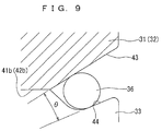
- the Japanese Patent Application No. Hei 11-182264 proposes a fastening structure of link and pin, in which a retaining ring 36 is employed.
- a retaining ring 36 is employed.
- an annular space 45 is formed between a circumferential edge of an opening of pin insertion holes 41b, 42b of the links 31, 32 and a corresponding end portion of a pin 33.
- the retaining ring 36 is disposed in this space 45, thereby preventing the relative, disengaging movement of the pin 33 toward the side away from the opening.
- the pin 33 is formed with a tapered outer surface 44 facing the tapered inner surface 43.
- a slanting angle of the tapered outer surface 44, with respect to the axis, is slightly smaller than a slanting angle of the tapered inner surface 7. With this arrangement, the tapered surfaces 43, 44 are farther away from each other in the outward direction.
- the retaining ring 36 is made of an annular elastic metal having a circular section, with a part of the ring cut out so that the ring can elastically spread and shrink in diameter.
- the above described fastening structure between link and pin of a crawler belt has the following problems resulting from that the opening portion of the pin insertion hole 41b of the link 31 and the outer end portion of the pin 33 are tapered surfaces 43, 44 respectively, and that the retaining ring 36 has a circular section.
- first, assembling operation is costly. More specifically, since the section of the retaining ring 36 is circular, the ring circumferential surface cannot have a sufficient area of contact with each of the tapered surfaces 43, 44, being unable to obtain sufficient initial friction from the elastic restoring force of the retaining ring 36 alone. For this reason, in an assembling step, an operation of driving the retaining ring 36 inwardly is necessary.
- the tapered inner surface 43 and the tapered outer surface 44 have to be machined to a high accuracy. Specifically, if the angle made by the two tapered surfaces 43, 44 is too large, the retaining ring 36 cannot be held by the friction and moves away, becoming unable to provide the expected function. For example, in the state shown in Fig. 9, it has been confirmed that the angle ⁇ between the tapered surfaces 43, 44 must be smaller than 20° approximately. As a result of such a high machining accuracy required of each part, manufacturing cost of these has to increase.
- the present invention is made to solve the above described problems, with an object to provide a fastening structure between link and pin of a crawler belt which can be assembled by simple operation at a low cost, without requiring a high machining accuracy, and thus can be manufactured at a low cost.
- a fastening structure of link and pin of a crawler belt is a fastening structure of a link and a pin in a crawler belt of a vehicle.
- An annular space 15 is formed between a circumferential edge of an opening of a pin insertion hole 5 of a link 2 and an outer end portion of a pin 1 to be inserted in the pin insertion hole 5, and a retaining ring 3 is disposed in the space 15 whereby preventing relative, disengaging movement of the pin 1 toward a side away from the opening.
- the structure is characterized in that one of the circumferential edge of the opening of the pin insertion hole 5 of the link 2 and the outer end portion of the pin 1 is formed with a tapered pressure receiving surface 8 having a diameter gradually decreasing in an axially inward direction, the other is formed with a pressing portion 7, and the retaining ring 3 is formed with a friction surface 9 to be press-contacted to the pressure receiving surface 8 by a force from the pressing portion 7 upon development of the relative movement in the disengaging direction.
- the pressing portion 7 may be an edge portion as in the first embodiment through the third embodiment, or may be a tapered pressure receiving surface as in the fourth embodiment. In this case, a portion of the retaining ring 3 contacted by the pressing portion 7, (a pressed surface), is formed as a friction surface as in the fourth embodiment.
- the fastening structure between link and pin of a crawler belt provided by the first invention, the following function is performed.
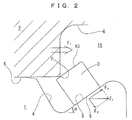
- the pin 1 makes a relative movement in the disengaging direction toward the side away from the opening, then the pressing portion 7 of the link 2 contacts the pressed surface 10 of the retaining ring 3, and the friction surface 9 of the retaining ring 3 press-contacts the tapered, pressure receiving surface 8.
- the ring 3 is under a force acting in the disengaging direction.
- This force F 1 can be divided into a component force F 2 acting vertically to the pressure receiving surface 8 and another component force F 3 acting along the pressure receiving surface 8.
- the relative, disengaging movement toward the side away from the opening is prevented by selecting a condition that makes friction generated by the component force F 2 acting vertically to the pressure receiving surface 8 greater than the component force F 3 acting along the pressure receiving surface 8.
- the pressure receiving surface 8 slanted axially inward is given a slant angle ⁇ that satisfies the above mentioned relationship ⁇ F 2 >F 3 (where ⁇ represents friction coefficient), thereby preventing the pin from relative, disengaging movement out of the link toward the side away from the opening.
- the retaining ring 3 contacts the pressure receiving surface 8 via its friction surface 9. For this reason, the retaining ring 3 has a greater area of contact with the pressure receiving surface 8 than in the prior art. Therefore, elastic restoring force of the retaining ring 3 alone can generate sufficient initial friction. Thus, there no longer is the need for the operation of inwardly driving the retaining ring 3 during the assembly. As a result, there no longer is the need for the special jig and the pressing apparatus for driving the ring 3, and as a result, it becomes possible to reduce cost necessary for the assembling operation.
- the slant angle ⁇ of the pressure receiving surface 8 slanting axially inward should only satisfy the above mentioned relationship ⁇ F 2 >F 3 .
- a fastening structure between link and pin of a crawler belt according to a second invention is characterized in that the retaining ring 3 includes a pressed surface 10 contacted by the pressing portion 7, and the friction surface 9, whereas the pressed surface 10 and the friction surface 9 are farther away from each other in an outward direction.
- the friction surface 9 and the pressed surface 10 of the retaining ring 3 are farther away from each other in the outward direction. Therefore, even if there is inconsistency in an engaging dimension between the pressing portion 7 and the pressure receiving surface 8 resulting from machining error, assembling error and so on, the friction surface 9 and the pressed surface 10 of the retaining ring 3 can make respective engagements at various dimensions, which means an engageable range for the two is increased. As a result, it becomes possible to allow for more generous tolerance in the shape and dimensions of the pressing portion 7 in the link 2 and of the pressure receiving surface 8 in the pin 1 than in the prior art.
- a fastening structure between link and pin of a crawler belt according to a third invention is characterized in that the retaining ring 3 has a square section.
- the retaining ring 3 since the retaining ring 3 has a square section, manufacture thereof becomes easy, and can be embodied at a low cost.
- a fastening structure between link and pin of a crawler belt according to a fourth invention is characterized in that the pressing portion 7 is formed like an edge.
- the fastening structure between link and pin of a crawler belt provided by the fourth invention, by making one of the circumferential edge of the opening of the pin insertion hole 5 of the link 2 and the outer end portion of the pin 1 as the edge-like pressing portion 7, it becomes possible to allow for even more generous tolerance in the shape and dimensions of the pressing portion 7 in the link 2 and of the pressure receiving surface 8 in the pin 1 than in the case where both are made as tapered pressure receiving surfaces.
- a fastening structure between link and pin of a crawler belt according to a fifth invention is a fastening structure of a link and a pin in a crawler belt of a vehicle.
- An annular space 15 is formed between a circumferential edge of an opening of a pin insertion hole 5 of a link 2 and an outer end portion of a pin 1 inserted in the pin insertion hole 5, and a retaining ring 3 is disposed in the space 15 whereby preventing relative disengaging movement of the pin 1 toward a side away from the opening.
- the structure is characterized in that one of the circumferential edge of the opening of the pin insertion hole 5 of the link 2 and the end portion of the pin 1 is formed with a tapered pressure receiving surface 8 having a diameter gradually decreasing in an axially inward direction, the other is formed with an edge-like pressing portion 7, and the retaining ring 3 press-contacts each of the pressing portion 7 and the pressure receiving surface 8.
- the fastening structure between link and pin of a crawler belt provided by the fifth invention, the following function is performed.
- the pressure receiving surface 8 slanted axially inward is given a slant angle ⁇ that satisfies the above mentioned relationship ⁇ F 2 >F 3 (where ⁇ represents friction coefficient), thereby preventing the pin from relative, disengaging movement out of the link toward the side away from the opening.
- the retaining ring 3 has the friction surface 9 provided by the assemblage, making contact with the pressure receiving surface 8. Therefore, the retaining ring 3 has a greater area of contact with the pressure receiving surface 8 than in the prior art, making possible to obtain sufficient initial friction. Further, since one of the circumferential edge of the opening of the pin insertion hole 5 of the link 2 and the outer end portion of the pin 1 is made into the edge-like pressing portion 7, the retaining ring 3 receives the pressure at a point, and thus it becomes possible to perform the assembling operation more easily, using less pressing force than in the case where the two members are each formed with a tapered surface, i.e. than in the case where the pressure is received on a surface. As a result, operating efficiency in the assembling operation can be improved.
- the slant angle ⁇ of the pressure receiving surface 8 slanting axially inward should only satisfy the above mentioned relationship ⁇ F 2 >F 3 .
- a fastening structure between link and pin of a crawler belt according to a sixth invention is characterized in that the retaining ring 3 has a circular section.
- the retaining ring 3 has a circular section, manufacture thereof becomes easy, making possible to embody at a low cost.
- the pin 1 has an end, close to which a circumferential groove 4 having a generally triangular section is formed.
- the link 2 is formed with a pin insertion hole 5 into which the pin 1 is press-fitted.
- the pin insertion hole 5 has an opening, around which an annular recess 6 is formed.
- the groove 4 of the pin 1 and the recess 6 of the pin insertion hole 5 form an annular fitting space 15 recessing axially inward and having an annular opening, between a circumferential edge of the opening of the pin insertion hole 5 and the outer end portion of the pin 1.
- the recess 6 meets an edge of the opening of the pin insertion hole 5. This edge serves as a pressing portion 7, function of which will be described later.
- the groove 4 of the pin 1 includes a tapered outer surface 8 facing the pressing portion 7.
- the tapered outer surface 8 gradually shrinks in diameter axially inwardly, and as will be described later, serves as a pressure receiving surface.
- the retaining ring 3 is made of an annular elastic metal, with a part of the ring cut out so that the ring can elastically spread and shrink in diameter. Further, the retaining ring 3 has a generally square section, with one corner of the square being in an inner diameter region (the lower side as in the figure) and another corner being in an outer diameter region (the upper side as in the figure).
- assembling operation can be completed by simply press-fitting the pin 1 into the pin insertion hole 5 of the link 2, then spreading and disposing the retaining ring 3 into the groove 4 of the pin 1, and finally removing the spreading force thereby allowing the retaining ring 3 to elastically shrink in diameter.
- the retaining ring 3 has its inner diameter side contacting the tapered outer surface 8 whereas the outer diameter side has its inner side surface contacting the pressing portion 7.
- the surface contacting the tapered outer surface 8 i.e. the outer side surface on the inner diameter side
- the surface contacting the pressing portion 7 i.e. the inner side surface on the outer diameter side
- the link 2 tends to move out of the pin 1, the following function prevents the disengaging movement. Specifically, first, if the link 2 tends to move rightward as in Fig. 1 (i.e. if the pin 1 tends to make a relative movement in a disengaging direction toward the side away from the opening), then the pressing portion 7 of the link 2 presses the pressed surface 10 of the retaining ring 3, twisting the retaining ring 3 outward as shown in Fig. 2, thereby making the friction surface 9 of the retaining ring 3 contact the tapered outer surface, i.e. the pressure receiving surface 8. Under this state, the ring 3 is under a force acting in the disengaging direction (to the right as in the figure).
- This force F 1 can be divided into a component force F 2 acting vertically to the pressure receiving surface 8 and another component force F 3 acting along the pressure receiving 8. If the friction generated by the component force F 2 acting vertically to the pressure receiving surface 8 is greater than the component force F 3 acting along the pressure receiving surface 8, then the relative, disengaging movement of the pin 1 toward the side away from the opening is prevented.
- the pressure receiving surface 8 slanted axially inward is given a slant angle ⁇ that satisfies the above mentioned relationship ⁇ F 2 >F 3 (where ⁇ represents friction coefficient).
- the retaining ring 3 contacts the pressure receiving surface 8 via its friction surface 9. For this reason, the retaining ring 3 has a greater area of contact with the pressure receiving surface 8 than in the prior art. Therefore, elastic restoring force of the retaining ring 3 alone can generate sufficient initial friction. Thus, there no longer is the need for the operation of inwardly driving the retaining ring 3 during the assembly. As a result, there no longer is the need for the specialized jig and the pressing apparatus for driving the retaining ring 3, and as a result, it becomes possible to reduce cost necessary for the assembling operation.
- the shape of the pressing portion 7 and the pressure receiving surface 8, and material characteristic of the retaining ring 3 are so selected that even if the pin 1 and the link 2 are disassembled for a purpose of repair and so on, the retaining ring 3 can be reused since the retaining ring 3 is only elastically deformed at the time of the assembly.
- the slant angle ⁇ of the pressure receiving surface 8 slanting axially inward should only satisfy the above mentioned relationship ⁇ F 2 >F 3 .
- the edge-like pressing portion 7 provided in the line 2 makes possible to allow for more generous tolerance in the shape and dimensions of the pressing portion 7 in the link 2 and of the pressure receiving surface 8 in the pin 1 than in the case where both are made as tapered pressure receiving surfaces.
- the tapered surface 44 must be formed also in the link 2.
- the link 2 since the link 2 has a non-circular outer shape, it is very difficult to form a tapered annular surface 44 in such an object as the link 2.
- the link 2 should only be formed with the pressing portion 7, and there is no need for forming the tapered surface. This leads to an advantage of simplified machining operation.
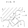
- Fig. 3 shows a second embodiment, in which the retaining ring 3 has a square section like the embodiment shown in Fig. 1.
- the shape of a vicinity of the pressing portion 7 in the link 2 changed.
- a tapered guide surface 11 having a diameter decreasing in an axially inward direction is formed on an outward side of the pressing portion 7.
- the guide surface 11 allows the pressed surface 10 of the retaining ring 3 to reliably contact the pressing portion 7, thereby making easy the assembling operation of the retaining ring 3.
- the same function and effect as achieved in the first embodiment can be obtained.
- Fig. 4 shows a third embodiment, in which the retaining ring 3 has a different shape in section.
- the section is not square as in the embodiments in Fig. 1 and Fig. 2 (in which the friction surface 9 and the pressed surface 10 are parallel to each other).
- the friction surface 9 and the pressing surface 10 are each tapered to have an outwardly increasing diameter, and further, a distance between the two surfaces increases in the outward direction.
- the retaining ring 3 is given a laterally mirror symmetric section in the figure, so that the ring can be used also at the other end portion of the pin 1.
- the friction surface 9 and the pressed surface 10 of the retaining ring 3 are not limited in a certain fixed engaging dimension, and therefore can make respective engagements at various dimensions. This means an engagable range for the two surfaces is increased.
- Fig. 6 shows a fourth embodiment.
- the retaining ring 3 has the same sectional shape as in Fig. 4 and Fig. 5, whereas the pressing portion 7 of the link 2 is made as a tapered, pressure receiving surface having a diameter gradually decreasing in an axially inward direction.
- a pin insertion hole 5 also is formed with a pressure receiving surface 7 around the opening, in addition to the pressure receiving surface 8 formed at the outer end portion of the pin 1.
- a distance between the pressure receiving surfaces 7, 8 gradually increases outwardly.
- a pressed surface 10 of the retaining ring 3 serves as a friction surface, i.e. both of the friction surfaces 9, 10 make contact with the pressure receiving surfaces 7, 8 respectively.
- Fig. 7A and Fig. 7B show a fifth embodiment, in which the retaining ring 3 is made to have a circular section.
- the pin 1 has an end, close to which a circumferential groove 4 having a generally triangular section is formed.
- the link 2 is formed with a pin insertion hole 5 into which the pin 1 is press-fitted.
- the pin insertion hole 5 has an opening, around which an annular recess 6 is formed.
- the groove 4 of the pin 1 and the recess 6 of the pin insertion hole 5 form an annular fitting space 15 recessing axially inward and having an annular opening, between a circumferential edge of the opening of the pin insertion hole 5 and the outer end portion of the pin 1. Further, an edge-like pressing portion 7 is formed at a location where the recess 6 meets the opening of the pin insertion hole 5, further outward of which, starting from the pressing portion 7 in an outward direction, there is formed an axially slanted, tapered guide surface 11 gradually increasing in diameter.
- the groove 4 of the pin 1 has a tapered outer surface 8 facing the pressing portion 7.
- the tapered outer surface 8 gradually increases in diameter in the axially outward direction, and as will be described later, serves as a pressure receiving surface.
- the tapered outer surface (hereinafter called a pressure receiving surface 8) has a slanting angle, slanting with respect to the axis, smaller than a slanting angle of the guide surface 11.
- the retaining ring 3 is made of an annular elastic metal, with a part of the ring cut out so that the ring can elastically spread and shrink in diameter. Further, the retaining ring 3 has a generally circular section, being press-contacted to the pressing portion 7 and the pressure receiving surface 8 in the above mentioned space 15.
- assembling operation involves press-fitting the pin 1 into the pin insertion hole 5 of the link 2, then spreading and disposing the retaining ring 3 into the groove 4 of the pin 1, and then removing the spreading force thereby allowing the retaining ring 3 to elastically shrink in diameter. Thereafter, the retaining ring 3 is pushed inwardly into the space 15 to complete the assembly. Under this state shown in Fig. 7B, the retaining ring 3 has its outer diameter side press-contacted by the edge-like pressing portion 7 whereas the inner diameter portion press-contacted by the tapered pressure receiving surface 8.
- the link 2 tends to move out of the pin 1, the following function controls the disengaging movement. Specifically, under the sate where the pressing portion 7 of the link 2 press-contacts the retaining ring 3 and the friction surface 9 of the retaining ring 3 press-contacts the pressure receiving surface 8 of the pin 1, if the link 2 tends to move rightward as in Fig. 7 (i.e. if the pin 1 tends to make a relative movement in the disengaging direction toward the side away from the opening), then the retaining ring 3 comes under a force acting toward the disengaging direction (to the right as in the figure).
- This force F 1 can be divided into a component force F 2 acting vertically to the pressure receiving surface 8 and another component force F 3 acting along the pressure receiving 8. If the friction generated by the component force F 2 acting vertically to the pressure receiving surface 8 is greater than the component force F 3 acting along the pressure receiving surface 8, then the relative disengaging movement of the pin 1 toward the side away from the opening is prevented. Therefore, according to this embodiment, the pressure receiving surface 8 slanted axially inward is given a slant angle ⁇ that satisfies the above mentioned relationship ⁇ F 2 >F 3 (where ⁇ represents friction coefficient).
- the friction surface 9 of the retaining ring 3 provided by the assemblage makes contact with the pressure receiving surface 8. Therefore, the retaining ring 3 has a greater area of contact with the pressure receiving surface 8 than in the prior art, making possible to obtain sufficient initial friction. Further, since the retaining ring 3 receives the pressure at a point, it becomes possible to perform the assembling operation more easily, using less pressing force than in the case where the two members are each formed with a tapered surface, i.e. than in the case where the pressure is received on a surface. As a result, operating efficiency in the assembling operation can be improved.
- the shape of the pressing portion 7 and the pressure receiving surface 8 and material characteristic of the retaining ring 3 are so selected that even if the pin 1 and the link 2 are disassembled for a purpose of repair and so on, the retaining ring 3 can be reused since the retaining ring 3 is only elastically deformed at the time of the assembly.
- the slant angle ⁇ of the pressure receiving surface 8 slanting axially inward should only satisfy the above mentioned relationship ⁇ F 2 >F 3 .
- the edge-like pressing portion 7 in the link 2 makes possible to allow for more generous tolerance in the shape and dimensions of the pressing portion 7 in the link 2 and of the pressure receiving surface 7 in the pin 1 than in the case where both are made as tapered pressure receiving surfaces.
- the tapered surface 44 must be formed also in the link 2.
- the link 2 since the link 2 has a non-circular outer shape, it is very difficult to form a tapered annular surface 44 in such an object as the link 2.
- the link 2 should only be formed with the edge-like pressing portion 7, and there is no need for forming the tapered surface. This leads to an advantage of simplified machining operation.
- the fastening structure between link and pin of a crawler belt according to the present invention is not limited to those described in the embodiments, but can be varied in many ways.
- the pressure receiving surface 9 is formed in the pin 1 and the pressing portion 7 is formed in the link 2.
- the pressing portion 7 may be formed in the pin 1 and the pressure receiving surface 9 may be formed in the link 2.
- the sectional shape of the retaining ring 2 is preferably mirror symmetric as in the above embodiments, for usability at either end of the pin 1.
- the shape may not be mirror symmetric depending on a situation, though the square or circular section as in Fig. 1, Fig. 3 or Fig. 7 brings about such advantages as easiness in manufacture and low cost in application.
Landscapes
- Engineering & Computer Science (AREA)
- Mechanical Engineering (AREA)
- Chemical & Material Sciences (AREA)
- Combustion & Propulsion (AREA)
- Transportation (AREA)
- General Engineering & Computer Science (AREA)
- Sealing Devices (AREA)
- Jib Cranes (AREA)
- Pivots And Pivotal Connections (AREA)
- Snaps, Bayonet Connections, Set Pins, And Snap Rings (AREA)
Abstract
Description
Claims (6)
- A fastening structure of link and pin of a vehicle crawler belt, wherein an annular space (15) being formed between a circumferential edge of an opening of a pin insertion hole (5) of a link (2) and an outer end portion of a pin (1) to be inserted in the pin insertion hole (5), a retaining ring (3) being disposed in the space (15) whereby preventing relative, disengaging movement of the pin (1) toward a side away from the opening; characterized in that one of the circumferential edge of the opening of the pin insertion hole (5) of the link (2) and the outer end portion of the pin (1) is formed with a tapered pressure receiving surface (8) having a diameter gradually decreasing in an axially inward direction, the other being formed with a pressing portion (7), and the retaining ring (3) being formed with a friction surface (9) to be press-contacted to the pressure receiving surface (8) by a force from the pressing portion (7) upon development of the relative movement in the disengaging direction.
- The fastening structure of link and pin of a vehicle crawler belt according to Claim 1, characterized in that the retaining ring (3) includes a pressed surface (10) contacted by the pressing portion (7), and the friction surface (9); the pressed surface (10) and the friction surface (9) being farther away from each other in an outward direction.
- The fastening structure of link and pin of a vehicle crawler belt according to Claim 1 or Claim 2, characterized in that the retaining ring (3) has a square section.
- The fastening structure of link and pin of a vehicle crawler belt according to one of Claim 1 ∼ Claim 3, characterized in that the pressing portion (7) is formed like an edge.
- A fastening structure of link and pin of a vehicle crawler belt, wherein an annular space (15) being formed between a circumferential edge of an opening of a pin insertion hole (5) of a link (2) and an outer end portion of a pin (1) to be inserted in the pin insertion hole (5); a retaining ring (3) being disposed in the space (15) whereby preventing relative disengaging movement of the pin (1) toward a side away from the opening; characterized in that one of the circumferential edge of the opening of the pin insertion hole (5) of the link (2) and the end portion of the pin (1) is formed with a pressure receiving surface (8) having a diameter gradually decreasing in an axially inward direction, the other being formed with an edge-like pressing portion (7), and the retaining ring (3) presscontacting each of the pressing portion (7) and to the pressure receiving surface (8).
- The fastening structure of link and pin of a vehicle crawler belt according to Claim 5, characterized in that the retaining ring (3) has a circular section.
Applications Claiming Priority (3)
| Application Number | Priority Date | Filing Date | Title |
|---|---|---|---|
| JP2000035449 | 2000-02-14 | ||
| JP2000035449 | 2000-02-14 | ||
| PCT/JP2000/008658 WO2001058745A1 (en) | 2000-02-14 | 2000-12-07 | Fixing structure between links and pins in crawler |
Publications (3)
| Publication Number | Publication Date |
|---|---|
| EP1172288A1 true EP1172288A1 (en) | 2002-01-16 |
| EP1172288A4 EP1172288A4 (en) | 2004-09-29 |
| EP1172288B1 EP1172288B1 (en) | 2006-03-01 |
Family
ID=18559647
Family Applications (1)
| Application Number | Title | Priority Date | Filing Date |
|---|---|---|---|
| EP00979971A Expired - Lifetime EP1172288B1 (en) | 2000-02-14 | 2000-12-07 | Fixing structure between links and pins in crawler |
Country Status (5)
| Country | Link |
|---|---|
| US (1) | US6612663B2 (en) |
| EP (1) | EP1172288B1 (en) |
| JP (1) | JP4033378B2 (en) |
| KR (1) | KR100656063B1 (en) |
| WO (1) | WO2001058745A1 (en) |
Cited By (1)
| Publication number | Priority date | Publication date | Assignee | Title |
|---|---|---|---|---|
| EP2447559A3 (en) * | 2010-10-30 | 2013-08-28 | Volkswagen Aktiengesellschaft | Axially secured shaft-to-collar connection |
Families Citing this family (4)
| Publication number | Priority date | Publication date | Assignee | Title |
|---|---|---|---|---|
| JP4767710B2 (en) * | 2006-02-10 | 2011-09-07 | 株式会社杉浦製作所 | Fastener with washer |
| JP5247913B1 (en) | 2012-05-24 | 2013-07-24 | 株式会社小松製作所 | Crawler belt connecting device |
| US9403565B2 (en) | 2012-08-07 | 2016-08-02 | Caterpillar Inc. | Track pin retention system and method |
| US9434425B2 (en) * | 2013-08-29 | 2016-09-06 | Caterpillar Inc. | Track joint assemblies |
Family Cites Families (11)
| Publication number | Priority date | Publication date | Assignee | Title |
|---|---|---|---|---|
| US2595787A (en) * | 1947-03-12 | 1952-05-06 | Waldes Kohinoor Inc | Retaining ring assembly |
| DE3461766D1 (en) * | 1983-03-18 | 1987-02-05 | Caterpillar Inc | Track joint retaining apparatus |
| US4618190A (en) * | 1983-03-18 | 1986-10-21 | Caterpillar Inc. | Track joint retaining apparatus |
| JPS6433484A (en) | 1987-07-27 | 1989-02-03 | Fukuzushi Kk | Cooling mechanism |
| JPH0623512Y2 (en) * | 1987-08-25 | 1994-06-22 | 株式会社小松製作所 | Track link device for tracked vehicle |
| US4838623A (en) * | 1987-09-24 | 1989-06-13 | Fmc Corporation | Connector with spring retention device |
| US5069509A (en) * | 1990-06-18 | 1991-12-03 | Caterpillar Inc. | Endless track chain with rotatable sleeve |
| US5201171A (en) * | 1991-11-26 | 1993-04-13 | Caterpillar Inc. | Method and apparatus for retaining a track chain joint |
| JP3196549B2 (en) | 1995-01-09 | 2001-08-06 | 株式会社日立製作所 | Power generation system with fuel reformer |
| JP3222435B2 (en) * | 1998-09-16 | 2001-10-29 | 株式会社小松製作所 | Structure and method for fixing link and pin of track for running |
| JP2001010552A (en) * | 1999-06-28 | 2001-01-16 | Komatsu Ltd | Track track link and pin fixing structure |
-
2000
- 2000-12-07 JP JP2001558311A patent/JP4033378B2/en not_active Expired - Fee Related
- 2000-12-07 KR KR1020017012989A patent/KR100656063B1/en not_active Expired - Fee Related
- 2000-12-07 EP EP00979971A patent/EP1172288B1/en not_active Expired - Lifetime
- 2000-12-07 WO PCT/JP2000/008658 patent/WO2001058745A1/en not_active Ceased
- 2000-12-07 US US09/926,311 patent/US6612663B2/en not_active Expired - Lifetime
Cited By (1)
| Publication number | Priority date | Publication date | Assignee | Title |
|---|---|---|---|---|
| EP2447559A3 (en) * | 2010-10-30 | 2013-08-28 | Volkswagen Aktiengesellschaft | Axially secured shaft-to-collar connection |
Also Published As
| Publication number | Publication date |
|---|---|
| US6612663B2 (en) | 2003-09-02 |
| JP4033378B2 (en) | 2008-01-16 |
| EP1172288A4 (en) | 2004-09-29 |
| EP1172288B1 (en) | 2006-03-01 |
| WO2001058745A1 (en) | 2001-08-16 |
| US20020134595A1 (en) | 2002-09-26 |
| KR100656063B1 (en) | 2006-12-08 |
| KR20020000560A (en) | 2002-01-05 |
Similar Documents
| Publication | Publication Date | Title |
|---|---|---|
| US6270173B1 (en) | Fixing structure of link and pin of travelling crawler belt, and fixing method thereof | |
| EP1387095B1 (en) | An arrangement and method for connecting a rod end to a headed pin | |
| JP4301737B2 (en) | Ring mounting jig | |
| US6422667B2 (en) | Link-and-pin fixing structure for a crawler chain | |
| EP1172288B1 (en) | Fixing structure between links and pins in crawler | |
| EP1394430B2 (en) | Cross coupling | |
| EP1857696B1 (en) | Cross joint and vehicular steering system including the same | |
| JP4609050B2 (en) | Tripod type constant velocity joint | |
| EP3814205B1 (en) | Greased bearing track used in a track chain assembly | |
| EP1273366A2 (en) | Die set with guide posts and guide bushes to be slidably fitted together | |
| JPWO2001058745A1 (en) | Track link and pin fixing structure | |
| JP4236786B2 (en) | Fixing structure of crawler belt link and pin | |
| KR100659981B1 (en) | Crawler belt link and pin fixing structure | |
| JP2026066218A (en) | Joint links and chains | |
| JPH0579548B2 (en) | ||
| US20250243932A1 (en) | Parking lock arrangement for a vehicle transmission | |
| JP2017129190A (en) | Power transmission chain | |
| CN116368059A (en) | Single retaining ring groove for chuck pin assembly | |
| KR100365833B1 (en) | Bearing connecting apparatus of shaft steering for car |
Legal Events
| Date | Code | Title | Description |
|---|---|---|---|
| PUAI | Public reference made under article 153(3) epc to a published international application that has entered the european phase |
Free format text: ORIGINAL CODE: 0009012 |
|
| 17P | Request for examination filed |
Effective date: 20011113 |
|
| AK | Designated contracting states |
Kind code of ref document: A1 Designated state(s): AT BE CH CY DE DK ES FI FR GB GR IE IT LI LU MC NL PT SE TR |
|
| RBV | Designated contracting states (corrected) |
Designated state(s): IT |
|
| REG | Reference to a national code |
Ref country code: DE Ref legal event code: 8566 |
|
| A4 | Supplementary search report drawn up and despatched |
Effective date: 20040818 |
|
| GRAP | Despatch of communication of intention to grant a patent |
Free format text: ORIGINAL CODE: EPIDOSNIGR1 |
|
| GRAS | Grant fee paid |
Free format text: ORIGINAL CODE: EPIDOSNIGR3 |
|
| GRAA | (expected) grant |
Free format text: ORIGINAL CODE: 0009210 |
|
| AK | Designated contracting states |
Kind code of ref document: B1 Designated state(s): IT |
|
| PLBE | No opposition filed within time limit |
Free format text: ORIGINAL CODE: 0009261 |
|
| STAA | Information on the status of an ep patent application or granted ep patent |
Free format text: STATUS: NO OPPOSITION FILED WITHIN TIME LIMIT |
|
| 26N | No opposition filed |
Effective date: 20061204 |
|
| PGFP | Annual fee paid to national office [announced via postgrant information from national office to epo] |
Ref country code: IT Payment date: 20181220 Year of fee payment: 19 |
|
| PG25 | Lapsed in a contracting state [announced via postgrant information from national office to epo] |
Ref country code: IT Free format text: LAPSE BECAUSE OF NON-PAYMENT OF DUE FEES Effective date: 20191207 |