EP1172265A1 - Webbing retractor - Google Patents
Webbing retractor Download PDFInfo
- Publication number
- EP1172265A1 EP1172265A1 EP01116446A EP01116446A EP1172265A1 EP 1172265 A1 EP1172265 A1 EP 1172265A1 EP 01116446 A EP01116446 A EP 01116446A EP 01116446 A EP01116446 A EP 01116446A EP 1172265 A1 EP1172265 A1 EP 1172265A1
- Authority
- EP
- European Patent Office
- Prior art keywords
- spool
- webbing
- gear
- sensor
- lock plate
- Prior art date
- Legal status (The legal status is an assumption and is not a legal conclusion. Google has not performed a legal analysis and makes no representation as to the accuracy of the status listed.)
- Granted
Links
- 230000001133 acceleration Effects 0.000 claims description 4
- 238000004512 die casting Methods 0.000 claims description 4
- 238000003466 welding Methods 0.000 claims description 2
- 230000007246 mechanism Effects 0.000 description 7
- 210000000078 claw Anatomy 0.000 description 5
- 230000002093 peripheral effect Effects 0.000 description 4
- 230000015572 biosynthetic process Effects 0.000 description 3
- 230000005484 gravity Effects 0.000 description 3
- 238000003754 machining Methods 0.000 description 3
- 238000000034 method Methods 0.000 description 3
- 239000007787 solid Substances 0.000 description 3
- 229910001297 Zn alloy Inorganic materials 0.000 description 2
- FJMNNXLGOUYVHO-UHFFFAOYSA-N aluminum zinc Chemical compound [Al].[Zn] FJMNNXLGOUYVHO-UHFFFAOYSA-N 0.000 description 2
- 239000000463 material Substances 0.000 description 2
- 238000000465 moulding Methods 0.000 description 2
- 230000000694 effects Effects 0.000 description 1
- 238000004080 punching Methods 0.000 description 1
- 238000005096 rolling process Methods 0.000 description 1
Images



Classifications
-
- B—PERFORMING OPERATIONS; TRANSPORTING
- B60—VEHICLES IN GENERAL
- B60R—VEHICLES, VEHICLE FITTINGS, OR VEHICLE PARTS, NOT OTHERWISE PROVIDED FOR
- B60R22/00—Safety belts or body harnesses in vehicles
- B60R22/34—Belt retractors, e.g. reels
- B60R22/36—Belt retractors, e.g. reels self-locking in an emergency
-
- B—PERFORMING OPERATIONS; TRANSPORTING
- B60—VEHICLES IN GENERAL
- B60R—VEHICLES, VEHICLE FITTINGS, OR VEHICLE PARTS, NOT OTHERWISE PROVIDED FOR
- B60R22/00—Safety belts or body harnesses in vehicles
- B60R22/34—Belt retractors, e.g. reels
- B60R22/36—Belt retractors, e.g. reels self-locking in an emergency
- B60R22/405—Belt retractors, e.g. reels self-locking in an emergency responsive to belt movement and vehicle movement
Definitions
- the present invention relates to a webbing retractor, and in particular, to a webbing retractor which can impede rotation of a spool in a webbing pull-out direction at a time when a vehicle rapidly decelerates or at a time when the webbing is rapidly pulled-out.
- a webbing is wound in a roll form on a hollow cylindrical spool supported at a frame which is formed in a substantial U-shape as seen in plan view and which is fixed to a vehicle.
- the webbing can be freely taken-up or pulled-out due to the spool rotating freely.
- a WSIR webbing sensitive inertia reel
- VSIR vehicle sensitive inertia reel
- a WSIR or a VSIR is equipped with a lock function to impede rotation of the spool in the webbing pull-out direction, in order to impede pulling-out of the webbing in the above-described cases.
- An example of such a lock mechanism is the lock mechanism disclosed in Japanese Patent Application (JP-A) No. 5-246303 in which a main pawl and a back-up pawl (lock plate) are disposed at the both sides of a reel shaft (spool), and due to the main pawl and the back-up pawl engaging with teeth (lock teeth) formed at a frame, rotation of the reel shaft in the webbing pull-out direction is impeded.
- the webbing retractor can be made lighter-weight (e.g., the main pawl and the back-up pawl can be made thinner) because the load at the time of locking is dispersed at the main pawl and the back-up pawl which are provided at the both sides of the reel shaft.
- an object of the present invention is to provide a webbing retractor in which the structure of a lock plate can be simplified, it is easy to assemble a lock plate to a spool, and workability is improved.
- the lock plate is disposed so as to oppose the lock teeth, and the lock plate and the lock teeth are in a non-engaged state.
- rotation of the spool is not limited, and the webbing can be freely taken-up and pulled-out.
- the lock plate which is provided with the pair of pawls disposed at the both end portions of the spool, engages with the lock teeth formed at the pair of leg pieces forming the frame, and rotation of the spool in the webbing pull-out direction is thereby hindered.
- the lock plate which is provided with the pair of pawls disposed at the both end portions of the spool, is assembled to the spool, first, the pawls are connected to the both ends of the connecting shaft, and the lock plate is formed as a single part.
- the connecting shaft is inserted into the spool from the opening, along the spool rotating shaft, of the cut-out portion which is formed along the entire length of the outer surface of the spool.
- the connecting shaft is inserted into the spool, due to the lock plate being appropriately rotated around the connecting shaft, the lock plate is disposed at a predetermined position. In this state, other parts, such as a V gear forming a WSIR or a VSIR, or the like, are assembled.
- the pair of pawls and the connecting shaft are formed integrally.
- the lock plate which has the pair of pawls and the connecting shaft, is formed integrally (integrally molded) as a single part in a part machining step.
- the lock plate is molded integrally, there are no limits on the configuration accompanying the formation of the portions which connect the pawls and the connecting shaft. Thus, the degrees of freedom of the shape (design) of the lock plate can be increased. Moreover, the dimensional precision of the lock plate is provided by the precision of machining alone, and there is no need to consider the precision of assembly. Thus, constant dimensional precision can easily be obtained.
- the structure of the lock plate can be simplified even more, the assembly of the lock plate to the spool can be simplified even more, and workability improves.
- a webbing retractor 10 relating to an embodiment of the present invention will be described on the basis of Figs. 1 through 6.
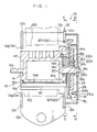
- FIG. 1 an overall structure of the webbing retractor 10 relating to the present embodiment is illustrated in cross-section.
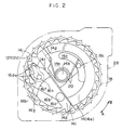
- Figs. 2 and 3 the webbing retractor 10 as seen from the directions of C-C and D-D in Fig. 1 is shown in side view.
- direction A and direction B are shown in Figs. 1 through 6, direction A indicates a webbing pull -out direction, and direction B indicates a webbing take-up direction.
- the webbing retractor 10 has a frame 12.
- the frame 12 has a pair of opposing leg pieces 12a, 12b, and a back piece 12c which connects the leg pieces 12a, 12b.
- the frame 12 is thereby formed in a substantial U-shape as seen in plan view.
- the back piece 12c extends downward, and the lower end portion thereof is fastened and fixed by bolts to a vehicle body.
- Ratchet teeth 12d, 12e which serve as lock teeth are formed by punching in the leg pieces 12a, 12b of the frame 12.
- Ratchet teeth 12f, 12g of the internal ratchets 12d, 12e are set to have high strength.
- a rotation shaft 14a is formed integrally with one end portion of the spool 14.
- a power spring (not shown) is connected to the distal end portion of the rotation shaft 14a, such that the spool 14 is rotatably supported in a state of always being urged to rotate in direction B (see Fig. 2).
- a rotation shaft 14b is formed integrally with the other end portion of the spool 14.
- the spool 14 is rotatably supported at the small diameter shaft 14c by a bearing portion 28c of a sensor holder 28 which will be described later. Further, one end of a webbing 50 is anchored on the spool 14. Due the spool 14 rotating, the webbing 50 is freely taken-up onto and pulled-out from the spool 14.
- a cut-out portion 14d is formed at the outer surface of the spool 14.
- the cut-out portion 14d is separated by a predetermined distance from a center line of end surfaces 14e, 14f of the spool 14, and is formed along the entire length of the spool 14 except for the portions at which the rotation shafts 14a, 14b and the small diameter shaft 14c are formed.
- the bottom portion of the cut-out portion 14d is formed as a semicircular arc (see Fig. 5 for example) .
- load receiving surfaces 14g, 14h are formed at the end surfaces 14e, 14f of the spool 14, respectively.
- the load receiving surfaces 14g, 14h are each formed by a circular arc which is concentric with the semicircular arc of the bottom portion of the cut-out portion 14d and by a step in the axial direction of the spool 14 which is formed lower at the outer side of this circular arc.
- Step portions 14j, 14k are formed in the end surfaces 14e, 14f of the spool 14 along a wall surface 14i at the rotating shaft 14a, 14b sides of the cut-out portion 14d.
- the rotating shaft 14a, 14b sides of the step portions 14j, 14k are formed to be higher than the upper portions of the load receiving surfaces 14g, 14h.
- Abutment portions 141, 14m are formed at the further sides of the load receiving surfaces 14g, 14h as seen from the cut-out portion 14d.
- a first concave portion 14n is formed around the rotation shaft 14b of the end surface 14e of the spool 14.
- a second concave portion 140 which is formed in a circular arc shape concentric with the rotation shaft 14b, is formed in the first concave portion 14n.
- a spring receiving portion 14p is formed at one portion of the wall surface forming the first concave portion 14n.
- a connecting shaft 16a of a lock plate 16 is swingably inserted into the cut-out portion 14d of the spool 14.
- the connecting shaft 16a is formed as a solid cylinder having a smaller diameter than the circular arc of the bottom portion of the cut-out portion 14d of the spool 14.
- Pawls 16b, 16c are connected to end portions of the connecting shaft 16a.
- Lock claws 16d, 16e which can engage with the ratchet teeth 12f, 12g of the frame 12, are formed at the distal end portions of the pawls 16b, 16c.
- the distal end portions of the pawls 16b, 16c, including the lock claws 16d, 16e, are formed to be thick toward the inner side of the lock plate 16.
- operation surfaces 16f, 16g are formed.
- the operation surfaces 16f, 16g are formed from circular arcs which are concentric with the connecting shaft 16a and which have the same diameters as the load receiving surfaces 14g, 14h of the spool 14.
- the pawls 16b, 16c are disposed along the end surfaces 14e, 14f of the spool in a state in which the operation surfaces 16f, 16g oppose the load receiving surfaces 14g, 14h of the spool 14 and the lock claws 16d, 16e oppose the internal ratchets 12d, 12e of the frame 12 at the inner sides thereof. In this way, when the pawl 16b and the pawl 16c are slid (guided) in direction B relative to the spool 14, the lock claws 16d, 16e can engage (self-lock) with the ratchet teeth 12f, 12g.
- the load applied to the lock plate 16 is supported by the spool 14, and the lock plate 16 can be prevented from falling out from the spool 14. Further, the range of swinging of the lock plate 16 is limited due to the lock plate 16 abutting the abutment portions 141, 14m of the spool 14.
- a guide pin 16h is formed at the pawl 16b of the lock plate 16.
- the guide pin 16h is formed as a solid cylindrical projection, and stands erect at the side of the pawl 16b which side, as seen from the connecting shaft 16a, is further ahead of the operation surface 16f and is at the side opposite the side at which the spool 14 is provided.
- the lock plate 16 is formed from an aluminum zinc alloy, and is molded integrally by die casting (i.e., is machined as a single part).
- a V gear 18 is provided at the outer side of the leg piece 12a of the frame 12.
- the V gear 18 is formed substantially as a disc having a larger diameter than the end surface 14e of the spool 14.
- a hollow cylindrical boss 18a is formed at the axially central portion of the V gear 18.
- the rotation shaft 14b of the spool 14 is inserted into the boss 18a such that the V gear 18 is rotatably supported coaxially with the spool 14.
- a substantially backward-S-shaped guide hole 18b is formed in the V gear 18.
- the guide pin 16h which stands at the pawl 16b of the lock plate 16 is inserted into the guide hole 18b.
- the guide hole 18b guides the lock plate 16, via the guide pin 16h, to a position at which the lock plate 16 can engage with the internal ratchets 12d, 12e (i.e., swings the lock plate 16 in direction B relative to the spool 14).
- a supporting projection 18c is provided at the spool 14 side surface of the V gear 18.
- the distal end portion of the supporting projection 18c is inserted into the second concave portion 14o provided at the end surface 14e of the spool 14.
- the return spring 20 is disposed within the first concave portion 14n around the rotation shaft 14b, in a state in which the other end portion of the return spring 20 is engaged with the spring receiving portion 14p of the spool 14.
- the lock plate 16 is urged in direction A with respect to the spool 14, via the guide pin 16h, the V gear 18 (the guide hole 18b), and the return spring 20.
- the lock plate 16 abuts the abutment portions 141, 14m of the spool 14, so as to not obstruct rotation of the spool 14.
- the V gear 18 as well usually rotates integrally with the spool 14.
- Anchor portions 18d are provided at the surface of the V gear 18 at the side opposite the spool 14 side.
- the anchor portions 18d are, as seen in plan view, formed in circular arc shapes which are coaxial with the boss 18a, and are disposed at two locations which are symmetrical with respect to the boss 18a.
- a supporting shaft 18e is provided at the anchor portion 18d side surface of the V gear 18.
- the supporting shaft 18e is formed in a solid cylindrical shape, and is disposed at a position which is substantially symmetrical, around the boss 18a, to the guide hole 18b.
- a sensor anchor portion 18f which is formed in a circular arc shape which is concentric with the supporting shaft 18e as seen in plan view, is formed in a vicinity of the supporting shaft 18e at the same side surface of the V gear 18.
- a stopper 18g which corresponds to the configuration of a sensor pawl 24 which will be described later, is formed in a vicinity of the supporting shaft 18e and the sensor anchor portion 18f.
- a spring hole 18h is provided in the V gear 18.
- a spring receiving portion 18i is formed at the end surface of the spring hole 18h which end surface substantially opposes the supporting shaft 18e.
- a plurality of external teeth 18j are formed at uniform intervals in the outer peripheral portion of the V gear 18.
- the external teeth 18j are formed so as to be engageable with a sensor lever 46 of a V sensor 40 which will be described later.
- an inertia plate 22 is provided at the side of the V gear 18 opposite the spool 14 side.
- the inertia plate 22 is formed as a disc from which two peripheral portions, which are symmetrical with respect to the axis of rotation, have been cut out.
- a support hole 22a is formed in the axially central portion of the inertia plate 22.
- Anchor holes 22b which are formed in circular arc shapes which are concentric with the support hole 22 as seen in plan view, are formed at two positions in the inertia plate 22 which are symmetrical with respect to the support hole 22a.
- the support hole 22a and the anchor holes 22b correspond to the boss 18a and the anchor portions 18d of the V gear 18.
- the boss 18a is inserted into the support hole 22a, and the anchor portions 18d are inserted into the anchor holes 22b.
- the anchor portions 18d engage with the inner peripheral portions of the anchor holes 22b, and the inertia plate 22 is supported so as to be coaxial with the V gear 18 (the spool 14), and so as to be swingable, and so as to not fall off.
- the circular arc of the anchor hole 22b is formed to be longer (to have a greater angle of circumference) than the circular arc of the anchor portion 18d.
- the inertia plate 22 is disposed so as to be able to swing in direction B with respect to the V gear 18, in a range of the difference between the lengths (the angles of circumference) of these circular arcs.
- engagement projections 22c are formed at the surfaces opposing direction A, at the cut-out portions of the inertia plate 22.
- the sensor pawl 24 is connected to the supporting shaft 18e of the V gear 18.
- the sensor pawl 24 includes a distal end portion 24a which engages with internal teeth 28b formed at the sensor holder 28 which will be described later; a shaft hole 24b into which the supporting shaft 18e is inserted; an anchor projection 24c which anchors on the sensor anchor portion 18f; and a spring receiving portion 24d.
- the sensor pawl 24 is swingably supported at the side surface of the V gear 18 in a state in which the support shaft 18e of the V gear 18 is inserted into the shaft hole 24b.
- the anchor projection 24c is anchored on the sensor anchor portion 18f such that the sensor pawl 24 can be prevented from falling off.
- the range of swinging of the sensor pawl 24 is limited by the stopper 18g which corresponds to the configuration of the sensor pawl 24.
- the spring receiving portion 24d of the sensor pawl 24 is inserted into one end portion of a coil spring 26.
- the coil spring 26 is held within the spring hole 18h of the V gear 18 in a state in which the spring receiving portion 18i of the V gear 18 is inserted into the other end portion of the coil spring 26.
- the sensor pawl 24 is engaged with the engagement projection 22c of the inertia plate 22.
- the sensor pawl 24 and the inertia plate 22 are urged in direction A with respect to the V gear 18, and usually rotate (revolve around the rotation shaft 14b) integrally with the V gear 18 without swinging.
- the sensor holder 28 is fixed and held at the outer side of the leg piece 12a of the frame 12.
- the sensor holder 28 is formed in a substantial cap shape, and is fixed and held at the outer side of the leg piece 12a in a state in which the opening portion thereof opposes the leg piece 12a and in which the V gear 18, the inertia plate 22, the sensor pawl 24, and the like are accommodated within the interior thereof.
- a hollow cylindrical portion 28a is formed at the inner portion of the sensor holder 28.
- the internal teeth 28b are formed at the inner surface of the cylindrical portion 28a.
- the internal teeth 28b are disposed at the outer side of the sensor pawl 24. When the sensor pawl 24 swings in direction B relative to the V gear 18, the internal teeth 28b can engage with the distal end portion 24a of the sensor pawl 24.
- the inertia plate 22, the sensor pawl 24, the coil spring 26, and the internal teeth 28b form a W sensor 30 which forms a WSIR.
- the bearing portion 28c is provided at the axially central portion of the sensor holder 28. As described above, the bearing portion 28c rotatably supports the small diameter shaft 14c of the spool 14.
- a holder portion 28e is formed integrally with the outer peripheral portion of the sensor holder 28.
- the V sensor (acceleration sensor) 40 which together with the external teeth 18j of the V gear 18 forms a VSIR, is provided in the holder portion 28e. Note that the V sensor 40 is not shown in Fig. 1.
- the V sensor 40 has a housing 42, and the housing 42 is fixed and held at a holder portion 28e of the sensor holder 28.
- a bottom surface 42a which is V-shaped and has a shallow bottom, is formed at the housing 42.
- a ball 44 is placed on the bottom surface 42a.
- the sensor lever 46 is connected to the housing 42.
- the sensor lever 46 is supported at the housing 42 so as to be freely swingable, by a support shaft 42b provided at the housing 42 being inserted into a shaft hole 46a provided at a substantially central portion of the sensor lever 46.
- the sensor lever 46 includes a distal end portion 46b which can engage with the external teeth 18j of the V gear 18, and an abutment portion 46c which is formed at the side of the shaft hole 46a opposite the side at which the distal end portion 46b is provided and whose inertial moment is greater than that of the distal end portion 46b.
- the abutment portion 46c abuts and is set on the ball 44.
- the distal end portion 46b is, due to gravity, positioned at a position of non-engagement with the external teeth 18j of the V gear 18.
- the non-engaged state of the distal end portion 46b and the external teeth 18j of the V gear 18 is usually maintained due to gravity.
- the sensor lever 46 swings, such that the distal end portion 46b moves to a position of engagement with the external teeth 18j of the V gear 18.
- the spool 14 is supported so as to be freely rotatable, and the lock plate 16 and the V gear 18 are urged in the webbing pull-out direction (direction A) by the return spring 20.
- the spool 14, the lock plate 16, and the V gear 18 rotate integrally.
- the sensor pawl 24 of the W sensor 30 is urged in direction A by the coil spring 26, and the sensor lever 42 of the V sensor 40 is held on the ball 46 due to gravity.
- the W sensor 30 and the V sensor 40 do not operate. Therefore, usually, the webbing 50 can be freely taken-up and pulled-out.
- the V sensor 40 operates, the sensor lever 46 engages the external tooth 18j of the V gear 18, and rotation of the V gear 18 in direction A is impeded.
- the W sensor 30 operates, and the sensor pawl 24 engages with the internal tooth 28b of the sensor holder 28 which is fixed to the frame 12, and rotation of the V gear 18 in direction A is impeded.
- the lock plate 16 (the connecting shaft 16a) is inserted into the spool 14, with the connecting shaft 16a being inserted first, from the opening, along the spool rotational axis, of the cut-out portion 14d which is formed along the entire length of the outer surface of the spool 14.
- the lock plate 16 When the connecting shaft 16a is inserted into the spool, by rotating the lock plate 16 appropriately around the connecting shaft 16a such that the operation surfaces 16f, 16g oppose the load receiving surfaces 14g, 14h of the spool 14, the lock plate 16 is positioned at a predetermined position (the position at which the pawls 16b, 16c abut the abutment portions 141, 14m of the spool 14). Thereafter, in this state, the other parts, such as the V gear 18 and the like, are assembled.
- the lock plate 16 is molded integrally as a single part by die casting. Thus, there is no need to assemble the connecting shaft 16a and the pawls 16b, 16c, and there is no need for processes for assembling the lock plate 16. Further, because the lock plate 16 is molded integrally, there are no limits on the configuration (design) accompanying the formation of the portions connecting the connecting shaft 16a and the pawls 16b, 16c, and the degrees of freedom of the configuration of the lock plate 16 can be increased. Moreover, the dimensional precision of the lock plate 16 is provided by the precision of machining alone, and there is no need to consider the precision of assembly. Thus, constant dimensional accuracy can be obtained easily.
- the structure of the lock plate 16 can be simplified, the lock plate 16 can easily be assembled to the spool 14, and the workability is improved.
- the lock plate 16 is formed from an aluminum zinc alloy, and is molded integrally by die casting.
- the present invention is not limited to the same, and the material and method of molding the lock plate can be appropriately selected.
- formation of the lock plate is not limited to integral molding, and for example, the lock plate may be assembled as a single part by welding or the like before being assembled to the spool.
- the present invention is not limited to the same, and a various mechanisms may be added. Accordingly, for example, a pretensioner mechanism, in which the vehicle occupant is restrained by taking-up the webbing by a given amount at the time of a rapid deceleration of the vehicle, or a force limiter mechanism, which, after pulling-out of the webbing is impeded, permits the webbing to be pulled-out by a predetermined amount and absorbs energy, or the like may be added.
- the lock plate is not limited to a structure which is directly set at the spool.
- the lock plate may be connected to the spool via a lock base which is connected to a torsion bar and which is provided with a cut-out portion corresponding to the cut-out portion of the spool.
- the webbing retractor 10 is structured to include both the W sensor 30, which senses rapid pulling-out of the webbing and impedes rotation of the V gear 18 in direction A, and the V sensor 40, which senses rapid deceleration of the vehicle and impedes rotation of the V gear 18 in direction A.
- the present invention is not limited to the same, and may be structured so as to include only one of the W sensor 30 and the V sensor 40. Further, the structures of the W sensor and the V sensor are not limited to the structures of the above-described W sensor 30 and V sensor 40.
Landscapes
- Engineering & Computer Science (AREA)
- Mechanical Engineering (AREA)
- Automotive Seat Belt Assembly (AREA)
Abstract
Description
- The present invention relates to a webbing retractor, and in particular, to a webbing retractor which can impede rotation of a spool in a webbing pull-out direction at a time when a vehicle rapidly decelerates or at a time when the webbing is rapidly pulled-out.
- Generally, in a webbing retractor, a webbing is wound in a roll form on a hollow cylindrical spool supported at a frame which is formed in a substantial U-shape as seen in plan view and which is fixed to a vehicle. Usually, the webbing can be freely taken-up or pulled-out due to the spool rotating freely. Further, in the webbing retractor, a WSIR (webbing sensitive inertia reel) or a VSIR (vehicle sensitive inertia reel) is utilized in order to impede pulling-out of the webbing when a rapid deceleration of the vehicle or a rapid pulling-out of the webbing is sensed.
- A WSIR or a VSIR is equipped with a lock function to impede rotation of the spool in the webbing pull-out direction, in order to impede pulling-out of the webbing in the above-described cases. An example of such a lock mechanism is the lock mechanism disclosed in Japanese Patent Application (JP-A) No. 5-246303 in which a main pawl and a back-up pawl (lock plate) are disposed at the both sides of a reel shaft (spool), and due to the main pawl and the back-up pawl engaging with teeth (lock teeth) formed at a frame, rotation of the reel shaft in the webbing pull-out direction is impeded. In such a conventional lock mechanism, rotation of the reel shaft in the webbing pull-out direction can be reliably impeded in predetermined cases, and the webbing retractor can be made lighter-weight (e.g., the main pawl and the back-up pawl can be made thinner) because the load at the time of locking is dispersed at the main pawl and the back-up pawl which are provided at the both sides of the reel shaft.
- In the above-described conventional webbing retractor, when placing the main pawl and the back-up pawl at the both ends of the reel shaft, in a state in which the main pawl is inserted into one end of a joint pin, the joint pin is inserted into a through hole formed in the spool. Further, in this state, the back-up pawl is mounted to the other end portion of the joint pin. Namely, at the time that three parts which are the joint pin, the main pawl and the back-up pawl are assembled to the spool, they are connected so as to be interlocking.
- Thus, the workability in assembling the main pawl and the back-up pawl to the reel shaft is poor. Moreover, the number of parts forming the lock mechanism is large, and accordingly, there is the problem that the number of assembly processes is large.
- In view of the above circumstances, an object of the present invention is to provide a webbing retractor in which the structure of a lock plate can be simplified, it is easy to assemble a lock plate to a spool, and workability is improved.
- In order to achieve the above object, a webbing retractor relating to the present invention comprises: a spool which is tube-shaped and on which a webbing is taken-up and from which the webbing is pulled-out; a cut-out portion formed over an entire length of an outer surface of the spool along a rotational axis of the spool, a bottom portion of the cut-out portion being circular-arc-shaped; a frame which is fixed and held at a vehicle, and which rotatably supports the spool between a pair of leg pieces, and at which lock teeth are formed at an inner surface of an opening of each leg piece; and a lock plate having a pair of pawls formed so as to be engageable with the lock teeth, and a connecting shaft which has a circular cross-section and which connects the pair of pawls, and due to the connecting shaft being inserted into and disposed in the cut-out portion, the pair of pawls are disposed so as to oppose the lock teeth at both end portions of the spool, and in a predetermined case, due to due to the pair of pawls engaging with the lock teeth, the lock plate impedes rotation of the spool in a webbing pull-out direction.
- In the above-described webbing retractor, usually, the lock plate is disposed so as to oppose the lock teeth, and the lock plate and the lock teeth are in a non-engaged state. Thus, rotation of the spool is not limited, and the webbing can be freely taken-up and pulled-out.
- On the other hand, in a predetermined case such as, for example, at a time when the vehicle rapidly decelerates or the webbing is rapidly pulled-out, the lock plate, which is provided with the pair of pawls disposed at the both end portions of the spool, engages with the lock teeth formed at the pair of leg pieces forming the frame, and rotation of the spool in the webbing pull-out direction is thereby hindered.
- Here, when the lock plate, which is provided with the pair of pawls disposed at the both end portions of the spool, is assembled to the spool, first, the pawls are connected to the both ends of the connecting shaft, and the lock plate is formed as a single part. When the lock plate is formed, the connecting shaft is inserted into the spool from the opening, along the spool rotating shaft, of the cut-out portion which is formed along the entire length of the outer surface of the spool. When the connecting shaft is inserted into the spool, due to the lock plate being appropriately rotated around the connecting shaft, the lock plate is disposed at a predetermined position. In this state, other parts, such as a V gear forming a WSIR or a VSIR, or the like, are assembled.
- In this way, in the webbing retractor of the present invention, there is no need to mount a pawl in the state in which a connecting shaft is inserted into a through hole of a spool, as in the conventional art. By inserting the connecting shaft of the lock plate, which is a single part, into the spool from the cut-out portion, the lock plate can be assembled to the spool. Thus, the structure of the lock plate can be simplified, the assembly of the lock plate to the spool is easy, and workability improves.
- In the webbing retractor relating to the present invention, preferably, at the lock plate, the pair of pawls and the connecting shaft are formed integrally.
- In this webbing retractor, the lock plate, which has the pair of pawls and the connecting shaft, is formed integrally (integrally molded) as a single part in a part machining step. Thus, at the time when the lock plate is assembled to the spool, there is no need to connect the pawls to the both ends of the connecting shaft. As a result, when assembling the lock plate to the spool, it suffices to insert the connecting shaft of the lock plate, which is a single part, into the spool from the cut-out portion of the spool, and to rotate the lock plate appropriately.
- Further, because the lock plate is molded integrally, there are no limits on the configuration accompanying the formation of the portions which connect the pawls and the connecting shaft. Thus, the degrees of freedom of the shape (design) of the lock plate can be increased. Moreover, the dimensional precision of the lock plate is provided by the precision of machining alone, and there is no need to consider the precision of assembly. Thus, constant dimensional precision can easily be obtained.
- In this way, in the preferable webbing retractor of the present invention, the structure of the lock plate can be simplified even more, the assembly of the lock plate to the spool can be simplified even more, and workability improves.
-
- Fig. 1 is a schematic sectional view showing an overall structure of a webbing retractor relating to an embodiment of the present invention.
- Fig. 2 is a side view, as seen from direction C-C in Fig. 1, showing an unlocked state of the webbing retractor relating to the embodiment of the present invention.
- Fig. 3 is a side view, as seen from direction D-D in Fig.
1, showing a non-operating state of a
W sensor 30 which forms the webbing retractor relating to the embodiment of the present invention. - Fig. 4A is a right side view showing a spool which forms the webbing retractor relating to the embodiment of the present invention.
- Fig. 4B is a left side view showing the spool which forms the webbing retractor relating to the embodiment of the present invention.
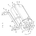
- Fig. 5 is a perspective view illustrating the spool and a lock plate which form the webbing retractor relating to the embodiment of the present invention.
- Fig. 6 is a plan view showing a V gear which forms the webbing retractor relating to the embodiment of the present invention.
-
- A
webbing retractor 10 relating to an embodiment of the present invention will be described on the basis of Figs. 1 through 6. - In Fig. 1, an overall structure of the
webbing retractor 10 relating to the present embodiment is illustrated in cross-section. In Figs. 2 and 3, thewebbing retractor 10 as seen from the directions of C-C and D-D in Fig. 1 is shown in side view. When direction A and direction B are shown in Figs. 1 through 6, direction A indicates a webbing pull -out direction, and direction B indicates a webbing take-up direction. - As shown in Fig. 1, the
webbing retractor 10 has a frame 12. The frame 12 has a pair ofopposing leg pieces back piece 12c which connects theleg pieces back piece 12c extends downward, and the lower end portion thereof is fastened and fixed by bolts to a vehicle body. -
Internal ratchets leg pieces Ratchet teeth internal ratchets - A hollow
cylindrical spool 14, whose axial direction is the direction in which theleg pieces opposing leg pieces rotation shaft 14a is formed integrally with one end portion of thespool 14. A power spring (not shown) is connected to the distal end portion of therotation shaft 14a, such that thespool 14 is rotatably supported in a state of always being urged to rotate in direction B (see Fig. 2). On the other hand, arotation shaft 14b is formed integrally with the other end portion of thespool 14. Asmall diameter shaft 14c, whose diameter is small, is formed integrally at the distal end of therotation shaft 14b. Thespool 14 is rotatably supported at thesmall diameter shaft 14c by a bearingportion 28c of asensor holder 28 which will be described later. Further, one end of awebbing 50 is anchored on thespool 14. Due thespool 14 rotating, thewebbing 50 is freely taken-up onto and pulled-out from thespool 14. - As shown in Figs. 4A, 4B and 5, a cut-out
portion 14d is formed at the outer surface of thespool 14. The cut-outportion 14d is separated by a predetermined distance from a center line ofend surfaces spool 14, and is formed along the entire length of thespool 14 except for the portions at which therotation shafts small diameter shaft 14c are formed. The bottom portion of the cut-outportion 14d is formed as a semicircular arc (see Fig. 5 for example) . Further, load receivingsurfaces spool 14, respectively. Theload receiving surfaces portion 14d and by a step in the axial direction of thespool 14 which is formed lower at the outer side of this circular arc.Step portions spool 14 along awall surface 14i at therotating shaft portion 14d. Therotating shaft step portions load receiving surfaces Abutment portions load receiving surfaces portion 14d. - A first
concave portion 14n is formed around therotation shaft 14b of theend surface 14e of thespool 14. A secondconcave portion 140, which is formed in a circular arc shape concentric with therotation shaft 14b, is formed in the firstconcave portion 14n. Aspring receiving portion 14p is formed at one portion of the wall surface forming the firstconcave portion 14n. - As shown in Figs. 2 and 5, a connecting
shaft 16a of alock plate 16 is swingably inserted into the cut-outportion 14d of thespool 14. The connectingshaft 16a is formed as a solid cylinder having a smaller diameter than the circular arc of the bottom portion of the cut-outportion 14d of thespool 14.Pawls shaft 16a.Lock claws ratchet teeth pawls pawls lock claws lock plate 16. At the step portions at the boundaries between these thick and thin portions, operation surfaces 16f, 16g are formed. The operation surfaces 16f, 16g are formed from circular arcs which are concentric with the connectingshaft 16a and which have the same diameters as theload receiving surfaces spool 14. - The
pawls load receiving surfaces spool 14 and thelock claws internal ratchets pawl 16b and thepawl 16c are slid (guided) in direction B relative to thespool 14, thelock claws ratchet teeth lock plate 16 with theinternal ratchets load receiving surfaces lock plate 16 is supported by thespool 14, and thelock plate 16 can be prevented from falling out from thespool 14. Further, the range of swinging of thelock plate 16 is limited due to thelock plate 16 abutting theabutment portions spool 14. - A
guide pin 16h is formed at thepawl 16b of thelock plate 16. Theguide pin 16h is formed as a solid cylindrical projection, and stands erect at the side of thepawl 16b which side, as seen from the connectingshaft 16a, is further ahead of theoperation surface 16f and is at the side opposite the side at which thespool 14 is provided. - The
lock plate 16 is formed from an aluminum zinc alloy, and is molded integrally by die casting (i.e., is machined as a single part). - As shown in Fig. 3, a
V gear 18 is provided at the outer side of theleg piece 12a of the frame 12. TheV gear 18 is formed substantially as a disc having a larger diameter than theend surface 14e of thespool 14. A hollow cylindrical boss 18a is formed at the axially central portion of theV gear 18. Therotation shaft 14b of thespool 14 is inserted into the boss 18a such that theV gear 18 is rotatably supported coaxially with thespool 14. A substantially backward-S-shapedguide hole 18b is formed in theV gear 18. Theguide pin 16h which stands at thepawl 16b of thelock plate 16 is inserted into theguide hole 18b. In this way, when relative rotation arises between thespool 14 and theV gear 18, theguide hole 18b guides thelock plate 16, via theguide pin 16h, to a position at which thelock plate 16 can engage with theinternal ratchets lock plate 16 in direction B relative to the spool 14). - Further, as shown in Fig. 6, a supporting
projection 18c is provided at thespool 14 side surface of theV gear 18. The distal end portion of the supportingprojection 18c is inserted into the second concave portion 14o provided at theend surface 14e of thespool 14. One end portion of areturn spring 20, which is a torsion coil spring, engages with the supportingprojection 18c. Thereturn spring 20 is disposed within the firstconcave portion 14n around therotation shaft 14b, in a state in which the other end portion of thereturn spring 20 is engaged with thespring receiving portion 14p of thespool 14. In this way, thelock plate 16 is urged in direction A with respect to thespool 14, via theguide pin 16h, the V gear 18 (theguide hole 18b), and thereturn spring 20. Usually, thelock plate 16 abuts theabutment portions spool 14, so as to not obstruct rotation of thespool 14. In this way, theV gear 18 as well usually rotates integrally with thespool 14. -
Anchor portions 18d are provided at the surface of theV gear 18 at the side opposite thespool 14 side. Theanchor portions 18d are, as seen in plan view, formed in circular arc shapes which are coaxial with the boss 18a, and are disposed at two locations which are symmetrical with respect to the boss 18a. A supportingshaft 18e is provided at theanchor portion 18d side surface of theV gear 18. The supportingshaft 18e is formed in a solid cylindrical shape, and is disposed at a position which is substantially symmetrical, around the boss 18a, to theguide hole 18b. Asensor anchor portion 18f, which is formed in a circular arc shape which is concentric with the supportingshaft 18e as seen in plan view, is formed in a vicinity of the supportingshaft 18e at the same side surface of theV gear 18. Astopper 18g, which corresponds to the configuration of asensor pawl 24 which will be described later, is formed in a vicinity of the supportingshaft 18e and thesensor anchor portion 18f. Aspring hole 18h is provided in theV gear 18. Aspring receiving portion 18i is formed at the end surface of thespring hole 18h which end surface substantially opposes the supportingshaft 18e. - A plurality of
external teeth 18j are formed at uniform intervals in the outer peripheral portion of theV gear 18. Theexternal teeth 18j are formed so as to be engageable with asensor lever 46 of aV sensor 40 which will be described later. - As shown in Figs. 1 and 3, an
inertia plate 22 is provided at the side of theV gear 18 opposite thespool 14 side. Theinertia plate 22 is formed as a disc from which two peripheral portions, which are symmetrical with respect to the axis of rotation, have been cut out. Asupport hole 22a is formed in the axially central portion of theinertia plate 22. Anchor holes 22b, which are formed in circular arc shapes which are concentric with thesupport hole 22 as seen in plan view, are formed at two positions in theinertia plate 22 which are symmetrical with respect to thesupport hole 22a. Thesupport hole 22a and the anchor holes 22b correspond to the boss 18a and theanchor portions 18d of theV gear 18. The boss 18a is inserted into thesupport hole 22a, and theanchor portions 18d are inserted into the anchor holes 22b. Theanchor portions 18d engage with the inner peripheral portions of the anchor holes 22b, and theinertia plate 22 is supported so as to be coaxial with the V gear 18 (the spool 14), and so as to be swingable, and so as to not fall off. Further, the circular arc of theanchor hole 22b is formed to be longer (to have a greater angle of circumference) than the circular arc of theanchor portion 18d. Theinertia plate 22 is disposed so as to be able to swing in direction B with respect to theV gear 18, in a range of the difference between the lengths (the angles of circumference) of these circular arcs. Further,engagement projections 22c are formed at the surfaces opposing direction A, at the cut-out portions of theinertia plate 22. - The
sensor pawl 24 is connected to the supportingshaft 18e of theV gear 18. Thesensor pawl 24 includes a distal end portion 24a which engages withinternal teeth 28b formed at thesensor holder 28 which will be described later; ashaft hole 24b into which the supportingshaft 18e is inserted; an anchor projection 24c which anchors on thesensor anchor portion 18f; and aspring receiving portion 24d. - As shown in Fig. 3, the
sensor pawl 24 is swingably supported at the side surface of theV gear 18 in a state in which thesupport shaft 18e of theV gear 18 is inserted into theshaft hole 24b. In this state, the anchor projection 24c is anchored on thesensor anchor portion 18f such that thesensor pawl 24 can be prevented from falling off. Further, the range of swinging of thesensor pawl 24 is limited by thestopper 18g which corresponds to the configuration of thesensor pawl 24. Moreover, thespring receiving portion 24d of thesensor pawl 24 is inserted into one end portion of acoil spring 26. Thecoil spring 26 is held within thespring hole 18h of theV gear 18 in a state in which thespring receiving portion 18i of theV gear 18 is inserted into the other end portion of thecoil spring 26. In this state, thesensor pawl 24 is engaged with theengagement projection 22c of theinertia plate 22. Thus, thesensor pawl 24 and theinertia plate 22 are urged in direction A with respect to theV gear 18, and usually rotate (revolve around therotation shaft 14b) integrally with theV gear 18 without swinging. - The
sensor holder 28 is fixed and held at the outer side of theleg piece 12a of the frame 12. Thesensor holder 28 is formed in a substantial cap shape, and is fixed and held at the outer side of theleg piece 12a in a state in which the opening portion thereof opposes theleg piece 12a and in which theV gear 18, theinertia plate 22, thesensor pawl 24, and the like are accommodated within the interior thereof. A hollowcylindrical portion 28a is formed at the inner portion of thesensor holder 28. Theinternal teeth 28b are formed at the inner surface of thecylindrical portion 28a. Theinternal teeth 28b are disposed at the outer side of thesensor pawl 24. When thesensor pawl 24 swings in direction B relative to theV gear 18, theinternal teeth 28b can engage with the distal end portion 24a of thesensor pawl 24. - In the above-described structure, the
inertia plate 22, thesensor pawl 24, thecoil spring 26, and theinternal teeth 28b form aW sensor 30 which forms a WSIR. - The bearing
portion 28c is provided at the axially central portion of thesensor holder 28. As described above, the bearingportion 28c rotatably supports thesmall diameter shaft 14c of thespool 14. - A
holder portion 28e is formed integrally with the outer peripheral portion of thesensor holder 28. The V sensor (acceleration sensor) 40, which together with theexternal teeth 18j of theV gear 18 forms a VSIR, is provided in theholder portion 28e. Note that theV sensor 40 is not shown in Fig. 1. - As shown in Fig. 3, the
V sensor 40 has ahousing 42, and thehousing 42 is fixed and held at aholder portion 28e of thesensor holder 28. A bottom surface 42a, which is V-shaped and has a shallow bottom, is formed at thehousing 42. Aball 44 is placed on the bottom surface 42a. Thesensor lever 46 is connected to thehousing 42. Thesensor lever 46 is supported at thehousing 42 so as to be freely swingable, by asupport shaft 42b provided at thehousing 42 being inserted into a shaft hole 46a provided at a substantially central portion of thesensor lever 46. Thesensor lever 46 includes adistal end portion 46b which can engage with theexternal teeth 18j of theV gear 18, and anabutment portion 46c which is formed at the side of the shaft hole 46a opposite the side at which thedistal end portion 46b is provided and whose inertial moment is greater than that of thedistal end portion 46b. Theabutment portion 46c abuts and is set on theball 44. In this state, thedistal end portion 46b is, due to gravity, positioned at a position of non-engagement with theexternal teeth 18j of theV gear 18. In this way, at theV sensor 40, the non-engaged state of thedistal end portion 46b and theexternal teeth 18j of theV gear 18 is usually maintained due to gravity. At the time of rapid deceleration of the vehicle, due to theball 44 rolling on a seat surface 44a, thesensor lever 46 swings, such that thedistal end portion 46b moves to a position of engagement with theexternal teeth 18j of theV gear 18. - Next, operation of the present embodiment will be described.
- In the
webbing retractor 10 having the above-described structure, thespool 14 is supported so as to be freely rotatable, and thelock plate 16 and theV gear 18 are urged in the webbing pull-out direction (direction A) by thereturn spring 20. Thus, usually, thespool 14, thelock plate 16, and theV gear 18 rotate integrally. Further, usually, thesensor pawl 24 of theW sensor 30 is urged in direction A by thecoil spring 26, and thesensor lever 42 of theV sensor 40 is held on theball 46 due to gravity. Thus, theW sensor 30 and theV sensor 40 do not operate. Therefore, usually, thewebbing 50 can be freely taken-up and pulled-out. - On the other hand, at the time of a sudden deceleration of the vehicle, the
V sensor 40 operates, thesensor lever 46 engages theexternal tooth 18j of theV gear 18, and rotation of theV gear 18 in direction A is impeded. - Further, at the time when the
webbing 50 is rapidly pulled-out, theW sensor 30 operates, and thesensor pawl 24 engages with theinternal tooth 28b of thesensor holder 28 which is fixed to the frame 12, and rotation of theV gear 18 in direction A is impeded. - When rotation of the V gear in direction A is impeded in either of these cases, together with the rotation of the
spool 14 in direction A, thelock plate 16 is guided to a position at which engagement with theinternal ratchets spool 14 rotates further in direction A, thelock plate 16 self-locks with theinternal ratchets spool 14 in direction A is impeded. Further, accompanying this self-locking, operation of theV sensor 40 or theW sensor 30 is cancelled. After the locking of thelock plate 16 and theinternal ratchets webbing 50 can again be pulled-out (thespool 14 can again rotate in direction A). - Here, at the time of assembling the
lock plate 16, at which the connectingshaft 16a and thepawls lock claws guide pin 16h) are molded integrally, to thespool 14, the lock plate 16 (the connectingshaft 16a) is inserted into thespool 14, with the connectingshaft 16a being inserted first, from the opening, along the spool rotational axis, of the cut-outportion 14d which is formed along the entire length of the outer surface of thespool 14. When the connectingshaft 16a is inserted into the spool, by rotating thelock plate 16 appropriately around the connectingshaft 16a such that the operation surfaces 16f, 16g oppose theload receiving surfaces spool 14, thelock plate 16 is positioned at a predetermined position (the position at which thepawls abutment portions V gear 18 and the like, are assembled. - Thus, there is no need to mount a pawl to a connecting shaft in the state in which the connecting shaft is inserted into a through-hole of a spool, as in the conventional art. By inserting the connecting
shaft 16a of thelock plate 16, which is a single part, into thespool 14 from the cut-outportion 14d, thelock plate 16 can be assembled to thespool 14. Further, the operation surfaces 16f, 16g of the lock plate are disposed so as to oppose and so as to be able to abut theload receiving surfaces spool 14. Thus, thelock plate 16 can be prevented from falling out from thespool 14. - Further, the
lock plate 16 is molded integrally as a single part by die casting. Thus, there is no need to assemble the connectingshaft 16a and thepawls lock plate 16. Further, because thelock plate 16 is molded integrally, there are no limits on the configuration (design) accompanying the formation of the portions connecting the connectingshaft 16a and thepawls lock plate 16 can be increased. Moreover, the dimensional precision of thelock plate 16 is provided by the precision of machining alone, and there is no need to consider the precision of assembly. Thus, constant dimensional accuracy can be obtained easily. - In this way, in the
webbing retractor 10 relating to the present embodiment, the structure of thelock plate 16 can be simplified, thelock plate 16 can easily be assembled to thespool 14, and the workability is improved. - Further in the present embodiment, the
lock plate 16 is formed from an aluminum zinc alloy, and is molded integrally by die casting. However, the present invention is not limited to the same, and the material and method of molding the lock plate can be appropriately selected. Further, formation of the lock plate is not limited to integral molding, and for example, the lock plate may be assembled as a single part by welding or the like before being assembled to the spool. - In the
webbing retractor 10 relating to the above-described embodiment, pulling-out of the webbing is impeded in predetermined cases. However, the present invention is not limited to the same, and a various mechanisms may be added. Accordingly, for example, a pretensioner mechanism, in which the vehicle occupant is restrained by taking-up the webbing by a given amount at the time of a rapid deceleration of the vehicle, or a force limiter mechanism, which, after pulling-out of the webbing is impeded, permits the webbing to be pulled-out by a predetermined amount and absorbs energy, or the like may be added. In this case, the lock plate is not limited to a structure which is directly set at the spool. For example, the lock plate may be connected to the spool via a lock base which is connected to a torsion bar and which is provided with a cut-out portion corresponding to the cut-out portion of the spool. - Moreover, in the above-described embodiment, the
webbing retractor 10 is structured to include both theW sensor 30, which senses rapid pulling-out of the webbing and impedes rotation of theV gear 18 in direction A, and theV sensor 40, which senses rapid deceleration of the vehicle and impedes rotation of theV gear 18 in direction A. However, the present invention is not limited to the same, and may be structured so as to include only one of theW sensor 30 and theV sensor 40. Further, the structures of the W sensor and the V sensor are not limited to the structures of the above-describedW sensor 30 andV sensor 40. - As described above, in the webbing retractor relating to the present invention, excellent effects are achieved in that the assembling of the lock plate to the spool is easy, workability is improved, and the number of structural parts of the lock plate can be reduced.
- The features disclosed in the foregoing description, in the claims and/or in the accompanying drawings may, both separately and in any combination thereof, be material for realising the invention in diverse forms thereof.
Claims (10)
- A webbing retractor comprising:a spool which is tube-shaped and on which a webbing is taken-up and from which the webbing is pulled-out;a cut-out portion formed over substantially an entire length of an outer surface of the spool along a rotational axis of the spool, a bottom portion of the cut-out portion being circular-arc-shaped;a frame which is fixed and held at a vehicle, and which rotatably supports the spool between a pair of leg pieces, and at which lock teeth are formed at an inner surface of an opening of each leg piece; anda lock plate having a pair of pawls formed so as to be engageable with the lock teeth, and a connecting shaft which has a circular cross-section and which connects the pair of pawls, and due to the connecting shaft being inserted into and disposed in the cut-out portion, the pair of pawls are disposed so as to oppose the lock teeth at both end portions of the spool, and in a predetermined case, due to the pair of pawls engaging with the lock teeth, the lock plate impedes rotation of the spool in a webbing pull-out direction.
- A webbing retractor according to claim 1, wherein, at the lock plate, the pair of pawls and the connecting shaft are formed integrally.
- A webbing retractor according to claim 2, wherein the lock plate is integrally molded by die casting.
- A webbing retractor according to claim 2, wherein the lock plate is assembled as a single part by welding.
- A webbing retractor according to any of claims 1 through 4, further comprising a gear formed substantially as a disc whose diameter is larger than a diameter of one end surface of the spool, the gear being provided at an outer side of one of the leg pieces of the frame.
- A webbing retractor according to claim 5, further comprising at least one sensor for controlling operation of the webbing retractor.
- A webbing retractor according to claim 6, wherein the sensor is a webbing sensor, and the webbing sensor is accommodated within a holder provided at an outer side of one of the leg pieces of the frame.
- A webbing retractor according to claim 7, wherein the webbing sensor includes an inertia plate provided at a side of the gear opposite the side at which the spool is disposed, so as to be supported coaxially with the gear and swingably; a pawl which is connected to a supporting shaft of the gear and which is swingable at a side surface of the gear; a spring held in a hole formed in the gear; and internal teeth formed at an inner portion of the holder.
- A webbing retractor according to claim 7 or 8, further comprising an acceleration sensor, wherein the acceleration sensor is accommodated within a housing fixed to one portion of the holder of the webbing sensor.
- A webbing retractor according to claim 9, wherein the acceleration sensor includes a ball placed on a bottom surface of the housing, and a lever which is swingably supported at the housing, and the lever includes a first end portion which is engageable with external teeth of the gear, and a second end portion which can abut an upper portion of the ball.
Applications Claiming Priority (2)
| Application Number | Priority Date | Filing Date | Title |
|---|---|---|---|
| JP2000210534 | 2000-07-11 | ||
| JP2000210534A JP3727514B2 (en) | 2000-07-11 | 2000-07-11 | Webbing take-up device |
Publications (2)
| Publication Number | Publication Date |
|---|---|
| EP1172265A1 true EP1172265A1 (en) | 2002-01-16 |
| EP1172265B1 EP1172265B1 (en) | 2003-12-03 |
Family
ID=18706788
Family Applications (1)
| Application Number | Title | Priority Date | Filing Date |
|---|---|---|---|
| EP01116446A Expired - Lifetime EP1172265B1 (en) | 2000-07-11 | 2001-07-06 | Webbing retractor |
Country Status (7)
| Country | Link |
|---|---|
| US (1) | US6527214B2 (en) |
| EP (1) | EP1172265B1 (en) |
| JP (1) | JP3727514B2 (en) |
| KR (1) | KR100773972B1 (en) |
| CN (1) | CN1153701C (en) |
| AU (1) | AU775359B2 (en) |
| DE (1) | DE60101352T2 (en) |
Cited By (1)
| Publication number | Priority date | Publication date | Assignee | Title |
|---|---|---|---|---|
| EP1172266A2 (en) | 2000-07-12 | 2002-01-16 | Kabushiki Kaisha Tokai Rika Denki Seisakusho | Webbing retractor |
Families Citing this family (19)
| Publication number | Priority date | Publication date | Assignee | Title |
|---|---|---|---|---|
| EP1195767A1 (en) * | 2000-09-27 | 2002-04-10 | Deutsche Thomson-Brandt Gmbh | Method and apparatus for evaluating for the purpose of decoding a bitstream having a data structure fulfilling the requirements of two different data structure standards, and storage medium containing such bitstream |
| JP3842625B2 (en) * | 2001-11-16 | 2006-11-08 | 株式会社東海理化電機製作所 | Webbing take-up device and webbing take-up device assembling method |
| EP1352796B1 (en) * | 2002-04-08 | 2006-11-08 | Key Safety Systems, Inc. | Web sensor |
| DE20215835U1 (en) * | 2002-10-15 | 2003-02-27 | TRW Occupant Restraint Systems GmbH & Co. KG, 73553 Alfdorf | retractor |
| JP4163608B2 (en) * | 2003-12-16 | 2008-10-08 | 株式会社東海理化電機製作所 | Webbing take-up device |
| JP4685674B2 (en) * | 2006-03-20 | 2011-05-18 | 株式会社東海理化電機製作所 | Webbing take-up device |
| JP2008195085A (en) * | 2007-02-08 | 2008-08-28 | Tokai Rika Co Ltd | Webbing winding device |
| JP2008213600A (en) * | 2007-03-01 | 2008-09-18 | Tokai Rika Co Ltd | Webbing take-up device |
| JP5528975B2 (en) * | 2009-11-27 | 2014-06-25 | 株式会社東海理化電機製作所 | Webbing take-up device |
| JP5587142B2 (en) * | 2010-01-15 | 2014-09-10 | 株式会社東海理化電機製作所 | Webbing take-up device |
| JP5546963B2 (en) * | 2010-06-16 | 2014-07-09 | 株式会社東海理化電機製作所 | Webbing take-up device |
| JP5603681B2 (en) | 2010-07-01 | 2014-10-08 | タカタ株式会社 | Seat belt retractor and seat belt device provided with the same |
| JP5603680B2 (en) | 2010-07-01 | 2014-10-08 | タカタ株式会社 | Seat belt retractor and seat belt device provided with the same |
| JP5587159B2 (en) * | 2010-12-20 | 2014-09-10 | 株式会社東海理化電機製作所 | Webbing take-up device |
| CN102303579A (en) * | 2011-06-28 | 2012-01-04 | 常州博万达汽车安全设备有限公司 | Locking fluted disc used for safety belt retractor |
| JP5924500B2 (en) * | 2013-01-31 | 2016-05-25 | ブラザー工業株式会社 | Tape printer |
| CN104554133B (en) * | 2013-10-09 | 2017-09-29 | 比亚迪股份有限公司 | Ribbon coiler and the seat belt apparatus with it |
| JP6542298B2 (en) * | 2017-06-28 | 2019-07-10 | 株式会社東海理化電機製作所 | Webbing winding device |
| US11926280B2 (en) | 2019-12-31 | 2024-03-12 | Joyson Safety Systems Acquisition Llc | Seat belt pretensioner |
Citations (3)
| Publication number | Priority date | Publication date | Assignee | Title |
|---|---|---|---|---|
| JPH05246303A (en) * | 1992-03-06 | 1993-09-24 | Takata Kk | Seat belt retractor |
| US5484118A (en) * | 1992-03-24 | 1996-01-16 | Takata Corporation | Seat belt retractor |
| DE19901143C1 (en) * | 1999-01-14 | 2000-05-04 | Norma Tallinn As | Clutch friction disc for friction clutches in vehicles, with zone between hub and friction disc to allow axial movement and bending |
Family Cites Families (3)
| Publication number | Priority date | Publication date | Assignee | Title |
|---|---|---|---|---|
| DE2826286C2 (en) * | 1978-06-15 | 1989-07-20 | Repa Feinstanzwerk Gmbh, 7071 Alfdorf | Seat belt retractor |
| JP3251743B2 (en) * | 1993-11-24 | 2002-01-28 | タカタ株式会社 | Seat belt retractor |
| JP3980078B2 (en) * | 1994-09-07 | 2007-09-19 | タカタ株式会社 | Seat belt retractor |
-
2000
- 2000-07-11 JP JP2000210534A patent/JP3727514B2/en not_active Expired - Fee Related
-
2001
- 2001-07-05 CN CNB011201266A patent/CN1153701C/en not_active Expired - Fee Related
- 2001-07-06 AU AU54256/01A patent/AU775359B2/en not_active Ceased
- 2001-07-06 US US09/899,564 patent/US6527214B2/en not_active Expired - Lifetime
- 2001-07-06 DE DE60101352T patent/DE60101352T2/en not_active Expired - Lifetime
- 2001-07-06 EP EP01116446A patent/EP1172265B1/en not_active Expired - Lifetime
- 2001-07-10 KR KR1020010041056A patent/KR100773972B1/en not_active Expired - Fee Related
Patent Citations (3)
| Publication number | Priority date | Publication date | Assignee | Title |
|---|---|---|---|---|
| JPH05246303A (en) * | 1992-03-06 | 1993-09-24 | Takata Kk | Seat belt retractor |
| US5484118A (en) * | 1992-03-24 | 1996-01-16 | Takata Corporation | Seat belt retractor |
| DE19901143C1 (en) * | 1999-01-14 | 2000-05-04 | Norma Tallinn As | Clutch friction disc for friction clutches in vehicles, with zone between hub and friction disc to allow axial movement and bending |
Non-Patent Citations (1)
| Title |
|---|
| PATENT ABSTRACTS OF JAPAN vol. 017, no. 709 (M - 1535) 24 December 1993 (1993-12-24) * |
Cited By (2)
| Publication number | Priority date | Publication date | Assignee | Title |
|---|---|---|---|---|
| EP1172266A2 (en) | 2000-07-12 | 2002-01-16 | Kabushiki Kaisha Tokai Rika Denki Seisakusho | Webbing retractor |
| EP1172266A3 (en) * | 2000-07-12 | 2004-01-14 | Kabushiki Kaisha Tokai Rika Denki Seisakusho | Webbing retractor |
Also Published As
| Publication number | Publication date |
|---|---|
| US6527214B2 (en) | 2003-03-04 |
| US20020005448A1 (en) | 2002-01-17 |
| AU775359B2 (en) | 2004-07-29 |
| JP3727514B2 (en) | 2005-12-14 |
| JP2002019579A (en) | 2002-01-23 |
| DE60101352D1 (en) | 2004-01-15 |
| DE60101352T2 (en) | 2004-05-27 |
| KR20020005984A (en) | 2002-01-18 |
| CN1332101A (en) | 2002-01-23 |
| AU5425601A (en) | 2002-01-17 |
| CN1153701C (en) | 2004-06-16 |
| KR100773972B1 (en) | 2007-11-08 |
| EP1172265B1 (en) | 2003-12-03 |
Similar Documents
| Publication | Publication Date | Title |
|---|---|---|
| EP1172265B1 (en) | Webbing retractor | |
| EP1172267B1 (en) | Webbing retractor | |
| EP1172266A2 (en) | Webbing retractor | |
| EP1394004A1 (en) | Webbing retractor | |
| JP2002127870A (en) | Webbing take-up motion | |
| US6883742B2 (en) | Webbing retractor | |
| US20030116668A1 (en) | Webbing retractor and method of assembling webbing retractor | |
| AU753339B2 (en) | Webbing winder | |
| US10106116B2 (en) | Acceleration sensor and seat belt retractor | |
| US20050224623A1 (en) | Webbing retractor | |
| JP3698379B2 (en) | Seat belt retractor | |
| JP4658409B2 (en) | Webbing take-up device | |
| JPH09150712A (en) | Webbing winding device | |
| JPH0314444Y2 (en) | ||
| JPH0880805A (en) | Webbing take-up device |
Legal Events
| Date | Code | Title | Description |
|---|---|---|---|
| PUAI | Public reference made under article 153(3) epc to a published international application that has entered the european phase |
Free format text: ORIGINAL CODE: 0009012 |
|
| AK | Designated contracting states |
Kind code of ref document: A1 Designated state(s): AT BE CH CY DE DK ES FI FR GB GR IE IT LI LU MC NL PT SE TR Kind code of ref document: A1 Designated state(s): DE FR GB SE |
|
| AX | Request for extension of the european patent |
Free format text: AL;LT;LV;MK;RO;SI |
|
| 17P | Request for examination filed |
Effective date: 20020620 |
|
| AKX | Designation fees paid |
Free format text: DE FR GB SE |
|
| GRAH | Despatch of communication of intention to grant a patent |
Free format text: ORIGINAL CODE: EPIDOS IGRA |
|
| GRAS | Grant fee paid |
Free format text: ORIGINAL CODE: EPIDOSNIGR3 |
|
| GRAA | (expected) grant |
Free format text: ORIGINAL CODE: 0009210 |
|
| AK | Designated contracting states |
Kind code of ref document: B1 Designated state(s): DE FR GB SE |
|
| REG | Reference to a national code |
Ref country code: GB Ref legal event code: FG4D |
|
| REG | Reference to a national code |
Ref country code: IE Ref legal event code: FG4D |
|
| REF | Corresponds to: |
Ref document number: 60101352 Country of ref document: DE Date of ref document: 20040115 Kind code of ref document: P |
|
| REG | Reference to a national code |
Ref country code: SE Ref legal event code: TRGR |
|
| ET | Fr: translation filed | ||
| PLBE | No opposition filed within time limit |
Free format text: ORIGINAL CODE: 0009261 |
|
| STAA | Information on the status of an ep patent application or granted ep patent |
Free format text: STATUS: NO OPPOSITION FILED WITHIN TIME LIMIT |
|
| 26N | No opposition filed |
Effective date: 20040906 |
|
| REG | Reference to a national code |
Ref country code: IE Ref legal event code: MM4A |
|
| REG | Reference to a national code |
Ref country code: FR Ref legal event code: PLFP Year of fee payment: 16 |
|
| REG | Reference to a national code |
Ref country code: FR Ref legal event code: PLFP Year of fee payment: 17 |
|
| PGFP | Annual fee paid to national office [announced via postgrant information from national office to epo] |
Ref country code: FR Payment date: 20170613 Year of fee payment: 17 |
|
| PGFP | Annual fee paid to national office [announced via postgrant information from national office to epo] |
Ref country code: DE Payment date: 20170627 Year of fee payment: 17 Ref country code: GB Payment date: 20170705 Year of fee payment: 17 |
|
| PGFP | Annual fee paid to national office [announced via postgrant information from national office to epo] |
Ref country code: SE Payment date: 20170711 Year of fee payment: 17 |
|
| REG | Reference to a national code |
Ref country code: DE Ref legal event code: R119 Ref document number: 60101352 Country of ref document: DE |
|
| GBPC | Gb: european patent ceased through non-payment of renewal fee |
Effective date: 20180706 |
|
| PG25 | Lapsed in a contracting state [announced via postgrant information from national office to epo] |
Ref country code: DE Free format text: LAPSE BECAUSE OF NON-PAYMENT OF DUE FEES Effective date: 20190201 Ref country code: FR Free format text: LAPSE BECAUSE OF NON-PAYMENT OF DUE FEES Effective date: 20180731 Ref country code: GB Free format text: LAPSE BECAUSE OF NON-PAYMENT OF DUE FEES Effective date: 20180706 |
|
| PG25 | Lapsed in a contracting state [announced via postgrant information from national office to epo] |
Ref country code: SE Free format text: LAPSE BECAUSE OF NON-PAYMENT OF DUE FEES Effective date: 20180707 |