EP1171260B1 - Device for fracture-separating a workpiece - Google Patents
Device for fracture-separating a workpiece Download PDFInfo
- Publication number
- EP1171260B1 EP1171260B1 EP00929394A EP00929394A EP1171260B1 EP 1171260 B1 EP1171260 B1 EP 1171260B1 EP 00929394 A EP00929394 A EP 00929394A EP 00929394 A EP00929394 A EP 00929394A EP 1171260 B1 EP1171260 B1 EP 1171260B1
- Authority
- EP
- European Patent Office
- Prior art keywords
- expanding
- expansion
- axial direction
- lever
- control device
- Prior art date
- Legal status (The legal status is an assumption and is not a legal conclusion. Google has not performed a legal analysis and makes no representation as to the accuracy of the status listed.)
- Expired - Lifetime
Links
Images


Classifications
-
- B—PERFORMING OPERATIONS; TRANSPORTING
- B23—MACHINE TOOLS; METAL-WORKING NOT OTHERWISE PROVIDED FOR
- B23D—PLANING; SLOTTING; SHEARING; BROACHING; SAWING; FILING; SCRAPING; LIKE OPERATIONS FOR WORKING METAL BY REMOVING MATERIAL, NOT OTHERWISE PROVIDED FOR
- B23D31/00—Shearing machines or shearing devices covered by none or more than one of the groups B23D15/00 - B23D29/00; Combinations of shearing machines
- B23D31/002—Breaking machines, i.e. pre-cutting and subsequent breaking
- B23D31/003—Breaking machines, i.e. pre-cutting and subsequent breaking for rings
-
- Y—GENERAL TAGGING OF NEW TECHNOLOGICAL DEVELOPMENTS; GENERAL TAGGING OF CROSS-SECTIONAL TECHNOLOGIES SPANNING OVER SEVERAL SECTIONS OF THE IPC; TECHNICAL SUBJECTS COVERED BY FORMER USPC CROSS-REFERENCE ART COLLECTIONS [XRACs] AND DIGESTS
- Y10—TECHNICAL SUBJECTS COVERED BY FORMER USPC
- Y10T—TECHNICAL SUBJECTS COVERED BY FORMER US CLASSIFICATION
- Y10T225/00—Severing by tearing or breaking
- Y10T225/30—Breaking or tearing apparatus
- Y10T225/307—Combined with preliminary weakener or with nonbreaking cutter
- Y10T225/321—Preliminary weakener
- Y10T225/325—With means to apply moment of force to weakened work
-
- Y—GENERAL TAGGING OF NEW TECHNOLOGICAL DEVELOPMENTS; GENERAL TAGGING OF CROSS-SECTIONAL TECHNOLOGIES SPANNING OVER SEVERAL SECTIONS OF THE IPC; TECHNICAL SUBJECTS COVERED BY FORMER USPC CROSS-REFERENCE ART COLLECTIONS [XRACs] AND DIGESTS
- Y10—TECHNICAL SUBJECTS COVERED BY FORMER USPC
- Y10T—TECHNICAL SUBJECTS COVERED BY FORMER US CLASSIFICATION
- Y10T225/00—Severing by tearing or breaking
- Y10T225/30—Breaking or tearing apparatus
- Y10T225/329—Plural breakers
-
- Y—GENERAL TAGGING OF NEW TECHNOLOGICAL DEVELOPMENTS; GENERAL TAGGING OF CROSS-SECTIONAL TECHNOLOGIES SPANNING OVER SEVERAL SECTIONS OF THE IPC; TECHNICAL SUBJECTS COVERED BY FORMER USPC CROSS-REFERENCE ART COLLECTIONS [XRACs] AND DIGESTS
- Y10—TECHNICAL SUBJECTS COVERED BY FORMER USPC
- Y10T—TECHNICAL SUBJECTS COVERED BY FORMER US CLASSIFICATION
- Y10T225/00—Severing by tearing or breaking
- Y10T225/30—Breaking or tearing apparatus
- Y10T225/371—Movable breaking tool
-
- Y—GENERAL TAGGING OF NEW TECHNOLOGICAL DEVELOPMENTS; GENERAL TAGGING OF CROSS-SECTIONAL TECHNOLOGIES SPANNING OVER SEVERAL SECTIONS OF THE IPC; TECHNICAL SUBJECTS COVERED BY FORMER USPC CROSS-REFERENCE ART COLLECTIONS [XRACs] AND DIGESTS
- Y10—TECHNICAL SUBJECTS COVERED BY FORMER USPC
- Y10T—TECHNICAL SUBJECTS COVERED BY FORMER US CLASSIFICATION
- Y10T29/00—Metal working
- Y10T29/49—Method of mechanical manufacture
- Y10T29/49229—Prime mover or fluid pump making
- Y10T29/49288—Connecting rod making
Definitions
- the invention relates to a device for breaking separation a workpiece according to the preamble of claim 1.
- the device with a Spreading device is provided in a by a respective ring-like workpiece section formed bore axially insertable and at least two in the axial direction spaced apart spreading areas is.
- the spreader has an expanding mandrel that with a variety of related to the respective hole in one radial direction movable expansion segments , wherein each spreading segment is a spreading area of the Expanding mandrel.
- All spreading segments are over one elongated actuator located inside the Expanding mandrel extends in the axial direction and with a coupled actuator located outside the expanding mandrel is to operate together.
- the actuator has a variety of wedge elements with respect to the Axial direction angularly extending first wedge surfaces a plurality of each on an inner portion of the Spreading segments shaped and in relation to the Axial direction also second angularly extending Wedge surfaces are assigned complementarily. Will that Actuator moves axially, so the first and the act second wedge surfaces together, creating the spreading segments extended and the expanding mandrel is thus spread. With this spreader can all ring-like Workpiece sections of the workpiece at the same time be break separated.
- devices of the type described above have a disadvantage in that their spreader on Once the workpiece geometry has been defined, this means that Position of the ring-like workpiece sections to be separated, is specified and subsequently not or only with considerable manufacturing effort changed again or can be adapted to a different type of workpiece. For a differently designed workpiece must therefore also have a other spreader can be used, what with not insignificant cost of making this additional Spreaders and their warehousing and maintenance connected is.
- the invention is based on the technical problem Generic device to create the most possible simple and effective way to work with different positions of the ring-like to be separated Workpiece sections is customizable.
- This device for breaking a workpiece with several axially aligned one behind the other ring-like workpiece sections has at least one Spreading device, which in one by a respective ring-like workpiece section formed axially is insertable and has at least one expansion element that on at least two spaced apart in the axial direction Spreading areas is spreadable, the Spreading device with one with the at least one Integrated expanding element interacting Spreading control device for controlling a variable position and / or a variable spreading width and / or a variable time of expansion and / or one variable spread order of the at least two Spreading areas is provided.
- the integrated Spreading control device is preferably essentially constructed purely mechanically. However, the invention is not fixed exclusively on this design.
- the integrated spreading control device can in the sense of Invention also hydraulic, pneumatic, electromechanical, electrical, electronic and other suitable Components and mixed forms of it included.
- the device according to the invention Spreading device due to its integrated Spreading control device in a simple and effective way and way on workpieces with a different number and / or different positions and / or different design of the to be separated ring-like workpiece sections adaptable. Contrary to that so far known prior art, it is in the invention Device therefore for a large number of Workpiece variants not required, a separate one To produce spreading device. Also the need for one corresponding storage and / or maintenance is not necessary. The for adaptation to a differently designed workpiece necessary steps are in the inventive Device due to the integrated Spreading control device easily and with simple means feasible. The manufacturing and operating costs of one The device according to the invention can therefore be compared conventional device can be lowered.
- Fig. 1 shows a schematic cross-sectional view individual ring-like workpiece section 4 of a workpiece 2, on which several axially aligned one behind the other ring-like workpiece sections 4 are integrally formed.
- the workpiece is a Housing block 2 with several axially aligned one behind the other arranged ring-like workpiece sections, in called the following bearing cover 4.
- the bearing caps 4 can either be uniform or in the axial direction A. but be spaced unevenly apart.
- the Bearing cover 4 each enclose a bore 6, which for Storage of a crankshaft or the like is used.
- This Bearing caps 4 should be by means of the invention Device released by breaking separation from the housing block 2 be, so that a each individual macro toothing on the material structure of the separated bearing cover 4 and the remaining one Forms housing blocks 2 and a precisely matching one Mating between a respective bearing cap 4 and his associated housing block section arises.
- the fracture plane is in the present case by two on an inner surface 6.2 a notch 8 located in a respective bore 6 set that before the actual break separation process getting produced.
- the inventive device for breaking this Workpiece 2 comprises in the present example, as in the 2 is shown in a schematic cross-sectional view, a spreader having a mandrel 10 with two perpendicular to the axial direction A, and thus in relation to the Bores 6 in a radial direction, relative to each other Movable expanding mandrel halves 12, 14 has.
- the in the Fig. 2 lower expanding mandrel half 12 is a fixed one Expanding mandrel half, while the upper in Fig. 2 Expanding mandrel half 14 is a movable expanding mandrel half.
- the Expanding mandrel 10 is axial in the bores 6 (see FIG.
- the expanding mandrel 10 further comprises one between the Expanding mandrel halves 12, 14 arranged and with the movable Expanding mandrel half 14 interacting integrated Spreading control device for controlling a variable position and / or a variable spreading width and / or a variable time of expansion and / or one variable spreading order of the spreading areas of the Expanding mandrel 10.
- This spreading control device comprises an in Axial direction A between the mandrel halves 12, 14 extending elongated actuator 16, in called the following tie rod 16, whose from the expanding mandrel 10 outstanding end with the aforementioned actuator can be coupled and can be moved in the axial direction with the aid thereof, as indicated in the drawing by a double arrow.
- the Drawbar 16 has on its the movable Expanding mandrel half 14 facing the long side a variety of integral first wedge elements 18 with respect to the Axial direction A angularly ( ⁇ ) extending first Wedge surfaces 18.2.
- the Spreading control device over a variety of on the Detachable inside of the movable expanding mandrel half 14 attached second wedge elements 20 with respect to the axial direction A angularly ( ⁇ ) extending second Wedge surfaces 20.2.
- the second wedge elements 20 are to the first wedge elements 18 complementary and this assigned.
- the geometry and especially the Wedge angle ⁇ of the first and second wedge elements 18, 20 in present embodiment are the same, they can however, may also be different, as below will be explained.
- the mutual axial distance D B1 , D B2 , ... D BX of the second wedge elements 20 is variably adjustable.
- the second wedge elements 20 are fastened with fastening means 22 in a guide groove 24 on the inside of the movable expanding mandrel half 14 and are therefore also individually exchangeably fixed.
- the fastening means 22 are designed in such a way that in each case they can safely transmit the axial force starting from the pull rod 16 and required for the expansion process, which splits on a pair of wedge elements 18, 20 into a partial expansion force component running perpendicular to the axial direction A.
- the second wedge elements 20 and / or the movable expanding mandrel half 14 can be equipped with additional load-transmitting elements or abutments, which are not shown in the drawing for the sake of clarity.
- the first wedge elements 18 and / or the pull rod 16 can of course also be configured such that the mutual axial distance D A1 , D A2 ... D AX of the first wedge elements 18 on the Drawbar 16 is variably adjustable in an analog or other way.
- first and second Wedge elements 18, 20 are each configured identically.
- the second wedge elements 20 are fixed in such a way that their mutual axial distance D B1 , D B2 ,... D BX is the same in each case and the mutual axial distance D A1 , D A2 ... D AX corresponds to the first wedge elements 18 of the pull rod 16.
- the arrangement of the first wedge elements 18 is as in Example 1.
- the second wedge elements 20 are fixed in such a way that the mutual axial distance between the successive adjacent second wedge elements 20 is greater: D BX > ..D B2 > D B1 .
- D BX > ..D B2 > D B1 .
- the movable Expanding mandrel half 14 Since in this example the wedge elements 18, 20 successively you can intervene in the activated one Spreading area (and possibly also on it adjacent spreading areas), especially if the Spread areas in the axial direction A are close together, a certain inclination or tilt of the movable Expanding mandrel half 14 cause the expansion stroke below Circumstances begins unilaterally. This would result in bending moments lead to the expanding mandrel, which could have an adverse effect. As indicated in Fig. 2, the movable expanding mandrel half 14 therefore in movably interconnected Split mandrel half sections 14A, 14B, 14C divided, wherein each of these expanding mandrel half sections 14A, 14B, 14C one is assigned to the associated expansion area.
- the Expanding mandrel half sections 14A, 14B, 14C are over one flexible connection 58 and / or a coupling connection and / or a single and / or multiple joint connection or the like connected together so that the respective Spreading areas can be spread independently and tilting or tilting the movable Expanding mandrel half 14 and a resultant unwanted bending moment can be effectively avoided. It is conceivable in the sense of the invention, taking into account of certain constructive changes also the fixed ones Expanding mandrel half 12 with corresponding Equip expanding mandrel half sections. The one before In principle, the described design can also be used for the variants according to Examples 3 and 4 below Find application.
- Examples 1 described above to 4 modified and / or combined in many ways can be. Be for one or more Spreading areas each associated with the first and second wedge element pairs 18, 20 are used, the with regard to their geometry, in particular their wedge angle ⁇ , on the geometry of the other wedge element pairs Differentiate spreading device, for example the respective spreading width and the spreading force of a or several spreading areas individually set become. This is particularly the case with workpieces differently shaped or different dimensioned ring-like workpiece sections is an advantage.
- the spreading device described above thus makes it possible a variable position in a multifunctional way and / or a variable spreading width and / or a variable time of expansion and / or a variable Spread order and / or a variable spreading force the spreading areas easily and reliably check.
- FIG. 3 shows a schematic frontal view of the spreading device from FIG. 2.
- the expanding mandrel 10 is at a front section with respect to the axial insertion direction A with a separating device designed as a clearing device 26 for producing two each Notches 8, 8 in a respective bore 6 (see FIG. 1) equipped during the insertion of the spreader 10.
- This separating or clearing device 26 is not to be confused with the means provided for the actual break separation of the workpiece 2; in the present case, it has an exclusively cutting, shaping function for machining the inner surfaces 6.2 of the bores 6.
- FIG. 1 shows a schematic frontal view of the spreading device from FIG. 2.
- the broaching device 26 has two diametrically opposed broaching tools 28, the cutting edges of which are slightly radially over the outer circumference of the expanding mandrel 10 survive. Consequently, during the insertion of the expanding mandrel 10 into the bores 6 of the housing block 2, two diametrically opposite fracture notches 8, 8 in the inner peripheral surface 6.2 of a respective bore 6 are cleared (see FIG. 1). If the expanding mandrel 10 continues to advance in the axial direction A through the bores 6 during the insertion process, the notches 8, 8 are produced in one bore 6 after the other until all bores 6 of the housing block 2 are each provided with two notches 8, 8.
- the end of the expanding mandrel 10 provided with the broaching tools 28 protrudes from the last cleared hole 6, so that the broaching tools 28 do not impede the expanding mandrel 10 during the subsequent fracture separation process.
- the expanding mandrel 10 can be easily removed again from the workpiece 2 despite the broaching tools 28 due to the separated bearing cover 4 and the adjustable workpiece holders usually used in connection with the workpiece 2, which are not to be described here in greater detail.
- Fig. 4 shows a schematic cross-sectional view through an essential portion of a spreading device Device according to the invention according to a second Embodiment.
- the spreader includes one Expanding mandrel 30, of which in the figure the Environment of a single spreading area is shown.
- the expanding mandrel 30 in turn has two expanding mandrel halves 32, 34.
- the first expanding mandrel half 32 is in hers Longitudinal extension continuously.
- the second Expanding mandrel half 34 has one another in the axial direction A. spaced guide pieces 36 that are on the first Expanding mandrel half 32 are fixed.
- the number of crushing segments corresponds to 38 the number of bearing caps to be removed 4.
- the Crushing segments 38 are by means of one between the two Mandrel halves 32, 34 eccentric and in Axial direction A movable elongated crushing segment actuating element 40 relative to the first Expanding mandrel half 32 perpendicular to the bearing axis A (and thus of the bore 6 in a radial direction) extendable.
- the expanding mandrel 30 of FIG. 4 is with a Spreading control device equipped with the Crushing segments 38 cooperates.
- the Spreading control device includes a variety of in Axial direction A spaced lever elements 42, hereinafter briefly called lever 42, each in one a spreading area defined in each crushing segment 38 are arranged between the two mandrel halves 32, 34 and at an obtuse angle ⁇ transverse to the axial direction A extend. Each spreading area is therefore a lever 42 here assigned. Because the components of the Spreading control device in the present case for everyone Spreading area are the same, is only one below individual spreading area can be considered.
- the spreading control device further comprises an in a respective spreading area, that is here in the area of a respective crushing segment 38, arranged and with this lever abutment is in direct operative connection 50.
- the lever abutment is a so-called pressure piece 50 formed that on its side facing the cavity 46 is provided with a lever end receptacle 52 which the Lever end receptacle 48 of the slider 44 is similar.
- the thrust piece 50 is in the axial direction A. secured between two adjacent guide pieces 36 which also record a respective crushing segment 38 between them.
- In a substantially perpendicular to the axial direction A direction is the pressure piece 50, however movable according to the crushing segment 38.
- the cavity 46 opposite side of the pressure piece 50 is supported here on the inside of the cavity facing the cavity 46 Crushing segment 38.
- the arrangement of a respective lever 42 of the Spreading control device is either fixed or individually adjustable. An adjustability can be in the sense the invention by different device features can be guaranteed, the majority in FIG. 4 are recognizable.
- the angular position ⁇ of the lever 42 can thus for example by the one measured in the axial direction A. Offset of the lever end seats 48, 52, the axial and / or vertical dimension or arrangement of the slider 44 and / or the pressure piece 50 and / or the axial and / or vertical position and / or configuration of the Slider / actuator connection or in general the axial and / or vertical position of the lever joints or the lever application points are influenced.
- the length L of the lever 42 is for all spreading areas equal. Consequently, the obtuse angle is ⁇ for all levers 42 equal.
- the length L of the lever 42 is different and will starting from the free end of the expanding mandrel 30 and related evenly longer on adjacent spreading areas. As a result, the respective obtuse angle ⁇ becomes the lever 42 starting from the free end getting smaller.
- the actuator 40 are therefore the Crushing segments 38 starting from the free end one after the other extend and break apart the bearing caps 4 one after the other. The first break occurs on the lever with the one in the Starting position largest obtuse angle ⁇ , since this as first applies the necessary breaking strength (reaching a sufficient spreading stroke is required).
- the length L of the lever 42 and their angular arrangement and Angular distribution over the entire expanding mandrel 30 are different for each crushing segment 38.
- the actuator 40 At a Activation of the actuator 40 are the Crushing segments 38 starting with the shortest lever (with the greatest obtuse angle ⁇ ; achieving a sufficient Spreading strokes are assumed) in different, but by the respective angle ⁇ exactly definable order extended and consequently the bearing cap 4 in one different but fixed order break separate.
- FIG. 5 shows a schematic cross-sectional view through a spreading device of a device according to the invention in accordance with a third embodiment.
- the spreading control device of this variant also uses the construction principle shown in FIG. 4. Deviating from this, however, the actuating element 40 runs essentially centrally in the expanding mandrel 30. Furthermore, each expanding area, ie here each crushing segment 38, is assigned two levers 54, 56, which are mirror-inverted with respect to the center line of the expanding mandrel 30 running in the axial direction A. are arranged and form a pair of levers, between which the actuating element 40 extends.
- the obtuse angles ⁇ 1 , ⁇ 2 of the levers 54, 56 are of the same size in the present example. However, applications are also conceivable in which the obtuse angles ⁇ 1, ⁇ 2 are different from one another.
- the ends 54.2, 56.2 facing the actuating element 40 of the pair of levers 54, 56 are connected to the actuating element 40 fixed slider 44, the two opposite one another has side lever end seats 48, 48 and with the Actuator 40 is axially movable, indirectly with the Actuator 40 connected and act with it together.
- the other ends 54.4, 56.4 of the two levers 54, 56 support each other in a respective one Expanding mandrel half 32, 34 associated pressure piece 50, 50 from, the lower pressure piece 50 in FIG. 5, as in FIG 4, again with the crushing segment 38 interacts.
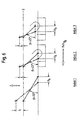
- FIG. 6 shows a schematic, greatly simplified schematic diagram of an essential partial area of a spreading device of a device according to the invention in accordance with a fourth embodiment.
- This variant is similar in its basic construction to the embodiment according to FIG. 4 and illustrates a case in which the dimensions of the device components used, ie here the lengths of the levers (lever 1, lever 2 and lever 3) and for example the arrangement and dimension of the pressure pieces and thus the position of the lever articulation points in relation to a starting position are different for each spreading area.
- the upper end points of all three levers lie at a common vertical height, which is indicated in FIG. 6 by a line "0".
- This example shows well that with a certain construction the length of the lever does not necessarily have to influence the angle ⁇ .
- Lever 3 is shorter than lever 2, but has the same angle ⁇ (here: 45 °).
- ⁇ 45 °
- different expansion strokes h can be achieved in the axial direction, as indicated in the drawing.
- a desired start of spreading and breaking in time or a different build-up of force with the same stroke H A can then be achieved by appropriate design of the lever length and corresponding angle ⁇ .
- the upper ends of the levers or the associated upper lever pivot points can, for example, be at a common height in an initial position (here: line "0"), while the respective lower lever ends or the associated lower lever pivot points can lie at different positions (compare levers 2 and lever 3).
- a corresponding configuration could, for example, also be used analogously for example 7 described above.
- the invention is not limited to the above embodiments, which is only the general explanation of the core idea serve the invention, limited. Within the scope of protection the device according to the invention can rather also others as the configurations described above.
- the wedge elements 18, 20 of the Spreading control device of FIG. 2 can also be used larger units can be summarized. Furthermore, it is possible the wedge elements 18 on both sides of the elongated actuator 16 and the wedge elements 20 to provide on both mandrel halves 12, 14. In the event of The use of crushing segments can also result in wedge surfaces be arranged on the inside of the crushing segments.
- the lever arms 42, 54, 56th basically also directly, for example via a Articulated connection with the actuating element 40 or the Crushing segment 38 may be connected.
Abstract
Description
Die Erfindung betrifft eine Vorrichtung zum Bruchtrennen
eines Werkstücks gemäß dem Oberbegriff des Anspruchs 1.The invention relates to a device for breaking separation
a workpiece according to the preamble of
Aus der US-P-4,684,267 bzw. der EP 0 167 320 B1 ist eine
Vorrichtung zum Bruchtrennen eines Werkstücks mit mehreren
axial fluchtend hintereinander angeordneten ringartigen
Werkstückabschnitten bekannt, wobei die Vorrichtung mit einer
Spreizeinrichtung versehen ist, die in eine durch einen
jeweiligen ringartigen Werkstückabschnitt gebildete Bohrung
axial einführbar und an mindestens zwei in Axialrichtung
voneinander beabstandeten Aufspreizbereichen aufspreizbar
ist. Die Spreizeinrichtung besitzt einen Spreizdorn, der mit
einer Vielzahl von bezogen auf die jeweilige Bohrung in einer
radialen Richtung bewegbaren Spreizsegmenten ausgestattet
ist, wobei jedes Spreizsegment einen Aufspreizbereich des
Spreizdorns bildet. Alle Spreizsegmente sind über ein
langgestrecktes Betätigungselement, das sich im Inneren des
Spreizdorns in Axialrichtung erstreckt und mit einem
außerhalb des Spreizdorns befindlichen Stellglied gekoppelt
ist, gemeinsam zu betätigen. Das Betätigungselement besitzt
eine Vielzahl von Keilelementen mit sich in Bezug auf die
Axialrichtung winkelig erstreckenden ersten Keilflächen, die
einer Vielzahl von jeweils an einem Innenabschnitt der
Spreizsegmente geformten und sich in Bezug auf die
Axialrichtung ebenfalls winkelig erstreckenden zweiten
Keilflächen komplementär zugeordnet sind. Wird das
Betätigungselement axial bewegt, so wirken die ersten und die
zweiten Keilflächen zusammen, wodurch die Spreizsegmente
ausgefahren und der Spreizdorn somit aufgespreizt wird. Mit
dieser Spreizeinrichtung können alle ringartigen
Werkstückabschnitte des Werkstückes gleichzeitig
bruchgetrennt werden.One is known from US Pat. No. 4,684,267 and
Vorrichtungen der zuvor beschriebenen Art besitzen jedoch einen Nachteil dahingehend, daß ihre Spreizeinrichtung auf eine einmal festgelegt Werkstückgeometrie, das heißt hier die Position der abzutrennenden ringartigen Werkstückabschnitte, festgelegt ist und nachträglich nicht oder nur mit erheblichem fertigungstechnischen Aufwand wieder geändert oder an ein andersartiges Werkstück angepaßt werden kann. Für ein anders gestaltetes Werkstück muß folglich auch eine andere Spreizeinrichtung verwendet werden, was mit nicht unerheblichen Kosten für die Herstellung dieser zusätzlichen Spreizeinrichtungen sowie ihrer Lagerhaltung und Wartung verbunden ist.However, devices of the type described above have a disadvantage in that their spreader on Once the workpiece geometry has been defined, this means that Position of the ring-like workpiece sections to be separated, is specified and subsequently not or only with considerable manufacturing effort changed again or can be adapted to a different type of workpiece. For a differently designed workpiece must therefore also have a other spreader can be used, what with not insignificant cost of making this additional Spreaders and their warehousing and maintenance connected is.
Der Erfindung liegt das technische Problem zugrunde eine gattungsgemäße Vorrichtung zu schaffen, die auf möglichst einfache und effektive Art und Weise an Werkstücke mit unterschiedlichen Positionen der abzutrennenden ringartigen Werkstückabschnitte anpaßbar ist.The invention is based on the technical problem Generic device to create the most possible simple and effective way to work with different positions of the ring-like to be separated Workpiece sections is customizable.
Das vorhergenannte technische Problem wird gelöst durch eine
erfindungsgemäße Vorrichtung mit den Merkmalen des
Anspruchs 1.The aforementioned technical problem is solved by a
Device according to the invention with the features of
Diese Vorrichtung zum Bruchtrennen eines Werkstücks mit mehreren axial fluchtend hintereinander angeordneten ringartigen Werkstückabschnitten verfügt über mindestens eine Spreizeinrichtung, die in eine durch einen jeweiligen ringartigen Werkstückabschnitt gebildete Bohrung axial einführbar ist und mindestens ein Spreizelement aufweist, daß an mindestens zwei in Axialrichtung voneinander beabstandeten Aufspreizbereichen aufspreizbar ist, wobei die Spreizeinrichtung mit einer mit dem mindestens einen Spreizelement zusammenwirkenden integrierten Aufspreizkontrolleinrichtung zum Kontrollieren einer variablen Position und/oder einer variablen Aufspreizweite und/oder eines variablen Aufspreizzeitpunktes und/oder einer variablen Aufspreizreihenfolge der mindestens zwei Aufspreizbereiche versehen ist.This device for breaking a workpiece with several axially aligned one behind the other ring-like workpiece sections has at least one Spreading device, which in one by a respective ring-like workpiece section formed axially is insertable and has at least one expansion element that on at least two spaced apart in the axial direction Spreading areas is spreadable, the Spreading device with one with the at least one Integrated expanding element interacting Spreading control device for controlling a variable position and / or a variable spreading width and / or a variable time of expansion and / or one variable spread order of the at least two Spreading areas is provided.
Als ein Werkstück mit mehreren axial fluchtend hintereinander angeordneten ringartigen Werkstückabschnitten ist im Sinne der Erfindung auch eine Werkstückanordnung zu verstehen, die mehrere aneinandergereihte einzelne Werkstücke mit jeweils nur einem einzigen ringartigen Werkstückabschnitt umfaßt. Des Weiteren auch eine Kombination aus dieser letztgenannten Werkstückanordnung und einem oder mehreren Werkstücken mit mehreren axial fluchtend hintereinander angeordneten ringartigen Werkstückabschnitten. Die integrierte Aufspreizkontrolleinrichtung ist vorzugsweise im wesentlichen rein mechanisch aufgebaut. Die Erfindung ist jedoch nicht ausschließlich auf diese Ausgestaltungsform fixiert. Die integrierte Aufspreizkontrolleinrichtung kann im Sinne der Erfindung ebenso auch hydraulische, pneumatische, elektromechanische, elektrische, elektronische und andere geeignete Komponenten sowie Mischformen daraus enthalten.As a workpiece with several axially aligned one behind the other arranged ring-like workpiece sections is in the sense the invention to understand a workpiece assembly that several individual workpieces lined up with each other comprises only a single ring-like workpiece section. Of Furthermore, a combination of the latter Workpiece arrangement and one or more workpieces with several axially aligned one behind the other ring-like workpiece sections. The integrated Spreading control device is preferably essentially constructed purely mechanically. However, the invention is not fixed exclusively on this design. The integrated spreading control device can in the sense of Invention also hydraulic, pneumatic, electromechanical, electrical, electronic and other suitable Components and mixed forms of it included.
Bei der erfindungsgemäßen Vorrichtung ist die Spreizeinrichtung aufgrund ihrer integrierten Aufspreizkontrolleinrichtung auf einfache und effektive Art und Weise an Werkstücke mit einer unterschiedlichen Anzahl und/oder unterschiedlichen Positionen und/oder unterschiedlichen Ausgestaltung der abzutrennenden ringartigen Werkstückabschnitte anpaßbar. Entgegen dem bisher bekannten Stand der Technik ist es bei der erfindungsgemäßen Vorrichtung daher für eine große Anzahl von Werkstückvarianten nicht erforderlich, eine separate Spreizeinrichtung herzustellen. Auch die Notwendigkeit einer entsprechenden Lagerhaltung und/oder Wartung entfällt. Die für die Anpassung an ein andersartig gestaltetes Werkstück erforderlichen Schritte sind bei der erfindungsgemäßen Vorrichtung infolge der integrierten Aufspreizkontrolleinrichtung leicht und mit einfachen Mittel durchführbar. Die Herstellungs- und Betriebskosten einer erfindungsgemäßen Vorrichtung können demzufolge gegenüber konventionellen Vorrichtung gesenkt werden. Auch läßt sich mit der erfindungsgemäßen Vorrichtung eine flexiblere Fertigung realisieren, was insbesondere bei kleineren Werkstückserien von großem Vorteil ist. Es ist jedoch auch noch besonders hervorzuheben, daß mittels der integrierten Aufspreizkontrolleinrichtung nicht nur die Position der Aufspreizbereiche der Spreizeinrichtung, sondern auch deren Aufspreizweite und/oder Aufspreizzeitpunkte und/oder Aufspreizreihenfolge variabel kontrolliert werden können, wodurch die Spreizeinrichtung multifunktionale Eigenschaften erhält und die Variationsmöglichkeiten bei der Bearbeitung von Werkstücken zusätzlich erhöht wird.In the device according to the invention Spreading device due to its integrated Spreading control device in a simple and effective way and way on workpieces with a different number and / or different positions and / or different design of the to be separated ring-like workpiece sections adaptable. Contrary to that so far known prior art, it is in the invention Device therefore for a large number of Workpiece variants not required, a separate one To produce spreading device. Also the need for one corresponding storage and / or maintenance is not necessary. The for adaptation to a differently designed workpiece necessary steps are in the inventive Device due to the integrated Spreading control device easily and with simple means feasible. The manufacturing and operating costs of one The device according to the invention can therefore be compared conventional device can be lowered. Also can be a more flexible with the device according to the invention Realize manufacturing, especially for smaller ones Workpiece series is of great advantage. However, it is also should be particularly emphasized that by means of the integrated Spreading control device not only the position of the Spreading areas of the spreader, but also their Spreading width and / or spreading times and / or Spreading order can be controlled variably, which makes the spreader multifunctional properties receives and the possible variations in processing of workpieces is additionally increased.
Weitere vorteilhafte Ausgestaltungsmerkmale der erfindungsgemäßen Vorrichtung sind Gegenstand der Unteransprüche.Further advantageous design features of the The device according to the invention are the subject of Dependent claims.
Bevorzugte Ausführungsbeispiele der Erfindung mit zusätzlichen Ausgestaltungsdetails und weiteren Vorteilen sind nachfolgend unter Bezugnahme auf die beigefügten Zeichnungen näher beschrieben und erläutert.Preferred embodiments of the invention with additional design details and other advantages are below with reference to the attached Drawings described and explained in more detail.
Es zeigt:
- Fig. 1
- eine schematische Querschnittsansicht eines mittels der erfindungsgemäßen Vorrichtung durch Bruchtrennen abzutrennenden ringartigen Werkstückabschnitts eines Werkstücks,
- Fig. 2
- eine schematische Querschnittsansicht durch eine Spreizeinrichtung einer erfindungsgemäßen Vorrichtung gemäß einer ersten Ausführungsform,
- Fig. 3
- eine schematische Frontalansicht der Spreizeinrichtung von Fig. 2,
- Fig. 4
- eine schematische Querschnittsansicht durch einen wesentlichen Teilbereich einer Spreizeinrichtung einer erfindungsgemäßen Vorrichtung gemäß einer zweiten Ausführungsform,
- Fig. 5
- eine schematische Querschnittsansicht durch einen wesentlichen Teilbereich einer Spreizeinrichtung einer erfindungsgemäßen Vorrichtung gemäß einer dritten Ausführungsform, und
- Fig. 6
- eine schematische, stark vereinfachte Prinzipskizze eines wesentlichen Teilbereichs einer Spreizeinrichtung einer erfindungsgemäßen Vorrichtung gemäß einer vierten Ausführungsform.
- Fig. 1
- 2 shows a schematic cross-sectional view of a ring-like workpiece section of a workpiece to be separated by fracture separation by means of the device according to the invention,
- Fig. 2
- 2 shows a schematic cross-sectional view through a spreading device of a device according to the invention in accordance with a first embodiment,
- Fig. 3
- 2 shows a schematic frontal view of the spreading device from FIG. 2,
- Fig. 4
- 2 shows a schematic cross-sectional view through an essential partial area of a spreading device of a device according to the invention in accordance with a second embodiment,
- Fig. 5
- 2 shows a schematic cross-sectional view through an essential partial area of a spreading device of a device according to the invention in accordance with a third embodiment, and
- Fig. 6
- a schematic, highly simplified schematic diagram of an essential portion of a spreading device of a device according to a fourth embodiment.
In der nachfolgenden Beschreibung und in den Figuren werden zur Vermeidung von Wiederholungen gleiche Bauteile und Komponenten auch mit gleichen Bezugszeichen gekennzeichnet, sofern keine weitere Differenzierung erforderlich ist.In the description below and in the figures To avoid repetitions, the same components and Components also identified with the same reference symbols, unless further differentiation is required.
Fig. 1 zeigt in einer schematische Querschnittsansicht einen
einzelnen ringartigen Werkstückabschnitt 4 eines Werkstücks
2, an dem mehrere axial fluchtend hintereinander angeordnete
ringartige Werkstückabschnitte 4 integral ausgebildet sind.
Für die nachfolgend beschriebenen Ausführungsbeispiele wird
angenommen, daß es sich bei dem Werkstück um einen
Gehäuseblock 2 mit mehreren axial fluchtend hintereinander
angeordneten ringartigen Werkstückabschnitten, im
nachfolgenden Lagerdeckel 4 genannt, handelt. Die Lagerdeckel
4 können hierbei in Axialrichtung A entweder gleichmäßig oder
aber ungleichmäßig voneinander beabstandet sein. Die
Lagerdeckel 4 umschließen jeweils eine Bohrung 6, die zur
Lagerung einer Kurbelwelle oder dergleichen dient. Diese
Lagerdeckel 4 sollen mittels der erfindungsgemäßen
Vorrichtung durch Bruchtrennen von dem Gehäuseblock 2 gelöst
werden, so daß sich an einer vorbestimmten Bruchebene eine
jeweils individuelle Makroverzahnung am Materialgefüge der
abgetrennten Lagerdeckel 4 und des verbleibenden
Gehäuseblocks 2 ausbildet und eine genau zusammenpassende
Paarung zwischen einem jeweiligen Lagerdeckel 4 und seinem
zugehörigen Gehäuseblockabschnitt entsteht. Die Bruchebene
wird im vorliegenden Fall durch zwei auf einer Innenfläche
6.2 einer jeweiligen Bohrung 6 befindliche Bruchkerben 8
festgelegt, die vor dem eigentlichen Bruchtrennvorgang
hergestellt werden.Fig. 1 shows a schematic cross-sectional view
individual ring-like workpiece section 4 of a
Die erfindungsgemäße Vorrichtung zum Bruchtrennen dieses
Werkstücks 2 umfaßt im vorliegenden Beispiel, wie in der
Fig. 2 in einer schematischen Querschnittsansicht gezeigt,
eine Spreizeinrichtung, die einen Spreizdorn 10 mit zwei
senkrecht zur Axialrichtung A, und damit in Bezug auf die
Bohrungen 6 in einer radialen Richtung, relativ zueinander
bewegliche Spreizdornhälften 12, 14 besitzt. Die in der Fig.
2 untere Spreizdornhälfte 12 ist hierbei eine feste
Spreizdornhälfte, während die in Fig. 2 obere
Spreizdornhälfte 14 eine bewegliche Spreizdornhälfte ist. Der
Spreizdorn 10 ist in die Bohrungen 6 (vergl. Fig. 1) axial
(A) einführbar und im Bereich eines jeweiligen Lagerdeckels 4
mit Hilfe eines der Übersichtlichkeit halber nicht
dargestellten Aktuators aufspreizbar. Die jeweiligen Bereiche
und/oder Umgebungen des eingeführten Spreizdorns 10, die
innerhalb der Bohrungen 6 zu liegen kommen, werden als
Aufspreizbereiche bezeichnet. Je nach Art der verwendeten
Spreizeinrichtung kann sich ein einzelner Aufspreizbereich
jedoch grundsätzlich auch axial über eine jeweilige Bohrung 6
hinaus erstrecken.The inventive device for breaking this
Der Spreizdorn 10 umfaßt des Weiteren eine zwischen den
Spreizdornhälften 12, 14 angeordnete und mit der beweglichen
Spreizdornhälfte 14 zusammenwirkende integrierte
Aufspreizkontrolleinrichtung zum Kontrollieren einer
variablen Position und/oder einer variablen Aufspreizweite
und/oder eines variablen Aufspreizzeitpunktes und/oder einer
variablen Aufspreizreihenfolge der Aufspreizbereiche des
Spreizdorns 10.The expanding
Diese Aufspreizkontrolleinrichtung umfaßt ein in
Axialrichtung A zwischen den Spreizdornhälften 12, 14
verlaufendes langgestrecktes Betätigungselement 16, im
nachfolgenden Zugstange 16 genannt, deren aus dem Spreizdorn
10 herausragendes Ende mit dem zuvor erwähnten Aktuator
koppelbar und mit dessen Hilfe in Axialrichtung bewegbar ist,
wie in der Zeichnung durch einen Doppelpfeil angedeutet. Die
Zugstange 16 besitzt auf ihrer der beweglichen
Spreizdornhälfte 14 zugewandten Längsseite eine Vielzahl von
integralen ersten Keilelementen 18 mit sich in Bezug auf die
Axialrichtung A winkelig (α) erstreckenden ersten
Keilflächen 18.2. Überdies verfügt die
Aufspreizkontrolleinrichtung über eine Vielzahl von auf der
Innenseite der beweglichen Spreizdornhälfte 14 lösbar
befestigten zweiten Keilelementen 20 mit sich in Bezug auf
die Axialrichtung A winkelig (α) erstreckenden zweiten
Keilflächen 20.2. Die zweiten Keilelemente 20 sind zu den
ersten Keilelementen 18 komplementär ausgebildet und diesen
zugeordnet. Obwohl die Geometrie und insbesondere der
Keilwinkel α der ersten und zweiten Keilelemente 18, 20 im
vorliegenden Ausführungsbeispiel gleich sind, können sie
jedoch auch unterschiedlich sein, wie nachfolgend noch
erläutert werden wird. This spreading control device comprises an in
Axial direction A between the mandrel halves 12, 14
extending
Der gegenseitige axiale Abstand DB1, DB2, ... DBX der zweiten
Keilelemente 20 ist variabel einstellbar. Zu diesem Zweck
sind die zweiten Keilelemente 20 mit Befestigungsmitteln 22
in einer Führungsnut 24 an der Innenseite der beweglichen
Spreizdornhälfte 14 lösbar und damit auch einzeln
auswechselbar fixiert. Die Befestigungsmitteln 22 sind so
ausgelegt, daß sie in jedem Fall die von der Zugstange 16
ausgehende und für den Aufspreizvorgang erforderliche
Axialkraft, die sich an einem Keilelementenpaar 18, 20 in
eine senkrecht zur Axialrichtung A verlaufende
Aufspreizkraft-Teilkomponente aufspaltet, sicher übertragen
können. Zu diesem Zweck können die zweiten Keilelemente 20
und/oder die bewegliche Spreizdornhälfte 14 mit zusätzlichen
lastübertragenden Elementen oder Widerlagern ausgestattet
sein, die in der Zeichnung der Übersichtlichkeit halber
jedoch nicht gezeigt sind.The mutual axial distance D B1 , D B2 , ... D BX of the
Anstelle oder zusätzlich zu den zweiten Keilelementen 20 der
beweglichen Spreizdornhälfte 14 können natürlich auch die
ersten Keilelemente 18 und/oder die Zugstange 16 derart
ausgestaltet sein, daß der gegenseitige axialer Abstand DA1,
DA2 ... DAX der ersten Keilelemente 18 auf der Zugstange 16 in
analoger oder anderer Weise variabel einstellbar ist.Instead of or in addition to the
Nachfolgend wird nun anhand einiger Beispiele die Funktion
und Wirkung der Aufspreizkontrolleinrichtung und ihrer
unterschiedlichen Varianten erläutert werden. Der Einfachheit
halber wird angenommen, daß die ersten und zweiten
Keilelemente 18, 20 jeweils gleichartig ausgestaltet sind.The following is the function using a few examples
and effect of the spreading control device and its
different variants are explained. The simplicity
it is assumed that the first and
Gegeben ist ein Gehäuseblock 2 mit gleichartigen, axial
gleichmäßig voneinander beabstandeten Lagerdeckeln 4. Die
zweiten Keilelemente 20 werden so fixiert, daß ihr
gegenseitiger axialer Abstand DB1, DB2, ... DBX jeweils gleich
ist und dem gegenseitigen axialen Abstand DA1, DA2... DAX der
ersten Keilelemente 18 der Zugstange 16 entspricht. Bei einer
Betätigung der Zugstange 16 werden alle Aufspreizbereiche des
Spreizdorns 10 gleichzeitig aufgespreizt und alle Lagerdeckel
4 gleichzeitig bruchgetrennt.There is a
Gegeben ist ein Gehäuseblock 2 mit gleichartigen, axial
gleichmäßig voneinander beabstandeten Lagerdeckeln 4. Die
Anordnung der ersten Keilelemente 18 ist wie in Beispiel 1.
Die zweiten Keilelemente 20 werden so fixiert, daß der
gegenseitige axiale Abstand zwischen den aufeinanderfolgenden
benachbarten zweiten Keilelementen 20 größer wird:
DBX > ..DB2 > DB1. Bei einer Betätigung der Zugstange 16 werden
die Aufspreizbereiche beginnend von der linken Seite in Fig.
2 nacheinander aufgespreizt und die Lagerdeckel 4
nacheinander bruchgetrennt. Falls DB1 > DB2 ...> DBX, würde das
Aufspreizen und Bruchtrennen dagegen von der rechten Seite in
Fig. 2 her beginnen. Diese Varianten sind besonders dann von
Vorteil, wenn eine große Anzahl von abzutrennenden
Werkstückabschnitten 4 vorliegt und/oder die Bruchtrennkraft
gering gehalten werden soll.There is a
Da bei diesem Beispiel die Keilelemente 18, 20 nacheinander
zum Eingriff kommen, können Sie in dem jeweils aktivierten
Aufspreizbereich (sowie eventuell auch an den daran
angrenzenden Aufspreizbereichen), insbesondere, wenn die
Aufspreizbereiche in Axialrichtung A eng beieinander liegen,
eine gewisse Schrägstellung oder Verkantung der beweglichen
Spreizdornhälfte 14 bewirkten, da der Spreizhub unter
Umständen einseitig beginnt. Dies würde zu Biegemomenten in
dem Spreizdorn führen, was sich nachteilig auswirken könnte.
Wie in Fig. 2 angedeutet, ist die bewegliche Spreizdornhälfte
14 daher in beweglich miteinander verbundene
Spreizdornhälftenabschnitte 14A, 14B, 14C unterteilt, wobei
jeder dieser Spreizdornhälftenabschnitte 14A, 14B, 14C einem
jeweils zugehörigen Aufspreizbereich zugeordnet ist. Die
Spreizdornhälftenabschnitte 14A, 14B, 14C sind über eine
flexible Verbindung 58 und/oder eine Kupplungsverbindung
und/oder eine Einfach- und/oder Mehrfachgelenkverbindung oder
dergleichen miteinander verbunden, so daß die jeweiligen
Aufspreizbereiche unabhängig voneinander aufspreizbar sind
und eine Schrägstellung oder ein Verkanten der beweglichen
Spreizdornhälfte 14 sowie ein daraus resultierendes
unerwünschtes Biegemoment wirkungsvoll vermieden werden kann.
Es ist im Sinne der Erfindung denkbar, unter Berücksichtigung
von gewissen konstruktiven Änderungen auch die feste
Spreizdornhälfte 12 mit entsprechenden
Spreizdornhälftenabschnitten auszustatten. Die zuvor
erläuterte Ausgestaltungsweise kann grundsätzlich auch bei
den Varianten gemäß den nachstehenden Beispielen 3 und 4
Anwendung finden.Since in this example the
Gegeben ist ein Gehäuseblock 2 mit gleichartigen, axial
unterschiedlich voneinander beabstandeten Lagerdeckeln 4. Die
ersten Keilelemente 18 auf der Zugstange 16 und die zweiten
Keilelemente 20 der beweglichen Spreizdornhälfte 14 werden in
ihrer Position so axial versetzt und dann relativ zueinander
fixiert, daß sie ähnlich wie in Beispiel 1 miteinander
korrespondieren, wobei DA1 = DB1, DA2 = DB2 ... DAX = DBX. Bei
Betätigung der Zugstange 16 kann wiederum ein gleichzeitiges
Aufspreizen und Bruchtrennen der Lagerdeckel 4 erzielt
werden. Vergrößert man hingegen den gegenseitigen axialen
Abstand zwischen aufeinanderfolgenden benachbarten ersten
Keilelementen 18 und/oder aufeinanderfolgenden benachbarten
zweiten Keilelementen 20, so kann ähnlich wie in Beispiel 2
wiederum ein aufeinanderfolgendes Aufspreizen und
Bruchtrennen realisiert werden. Given is a
Gegeben ist ein Gehäuseblock 2 mit gleichartigen, axial
gleichmäßig voneinander beabstandeten Lagerdeckeln 4. Die
Abstände DA1, DA2... DAX seien wie in Beispiel 1 fest
vorgegeben. Die Abstände zwischen den zweiten Keilelementen
ist unterschiedlich eingestellt: DB1 ≠ ..DB2 ≠ DBX. Bei
Betätigung der Zugstange 16 wird eine unterschiedliche, aber
durch die Wahl der Abstände DB1, DB2... DBX genau festlegbare
Reihenfolge beim Aufspreizen und Bruchtrennen der jeweiligen
Lagerdeckel 4 erzielt.Given a
Es ist ersichtlich, daß die zuvor beschriebenen Beispiele 1 bis 4 in vielfältiger Weise abgeändert und/oder kombiniert werden können. Werden für einen oder mehrere Aufspreizbereiche jeweils einander zugeordnete erste und zweite Keilelementenpaare 18, 20 verwendet, die sich hinsichtlich ihrer Geometrie, insbesondere ihrer Keilwinkel α, von der Geometrie der anderen Keilelementenpaare der Spreizeinrichtung unterscheiden, so kann beispielsweise auch die jeweilige Aufspreizweite und die Aufspreizkraft eines oder mehrerer Aufspreizbereiche individuell eingestellt werden. Dies ist besonders bei Werkstücken mit unterschiedlich geformten oder unterschiedlich dimensionierten ringartigen Werkstückabschnitten von Vorteil.It can be seen that Examples 1 described above to 4 modified and / or combined in many ways can be. Be for one or more Spreading areas each associated with the first and second wedge element pairs 18, 20 are used, the with regard to their geometry, in particular their wedge angle α, on the geometry of the other wedge element pairs Differentiate spreading device, for example the respective spreading width and the spreading force of a or several spreading areas individually set become. This is particularly the case with workpieces differently shaped or different dimensioned ring-like workpiece sections is an advantage.
Durch ihre integrierte Aufspreizkontrolleinrichtung ermöglicht es die zuvor beschriebene Spreizeinrichtung also auf multifunktionale Art und Weise eine variable Position und/oder eine variable Aufspreizweite und/oder einen variablen Aufspreizzeitpunkt und/oder eine variable Aufspreizreihenfolge und/oder eine variable Aufspreizkraft der Aufspreizbereiche einfach und zuverlässig zu kontrollieren.Thanks to its integrated spreading control device the spreading device described above thus makes it possible a variable position in a multifunctional way and / or a variable spreading width and / or a variable time of expansion and / or a variable Spread order and / or a variable spreading force the spreading areas easily and reliably check.
Fig. 3 zeigt eine schematische Frontalansicht der
Spreizeinrichtung von Fig. 2. Wie aus den Fig. 2 und 3
ersichtlich, ist der Spreizdorn 10 an einem bezogen auf die
axiale Einführrichtung A vorderen Abschnitt mit einer als
Räumeinrichtung 26 ausgebildeten Trenneinrichtung zum
Herstellen von jeweils zwei Bruchkerben 8, 8 in einer
jeweiligen Bohrung 6 (vergl. Fig. 1) während des Einführens
der Spreizeinrichtung 10 ausgestattet.
Diese Trenn- bzw. Räumeinrichtung 26 ist nicht mit den für
das eigentliche Bruchtrennen des Werkstücks 2 vorgesehenen
Mitteln zu verwechseln; sie hat im vorliegenden Fall eine
ausschließlich spanabhebende, formgebende Funktion zur
Bearbeitung der Innenflächen 6.2 der Bohrungen 6. Wie
besonders gut in Fig. 3 erkennbar ist, besitzt die
Räumeinrichtung 26 zwei einander diametral gegenüberliegende
Räumwerkzeuge 28, deren Schneiden leicht radial über den
Außenumfang des Spreizdorn 10 überstehen. Während des
Einführens des Spreizdorns 10 in die Bohrungen 6 des
Gehäuseblocks 2 werden folglich jeweils zwei diametral
gegenüberliegende Bruchkerben 8, 8 in der inneren
Umfangsfläche 6.2 einer jeweiligen Bohrung 6 ausgeräumt
(vergl. Fig. 1). Wenn der Spreizdorn 10 beim Einführvorgang
weiter in axialer Richtung A durch die Bohrungen 6
voranschreitet, werden in einer Bohrung 6 nach der anderen
die Bruchkerben 8, 8 hergestellt, bis alle Bohrungen 6 des
Gehäuseblocks 2 mit den jeweils zwei Bruchkerben 8, 8
versehen sind. Im vollständig eingeführten Zustand ragt das
mit den Räumwerkzeugen 28 versehene Ende des Spreizdorns 10
aus der zuletzt geräumten Bohrung 6 heraus, so daß die
Räumwerkzeuge 28 beim nachfolgenden Bruchtrennvorgang den
Spreizdorn 10 nicht behindern. Nach dem Bruchtrennen kann der
Spreizdorn 10 infolge der abgetrennten Lagerdeckel 4 sowie
der üblicherweise in Verbindung mit dem Werkstück 2
verwendeten verstellbaren Werkstückhalterungen, die hier
nicht näher beschrieben werden sollen, trotz der
Räumwerkzeuge 28 wieder leicht aus dem Werkstück 2 entfernt
werden. 3 shows a schematic frontal view of the spreading device from FIG. 2. As can be seen from FIGS. 2 and 3, the expanding
This separating or
Fig. 4 zeigt eine schematische Querschnittsansicht durch
einen wesentlichen Teilbereich einer Spreizeinrichtung einer
erfindungsgemäßen Vorrichtung gemäß einer zweiten
Ausführungsform. Die Spreizeinrichtung umfaßt einen
Spreizdorn 30, von dem in der Figur ausschnittsweise die
Umgebung eines einzelnen Aufspreizbereiches dargestellt ist.
Der Spreizdorn 30 besitzt wiederum zwei Spreizdornhälften 32,
34. Die erste Spreizdornhälfte 32 ist in ihrer
Längserstreckung durchgehend ausgebildet. Die zweite
Spreizdornhälfte 34 besitzt in Axialrichtung A voneinander
beabstandete Führungsstücke 36, die an der ersten
Spreizdornhälfte 32 fixiert sind. Zwischen benachbarten
Führungsstücken 36 ist jeweils ein in seiner Außenkontur im
wesentlichen halbkreisförmiges, bewegliches Brechsegment 38
eingefügt, wobei ein jeweiliges Brechsegment 38 hinsichtlich
seiner Anordnung und Funktion einem jeweiligen Lagerdeckel 4
des durch Bruchtrennen zu bearbeitenden Gehäuseblocks 2
zugeordnet ist. Die Anzahl der Brechsegmente 38 entspricht
der Anzahl der abzutrennenden Lagerdeckel 4. Die
Brechsegmente 38 sind mittels eines zwischen den beiden
Brechdornhälften 32, 34 außermittig verlaufenden und in
Axialrichtung A beweglichen langgestreckten Brechsegment-Betätigungselementes
40 relativ zu der ersten
Spreizdornhälfte 32 senkrecht zur Lagerachse A (und damit
bezogen of die Bohrung 6 in einer radialen Richtung)
ausfahrbar. Mittels eines Brechsegmentes 38 kann somit die
Aufspreizwirkung des Spreizdorns 30 an einem jeweiligen
Lagerdeckel 4 (in der Figur ebenfalls eingezeichnet) erzielt
und eine Brechkraft ausgeübt werden.Fig. 4 shows a schematic cross-sectional view through
an essential portion of a spreading device
Device according to the invention according to a second
Embodiment. The spreader includes one
Expanding
Der Spreizdorn 30 von Fig. 4 ist mit einer
Aufspreizkontrolleinrichtung ausgestattet, die mit den
Brechsegmenten 38 zusammenwirkt. Die
Aufspreizkontrolleinrichtung umfaßt eine Vielzahl von in
Axialrichtung A voneinander beabstandeten Hebelelementen 42,
nachfolgend kurz Hebel 42 genannt, die jeweils in einem durch
ein jeweiliges Brechsegment 38 festgelegten Aufspreizbereich
zwischen den beiden Spreizdornhälften 32, 34 angeordnet sind
und sich in einem stumpfen Winkel β quer zur Axialrichtung A
erstrecken. Jedem Aufspreizbereich ist hier also ein Hebel 42
zugeordnet. Da die Komponenten der
Aufspreizkontrolleinrichtung im vorliegenden Fall für jeden
Aufspreizbereich gleich sind, wird nachfolgend nur ein
einzelner Aufspreizbereich betrachtet werden. Eine weiteres
Teilelement der Aufspreizkontrolleinrichtung bildet das
bereits zuvor erwähnte, in Axialrichtung A zwischen den
beiden Spreizdornhälften 32, 34 verlaufende Brechsegment-Betätigungselement
40, im nachfolgenden kurz
Betätigungselement 40 genannt. Es ist im vorliegenden Fall
indirekt mit einem Endbereich eines jeweiligen Hebels 42,
d.h. in der Fig. 4 mit dem unteren Ende 42.2 des gezeigten
Hebels 42, verbunden und wirkt mit diesem zusammen. Die
indirekte Verbindung erfolgt über ein mit dem
Betätigungselement 40 verbundenes Gleitstück 44, daß an dem
Betätigungselement 40 fixiert ist und zusammen mit diesem in
einem sich axial über den Aufspreizbereich hinaus
erstreckenden Hohlraum 46 beweglich geführt ist. Das
Gleitstück 44 besitzt eine Hebelendaufnahme 48, in der das
untere Hebelende 42.2 gelenkartig aufgenommen ist.The expanding
Die Aufspreizkontrolleinrichtung umfaßt ferner jeweils ein in
einem jeweiligen Aufspreizbereich, das heißt hier im Bereich
eines jeweiligen Brechsegmentes 38, angeordnetes und mit
diesem in direkter Wirkverbindung stehendes Hebel-Widerlager
50. Das Hebel-Widerlager ist als sog. Druckstück 50
ausgebildet, das auf seiner zum Hohlraum 46 weisenden Seite
mit einer Hebelendaufnahme 52 versehen ist, die der
Hebelendaufnahme 48 des Gleitstücks 44 ähnelt. In der
Hebelendaufnahme 52 des Druckstücks 50 ist das andere Ende
42.4 des Hebels 42 (in der Fig. 4 das obere Ende) gelenkartig
aufgenommen. In axialer Richtung A ist das Druckstück 50
zwischen zwei benachbarten Führungsstücken 36 gesichert, die
auch ein jeweiliges Brechsegment 38 zwischen sich aufnehmen.
In einer im wesentlichen senkrecht zur Axialrichtung A
verlaufenden Richtung ist das Druckstück 50 jedoch
entsprechend dem Brechsegment 38 beweglich. Die dem Hohlraum
46 abgewandte Seite des Druckstückes 50 stützt sich hierbei
auf der zum Hohlraum 46 weisenden Innenseite des
Brechsegmentes 38 ab.The spreading control device further comprises an in
a respective spreading area, that is here in the area
of a respective crushing
Bei einer axialen Bewegung des Betätigungselementes 40 in
einer in der Fig. 4 nach links gerichteten Richtung, wird das
untere Hebelende 42.2 über das Gleitstück 44 von dem
Betätigungselement 40 mitgenommen und aufgrund der
stumpfwinkeligen Anordnung β des Hebels 42 in Bezug auf die
Axialrichtung A und infolge der Abstützung des oberen
Hebelendes 42.4 in dem Druckstück 50 eine starke Übersetzung
mit einer senkrecht zur Axialrichtung A gerichteten
Brechkraftkomponente erzielt, welche das Brechsegment 38 über
das Druckstück 50 nach außen drückt und somit eine
Aufspreizwirkung erzielt. Dieser Vorgang verläuft an den
anderen Hebeln 42 und Brechsegmenten 38 des Spreizdorns 30
analog ab.With an axial movement of the
Die Anordnung eines jeweiligen Hebels 42 der
Aufspreizkontrolleinrichtung, insbesondere aber die Größe des
stumpfen Winkels β, ist entweder fest vorgegeben oder aber
individuell einstellbar. Eine Einstellbarkeit kann im Sinne
der Erfindung durch unterschiedliche Vorrichtungsmerkmale
gewährleistet werden, die in der Mehrzahl in der Fig. 4
erkennbar sind. So kann die Winkelstellung β des Hebels 42
beispielsweise durch den in Axialrichtung A gemessenen
Versatz der Hebelendaufnahmen 48, 52, der axialen und/oder
vertikalen Abmessung bzw. Anordnung des Gleitstücks 44
und/oder des Druckstücks 50 und/oder der axialen und/oder
vertikalen Position und/oder Ausgestaltung der
Gleitstück/Betätigungselementverbindung bzw. allgemein durch
die axiale und/oder vertikale Position der Hebelgelenke bzw.
der Hebelangriffspunkte beeinflußt werden. Sogar die Länge L
des Hebels 42 wird, eine ausreichende axiale Beweglichkeit
des Betätigungselementes 40 bzw. des Gleitstückes 44
vorausgesetzt, bei anderen fest vorgegebenen
Vorrichtungsdimensionen die Winkelstellung β beeinflussen. So
wird ein längerer Hebel 42 in einem nicht aufgespreizten
Ausgangszustand des Spreizdorns 30 einen kleinere Winkel β
und ein kürzerer Hebel 42 einen größeren Winkel β besitzen.
Je nach Anordnung und Ausgestaltung des Hebels 42, des
Gleitstücks 44, des Druckstücks 50 bzw. des
Betätigungselementes 40 oder etwaiger zwischengeschalteter
Zusatzkomponenten kann also das Aufspreizverhalten des
Spreizdorns 30 gezielt kontrolliert werden.The arrangement of a
Dies wird anhand folgender Beispiele verdeutlicht. Die
Anordnung und Ausbildung des Betätigungselementes 40, des
Gleitstücks 44, des Druckstücks 50, der Brechsegmente 38 und
der Führungsstücke 36 sei in jedem Fall gleich. Zu bearbeiten
sei ein Gehäuseblock 2 mit einer den Brechsegmenten 38 des
Spreizdorns 30 entsprechenden Anzahl und Anordnung von
gleichartigen Lagerdeckeln 4.The following examples illustrate this. The
Arrangement and design of the
Die Länge L der Hebel 42 ist für alle Aufspreizbereiche
gleich. Folglich ist auch der Stumpfe Winkel β für alle Hebel
42 gleich. Bei einer Aktivierung des Betätigungselementes 40
werden folglich alle Brechsegmente 38 gleichzeitig und
hinsichtlich ihrer Aufspreizweite bzw. ihres Spreizhubs
gleichmäßig ausfahren, jeweils eine im wesentlichen
gleichgroße Aufspreizkraft auf die Lagerdeckel 4 ausüben und
eine gleichzeitige Bruchtrennung aller Lagerdeckel 4
bewirken.The length L of the
Die Länge L der Hebel 42 ist unterschiedlich und wird
ausgehend von dem freien Ende des Spreizdorns 30 und bezogen
auf jeweils benachbarte Aufspreizbereiche gleichmäßig länger.
Folglich wird der jeweilige stumpfe Winkel β der Hebel 42
ausgehend von dem freien Ende immer kleiner. Bei einer
Aktivierung des Betätigungselementes 40 werden daher die
Brechsegmente 38 ausgehend von dem freien Ende nacheinander
ausfahren und die Lagerdeckel 4 nacheinander bruchtrennen.
Der erste Bruch erfolgt hierbei an dem Hebel mit dem in der
Ausgangsposition größten stumpfen Winkel β, da dieser als
erster die erforderliche Bruchkraft aufbringt (das Erreichen
eines hinreichenden Spreizhubs wird vorausgesetzt).The length L of the
Die Länge L der Hebel 42 und ihre Winkelanordnung und
Winkelverteilung über den gesamten Spreizdorn 30 hinweg sind
für jedes Brechsegment 38 unterschiedlich. Bei einer
Aktivierung des Betätigungselementes 40 werden die
Brechsegmente 38 beginnend bei dem kürzesten Hebel (mit dem
größten stumpfen Winkel β; das Erreichen eines hinreichenden
Spreizhubs wird vorausgesetzt) in unterschiedlicher, aber
durch die jeweiligen Winkel β genau festlegbaren Reihenfolge
ausgefahren und folglich die Lagerdeckel 4 in einer
unterschiedlichen, aber festgelegten Reihenfolge
bruchtrennen.The length L of the
Es ist ersichtlich, daß die zuvor beschriebenen Beispiele 5
bis 7 in vielfältiger Weise abgeändert und/oder kombiniert
werden können. Es wird darauf hingewiesen, daß sich die in
den Beispielen 6 und 7 beschriebenen Ergebnisse
selbstverständlich auch mit Hebeln 42 gleicher Länge L
erzielen lassen, wobei jedoch die jeweilige Winkelstellung β
der Hebel 42 für das Aufspreizkontrollverhalten wesentlich
ist; Bei jeweils gleicher Hebellänge L könnte eine
unterschiedliche Winkelstellung β beispielsweise durch
Gleitstücke 44 mit unterschiedlichen axialen Längen und/oder
vertikalen Abmessungen oder durch unterschiedlich voneinander
beabstandete axiale und/oder vertikale Angriffspunkte der
Gleitstücke 44 an dem Betätigungselement 40 und dergleichen
erreicht werden. It can be seen that Examples 5 described above
to 7 modified and / or combined in many ways
can be. It should be noted that the in
the results described in Examples 6 and 7
of course also with
Fig. 5 zeigt eine schematische Querschnittsansicht durch eine
Spreizeinrichtung einer erfindungsgemäßen Vorrichtung gemäß
einer dritten Ausführungsform. Die Aufspreizkontrolleinrichtung
dieser Variante verwendet ebenfalls das in Fig. 4
dargestellte Konstruktionsprinzip. Davon abweichend verläuft
das Betätigungselement 40 jedoch im wesentlichen mittig in
dem Spreizdorn 30. Des weiteren sind jedem Aufspreizbereich,
d.h. hier jedem Brechsegment 38, jeweils zwei Hebel 54, 56
zugeordnet sind, die bezogen auf die in Axialrichtung A
verlaufende Mittellinie des Spreizdorns 30 spiegelverkehrt
zueinander angeordnet sind und ein Hebelpaar bilden, zwischen
dem das Betätigungselement 40 verläuft. Die stumpfen Winkel
β1, β2 der Hebel 54, 56 sind im vorliegenden Beispiel gleich
groß. Es sind jedoch auch Anwendungen denkbar, bei denen die
stumpfen Winkel β1, β2 voneinander verschieden sind.5 shows a schematic cross-sectional view through a spreading device of a device according to the invention in accordance with a third embodiment. The spreading control device of this variant also uses the construction principle shown in FIG. 4. Deviating from this, however, the
Die zu dem Betätigungselement 40 weisenden Enden 54.2, 56.2
des Hebelpaares 54, 56 sind über ein am Betätigungselement 40
fixiertes Gleitstück 44, das zwei einander gegenüberliegende
seitliche Hebelendaufnahmen 48, 48 besitzt und mit dem
Betätigungselement 40 axial mitbewegbar ist, indirekt mit dem
Betätigungselement 40 verbunden und wirken mit diesem
zusammen. Die anderen Enden 54.4, 56.4 der beiden Hebel 54,
56 stützen sich jeweils in einem einer jeweiligen
Spreizdornhälfte 32, 34 zugeordneten Druckstück 50, 50 ab,
wobei das in der Fig. 5 untere Druckstück 50, wie in der
Ausführungsform von Fig. 4, wiederum mit dem Brechsegment 38
zusammenwirkt.The ends 54.2, 56.2 facing the
Mit der in Fig. 5 gezeigten Aufspreizkontrolleinrichtung sind ebenfalls die bereits in Zusammenhang mit der Fig. 4 beschriebenen Effekte und Kontrollmöglichkeiten erzielbar. Gegenüber der Variante von Fig. 4 ermöglicht das Ausführungsbeispiel gemäß Fig. 4 jedoch noch geringere axiale Abmessungen sowie aufgrund der Hebelpaaranordnung mit ihren Winkeln β1, β2 eine größere Anzahl von Variationsmöglichkeiten.With the spreading control device shown in FIG likewise those already in connection with FIG. 4 effects and control options described can be achieved. Compared to the variant of FIG. 4, this enables Embodiment according to FIG. 4, however, even smaller axial Dimensions and due to the lever pair arrangement with their Angles β1, β2 a larger number of Variations.
Fig. 6 zeigt eine schematische, stark vereinfachte
Prinzipskizze eines wesentlichen Teilbereichs einer
Spreizeinrichtung einer erfindungsgemäßen Vorrichtung gemäß
einer vierten Ausführungsform. Diese Variante ähnelt von
ihrer Grundkonstruktion her der Ausführungsform nach Fig. 4
und verdeutlicht einen Fall, bei dem die Dimensionen der
verwendeten Vorrichtungskomponenten, d.h. hier die Längen der
Hebel (Hebel 1, Hebel 2 und Hebel 3) sowie z.B. die Anordnung
und Abmessung der Druckstücke und damit auch die Lage der
Hebelgelenkpunkte bezogen auf eine Ausgangslage für jeden
Aufspreizbereich unterschiedlich sind. In der unbetätigten
Ausgangslage liegen die oberen Endpunkte aller drei Hebel auf
einer gemeinsamen vertikalen Höhe, die in der Fig. 6 durch
eine Linie "0" angedeutet ist. Dieses Beispiel zeigt gut, daß
bei einer bestimmten Konstruktionsweise die Länge des Hebels
nicht zwangsweise den Winkel β beeinflussen muß. Hebel 3 ist
kürzer als Hebel 2, hat aber den gleichen Winkel β (hier:
45°). Grundsätzlich können in der Variante nach Fig. 4 bei
einem für alle Hebel gleichen Hub HA des Brechsegment-Betätigungselementes
in Axialrichtung verschiedene Spreizhübe
h erreicht werden, wie in der Zeichnung angedeutet. In der
Regel wird es aber erwünscht sein, daß der Spreizhub h an
jeder Stelle bzw. an jedem Brechsegment gleich groß ist, da
dies eine einfachere Vorrichtungskonstruktion erlaubt. Ein
gewünschter zeitlicher Spreiz- und Bruchbeginn bzw. ein
unterschiedlicher Kraftaufbau bei gleichem Hub HA kann dann
durch eine entsprechende Auslegung von Hebellänge und
entsprechendem Winkel β erreicht werden. Die oberen Enden der
Hebel bzw. die zugehörigen oberen Hebelgelenkpunkte können
hierbei z.B. in einer Ausgangslage auf einer gemeinsamen Höhe
liegen (hier: Linie "0"), während die jeweiligen unteren
Hebelenden bzw. die zugehörigen unteren Hebelgelenkpunkte an
unterschiedlichen Positionen liegen können (vergleiche Hebel
2 und Hebel 3). Eine entsprechende Konfiguration könnte
beispielsweise auch analog für das oben geschilderte Beispiel
7 verwendet werden.6 shows a schematic, greatly simplified schematic diagram of an essential partial area of a spreading device of a device according to the invention in accordance with a fourth embodiment. This variant is similar in its basic construction to the embodiment according to FIG. 4 and illustrates a case in which the dimensions of the device components used, ie here the lengths of the levers (
Die Erfindung ist nicht auf die obigen Ausführungsbeispiele,
die lediglich der allgemeinen Erläuterung des Kerngedankens
der Erfindung dienen, beschränkt. Im Rahmen des Schutzumfangs
kann die erfindungsgemäße Vorrichtung vielmehr auch andere
als die oben beschriebenen Ausgestaltungsformen annehmen.
Die Keilelemente 18, 20 der
Aufspreizkontrolleinrichtung von Fig. 2 können auch zu
größeren Einheiten zusammengefaßt sein. Ferner ist es
möglich, die Keilelemente 18 auf beiden Seiten des
langgestreckten Betätigungselementes 16 und die Keilelemente
20 auf beiden Spreizdornhälften 12, 14 vorzusehen. Im Falle
der Verwendung von Brechsegmenten können Keilflächen auch auf
der Innenseite der Brechsegmente angeordnet sein. Bei den
Varianten nach Fig. 4 und 5 können die Hebelarme 42, 54, 56
grundsätzlich auch direkt, zum Beispiel über eine
Gelenkverbindung mit dem Betätigungselement 40 bzw. dem
Brechsegment 38 verbunden sein. Dies ist jedoch nur bei
geringeren Brechkräften bzw. einer sehr stabilen
Dimensionierung der einzelnen Bauteile und Gelenke sinnvoll.
Bei Bedarf können pro Aufspreizbereich auch mehrere
Einzelhebel, zum Beispiel in einer Parallelhebelanordnung,
oder mehrere Hebelpaare oder komplexere Hebelmechanismen
vorgesehen sein. Auch kann die Hebelgeometrie und -anordnung
von den obigen Beispielen abweichen. Anstelle eines einzelnen
Betätigungselementes 16, 40 sind auch mehrere
Betätigungselemente denkbar, welche die Komponenten der
Aufspreizkontrolleinrichtung bzw. der Spreizelemente einzeln
und/oder in Gruppen betätigen. The invention is not limited to the above embodiments,
which is only the general explanation of the core idea
serve the invention, limited. Within the scope of protection
the device according to the invention can rather also others
as the configurations described above.
The
Bezugszeichen in den Ansprüchen, der Beschreibung und den Zeichnungen dienen lediglich dem besseren Verständnis der Erfindung und sollen den Schutzumfang nicht einschränken. Reference signs in the claims, the description and the Drawings are only for a better understanding of the Invention and are not intended to limit the scope.
Es bezeichnen:
- 2
- Werkstück / Gehäuseblock
- 4
- Ringartige Werkstückabschnitte / Lagerdeckel
- 6
- Bohrung in 4
- 6.2
Innenfläche von 6- 8
- Bruchkerben
- 10
- Spreizdorn
- 12
Spreizdornhälfte von 10- 14
- Spreizdornhälfte (bewegliche -)
von 10 - 14A
- Spreizdornhälftenabschnitt
- 14B
- Spreizdornhälftenabschnitt
- 14C
- Spreizdornhälftenabschnitt
- 16
- Betätigungselement / Zugstange
- 18
- Erste Keilelemente
- 18.2
- Erste Keilflächen
- 20
- Zweite Keilelemente
- 20.2
- Zweite Keilflächen
- 22
- Befestigungsmittel
- 24
- Führungsnut in 14
- 26
- Trenneinrichtung / Räumeinrichtung
- 28
Räumwerkzeuge von 26- 30
- Spreizdorn
- 32
Erste Spreizdornhälfte von 30- 34
Zweite Spreizdornhälfte von 30- 36
- Führungsstücke
- 38
Brechsegmente von 30- 40
- Brechsegment-
Betätigungselement von 30 - 42
- Hebelelemente / Hebel
- 42.2
Oberes Ende von 42- 42.4
Unteres Ende von 42- 44
- Gleitstück
- 46
- Hohlraum
- 48
Hebelendaufnahme von 44- 50
- Hebel-Widerlager / Druckstück
- 52
Hebelendaufnahme von 50- 54
- Hebel
- 56
- Hebel
- 58
- flexible bzw. bewegliche Verbindung
- α
- Keilwinkel
- β1
- Stumpfer Winkel
- β2
- Stumpfer Winkel
- A
- Axialrichtung
- h
- Spreizhub eines Hebels bzw. eines Brechsegmentes
- HA
Hub von 40 in Axialrichtung
- 2
- Workpiece / housing block
- 4
- Ring-like workpiece sections / bearing caps
- 6
- Hole in 4th
- 6.2
- Inner surface of 6
- 8th
- breaking notches
- 10
- expanding mandrel
- 12
- Expanding mandrel half of 10
- 14
- Expanding mandrel half (movable -) of 10
- 14A
- Spreizdornhälftenabschnitt
- 14B
- Spreizdornhälftenabschnitt
- 14C
- Spreizdornhälftenabschnitt
- 16
- Actuator / pull rod
- 18
- First wedge elements
- 18.2
- First wedge surfaces
- 20
- Second wedge elements
- 20.2
- Second wedge surfaces
- 22
- fastener
- 24
- Guide groove in 14
- 26
- Separating device / clearing device
- 28
- Broaching tools from 26
- 30
- expanding mandrel
- 32
- First expanding mandrel half of 30
- 34
- Second expanding mandrel half of 30
- 36
- guide pieces
- 38
- Crushing segments of 30
- 40
- Crush segment actuator from 30
- 42
- Lever elements / levers
- 42.2
- Upper end of 42
- 42.4
- Lower end of 42
- 44
- slide
- 46
- cavity
- 48
- Lever end mount of 44
- 50
- Lever abutment / thrust piece
- 52
- Lever end mount of 50
- 54
- lever
- 56
- lever
- 58
- flexible or mobile connection
- α
- wedge angle
- β 1
- Obtuse angle
- β 2
- Obtuse angle
- A
- axially
- H
- Spread stroke of a lever or a crushing segment
- H A
- Stroke of 40 in the axial direction
Claims (17)
- Apparatus for the fracture separation of a work piece (2) with several ring-like work piece sections (4) arranged one behind the other in axial alignment, with at least one expanding device (10, 30) which can be introduced axially (A) into a bore (6) formed by a respective ring-like work piece section (4) and comprises at least one expanding element (14, 38) which is expandable in at least two expanding regions spaced apart from each other in the axial direction (A), characterised in that the expanding device (10, 30) is provided with an integrated expansion control device (16, 18, 20, 22; 40, 42, 44, 46, 48, 50, 52; ; ; 1; 2) cooperating with the at least one expanding element (14, 38), and this integrated expansion control device is selected from among a group of integrated expansion control devices including:an integrated expansion control device for controlling a variable position of the at least two expanding regions,an integrated expansion control device for controlling a variable expansion width of the at least two expanding regions,an integrated expansion control device for controlling a variable moment of expansion of the at least two expanding regions,an integrated expansion control device for controlling a variable sequence of expansion of the at least two expanding regions,an integrated expansion control device which presents a combination of two or more of the above-mentioned integrated expansion control devices.
- Apparatus according to claim 1, characterised in that the expanding device has at least one expansion mandrel (10, 30) with two expansion mandrel halves (12, 14; 32, 34) at least one of which has the expanding regions (38) spaced apart from each other in the axial direction (A), and in that the expansion control device (16, 18, 20, 22; 40, 42, 44, 46, 48, 50, 52; ; ; 1; 2) is arranged between the expansion mandrel halves (12, 14; 32, 34).
- Apparatus according to claim 2, characterised in that the expansion control device includes:at least one elongate actuating element (16) which runs in the axial direction (A) between .the two expansion mandrel halves (12, 14) and which has a plurality of wedge elements (18) with first wedge surfaces (18.2) extending at an angle ( ) in relation to the axial direction (A),
anda plurality of second wedge elements (20) attached to at least one (14) of the two expansion mandrel halves (12, 14), with second wedge surfaces (20.2) extending at an angle ( ) in relation to the axial direction (A),wherein the second wedge elements (20) are assigned to the first wedge elements (18) in complementary fashion and, upon actuation of the actuating element (16), in each case in cooperation with an assigned first wedge element (18) cause expansion of a respective expanding region, andwherein the axial distance (DA1, DA2 ... DAX) between the first wedge elements (18) and/or the axial distance (DB1, DB2...DBX) between the second wedge elements (20) is variably adjustable (22). - Apparatus according to claim 3, characterised in that the axial distance (DA1, DA2...DAX) between successive adjacent first wedge elements (18) and/or the axial distance (DB1, DB2...DBX) between successive adjacent second wedge elements (20) increases.
- Apparatus according to claim 3 or 4, characterised in that the wedge elements (18, 20) are exchangeable (22).
- Apparatus according to claim 3, 4 or 5, characterised in that at least one (14) of the expansion mandrel halves (12, 14) is divided into expansion mandrel half sections (14A, 14B, 14C) movably connected to each other (58), wherein each of these expansion mandrel half sections (14A, 14B, 14C) is assigned to a respectively associated expanding region, so that the respective expanding regions are expandable independently of each other.
- Apparatus according to claim 6, characterised in that the movable connection between the expansion mandrel half sections (14A, 14B, 14C) is a coupling connection and/or a flexible connection (58) and/or a single- and/or multiple-hinge connection.
- Apparatus according to claim 2, characterised in that the expansion control device includes:a plurality of lever elements (42; 54, 56) spaced apart from each other in the axial direction (A), which are in each case arranged in an expanding region (38) between the two expansion mandrel halves (32, 34), extend at an obtuse angle ( ; 1, 2) transversely to the axial direction (A) and in each case cooperate with the at least one expanding element (38),at least one actuating element (40) which runs in the axial direction (A) between the two expansion mandrel halves (32, 34) and which is directly and/or indirectly (44) connected to a first end region (42.2) of a respective lever element (42) and cooperates with the latter, and,at least one lever element support (50) which is arranged in a respective expanding region (38) and directly and/or indirectly operatively connected to the latter and which is directly and/or indirectly connected to a second end region (42.4) of a respective lever element (42) and supports the second end region (42.4).
- Apparatus according to claim 8, characterised in that the second end region (42.4) of a respective lever element (42) is mounted in a thrust piece (50) which is movable substantially perpendicularly to the axial direction (A) and which cooperates with the expanding element (38).
- Apparatus according to claim 8 or 9, characterised in that at least one lever element (42; 54, 56) is assigned to each expanding region (38).
- Apparatus according to claim 10, characterised in that assigned to each expanding region (38) are two lever elements (54, 56) which, referred to the axial direction (A) of the expanding device (30), are arranged in inverse symmetry to each other and form a pair of lever elements (54, 56), wherein the actuating element (40) runs between the pair of lever elements (54, 56) and the end regions (54.2, 56.2) of the pair of lever elements (54, 56) facing towards the actuating element (40) are directly and/or indirectly (44) connected to the actuating element (40) and cooperate with the latter.
- Apparatus according to claim 11, characterised in that the end regions (54.2, 56.2) of the pair of lever elements (54, 56) facing away from the actuating element are in each case mounted in a thrust piece (50), of which at least one is movable substantially perpendicularly to the axial direction (A) and cooperates with the expanding element (38).
- Apparatus according to any of claims 8 to 12, characterised in that the respective lever elements (42; 54, 56) extend at an obtuse angle ( ) to the axial direction.
- Apparatus according to claim 13, characterised in that the angular position ( , 1, 2) of a respective lever element (42; 54, 56) is individually adjustable.
- Apparatus according to any of claims 8 to 14, characterised in that the length (L) of the respective lever elements (42; 54, 56) is the same.
- Apparatus according to any of claims 8 to 15, characterised in that the lengths (L) of the respective lever elements (42; 54, 56) are different.
- Apparatus according to one or more of the preceding claims, characterised in that the expanding device (10) on a front section referred to the axial direction (A) of insertion is provided with at least one separating device (26, 28) for making one or more fracture notches (8) in the bore (6, 6.2) during and/or after insertion of the expanding device (10).
Applications Claiming Priority (3)
| Application Number | Priority Date | Filing Date | Title |
|---|---|---|---|
| DE19918067 | 1999-04-21 | ||
| DE19918067A DE19918067A1 (en) | 1999-04-21 | 1999-04-21 | Breaking separation device for workpiece, with spreading device which has at least one integrated spread control device |
| PCT/EP2000/003579 WO2000062965A1 (en) | 1999-04-21 | 2000-04-19 | Device for fracture-separating a workpiece |
Publications (2)
| Publication Number | Publication Date |
|---|---|
| EP1171260A1 EP1171260A1 (en) | 2002-01-16 |
| EP1171260B1 true EP1171260B1 (en) | 2003-02-26 |
Family
ID=7905344
Family Applications (1)
| Application Number | Title | Priority Date | Filing Date |
|---|---|---|---|
| EP00929394A Expired - Lifetime EP1171260B1 (en) | 1999-04-21 | 2000-04-19 | Device for fracture-separating a workpiece |
Country Status (10)
| Country | Link |
|---|---|
| US (1) | US6641016B2 (en) |
| EP (1) | EP1171260B1 (en) |
| JP (1) | JP4467192B2 (en) |
| CN (1) | CN1190289C (en) |
| AT (1) | ATE233146T1 (en) |
| BR (1) | BR0009876A (en) |
| DE (2) | DE19918067A1 (en) |
| ES (1) | ES2190968T3 (en) |
| PT (1) | PT1171260E (en) |
| WO (1) | WO2000062965A1 (en) |
Families Citing this family (12)
| Publication number | Priority date | Publication date | Assignee | Title |
|---|---|---|---|---|
| DE19918063A1 (en) * | 1999-04-21 | 2000-10-26 | Kessler Kg Maschf | Workpiece breaking separation process, involving fixing workpiece, axially introducing spreading device, making break notch and parting spreading device |
| DE10320372A1 (en) * | 2003-05-07 | 2004-12-16 | Alfing Kessler Sondermaschinen Gmbh | Method and device for breaking bearing caps |
| JP2005036902A (en) * | 2003-07-16 | 2005-02-10 | Honda Motor Co Ltd | Dividing method of connecting rod and its dividing device |
| JP2005074537A (en) * | 2003-08-28 | 2005-03-24 | Honda Motor Co Ltd | Connecting rod dividing method and dividing device |
| CN100343012C (en) * | 2004-04-26 | 2007-10-17 | 吉林大学 | Engine crankcase bearing block splitting working method and apparatus |
| EP1690621B1 (en) * | 2005-02-09 | 2008-02-27 | VIGEL S.p.A. | Apparatus for separating the head bearing of a connecting rod by fracture |
| ES2399376T3 (en) * | 2009-03-16 | 2013-04-01 | Alfing Kessler Sondermaschinen Gmbh | Procedure to assemble two components of a piece |
| BR112012023042A2 (en) * | 2010-03-12 | 2016-05-17 | Calpis Co Ltd | agent to increase bifidobacteria and reduce the decrease of bifidobacteria in the large intestine |
| EP2669536B1 (en) * | 2011-01-24 | 2019-05-22 | Toyota Jidosha Kabushiki Kaisha | Method for breaking off connecting rod |
| RU2014108624A (en) * | 2011-09-06 | 2015-10-20 | Гаинду, С.Л. | MACHINE FOR CRIPPING CONNECTORS |
| CN108000122B (en) * | 2017-12-08 | 2019-03-22 | 吉林大学 | Crankcase bearing block cracks processing unit (plant) |
| CN108058003B (en) * | 2017-12-13 | 2019-06-25 | 吉林大学 | A kind of swollen disconnected equipment of reducer shell bearing block and its swollen disconnected method |
Family Cites Families (10)
| Publication number | Priority date | Publication date | Assignee | Title |
|---|---|---|---|---|
| US4684267A (en) * | 1984-07-02 | 1987-08-04 | General Motors Corporation | Split bearing assemblies |
| US4569109A (en) * | 1984-07-02 | 1986-02-11 | General Motors Corporation | Method of making a split bearing assembly |
| US5131577A (en) * | 1988-05-17 | 1992-07-21 | Ford Motor Company | Apparatus for making a powder metal connecting rod |
| ATE98343T1 (en) * | 1989-05-10 | 1993-12-15 | Kessler Kg Maschf | METHOD AND DEVICE FOR FRACTURED SEPARATION OF CONNECTING RODS. |
| US5274919A (en) * | 1992-05-08 | 1994-01-04 | Giddings & Lewis, Inc. | Method of cracking a connecting rod |
| US5503317A (en) * | 1994-03-31 | 1996-04-02 | Tri-Way Machine Ltd. | Apparatus for fracturing connecting rods preforms |
| DE4413255A1 (en) * | 1994-04-16 | 1995-10-19 | Bayerische Motoren Werke Ag | Method for breaking separation of the bearing cover of a multi-part bearing arrangement, in particular in crankcases of internal combustion engines |
| IT1268130B1 (en) * | 1994-10-18 | 1997-02-20 | Vigel Spa | PROCEDURE AND MACHINE FOR SEPARATION BY BREAKING THE HEAD CAP OF THE CONNECTING RODS, PARTICULARLY CONNECTING RODS FOR ENGINES |
| DE19547388A1 (en) * | 1995-12-19 | 1997-06-26 | Bayerische Motoren Werke Ag | Manufacturing process for a casting machine part with a bearing arrangement designed in several parts by break separation |
| DE19704131C2 (en) * | 1997-02-04 | 2003-01-02 | Ex Cell O Gmbh | Fracture separation method and apparatus |
-
1999
- 1999-04-21 DE DE19918067A patent/DE19918067A1/en not_active Ceased
-
2000
- 2000-04-19 ES ES00929394T patent/ES2190968T3/en not_active Expired - Lifetime
- 2000-04-19 EP EP00929394A patent/EP1171260B1/en not_active Expired - Lifetime
- 2000-04-19 BR BR0009876-0A patent/BR0009876A/en not_active Application Discontinuation
- 2000-04-19 AT AT00929394T patent/ATE233146T1/en active
- 2000-04-19 DE DE50001327T patent/DE50001327D1/en not_active Expired - Lifetime
- 2000-04-19 PT PT00929394T patent/PT1171260E/en unknown
- 2000-04-19 JP JP2000612090A patent/JP4467192B2/en not_active Expired - Lifetime
- 2000-04-19 CN CNB008064377A patent/CN1190289C/en not_active Expired - Fee Related
- 2000-04-19 WO PCT/EP2000/003579 patent/WO2000062965A1/en active IP Right Grant
-
2001
- 2001-09-27 US US09/965,318 patent/US6641016B2/en not_active Expired - Fee Related
Also Published As
| Publication number | Publication date |
|---|---|
| DE19918067A1 (en) | 2000-10-26 |
| ES2190968T3 (en) | 2003-09-01 |
| JP4467192B2 (en) | 2010-05-26 |
| JP2002542051A (en) | 2002-12-10 |
| ATE233146T1 (en) | 2003-03-15 |
| WO2000062965A1 (en) | 2000-10-26 |
| DE50001327D1 (en) | 2003-04-03 |
| EP1171260A1 (en) | 2002-01-16 |
| US20020070257A1 (en) | 2002-06-13 |
| PT1171260E (en) | 2003-06-30 |
| CN1190289C (en) | 2005-02-23 |
| BR0009876A (en) | 2002-01-22 |
| US6641016B2 (en) | 2003-11-04 |
| CN1347356A (en) | 2002-05-01 |
Similar Documents
| Publication | Publication Date | Title |
|---|---|---|
| DE3323254C2 (en) | Blind bolts with locking collar | |
| EP3012924A1 (en) | Jointing clamp | |
| EP1171260B1 (en) | Device for fracture-separating a workpiece | |
| EP0417674B1 (en) | Expander tool for hollow workpieces | |
| DE102005028366B4 (en) | Boring bar for processing consecutive webs | |
| EP2995401B1 (en) | Clamping device | |
| AT393302B (en) | DEVICE FOR CONNECTING TWO TOOL PARTS | |
| EP2522464B1 (en) | Press jaw and method for producing same | |
| DE60007980T2 (en) | HOLE LOCKING BY FRICTION | |
| DE212011100163U1 (en) | Device for fracture separation of a connecting rod | |
| WO1990000098A1 (en) | Radial press for essentially cylindrical workpieces | |
| EP3595829B1 (en) | Device for shooting a casting core | |
| WO2004028729A1 (en) | Device located on scrap shears or similar, for reducing the frictional forces that occur as a result of the action of the material to be crushed on the closing motion | |
| DE60107747T2 (en) | Arc-blown switch provided with an arc chamber with reduced gas compression and reciprocating piston | |
| EP1304094B1 (en) | Apparatus for making a tampon | |
| DE19717467A1 (en) | Vice for holding workpieces | |
| DE102004045600A1 (en) | buffer system | |
| EP1355749A1 (en) | Method for the application of a function element to a mouldable metal piece using a high pressure moulding process, assembled piece and die | |
| EP0363575A1 (en) | Pneumatic actuator with locking means in the end positions, especially for actuating smoke extractor flues | |
| LU85612A1 (en) | GREIFVORRICHTUNG FUER IN DAS STICHLOCH VON METALLURGISCHEN OFEN EINTREIBBARE UND AUS DIESEM HERAUSZIEHBARE STANGEN, INSBESONDERE ABSTICHSTANGEN | |
| DE102009032620A1 (en) | Sand casting tool useful in casting machine, comprises first mold half and second mold half, which have mold recess and are movable against each other in opening- and closing direction, and fastening units having fastening sub-units | |
| DE3930710C2 (en) | ||
| DE102005012297B4 (en) | forging machine | |
| DE202016005535U1 (en) | Supporting element, in particular for supporting a workpiece | |
| EP0653258B1 (en) | Forging machine |
Legal Events
| Date | Code | Title | Description |
|---|---|---|---|
| PUAI | Public reference made under article 153(3) epc to a published international application that has entered the european phase |
Free format text: ORIGINAL CODE: 0009012 |
|
| 17P | Request for examination filed |
Effective date: 20010920 |
|
| AK | Designated contracting states |
Kind code of ref document: A1 Designated state(s): AT BE CH CY DE DK ES FI FR GB GR IE IT LI LU MC NL PT SE |
|
| AX | Request for extension of the european patent |
Free format text: AL;LT;LV;MK;RO;SI |
|
| GRAG | Despatch of communication of intention to grant |
Free format text: ORIGINAL CODE: EPIDOS AGRA |
|
| 17Q | First examination report despatched |
Effective date: 20020415 |
|
| GRAG | Despatch of communication of intention to grant |
Free format text: ORIGINAL CODE: EPIDOS AGRA |
|
| GRAH | Despatch of communication of intention to grant a patent |
Free format text: ORIGINAL CODE: EPIDOS IGRA |
|
| GRAH | Despatch of communication of intention to grant a patent |
Free format text: ORIGINAL CODE: EPIDOS IGRA |
|
| GRAA | (expected) grant |
Free format text: ORIGINAL CODE: 0009210 |
|
| AK | Designated contracting states |
Designated state(s): AT BE CH CY DE DK ES FI FR GB GR IE IT LI LU MC NL PT SE |
|
| PG25 | Lapsed in a contracting state [announced via postgrant information from national office to epo] |
Ref country code: GR Free format text: LAPSE BECAUSE OF FAILURE TO SUBMIT A TRANSLATION OF THE DESCRIPTION OR TO PAY THE FEE WITHIN THE PRESCRIBED TIME-LIMIT Effective date: 20030226 Ref country code: IE Free format text: LAPSE BECAUSE OF FAILURE TO SUBMIT A TRANSLATION OF THE DESCRIPTION OR TO PAY THE FEE WITHIN THE PRESCRIBED TIME-LIMIT Effective date: 20030226 Ref country code: FI Free format text: LAPSE BECAUSE OF FAILURE TO SUBMIT A TRANSLATION OF THE DESCRIPTION OR TO PAY THE FEE WITHIN THE PRESCRIBED TIME-LIMIT Effective date: 20030226 |
|
| REG | Reference to a national code |
Ref country code: GB Ref legal event code: FG4D Free format text: NOT ENGLISH |
|
| REG | Reference to a national code |
Ref country code: CH Ref legal event code: EP |
|
| GBT | Gb: translation of ep patent filed (gb section 77(6)(a)/1977) |
Effective date: 20030226 |
|
| REG | Reference to a national code |
Ref country code: IE Ref legal event code: FG4D Free format text: GERMAN |
|
| REF | Corresponds to: |
Ref document number: 50001327 Country of ref document: DE Date of ref document: 20030403 Kind code of ref document: P |
|
| PG25 | Lapsed in a contracting state [announced via postgrant information from national office to epo] |
Ref country code: CY Free format text: LAPSE BECAUSE OF FAILURE TO SUBMIT A TRANSLATION OF THE DESCRIPTION OR TO PAY THE FEE WITHIN THE PRESCRIBED TIME-LIMIT Effective date: 20030419 Ref country code: LU Free format text: LAPSE BECAUSE OF NON-PAYMENT OF DUE FEES Effective date: 20030419 |
|
| REG | Reference to a national code |
Ref country code: SE Ref legal event code: TRGR |
|
| PG25 | Lapsed in a contracting state [announced via postgrant information from national office to epo] |
Ref country code: MC Free format text: LAPSE BECAUSE OF NON-PAYMENT OF DUE FEES Effective date: 20030430 |
|
| PG25 | Lapsed in a contracting state [announced via postgrant information from national office to epo] |
Ref country code: DK Free format text: LAPSE BECAUSE OF FAILURE TO SUBMIT A TRANSLATION OF THE DESCRIPTION OR TO PAY THE FEE WITHIN THE PRESCRIBED TIME-LIMIT Effective date: 20030526 |
|
| REG | Reference to a national code |
Ref country code: PT Ref legal event code: SC4A Free format text: AVAILABILITY OF NATIONAL TRANSLATION Effective date: 20030509 |
|
| ET | Fr: translation filed | ||
| LTIE | Lt: invalidation of european patent or patent extension |
Effective date: 20030226 |
|
| REG | Reference to a national code |
Ref country code: ES Ref legal event code: FG2A Ref document number: 2190968 Country of ref document: ES Kind code of ref document: T3 |
|
| REG | Reference to a national code |
Ref country code: IE Ref legal event code: FD4D Ref document number: 1171260E Country of ref document: IE |
|
| PLBE | No opposition filed within time limit |
Free format text: ORIGINAL CODE: 0009261 |
|
| STAA | Information on the status of an ep patent application or granted ep patent |
Free format text: STATUS: NO OPPOSITION FILED WITHIN TIME LIMIT |
|
| 26N | No opposition filed |
Effective date: 20031127 |
|
| PGFP | Annual fee paid to national office [announced via postgrant information from national office to epo] |
Ref country code: PT Payment date: 20040227 Year of fee payment: 5 |
|
| PGFP | Annual fee paid to national office [announced via postgrant information from national office to epo] |
Ref country code: BE Payment date: 20040303 Year of fee payment: 5 |
|
| PGFP | Annual fee paid to national office [announced via postgrant information from national office to epo] |
Ref country code: GB Payment date: 20040408 Year of fee payment: 5 |
|
| PG25 | Lapsed in a contracting state [announced via postgrant information from national office to epo] |
Ref country code: CH Free format text: LAPSE BECAUSE OF NON-PAYMENT OF DUE FEES Effective date: 20040430 Ref country code: LI Free format text: LAPSE BECAUSE OF NON-PAYMENT OF DUE FEES Effective date: 20040430 |
|
| REG | Reference to a national code |
Ref country code: CH Ref legal event code: PL |
|
| PG25 | Lapsed in a contracting state [announced via postgrant information from national office to epo] |
Ref country code: GB Free format text: LAPSE BECAUSE OF NON-PAYMENT OF DUE FEES Effective date: 20050419 |
|
| PG25 | Lapsed in a contracting state [announced via postgrant information from national office to epo] |
Ref country code: BE Free format text: LAPSE BECAUSE OF NON-PAYMENT OF DUE FEES Effective date: 20050430 |
|
| PG25 | Lapsed in a contracting state [announced via postgrant information from national office to epo] |
Ref country code: PT Free format text: LAPSE BECAUSE OF NON-PAYMENT OF DUE FEES Effective date: 20051019 |
|
| BERE | Be: lapsed |
Owner name: *ALFING KESSLER SONDERMASCHINEN G.M.B.H. Effective date: 20050430 |
|
| GBPC | Gb: european patent ceased through non-payment of renewal fee |
Effective date: 20050419 |
|
| BERE | Be: lapsed |
Owner name: *ALFING KESSLER SONDERMASCHINEN G.M.B.H. Effective date: 20050430 |
|
| PGFP | Annual fee paid to national office [announced via postgrant information from national office to epo] |
Ref country code: FR Payment date: 20120419 Year of fee payment: 13 |
|
| PGFP | Annual fee paid to national office [announced via postgrant information from national office to epo] |
Ref country code: ES Payment date: 20120403 Year of fee payment: 13 |
|
| PGFP | Annual fee paid to national office [announced via postgrant information from national office to epo] |
Ref country code: IT Payment date: 20130415 Year of fee payment: 14 |
|
| REG | Reference to a national code |
Ref country code: FR Ref legal event code: ST Effective date: 20131231 |
|
| PG25 | Lapsed in a contracting state [announced via postgrant information from national office to epo] |
Ref country code: FR Free format text: LAPSE BECAUSE OF NON-PAYMENT OF DUE FEES Effective date: 20130430 |
|
| REG | Reference to a national code |
Ref country code: DE Ref legal event code: R082 Ref document number: 50001327 Country of ref document: DE Representative=s name: PATENTANWAELTE BREGENZER UND REULE PARTNERSCHA, DE |
|
| PG25 | Lapsed in a contracting state [announced via postgrant information from national office to epo] |
Ref country code: IT Free format text: LAPSE BECAUSE OF NON-PAYMENT OF DUE FEES Effective date: 20140419 |
|
| REG | Reference to a national code |
Ref country code: ES Ref legal event code: FD2A Effective date: 20150527 |
|
| PG25 | Lapsed in a contracting state [announced via postgrant information from national office to epo] |
Ref country code: ES Free format text: LAPSE BECAUSE OF NON-PAYMENT OF DUE FEES Effective date: 20140420 |
|
| PGFP | Annual fee paid to national office [announced via postgrant information from national office to epo] |
Ref country code: NL Payment date: 20170419 Year of fee payment: 18 |
|
| PGFP | Annual fee paid to national office [announced via postgrant information from national office to epo] |
Ref country code: SE Payment date: 20170419 Year of fee payment: 18 |
|
| PGFP | Annual fee paid to national office [announced via postgrant information from national office to epo] |
Ref country code: DE Payment date: 20180423 Year of fee payment: 19 |
|
| PGFP | Annual fee paid to national office [announced via postgrant information from national office to epo] |
Ref country code: AT Payment date: 20180427 Year of fee payment: 19 |
|
| REG | Reference to a national code |
Ref country code: SE Ref legal event code: EUG |
|
| REG | Reference to a national code |
Ref country code: NL Ref legal event code: MM Effective date: 20180501 |
|
| PG25 | Lapsed in a contracting state [announced via postgrant information from national office to epo] |
Ref country code: NL Free format text: LAPSE BECAUSE OF NON-PAYMENT OF DUE FEES Effective date: 20180501 Ref country code: SE Free format text: LAPSE BECAUSE OF NON-PAYMENT OF DUE FEES Effective date: 20180420 |
|
| REG | Reference to a national code |
Ref country code: DE Ref legal event code: R119 Ref document number: 50001327 Country of ref document: DE |
|
| REG | Reference to a national code |
Ref country code: AT Ref legal event code: MM01 Ref document number: 233146 Country of ref document: AT Kind code of ref document: T Effective date: 20190419 |
|
| PG25 | Lapsed in a contracting state [announced via postgrant information from national office to epo] |
Ref country code: AT Free format text: LAPSE BECAUSE OF NON-PAYMENT OF DUE FEES Effective date: 20190419 Ref country code: DE Free format text: LAPSE BECAUSE OF NON-PAYMENT OF DUE FEES Effective date: 20191101 |