EP1170948A2 - Radio communication apparatus - Google Patents
Radio communication apparatus Download PDFInfo
- Publication number
- EP1170948A2 EP1170948A2 EP01115675A EP01115675A EP1170948A2 EP 1170948 A2 EP1170948 A2 EP 1170948A2 EP 01115675 A EP01115675 A EP 01115675A EP 01115675 A EP01115675 A EP 01115675A EP 1170948 A2 EP1170948 A2 EP 1170948A2
- Authority
- EP
- European Patent Office
- Prior art keywords
- image signal
- section
- signal
- radio communication
- communication apparatus
- Prior art date
- Legal status (The legal status is an assumption and is not a legal conclusion. Google has not performed a legal analysis and makes no representation as to the accuracy of the status listed.)
- Withdrawn
Links
- 238000004891 communication Methods 0.000 title claims abstract description 108
- 238000006243 chemical reaction Methods 0.000 claims description 7
- 230000006870 function Effects 0.000 description 17
- 230000005540 biological transmission Effects 0.000 description 9
- 238000000034 method Methods 0.000 description 7
- 230000015556 catabolic process Effects 0.000 description 2
- 238000010586 diagram Methods 0.000 description 2
- 238000012544 monitoring process Methods 0.000 description 2
- 230000004044 response Effects 0.000 description 2
- 230000003321 amplification Effects 0.000 description 1
- 239000004973 liquid crystal related substance Substances 0.000 description 1
- 238000003199 nucleic acid amplification method Methods 0.000 description 1
Images


Classifications
-
- H—ELECTRICITY
- H04—ELECTRIC COMMUNICATION TECHNIQUE
- H04N—PICTORIAL COMMUNICATION, e.g. TELEVISION
- H04N7/00—Television systems
- H04N7/14—Systems for two-way working
- H04N7/141—Systems for two-way working between two video terminals, e.g. videophone
- H04N7/142—Constructional details of the terminal equipment, e.g. arrangements of the camera and the display
-
- H—ELECTRICITY
- H04—ELECTRIC COMMUNICATION TECHNIQUE
- H04W—WIRELESS COMMUNICATION NETWORKS
- H04W52/00—Power management, e.g. Transmission Power Control [TPC] or power classes
- H04W52/02—Power saving arrangements
- H04W52/0209—Power saving arrangements in terminal devices
- H04W52/0261—Power saving arrangements in terminal devices managing power supply demand, e.g. depending on battery level
- H04W52/0267—Power saving arrangements in terminal devices managing power supply demand, e.g. depending on battery level by controlling user interface components
- H04W52/027—Power saving arrangements in terminal devices managing power supply demand, e.g. depending on battery level by controlling user interface components by controlling a display operation or backlight unit
-
- Y—GENERAL TAGGING OF NEW TECHNOLOGICAL DEVELOPMENTS; GENERAL TAGGING OF CROSS-SECTIONAL TECHNOLOGIES SPANNING OVER SEVERAL SECTIONS OF THE IPC; TECHNICAL SUBJECTS COVERED BY FORMER USPC CROSS-REFERENCE ART COLLECTIONS [XRACs] AND DIGESTS
- Y02—TECHNOLOGIES OR APPLICATIONS FOR MITIGATION OR ADAPTATION AGAINST CLIMATE CHANGE
- Y02D—CLIMATE CHANGE MITIGATION TECHNOLOGIES IN INFORMATION AND COMMUNICATION TECHNOLOGIES [ICT], I.E. INFORMATION AND COMMUNICATION TECHNOLOGIES AIMING AT THE REDUCTION OF THEIR OWN ENERGY USE
- Y02D30/00—Reducing energy consumption in communication networks
- Y02D30/70—Reducing energy consumption in communication networks in wireless communication networks
Definitions
- the present invention relates to a radio communication apparatus having a videophone function for enabling videophone communication, and more particularly to the control processing for transmitting and receiving image data.
- a radio communication apparatus equipped with an image display such as a liquid crystal display
- a radio communication apparatus having a videophone function for displaying not only still images such as characters or still pictures, etc., but also moving video images or moving pictures, etc., i.e. a so-called videophone, has been recently developed and come onto the market.
- the radio communication apparatus having the videophone function executes videophone communication
- an image transmitted from a person called is continuously displayed until the call finishes, even if the image does not have to be displayed for users. While such an image is being displayed, the circuits for decoding and displaying a received image signal have to be kept operating.
- the videophone communication in which the circuits for decoding and displaying the received image signal are kept operating consumes much more power than communication using only sound.
- a radio communication apparatus comprising:
- a radio communication apparatus comprising:
- a radio communication apparatus comprising:
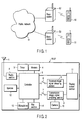
- FIGS. 1 - 3 show radio communication apparatuses with a videophone function according to a first embodiment.
- FIG. 1 shows a communication system including the radio communication apparatuses with the videophone functions according to the first embodiment.
- radio communication apparatuses 50 and 51 having the videophone function are connected to a public network 54 via base stations 52 and 53, respectively.
- the base stations 52 and 53 respectively provide the radio communication apparatuses 50 and 51 with respective service areas dedicated to the base stations 52 and 53.
- the base station that is located closest to each radio communication apparatus 50 or 51 and hence can receive the radio waves of each radio communication apparatus in a best condition is designated as the base station 52 or 53.
- the public network 54 is connected to a plurality of base stations located in various areas, and can communicate with a radio communication apparatus located even at a long distance via an appropriate base station.
- FIG. 2 is a block diagram illustrating the internal structure of each radio communication apparatus 50 or 51 with the videophone function according to the invention.
- each of the radio communication apparatuses 50 and 51 has a radio section 2 for transmitting and receiving radio waves to and from a corresponding one of the base stations 52 and 53.
- the radio section 2 is connected to an antenna 1 and receives radio waves through the antenna 1.
- the antenna 1 converts a received radio wave into a received signal.
- the radio section 2 subjects the received signal to high frequency amplification and frequency conversion, thereby amplifying low noise contained in the signal.
- a controller 5 generates a designation signal for designating a frequency and supplies the designation signal to the radio section 2.
- the radio section 2 converts the received signal, by frequency conversion, into an intermediate-frequency signal or a baseband signal, and demodulates the converted signal into a digital signal.
- the controller 5 executes control for establishing a communication channel based on a communication protocol. Upon establishing the communication channel, the controller 5 generates a call sound generating signal. A sounder (not shown) outputs the call sound generating signal, thereby informing the user of an incoming call. The user can also be notified about the incoming call by vibrating a vibrator (not shown) or turning on an LED (not shown), instead of generating the call sound.
- a call control section (not shown) receives the received signal from the radio section 2 over the communication channel.
- the call control section converts the demodulated signal into a speaker signal.
- a speaker section 12 receives the speaker signal and outputs a sound corresponding to the speaker signal.
- each radio communication apparatus 50 or 51 When the apparatus transmits radio waves containing voice information through the antenna 1, the operation of the key section 14 incorporated in each radio communication apparatus 50 or 51 generates an ON signal for turning on the apparatus called (50 or 51).
- the controller 5 receives the ON signal and turns on the corresponding apparatus (50 or 51). After that, a phone number assigned to another radio communication apparatus to communicate with is input by operating the key section 14, thereby generating a number signal corresponding to the phone number.
- the controller 5 receives the number signal and creates a radio control signal based on the number signal.
- the radio section 2 receives the radio control signal and encodes the phone number. Radio waves containing the encoded phone number are output through the antenna 1.
- the controller 5 controls the communication protocol to establish a communication channel.
- incoming call radio waves are transmitted to the radio communication apparatus with the phone number via the base station 52, the public network 54 and the base station 53.
- the radio communication apparatuses 50 and 51 are communicable.
- a voice input to a microphone 13 is converted into a voice signal and input to a call control section (not shown), where the input signal is digitally modulated.
- the communication channel is established as described above.
- the controller 5 detects a received signal. If the received signal contains the image data, the controller 5 establishes an interface for processing image data. Upon establishing the interface, the controller 5 outputs a digital signal containing the image data to a received-image-signal decoding section 8 via a decoding switch 6.
- the decoding switch 6 controls the output of an image signal from the controller 5 to the received-image-signal decoding section 8. Specifically, if the decoding switch 6 is in the ON state, the output of the image signal to the received-image-signal decoding section 8 is permitted, while if the decoding switch 6 is in the OFF state, the output of the image signal to the section 8 is interrupted.
- the decoding switch 6 has a function of interrupting the decoding of the image signal in the received-image-signal decoding section 8. That is, if the decoding switch 6 is in the ON state, the received signal is decoded by the received-image-signal decoding section 8, and if it is turned off, the decoding of the received signal by the section 8 is interrupted.
- the received-image-signal decoding section 8 decodes the image signal and then subjects the decoded image signal to D/A conversion, thereby converting the decoded image signal into an analog image signal.
- a display screen section 11 receives the analog image signal and displays an image based on the image data contained in the analog image signal.
- a camera 10 picks up an image and converts the image into an image signal.
- the image signal may be input to the apparatus via an image input terminal connected to an image input device such as a video recorder.
- a transmission image signal encoding section 9 encodes the image signal and converts the encoded image signal into a digital image signal containing the image data.
- the resultant signal is output to the controller 5 under the control of an encoding switch 7. If the encoding switch 7 is in the ON state, the encoding of the image signal by the transmission image signal encoding section 9 is continued, and the output of the image signal to the controller 5 is permitted.
- the encoding switch 7 controls the transmission image signal encoding section 9, by on or off switching, so as to reduce the power consumption of the section 9.
- Each radio communication apparatus 50 or 51 includes a memory 4 for storing phone numbers, an incoming call history, image data and voice data, etc. Further, each radio communication apparatus 50 or 51 also includes a timer 3 for monitoring the time period for displaying a received image during the execution of the videophone function. An image signal received for a predetermined time period after the start of a call is decoded and the image corresponding to the decoded image signal is displayed on the display screen section 11. After the predetermined time period elapses, an image stored in the memory 4 is displayed on the display screen section 11. The image stored in the memory 4 can be selected, by the user's operation of the key section 14, from image data transmitted, during the call, from the radio communication apparatus called.
- any voluntarily selected images may be stored in the memory 4 beforehand and displayed when necessary.
- An image previously stored in the memory 4 may be displayed.
- an image received from an image forming apparatus, such as a video recorder, a digital camera or a personal computer, connected to the input terminal (not shown) of the radio communication apparatus may be displayed.
- the radio communication apparatus may be programmed such that if the key section 14 is operated during the call to request the display of an image signal that is now being received, the received image signal is decoded and displayed, while if the key section 14 is not operated, an image stored in the radio communication apparatus is displayed.
- the image to be displayed can be voluntarily selected by the user's operation of the key section 14.
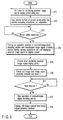
- the time period for displaying an image received during a videophone call is set in the timer 3 shown in FIG. 2, using the key section 14 shown in FIG. 2 (step ST1 in FIG. 3).
- the key section 14 is operated to input a phone number into the radio communication apparatus 50 or 51.
- a videophone call origination is generated (step ST2 in FIG. 3).
- the radio communication apparatus 50 or 51 waits for a response from the radio communication apparatus called (step ST3 in FIG. 3).
- the switches 6 and 7 shown in FIG. 2 are turned on, thereby operating the received-image-signal decoding section 8 and the transmission image signal encoding section 9.
- videophone communication for transmitting and receiving image and voice signals starts (step ST4 in FIG. 3).
- the timer 3 shown in FIG. 2 is operated to monitor the predetermined time period for displaying the image signal received during the execution of the videophone function (step ST5 in FIG. 3).
- a still image is extracted from the received image signal and stored in the memory 4 shown in FIG. 2, under the control of the controller 5 (step ST6 in FIG. 3). Subsequently, it is determined whether or not the predetermined time period for displaying a received image during the videophone call has elapsed (step ST7 in FIG. 3). The predetermined time was set while the radio communication apparatus was in the standby state. After the predetermined time period elapses, the switch 6 shown in FIG. 2 is turned off to thereby stop the operation of the received-image-signal decoding section 8 (step ST8 in FIG. 3). At this time, a still image extracted from the received image stored in the memory 4 shown in FIG. 2 is displayed on the display screen section 11 (step ST9 in FIG. 3).
- the current consumption of the received-image-signal decoding section 8 is reduced, thereby minimizing a reduction in the capacity of the battery due to the decoding of the received image signal. Furthermore, since a still image is displayed while image decoding is being stopped, the user does not have to worry about whether or not the decoding function is a breakdown when the image decoding is stopped. It is sufficient if the to-be-displayed image is any one of the images stored in the radio communication apparatus, and is not necessarily an image extracted from a received image signal. For example, a prestored picture of a person to communicate with may be displayed, using an address book function.
- the to-be-displayed image can be voluntarily selected and is not limited to the above.
- FIG. 4 is a flowchart useful in explaining in detail the step ST6 shown in FIG. 3.
- a description of a method, employed in the step ST6 of FIG. 3, for creating a still image from a received image signal will be given.
- a desired image will not be obtained.
- a still image may be extracted when the face of a person called is offscreen. In this case, the face of a person is not included in the still image.
- a received image signal is decoded (step ST1 in FIG. 4), and a standby state for waiting for a key input operation to request the creation of a still image is maintained (step ST2 in FIG. 4).
- a standby state for waiting for a key input operation to request the creation of a still image is maintained.
- a still image is created. Accordingly, it become rare that when the face of a person called is offscreen, a still image on the screen is extracted (step ST3 in FIG. 4).
- timer 3 for monitoring the time period for displaying a receiving image signal during a videophone call may be set to stop its time measuring when the key for requesting a still image has been pushed, so as to stop the decoding of the receiving image signal when a still image has been created as a result of the key input operation.
- the above embodiment can be modified so that transmission of image data to a radio communication apparatus as a destination is stopped, in addition to the stoppage of the decoding of the received image signal, after the predetermined time period for displaying a received image signal during a videophone call elapses.
- the transmission of an image signal can be also stopped by turning off, at the step ST9 in FIG. 3, the encoding switch 7 for controlling the operation of the transmission image signal encoding section 9 shown in FIG. 2.
- the radio communication apparatus as the destination can further reduce its current consumption, although the apparatus shows no images on the screen.
- the radio communication apparatus as the destination employs a memory as described above, it can display a still image stored in the memory 4.
- FIG. 5 is a flowchart useful in explaining the operation of decoding and displaying a received image signal only while the key input operation of requesting display of a received image signal is being executed during a videophone call, and displaying an image stored in the apparatus if there is no key input operation.
- a phone number is input to generate a videophone call origination (step ST1 in FIG. 5). Then, the radio communication apparatus 50 or 51 waits for a response to the call from a radio communication apparatus as a destination (step ST2 in FIG. 5).
- the switch 7 shown in FIG. 2 is turned on, thereby operating the transmission image signal encoding section 9.
- an image is transmitted to the radio communication apparatus as the destination and videophone communication starts (step ST3 in FIG. 5).
- an image stored in the apparatus is displayed on the display screen section 11 shown in FIG. 2 (step ST4 in FIG. 5). In this state, the key input operation for requesting display of a receiving image is waited for (step ST5 in FIG. 5).
- the switch 6 shown in FIG. 2 is turned on, thereby operating the received-image-signal decoding section 8, thereby decoding a signal received and displaying an image of the decoded signal on the display screen section 11 (step ST6 in FIG. 5). After that, termination of the key input operation of requesting the display of a received image is waited for (step ST7 in FIG. 5). After the key input operation is terminated, the switch 6 is turned off to stop the received-image-signal decoding section 8, followed by the program returning to the step ST4 (step ST8 in FIG. 5).
- the above-described operations enable a received image to be displayed only when a request for displaying the received image has been issued, and enable the received-image-signal decoding section 8 to be stopped if there is no such request. Accordingly, when there is no such request, the received-image-signal decoding section 8 does not consume power, and hence less power is consumed from the battery of the radio communication apparatus 50 or 51. Furthermore, when no received image is displayed, an image stored in the apparatus is displayed. Accordingly, the user does not have to worry about whether or not the decoding function is a breakdown when the image decoding is stopped.
- This embodiment can be also modified such that an image can be displayed for a predetermined time period after a key input operation is executed. If the above-described two methods are combined, the current consumption of the radio communication apparatus can be further reduced.
- the present invention can be modified in various ways without deviation from the gist.
- the invention may be modified such that the manner of communication can be switched between videophone communication and usual phone communication using only sound by pushing one key repeatedly.
- a circuit for decoding a received image signal is operated when necessary during a videophone call, thereby decoding and displaying the received image signal.
- the circuit When the circuit is not operated, it does not consume power. Accordingly, the power consumption of the entire apparatus is less than that of an apparatus in which a received image signal is always decoded and displayed.
- this structure is employed in a radio communication apparatus to be operated by a battery, such as a mobile phone, the power consumption of the battery can be suppressed since a received image is displayed only for a necessary period during a videophone call. This means that the duration of a call and the duration of standby obtained by one battery charge can be lengthened.
Landscapes
- Engineering & Computer Science (AREA)
- Multimedia (AREA)
- Signal Processing (AREA)
- Two-Way Televisions, Distribution Of Moving Picture Or The Like (AREA)
- Mobile Radio Communication Systems (AREA)
- Telephonic Communication Services (AREA)
- Telephone Function (AREA)
Abstract
Description
Claims (17)
- A radio communication apparatus characterized by comprising:receiving section (2) configured to receive a radio signal containing a voice signal and an image signal and demodulate said voice signal and said image signal;converting section (8) configured to receive said demodulated image signal from said receiving section (2) and decode said demodulated image signal; andcontrol section (5, 6, 8) configured to stop decoding said demodulated image signal that is supplied from said receiving section (2) to said converting section (8) during communication.
- Said radio communication apparatus according to claim 1, characterized in that said control section (5, 6, 8) includes switch section (6) configured to turn on and off said converting section (8).
- Said radio communication apparatus according to claim 1, characterized in that said image signal contains information on a moving picture and a still image, said moving picture consisting of a predetermined number of still images displayed repetitively per unit of time.
- Said radio communication apparatus according to claim 3, characterized in that said moving picture is displayed at a speed higher than 1 frame per unit of time.
- Said radio communication apparatus according to claim 1, characterized by further comprising timer section (3) configured to measure a predetermined period of time for which said image signal is output to said converting section (8), if said image signal is a moving picture signal.
- Said radio communication apparatus according to claim 1, characterized by further comprising memory section (4) configured to store said image signal decoded by said converting section (8).
- Said radio communication apparatus according to claim 6, characterized in that said memory section (4) also prestores an image signal.
- Said radio communication apparatus according to claim 7, characterized in that said image signal prestored in said memory section (4) is converted into a decoded image signal by said converting section (8) on said basis of an instruction from a user, and an image based on said converted image signal is displayed.
- Said radio communication apparatus according to claim 6, characterized in that said control section (5, 6, 8) includes:still image extracting section (8) configured to extract a still image signal from said image signal if said image signal is a moving picture signal; andsupply section (5) configured to supply said still image signal to said memory section (4).
- Said radio communication apparatus according to claim 6, characterized in that said control section (5, 6, 8) includes output switch section (5) configured to switch an output mode between an output mode for outputting only said voice signal and an output mode for outputting both said voice signal and said image signal.
- Said radio communication apparatus according to claim 6, characterized in that said control section (5, 6, 8) includes image signal supply section (5) configured to switch said image signal, decoded by said converting section (8), into an image signal having a smaller amount of data.
- A radio communication apparatus characterized by comprising:receiving section (2) configured to receive a radio signal containing a voice signal and an image signal and demodulate said voice signal and said image signal;converting section (8) configured to receive said demodulated image signal from said receiving section (2) and decode said demodulated image signal;control section (5, 6, 8) configured to turn on and off said converting section (8) so as to stop decoding said demodulated image signal that is supplied from said receiving section (2) to said converting section (8) during communication;timer section (3) configured to measure a predetermined period of time for which said image signal is output to said converting section (8), if said image signal is a moving picture signal; andmemory section (4) configured to store said image signal decoded by said converting section (8) and prestore an image signal obtained beforehand.
- Said radio communication apparatus according to claim 12, characterized in that said control section (5, 6, 8) includes:still image extracting section (8) configured to extract a still image signal from said image signal if said image signal is a moving picture signal; andsupply section (5) configured to supply said still image signal to said memory section (4).
- Said radio communication apparatus according to claim 12, characterized in that said control section (5, 6, 8) includes image signal supply section (5) configured to switch said image signal, decoded by said conversion section (8), into an image signal having a smaller amount of data.
- A radio communication apparatus characterized by comprising:receiving section (2) configured to receive a radio signal containing a voice signal and an image signal and demodulate said voice signal and said image signal;converting section (8) configured to receive said demodulated image signal from said receiving section (2) and decode said demodulated image signal;control section (5, 6, 8) configured to turn on and off said conversion section (8) so as to stop decoding said demodulated image signal that is supplied from said receiving section (2) to said converting section (8) during communication; andmemory section (4) configured to store said image signal decoded by said converting section (8) and prestore an image signal obtained beforehand.
- Said radio communication apparatus according to claim 15, characterized in that said control section (5, 6, 8) includes:still image extracting section (8) configured to extract a still image signal from said image signal if said image signal is a moving picture signal; andsupply section (5) configured to supply said still image signal to said memory section (4).
- Said radio communication apparatus according to claim 15, characterized in that said control section (5, 6, 8) includes image signal supply section (5) configured to switch said image signal, decoded by said converting section (8), into an image signal having a smaller amount of data.
Applications Claiming Priority (2)
| Application Number | Priority Date | Filing Date | Title |
|---|---|---|---|
| JP2000204101 | 2000-07-05 | ||
| JP2000204101A JP2002027145A (en) | 2000-07-05 | 2000-07-05 | Wireless communication terminal |
Publications (2)
| Publication Number | Publication Date |
|---|---|
| EP1170948A2 true EP1170948A2 (en) | 2002-01-09 |
| EP1170948A3 EP1170948A3 (en) | 2002-09-25 |
Family
ID=18701419
Family Applications (1)
| Application Number | Title | Priority Date | Filing Date |
|---|---|---|---|
| EP01115675A Withdrawn EP1170948A3 (en) | 2000-07-05 | 2001-07-04 | Radio communication apparatus |
Country Status (3)
| Country | Link |
|---|---|
| US (1) | US20020004415A1 (en) |
| EP (1) | EP1170948A3 (en) |
| JP (1) | JP2002027145A (en) |
Cited By (5)
| Publication number | Priority date | Publication date | Assignee | Title |
|---|---|---|---|---|
| EP1420588A3 (en) * | 2002-11-18 | 2004-09-08 | Nec Corporation | Communication terminal with tv telephone function |
| US7978764B2 (en) | 2003-06-27 | 2011-07-12 | Nxp B.V. | Method of video encoding for handheld apparatuses selecting best prediction function according to optimal rate-distortion value |
| WO2011131767A1 (en) | 2010-04-23 | 2011-10-27 | Skype Limited | Mobile device for selectively suppressing a video function of a packet-based video call |
| EP2317747A4 (en) * | 2008-10-10 | 2012-12-05 | Zte Corp | A realizing method and apparatus for video phone |
| US20130002798A1 (en) * | 2010-03-18 | 2013-01-03 | Nec Corporation | Mobile telephone set having video-phone function low in amount of heat generation |
Families Citing this family (9)
| Publication number | Priority date | Publication date | Assignee | Title |
|---|---|---|---|---|
| JP3927367B2 (en) * | 2001-01-16 | 2007-06-06 | 株式会社メガチップス | Integrated circuit for image processing |
| KR100754647B1 (en) | 2002-09-17 | 2007-09-05 | 삼성전자주식회사 | Television video signal display device and method of mobile terminal |
| KR100678204B1 (en) | 2002-09-17 | 2007-02-01 | 삼성전자주식회사 | Image and data display device and method according to mode of mobile terminal |
| JP2004179923A (en) * | 2002-11-27 | 2004-06-24 | Nec Corp | Mobile phone and self-made animation setting method for continuous shot image used therefor |
| US7277076B2 (en) * | 2002-12-27 | 2007-10-02 | Sharp Kabushiki Kaisha | Method of driving a display, display, and computer program therefor |
| JP2005184632A (en) * | 2003-12-22 | 2005-07-07 | Nec Access Technica Ltd | Power consumption reduction method in communication terminal, and communication terminal |
| US7805024B2 (en) * | 2004-05-05 | 2010-09-28 | Nokia Corporation | Method and apparatus to provide efficient multimedia content storage |
| JP2007013438A (en) * | 2005-06-29 | 2007-01-18 | Toshiba Corp | Audio image reproduction apparatus and operation control method |
| KR20170095885A (en) | 2014-12-22 | 2017-08-23 | 에씰로아 인터내셔날(콩파니에 제네랄 도프티크) | A method for adapting the sensorial output mode of a sensorial output device to a user |
Family Cites Families (8)
| Publication number | Priority date | Publication date | Assignee | Title |
|---|---|---|---|---|
| JPH05227263A (en) * | 1992-02-10 | 1993-09-03 | Fujitsu Ltd | Display system for cordless telephone set |
| US5949484A (en) * | 1995-03-08 | 1999-09-07 | Hitachi, Ltd. | Portable terminal apparatus for multimedia communication |
| JP3703185B2 (en) * | 1995-12-28 | 2005-10-05 | キヤノン株式会社 | Portable terminal device and control method thereof |
| US6028631A (en) * | 1997-09-08 | 2000-02-22 | Hitachi, Ltd. | Portable terminal apparatus for multimedia communication |
| JP3719482B2 (en) * | 1998-07-29 | 2005-11-24 | 株式会社デンソー | Wireless communication device |
| JP2000253140A (en) * | 1999-03-01 | 2000-09-14 | Sony Corp | Electronics |
| US6385469B1 (en) * | 1999-06-22 | 2002-05-07 | Ericsson Inc. | System and method for providing battery gapping for mobile stations |
| JP2001103437A (en) * | 1999-09-29 | 2001-04-13 | Toshiba Corp | Wireless video communication terminal |
-
2000
- 2000-07-05 JP JP2000204101A patent/JP2002027145A/en active Pending
-
2001
- 2001-07-04 EP EP01115675A patent/EP1170948A3/en not_active Withdrawn
- 2001-07-05 US US09/897,952 patent/US20020004415A1/en not_active Abandoned
Cited By (10)
| Publication number | Priority date | Publication date | Assignee | Title |
|---|---|---|---|---|
| EP1420588A3 (en) * | 2002-11-18 | 2004-09-08 | Nec Corporation | Communication terminal with tv telephone function |
| CN100399783C (en) * | 2002-11-18 | 2008-07-02 | 日本电气株式会社 | Communication terminal with TV telephone function |
| US7978764B2 (en) | 2003-06-27 | 2011-07-12 | Nxp B.V. | Method of video encoding for handheld apparatuses selecting best prediction function according to optimal rate-distortion value |
| EP2317747A4 (en) * | 2008-10-10 | 2012-12-05 | Zte Corp | A realizing method and apparatus for video phone |
| US20130002798A1 (en) * | 2010-03-18 | 2013-01-03 | Nec Corporation | Mobile telephone set having video-phone function low in amount of heat generation |
| US9277175B2 (en) | 2010-03-18 | 2016-03-01 | Lenovo Innovations Limited (Hong Kong) | Mobile telephone set having video-phone function low in amount of heat generation |
| WO2011131767A1 (en) | 2010-04-23 | 2011-10-27 | Skype Limited | Mobile device for selectively suppressing a video function of a packet-based video call |
| CN102860094A (en) * | 2010-04-23 | 2013-01-02 | 斯凯普公司 | Mobile device for selectively suppressing video capabilities for packet-based video calls |
| US9137348B2 (en) | 2010-04-23 | 2015-09-15 | Skype | Viewing apparatus |
| CN102860094B (en) * | 2010-04-23 | 2016-08-17 | 斯凯普公司 | Mobile device for selectively suppressing video capabilities for packet-based video calls |
Also Published As
| Publication number | Publication date |
|---|---|
| EP1170948A3 (en) | 2002-09-25 |
| JP2002027145A (en) | 2002-01-25 |
| US20020004415A1 (en) | 2002-01-10 |
Similar Documents
| Publication | Publication Date | Title |
|---|---|---|
| US7835688B2 (en) | Communication system | |
| US8036363B2 (en) | Communication terminal apparatus, communication method, and recording medium for establishing communications with a plurality of persons in a plurality of communication manners | |
| US6625478B1 (en) | Multifunction wireless telephone | |
| US20020004415A1 (en) | Radio communication apparatus | |
| JP2004221738A (en) | Videophone device and videophone control method | |
| EP1298894A2 (en) | Mobile radio terminal | |
| GB2385494A (en) | Setting quality of image data dependent on status of mobile terminal | |
| EP1298896A2 (en) | Electronic device and mobile radio terminal apparatus | |
| EP1048166B1 (en) | Image communication device and method for communication terminal | |
| US20050264650A1 (en) | Apparatus and method for synthesizing captured images in a mobile terminal with a camera | |
| EP1033876A1 (en) | Radio mobile terminal with a mountable and removable camera | |
| JP2002027045A (en) | Electronic equipment and its external connection equipment | |
| JP2002186029A (en) | Mobile radio terminal | |
| JP2000032421A (en) | Mobile videophone terminal | |
| JP3851020B2 (en) | Data communication system | |
| JP2001094500A (en) | Mobile communication device | |
| JP2001326972A (en) | Videophone system for complex mobile devices | |
| US20050113152A1 (en) | Method and apparatus for controlling power-off operation of mobile terminal | |
| JPH09331395A (en) | Image transmission equipment | |
| JP2002125208A (en) | Image telephone system | |
| KR100548617B1 (en) | Reservation shooting method on mobile communication terminal | |
| JP2002171567A (en) | Communication terminal device | |
| JP2004349899A (en) | Portable telephone terminal, television telephone function setting method used therefor and program therefor | |
| JPH0951376A (en) | Telephone device with memory | |
| JPH01256889A (en) | Visual telephone system |
Legal Events
| Date | Code | Title | Description |
|---|---|---|---|
| PUAI | Public reference made under article 153(3) epc to a published international application that has entered the european phase |
Free format text: ORIGINAL CODE: 0009012 |
|
| 17P | Request for examination filed |
Effective date: 20010704 |
|
| AK | Designated contracting states |
Kind code of ref document: A2 Designated state(s): AT BE CH CY DE DK ES FI FR GB GR IE IT LI LU MC NL PT SE TR |
|
| AX | Request for extension of the european patent |
Free format text: AL;LT;LV;MK;RO;SI |
|
| PUAL | Search report despatched |
Free format text: ORIGINAL CODE: 0009013 |
|
| AK | Designated contracting states |
Kind code of ref document: A3 Designated state(s): AT BE CH CY DE DK ES FI FR GB GR IE IT LI LU MC NL PT SE TR |
|
| AX | Request for extension of the european patent |
Free format text: AL;LT;LV;MK;RO;SI |
|
| AKX | Designation fees paid |
Designated state(s): DE GB |
|
| STAA | Information on the status of an ep patent application or granted ep patent |
Free format text: STATUS: THE APPLICATION HAS BEEN WITHDRAWN |
|
| 18W | Application withdrawn |
Effective date: 20030605 |