EP1170877A1 - Annuleur d'écho - Google Patents
Annuleur d'écho Download PDFInfo
- Publication number
- EP1170877A1 EP1170877A1 EP01410083A EP01410083A EP1170877A1 EP 1170877 A1 EP1170877 A1 EP 1170877A1 EP 01410083 A EP01410083 A EP 01410083A EP 01410083 A EP01410083 A EP 01410083A EP 1170877 A1 EP1170877 A1 EP 1170877A1
- Authority
- EP
- European Patent Office
- Prior art keywords
- coefficients
- signal
- echo
- circuit
- initialization phase
- Prior art date
- Legal status (The legal status is an assumption and is not a legal conclusion. Google has not performed a legal analysis and makes no representation as to the accuracy of the status listed.)
- Granted
Links
Images

Classifications
-
- H—ELECTRICITY
- H04—ELECTRIC COMMUNICATION TECHNIQUE
- H04B—TRANSMISSION
- H04B3/00—Line transmission systems
- H04B3/02—Details
- H04B3/20—Reducing echo effects or singing; Opening or closing transmitting path; Conditioning for transmission in one direction or the other
- H04B3/23—Reducing echo effects or singing; Opening or closing transmitting path; Conditioning for transmission in one direction or the other using a replica of transmitted signal in the time domain, e.g. echo cancellers
- H04B3/238—Reducing echo effects or singing; Opening or closing transmitting path; Conditioning for transmission in one direction or the other using a replica of transmitted signal in the time domain, e.g. echo cancellers using initial training sequence
Definitions
- the present invention relates to circuits allowing simultaneous transmission and reception of signals (communications "full duplex") via a transmission line, and in particular circuits of this type comprising a canceller echo.
- full duplex simultaneous transmission and reception of signals
- the signals are transmitted and received on different frequency ranges and, in a second type, they are transmitted and received over the same frequency range.
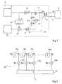
- FIG. 1 represents a conventional circuit 2 comprising such an echo canceller.
- Circuit 2 is planned to exchange signals with a central office 4 via a line of two-wire transmission 6.
- Circuit 2 includes a digital block transmission 8 and a digital reception block 10.
- Block 8 can receive the signals to be transmitted from a microprocessor (not shown) and block 10 can supply the signals received to the microprocessor, which processes them.
- Circuit 2 then acts modem.
- a digital to analog converter (DAC) 12 converts the digital signal supplied by the transmission block 8 in one analog output signal A.
- An analog-digital converter (ADC) 14 converts the corresponding analog signal R to the signal received as a digital signal supplied to the receiving block 10.
- DAC digital to analog converter
- ADC analog-digital converter
- An analog module 16 is disposed between the output of the converter 12, the input of converter 14 and a terminal 17 connected to one end of a primary winding of a transformer 18. The other end of the winding primary of transformer 18 is grounded, and the two ends of the secondary winding of transformer 18 are each connected to a wire of line 6.
- the module 16 includes a resistor R1 connected between the output of converter 12 and the terminal 17.
- the module 16 also includes a voltage divider formed of two resistors R2 and R3 connected in series between the converter output 12 and ground.
- An analog subtractor 19 is connected to subtract the signal from the voltage divider at the signal present on terminal 17. The output of the subtractor 19 is connected to the input of the converter 14.
- resistance R1 is equal to the impedance of the line, seen from the transformer primary 18. Consequently, signal A being supplied by converter 12, a signal A / 2 is found on terminal 17.
- the values resistors R2 and R3 are equal and the voltage divider provides an A / 2 signal at its midpoint.
- a signal B is provided by exchange 4
- the signal R supplied to converter 14 is free from interference from of the signal emitted A.
- Circuit 10 receives a echo signal, called "near echo". This close echo is due to a fraction of signal A which is found in signal R without having crossed the transmission line.
- the circuit also receives a weaker "far echo” echo signal due to reflection of the signal sent at the end of the transmission line.
- the present invention does not deal with the far echo signal, and the The term “echo” subsequently designates the near echo only.
- circuit 2 When there is an ⁇ A echo, the signal R is equal to B + ⁇ A.
- circuit 2 includes a digital echo canceller coupled between the output of block 8, the output of converter 14 and input of block 10.
- the canceller echo includes a digital filter 20 for producing a signal representative of the echo and a digital subtractor 22 to subtract this signal representative of the echo from the signal digital output by the converter 14.
- FIG. 2 schematically represents a conventional filter 20.
- the filter 20 comprises a predetermined number N of delay elements 26 i , where i is between 1 and N, connected in series.
- the first element 261 receives as input the samples corresponding to the digital signal supplied by the block 8.
- the elements 26 i each introduce a delay equal to the sampling period T of the transmitted digital signal.
- elements 26 i For each new sample D 0 received at the input of element 26 1 , elements 26 i each supply a sample D i respectively delayed by i periods with respect to sample D 0 .
- the filter 20 also includes N multipliers 28 i . Each multiplier 28 i is designed to multiply one of the delayed samples D i by a coefficient K i .
- the filter 20 includes an adder 30 which performs the sum of the products K i .D i .
- the adder 30 supplies the output signal of the filter 20, denoted E, corresponding to an estimate of the echo.
- the coefficients K i are produced by a calculation means, not shown for reasons of clarity.
- K i (t) K i (t-1) + ⁇ .Err (t) .D i (T)
- K i (t) and K i (t-1) are respectively the value of the coefficient K i at the time t of the iteration and during the iteration previous
- ⁇ is a predetermined attenuation factor
- Err (t) and D i (t) are respectively the output signal from the subtractor 22 and the sample D i at the instant t of the iteration.
- the Err (t) signal can be positive or negative.
- the value of the coefficients K i evolves until the signal Err (t) is substantially zero.
- the values of the coefficients K i then hardly evolve any more and are stored in a memory (not shown).
- the exchange of signals begins and the exchange transmits a signal B; the converter 14 receives an analog signal R equal to B + ⁇ A which it supplies, digitized, to the subtractor 22.
- the filter 20 provides the signal E corresponding to ⁇ A and block 10 receives a digital signal without echo.
- a drawback of such a device is that the values of the coefficients K i are fixed throughout the communication and correspond to the operating conditions of the circuit 2 during the initialization phase.
- the operating conditions may change, and the estimated echo signal E may no longer be equal to the actual echo signal.
- the circuit temperature increases and the transformer impedance may change.
- Such a phenomenon commonly occurs when the initialization phase takes place just after the circuit is energized, and the temperature of the circuit 2 and of the transformer 18 increases after the initialization phase. The echo, poorly compensated, then disturbs the reception signal, and can make it unusable.
- One solution then consists in interrupting the communication in progress, and in initiating a new communication. This allows a new calculation of the coefficients K i during a new initialization phase.
- this "brutal" solution is sometimes extremely troublesome. In the case of Internet communication, for example, such an interruption can lead to a loss of the connection.
- An object of the present invention is to provide a circuit with an echo canceller that works despite variations in operating conditions between phases initialization and nominal operation.
- Another object of the present invention is to provide such a circuit which is easy to realize from a structure of classic circuit.
- this invention provides a circuit for transmitting and receiving communications.
- the circuit includes a transmission block, a block reception, and an echo canceller, coupled to the transmission unit and at the receiving block, to determine an echo signal and the subtract from the received signal, determining the echo signal involving a predetermined number N of coefficients calculated at the start of each call during a phase initializing.
- the circuit includes means for bringing day periodically during communication a small group of coefficients chosen from the most significant coefficients.
- said restricted group is formed by the maximum coefficient obtained at the end of the initialization phase and a defined number of its neighbors.
- said restricted group is formed by all the coefficients of which the value at the end of the initialization phase is greater than a predetermined threshold.
- determining the coefficients during the initialization phase and updating the coefficients of said restricted group are performed iteratively, the calculation method for the updating of the coefficients of said group making the coefficients slower than the calculation method for determining coefficients during the initialization phase.
- echo canceller includes filter receiving samples emitted by the transmit block and providing the echo signal to a first entry of a subtractor from which a second entry receives samples received by the circuit and whose output is connected to the input of the receiving block.
- a restricted group of significant coefficients is identified among the coefficients K i , at the end of the initialization phase. Then, during the operation of the circuit, this restricted group of coefficients is periodically updated only.
- the applicant has developed this solution after various studies which have shown it, among other things, the impossibility of periodically updating all the coefficients of the filter 20.
- FIG. 3 represents a curve C illustrating the value of the coefficients of the filter 20 obtained at the end of an initialization phase.
- N 32 coefficients, but in practice, the number N can be arbitrary.
- the coefficient retained as being the most significant is the coefficient corresponding to the peak of the initialization curve.
- the maximum coefficient is the thirteenth coefficient, K 13 .
- the other significant coefficients can be determined in several ways.
- the other coefficients selected are the coefficients of rank immediately close to that of the maximum coefficient.
- the number of coefficients selected is a predetermined number. This number can be fixed, for example as a function of the total number of coefficients, or can be determined automatically from curve C by appropriate calculation means. In FIG. 3, for example, a group of five significant coefficients K j is chosen, comprising the rank coefficients 11, 12, 13, 14 and 15.
- K j (t) K j (t-1) + ⁇ '.Err (t) .D j (T)
- j is the rank of any of the coefficients selected (11, 12, 13, 14 or 15 in the example given)
- K j (t) and K j (t-1) are respectively the value of the coefficient Kj at the instant t of the iteration and during the previous iteration, where ⁇ 'is a predetermined attenuation factor
- Err (t) and D j (t) are respectively the output signal of the subtractor 22 and sample D j at time t of the iteration.
- the calculation means intended to implement the formula (2) can be the same as the calculation means for use formula (1), ordered to process only the restricted group of coefficients Kj.
- the attenuation coefficient ⁇ ' is chosen smaller than the attenuation coefficient ⁇ of the initialization phase.
- a difficulty in updating the coefficients during communication is that the signal received R includes both the signal from central exchange B and the echo ⁇ A, much lower than B. If we take a coefficient ⁇ 'of the order of ⁇ , the successive iterations do not converge and the coefficients take outliers. However, as the signal B is generally very uncorrelated with respect to the echo, is possible, with a coefficient ⁇ 'lower than ⁇ , to reduce the speed of evolution of the coefficients Kj and of obtaining their convergence. For example, ⁇ 'could be chosen 8 times lower to ⁇ .
- the choice of a limited number of coefficients to update, associated with a lower value of ⁇ tracks changes in operating conditions of the circuit.
- the estimated echo remains continuously close to the real echo and the signal to noise ratio of the signal supplied to reception block 10 remains acceptable.
- the update can be performed continuously during the communication.
- the coefficients of the selected restricted group will be updated one after the others, starting for example with the value coefficient la higher.
- updating the restricted group can be performed periodically, a time interval separating two successive updates.
- the significant coefficients selected could be a number predetermined coefficients near the maximum coefficient.
- the coefficients retained are the coefficients whose value, at the end of the initialization phase, is greater than or equal to a percentage predetermined value of the maximum coefficient. In this variant, this percentage can be set according to the number total of coefficients, or can be determined automatically at from curve C by appropriate calculation means.
- each coefficient Kj is calculated from the product of the value of the sample D j (t) supplied by the delay element 26 j and of the output of the subtractor 22 Err (t), but a person skilled in the art will easily adapt the present invention to a filter in which each coefficient is initialized from an average of the sample products Dj to D j + k-1 and the outputs of the subtractor 22 Err (t) to Err (t-k + 1), where the update is made every k samples, according to the formula: 1 being a variable going from 0 to k-1.
Landscapes
- Engineering & Computer Science (AREA)
- Computer Networks & Wireless Communication (AREA)
- Signal Processing (AREA)
- Cable Transmission Systems, Equalization Of Radio And Reduction Of Echo (AREA)
Abstract
Description
Claims (5)
- Circuit pour émettre et recevoir des communications, comprenant :caractérisé en ce que ledit groupe restreint est formé par le coefficient maximal obtenu à l'issue de la phase d'initialisation et un nombre défini de ses voisins.un bloc d'émission (8),un bloc de réception (10),un annuleur d'écho (20, 22), couplé au bloc d'émission et au bloc de réception, pour déterminer un signal d'écho et le soustraire du signal reçu, la détermination du signal d'écho faisant intervenir un nombre prédéterminé N de coefficients (Ki) calculés au début de chacune des communications lors d'une phase d'initialisation, etdes moyens pour mettre à jour périodiquement en cours de communication un groupe restreint de coefficients choisis parmi les coefficients les plus significatifs,
- Circuit selon la revendication 1, dans lequel la détermination des coefficients lors de la phase d'initialisation et la mise à jour des coefficients dudit groupe restreint sont effectuées de façon itérative, le mode de calcul pour la mise à jour des coefficients (Kj) dudit groupe faisant converger les coefficients plus lentement que le mode de calcul pour la détermination des coefficients (Ki) lors de la phase d'initialisation.
- Circuit selon la revendication 1 ou 2, dans lequel l'annuleur d'écho comprend un filtre (20) recevant des échantillons émis par le bloc d'émission et fournissant le signal d'écho à une première entrée d'un soustracteur (22) dont une seconde entrée reçoit des échantillons reçus par le circuit et dont la sortie est connectée à l'entrée du bloc de réception.
- Circuit selon la revendication 3, dans lequel le filtre (20) comprend :N éléments de retard (26i) connectés en série, recevant les échantillons émis,N multiplieurs, chaque multiplieur (28i) étant prévu pour multiplier par un des coefficients (Ki) l'échantillon en sortie de l'élément de retard de même rang (26i), etun additionneur (30) pour faire la somme des signaux en sortie des multiplieurs.
- Procédé d'annulation d'écho dans un circuit propre à émettre et/ou recevoir un signal respectivement émis et/ou reçu, dans lequel un signal représentatif de l'écho est soustrait au signal reçu, le signal représentatif de l'écho étant déterminé en faisant la somme de N termes, chaque terme étant obtenu en multipliant un échantillon de rang i (Di) du signal émis par un coefficient de rang i (Ki), i étant compris entre 1 et N,
comprenant les étapes suivantes :lors d'une phase d'initialisation correspondant au début d'une communication, déterminer la valeur des N coefficients de rang i (Ki),déterminer les coefficients les plus significatifs, etau cours de la communication, mettre à jour les coefficients (Kj) d'un groupe restreint desdits coefficients choisis parmi les coefficients les plus significatifs, ledit groupe restreint étant formé par le coefficient maximal obtenu à l'issue de la phase d'initialisation et un nombre défini de ses voisins.
Applications Claiming Priority (2)
| Application Number | Priority Date | Filing Date | Title |
|---|---|---|---|
| FR0008745A FR2811492A1 (fr) | 2000-07-05 | 2000-07-05 | Cirtcuit d'emission et de reception comportant un annuleur d'echo |
| FR0008745 | 2000-07-05 |
Publications (2)
| Publication Number | Publication Date |
|---|---|
| EP1170877A1 true EP1170877A1 (fr) | 2002-01-09 |
| EP1170877B1 EP1170877B1 (fr) | 2008-10-29 |
Family
ID=8852135
Family Applications (1)
| Application Number | Title | Priority Date | Filing Date |
|---|---|---|---|
| EP01410083A Expired - Lifetime EP1170877B1 (fr) | 2000-07-05 | 2001-07-05 | Annuleur d'écho |
Country Status (4)
| Country | Link |
|---|---|
| US (1) | US7065056B2 (fr) |
| EP (1) | EP1170877B1 (fr) |
| DE (1) | DE60136314D1 (fr) |
| FR (1) | FR2811492A1 (fr) |
Families Citing this family (6)
| Publication number | Priority date | Publication date | Assignee | Title |
|---|---|---|---|---|
| US7796544B2 (en) * | 2002-06-07 | 2010-09-14 | Tokyo Electron Limited | Method and system for providing an analog front end for multiline transmission in communication systems |
| KR100502414B1 (ko) * | 2002-11-22 | 2005-07-19 | 삼성전자주식회사 | 에이디에스엘 시스템의 에코 제거기 및 그것의 트레이닝방법 |
| US7013226B2 (en) * | 2003-10-14 | 2006-03-14 | Intel Corporation | Reflectometer with echo canceller |
| US20060088123A1 (en) * | 2004-10-21 | 2006-04-27 | Jensen Henrik T | Method and system for Gaussian filter modification for improved modulation characteristics in Bluetooth RF transmitters |
| TWI339513B (en) * | 2006-12-21 | 2011-03-21 | Realtek Semiconductor Corp | Passive echo cancellation device and signal transmission method thereof |
| US20120147790A1 (en) * | 2010-12-13 | 2012-06-14 | Nec Laboratories America, Inc. | Method for a Canceling Self Interference Signal Using Active Noise Cancellation in RF Circuits and Transmission Lines for Full Duplex Simultaneous (In Time) and Overlapping (In Space) Wireless Transmission & Reception on the Same Frequency band |
Citations (3)
| Publication number | Priority date | Publication date | Assignee | Title |
|---|---|---|---|---|
| US5418778A (en) * | 1992-02-14 | 1995-05-23 | Itt Corporation | Local and remote echo canceling apparatus particularly adapted for use in a full duplex modem |
| EP0798877A2 (fr) * | 1996-03-25 | 1997-10-01 | Motorola, Inc. | Annuleur d'echo divisé utilisant une localisation d'écho par décimation |
| US5920548A (en) * | 1996-10-01 | 1999-07-06 | Telefonaktiebolaget L M Ericsson | Echo path delay estimation |
Family Cites Families (1)
| Publication number | Priority date | Publication date | Assignee | Title |
|---|---|---|---|---|
| IT1208769B (it) * | 1983-10-12 | 1989-07-10 | Cselt Centro Studi Lab Telecom | Teristiche varianti nel tempo procedimento e dispositivo per la cancellazione numerica dell eco generato in collegamenti con carat |
-
2000
- 2000-07-05 FR FR0008745A patent/FR2811492A1/fr not_active Withdrawn
-
2001
- 2001-06-29 US US09/896,827 patent/US7065056B2/en not_active Expired - Lifetime
- 2001-07-05 EP EP01410083A patent/EP1170877B1/fr not_active Expired - Lifetime
- 2001-07-05 DE DE60136314T patent/DE60136314D1/de not_active Expired - Lifetime
Patent Citations (3)
| Publication number | Priority date | Publication date | Assignee | Title |
|---|---|---|---|---|
| US5418778A (en) * | 1992-02-14 | 1995-05-23 | Itt Corporation | Local and remote echo canceling apparatus particularly adapted for use in a full duplex modem |
| EP0798877A2 (fr) * | 1996-03-25 | 1997-10-01 | Motorola, Inc. | Annuleur d'echo divisé utilisant une localisation d'écho par décimation |
| US5920548A (en) * | 1996-10-01 | 1999-07-06 | Telefonaktiebolaget L M Ericsson | Echo path delay estimation |
Also Published As
| Publication number | Publication date |
|---|---|
| DE60136314D1 (de) | 2008-12-11 |
| US7065056B2 (en) | 2006-06-20 |
| EP1170877B1 (fr) | 2008-10-29 |
| FR2811492A1 (fr) | 2002-01-11 |
| US20020048265A1 (en) | 2002-04-25 |
Similar Documents
| Publication | Publication Date | Title |
|---|---|---|
| EP0096936B1 (fr) | Procédé destiné à réduire le temps de convergence d'un annuleur d'écho et dispositif utilisé pour mettre en oeuvre ce procédé | |
| EP1420555B1 (fr) | Procédé et système pour l'estimation d'un canal de transmission au moyen des séquences complémentaires | |
| EP1811673B1 (fr) | Dispositif de conversion analogique numérique à entrelacement temporel et à égalisation auto adaptative | |
| EP0113487B1 (fr) | Procédé utilisé dans un dispositif d'annulation d'écho pour la mesure d'un retard d'écho et dispositif de mise en oeuvre de ce procédé | |
| EP0116387B1 (fr) | Procédé d'initialisation des coefficients de filtres dans un dispositif d'annulation d'échos proche et lointain et dispositif de mise en oeuvre de ce procédé | |
| EP0164159B1 (fr) | Dispositif de commande d'un annuleur d'écho et d'un écrêteur de centre | |
| EP0146979B1 (fr) | Procédé et dispositif pour la détermination de la position optimale du coefficient de référence d'un égaliseur adaptatif | |
| FR2501436A1 (fr) | ||
| EP0117596B1 (fr) | Procédé de réduction du temps de convergence d'un annuleur d'écho et dispositif pour mettre en oeuvre ce procédé | |
| EP1170877B1 (fr) | Annuleur d'écho | |
| FR2517906A1 (fr) | Annulateur d'echo a commande automatique de gain pour systemes de transmission | |
| FR2731123A1 (fr) | Correction de gain de haut-parleur pour un terminal telephonique mains-libres | |
| EP0146175A1 (fr) | Dispositif de localisation d'un point de réflexion de signal sur une ligne de transmission | |
| FR2480534A1 (fr) | Procede et dispositif d'annulation d'echo dans un systeme de transmission de donnees | |
| EP0044598A1 (fr) | Dispositif d'annulation d'un signal d'écho composite | |
| CH629632A5 (fr) | Dispositif de controle automatique du gain d'une voie de reception d'une installation de transmission comportant des liaisons optiques. | |
| FR2490901A1 (fr) | Annuleur d'echo numerique muni d'un convertisseur analogique-numerique a dynamique reglable | |
| EP0275790B1 (fr) | Terminal de transmission de données sur une voie analogique bidirectionnelle avec annulation d'écho couplée au rythme réception | |
| EP2074705A1 (fr) | Procede d'estimation de canal dans un systeme coordonne lors de la mise en service d'une ligne | |
| FR2546693A1 (fr) | Annuleur d'echo a filtre numerique adaptatif pour systeme de transmission | |
| FR2515454A1 (fr) | Dispositif de reduction de brouillage | |
| EP1077530B1 (fr) | Procédé et dispositif de conversion d'un signal analogique en un signal numérique avec contrôle automatique de gain | |
| EP1213884A1 (fr) | Procédé et dispositif d'estimation des valeurs successives de symboles numériques, en particulier pour l'égalisation d'un canal de transmission d'informations en téléphonie mobile | |
| EP0070236B1 (fr) | Dispositif de compensation de phase d'écho et son application aux annuleurs d'écho | |
| EP0643516A1 (fr) | Dispositif de détection de rupture de ligne |
Legal Events
| Date | Code | Title | Description |
|---|---|---|---|
| PUAI | Public reference made under article 153(3) epc to a published international application that has entered the european phase |
Free format text: ORIGINAL CODE: 0009012 |
|
| AK | Designated contracting states |
Kind code of ref document: A1 Designated state(s): AT BE CH CY DE DK ES FI FR GB GR IE IT LI LU MC NL PT SE TR Kind code of ref document: A1 Designated state(s): DE FR GB IT |
|
| AX | Request for extension of the european patent |
Free format text: AL;LT;LV;MK;RO;SI |
|
| 17P | Request for examination filed |
Effective date: 20020619 |
|
| AKX | Designation fees paid |
Free format text: DE FR GB IT |
|
| 17Q | First examination report despatched |
Effective date: 20061120 |
|
| GRAP | Despatch of communication of intention to grant a patent |
Free format text: ORIGINAL CODE: EPIDOSNIGR1 |
|
| GRAS | Grant fee paid |
Free format text: ORIGINAL CODE: EPIDOSNIGR3 |
|
| GRAA | (expected) grant |
Free format text: ORIGINAL CODE: 0009210 |
|
| AK | Designated contracting states |
Kind code of ref document: B1 Designated state(s): DE FR GB IT |
|
| REG | Reference to a national code |
Ref country code: GB Ref legal event code: FG4D Free format text: NOT ENGLISH |
|
| REF | Corresponds to: |
Ref document number: 60136314 Country of ref document: DE Date of ref document: 20081211 Kind code of ref document: P |
|
| PG25 | Lapsed in a contracting state [announced via postgrant information from national office to epo] |
Ref country code: IT Free format text: LAPSE BECAUSE OF FAILURE TO SUBMIT A TRANSLATION OF THE DESCRIPTION OR TO PAY THE FEE WITHIN THE PRESCRIBED TIME-LIMIT Effective date: 20081029 |
|
| PLBE | No opposition filed within time limit |
Free format text: ORIGINAL CODE: 0009261 |
|
| STAA | Information on the status of an ep patent application or granted ep patent |
Free format text: STATUS: NO OPPOSITION FILED WITHIN TIME LIMIT |
|
| 26N | No opposition filed |
Effective date: 20090730 |
|
| REG | Reference to a national code |
Ref country code: FR Ref legal event code: PLFP Year of fee payment: 16 |
|
| REG | Reference to a national code |
Ref country code: FR Ref legal event code: PLFP Year of fee payment: 17 |
|
| REG | Reference to a national code |
Ref country code: FR Ref legal event code: PLFP Year of fee payment: 18 |
|
| PGFP | Annual fee paid to national office [announced via postgrant information from national office to epo] |
Ref country code: FR Payment date: 20190621 Year of fee payment: 19 |
|
| PGFP | Annual fee paid to national office [announced via postgrant information from national office to epo] |
Ref country code: GB Payment date: 20190624 Year of fee payment: 19 |
|
| PGFP | Annual fee paid to national office [announced via postgrant information from national office to epo] |
Ref country code: DE Payment date: 20200622 Year of fee payment: 20 |
|
| GBPC | Gb: european patent ceased through non-payment of renewal fee |
Effective date: 20200705 |
|
| PG25 | Lapsed in a contracting state [announced via postgrant information from national office to epo] |
Ref country code: FR Free format text: LAPSE BECAUSE OF NON-PAYMENT OF DUE FEES Effective date: 20200731 Ref country code: GB Free format text: LAPSE BECAUSE OF NON-PAYMENT OF DUE FEES Effective date: 20200705 |
|
| REG | Reference to a national code |
Ref country code: DE Ref legal event code: R071 Ref document number: 60136314 Country of ref document: DE |