EP1170829A2 - Electrical connector with sealing system - Google Patents
Electrical connector with sealing system Download PDFInfo
- Publication number
- EP1170829A2 EP1170829A2 EP01115542A EP01115542A EP1170829A2 EP 1170829 A2 EP1170829 A2 EP 1170829A2 EP 01115542 A EP01115542 A EP 01115542A EP 01115542 A EP01115542 A EP 01115542A EP 1170829 A2 EP1170829 A2 EP 1170829A2
- Authority
- EP
- European Patent Office
- Prior art keywords
- diameter
- seal
- contact
- wire
- insulator
- Prior art date
- Legal status (The legal status is an assumption and is not a legal conclusion. Google has not performed a legal analysis and makes no representation as to the accuracy of the status listed.)
- Granted
Links
Images

Classifications
-
- H—ELECTRICITY
- H01—ELECTRIC ELEMENTS
- H01R—ELECTRICALLY-CONDUCTIVE CONNECTIONS; STRUCTURAL ASSOCIATIONS OF A PLURALITY OF MUTUALLY-INSULATED ELECTRICAL CONNECTING ELEMENTS; COUPLING DEVICES; CURRENT COLLECTORS
- H01R13/00—Details of coupling devices of the kinds covered by groups H01R12/70 or H01R24/00 - H01R33/00
- H01R13/46—Bases; Cases
- H01R13/52—Dustproof, splashproof, drip-proof, waterproof, or flameproof cases
- H01R13/5205—Sealing means between cable and housing, e.g. grommet
- H01R13/5208—Sealing means between cable and housing, e.g. grommet having at least two cable receiving openings
-
- H—ELECTRICITY
- H01—ELECTRIC ELEMENTS
- H01R—ELECTRICALLY-CONDUCTIVE CONNECTIONS; STRUCTURAL ASSOCIATIONS OF A PLURALITY OF MUTUALLY-INSULATED ELECTRICAL CONNECTING ELEMENTS; COUPLING DEVICES; CURRENT COLLECTORS
- H01R13/00—Details of coupling devices of the kinds covered by groups H01R12/70 or H01R24/00 - H01R33/00
- H01R13/44—Means for preventing access to live contacts
- H01R13/443—Dummy plugs
-
- H—ELECTRICITY
- H01—ELECTRIC ELEMENTS
- H01R—ELECTRICALLY-CONDUCTIVE CONNECTIONS; STRUCTURAL ASSOCIATIONS OF A PLURALITY OF MUTUALLY-INSULATED ELECTRICAL CONNECTING ELEMENTS; COUPLING DEVICES; CURRENT COLLECTORS
- H01R13/00—Details of coupling devices of the kinds covered by groups H01R12/70 or H01R24/00 - H01R33/00
- H01R13/46—Bases; Cases
- H01R13/52—Dustproof, splashproof, drip-proof, waterproof, or flameproof cases
- H01R13/5219—Sealing means between coupling parts, e.g. interfacial seal
- H01R13/5221—Sealing means between coupling parts, e.g. interfacial seal having cable sealing means
Definitions
- One type of connector includes a rigid insulator of rigid molded engineering plastic, which is a material having a Young's modulus of elasticity of at least 100,000 psi, and a seal member of elastomeric material, which is a material having a Young's modulus of elasticity of no more than 50,000 psi.
- the rigid insulator and elastomeric seal member have aligned passages which receive contacts that have wires extending rearwardly therefrom. The wires extend through and behind the seal member.
- the rigid insulator forms forwardly and rearwardly facing shoulders that engage corresponding shoulders on the contact to prevent movement of the contact, while the seal member seals to the wire to prevent water or other fluids from passing therethrough to the exposed parts of the contact and wire.
- contacts carry signals and have maximum diameters that are not much greater than the diameter of the wire extending therefrom.
- some contacts have a large diameter, such as contacts for carrying power and coaxial contacts that have center and outer contact parts. It is often possible to connect wires of moderately small diameter to such large diameter contacts.
- wires of moderately small diameter to such large diameter contacts.
- the contact can be pushed into place and removed through the seal passage without damage.
- a large difference in diameters results in damage to the seal passage as the large diameter contact is pushed through the seal passage.
- an improved connector of the type that has a rigid insulator and an elastomeric seal member behind the rigid insulator, with a contact being securely held in the rigid insulator and a wire that extends from the contact being sealed to the seal member.
- the improved connector enables a contact to pass through the seal passage without damage to the seal passage, despite a large difference in diameter between the maximum diameter of the contact and the outside diameter of the wire extending therefrom.
- the connector includes a modular elastomeric insert having a tubular inside surface lying in interference fit with the wire to seal to it and having an outside surface lying in an interference fit with the corresponding seal passage.
- the modular insert is threaded on the wire so the contact can pass through the insulator passage without the insert in place, the insert then being forced into the insulator passage.
- the connector can include additional contacts with wires extending therefrom, where there is not such a large difference in diameters between the largest diameter of the contact and the outside of the wire, so those smaller contacts can be forced through sealing walls of the sealing passage without damage to them and with the sealing walls being integral with the rest of the seal member.
- Figs. 1 and 2 illustrate a connector 10 which has large contacts 12 and small contacts 14.
- the particular large contact assemblies or contacts 12 are power contacts that carry large currents and therefore require a larger area and larger cross section to minimize heating, while the small contacts 14 are signal contacts that carry signals of low current.
- the contacts mate to contacts of another connector by moving in a forward direction F.
- Wires 20 have front ends terminated to the large contacts and extend rearwardly R from the connector, while smaller wires 22 are connected to the smaller contacts and extend rearwardly from the connector.
- the connector includes a connector body 30 with a rigid insulator 32 that fixes the positions of the contacts 12, 14 and an elastomeric seal member 34 that seals to the wires 20, 22 to keep moisture away from the location where the wires terminate to the contacts.
- the rigid insulator includes front and rear parts 40, 42 that are each molded of a rigid engineering polymer, which is a polymer having a Young's modulus of elasticity of at least 100,000 psi.
- the seal member 34 is molded of elastomeric material, which is material having a Young's modulus of elasticity of less than 50,000 psi.
- the front end of the seal member is fixed to the rigid insulator as by adhesive or thermal bonding.
- Each large contact assembly or contact 12 includes a sheet metal lock ring 60 on a solid machined part 61.
- the contact includes a contact front portion 50 for engaging a mating contact, a rearwardly-facing shoulder 52 and two forwardly-facing shoulders 54, 56.
- the sheet metal ring lock 60 is formed by a piece of sheet metal rolled into a cylinder with a gap indicated at 58.
- the lock ring has an inwardly angled front end forming a forwardly-facing shoulder 64 that abuts the contact shoulder 52, and has a lock ring rear shoulder 59 that abuts the contact shoulder 56. This keeps the lock ring in place on the rest (part 61) of the contact.
- the shoulder 59 on the ring lock snaps behind a forwardly-facing shoulder 65 on the insulator part 42 to prevent contact removal.
- the forwardly-facing shoulder 54 on the contact substantially abuts a rearwardly-facing shoulder 66 formed at a rear surface of the rigid insulator, to prevent any further forward movement of the large contact.
- the rigid insulator 32 has contact-holding passages 70 that receive the large contacts, while the elastomeric seal member 34 has corresponding seal passages 72 that receive the large contacts and through which the large wires 20 extend.
- the small contacts 14 are held in a manner similar to that for the large contacts, with the rigid insulator 32 having tines 80 with free front ends forming forwardly-facing shoulders that engage rearwardly-facing shoulders 82 on small contacts.
- the rigid insulator also forms a rearwardly-facing shoulder 84 that engages a forwardly-facing shoulder 86 of the small contact.
- the small contacts like the large ones, can be installed by sliding them forwardly into place, until resilient shoulders snap behind the rearwardly-facing shoulders of the contacts.
- the small wires 22 each includes a copper core 90 and an insulator 92 surrounding the core.
- the front end of the insulator is stripped, the front end 96 of the core is inserted into a sleeve 100 at the rear end of the small contact, and the wire core is terminated to the contact. Termination can be accomplished by crimping the sleeve 100.
- Another type of sleeve enables soldering of the core front end 96 to the contact sleeve.
- the rigid insulator forms small passages 102 that receive the small contacts, while the elastomeric seal member 34 forms small seal passages 104 through which the contact and small wires 22 extend.
- the seal member forms internal ridges 110 that project radially inwardly towards the axis 112 of the seal passage, to seal to the outside of the wire 22.
- the internal diameter of the internal ridges results in an interference fit with the wire 22 to provide a moisture-tight seal.
- the internal diameter is less than the maximum diameter B of the small contact.
- the contact can be gently pushed through the internal ridges 110 to the installed position of the contact, without permanent damage to the internal ridges that would result in the absence of a moisture seal against the small wire 22.
- the diameter of the small passage 104 in the elastomeric seal member is preferably about equal to the maximum diameter B of the contact, and in almost all cases the diameter of the passage 104 is at least 95% of the contact maximum diameter B to enable insertion of the contact.
- the large wire 20 includes an insulator 120 and a copper core 122.
- the core is terminated to a sleeve 124 of the large contact in the same way as for the small contact, as by crimping the sleeve around the front end 126 of the core.
- the large wire 20 is sealed in place by internal ridges 130 in the seal passage that lie in interference fit with the large wire. It would be possible to form the large ridges 130 integrally with the rest of the seal member 34, as is done for the small ridges 110 that seal against the small contacts and wires. However, there would be disadvantages in making the large internal ridges 130 integral with the seal member 34. This is because the largest diameter D4 of a part 132 of the large contact is much larger than the diameter D2 of the large wire.
- the large internal ridges 130 at the tubular inside surfaces 134 of elastomeric module inserts 140 that are molded separately from the seal member 34.
- a modular insert 140 is slipped onto a large wire 20 prior to termination of the wire core front end 126 to the contact. After termination of the wire to the contact, the contact is pushed forwardly through passages 72, 70 in the seal member and in the rigid insulator, until the large contact is in or very close to being in its fully installed position. Then, the modular insert 140 is pushed forwardly into the seal passage.
- the seal member has an internal flange 150 with a forwardly-facing flange surface 152.
- the modular insert 140 is slightly compressed as it is pushed past the flange, until a rearwardly-facing insert surface 154 at the rear of the insert abuts the flange surface 152. At that time, the insert is slightly compressed against a rear end 156 of the contact and the outer surface 158 of the insert lies in an interference fit with the inside of the seal body.
- the insert is preferably not bonded in place, to permit replacement of a contact.
- the inside diameter D5 of the seal passage 72 is preferably about the same as the maximum outside diameter D4 of the contact, although it is possible to use a seal passage 72 that is as little as 95% of the maximum contact diameter.
- Applicant finds that sealing of the small internal ridges 110 to the wire can be maintained after the contact is pushed through the ridges, with this ratio of 1.8 of the contact maximum diameter to the wire outside diameter.
- the large contact had a largest diameter D4 of 5,72 mm (225 mils), while the wire had a diameter D2 of 2,54 mm (100 mils), for a ratio of 225/100 or 2.25:1.
- each large seal member passage diameter D5 was 5,77 mm (0.227 inch) which was more than 250% the diameter D6 of each insert internal ridge.
- the inside diameter D6 is 1,78 mm (0.07 inch).
- Fig. 5 shows a connector 200 of another embodiment of the invention, where the large contacts 202 are each a coaxial contact with a pin-like center contact part 204 and a socket type outer coaxial contact part 206.
- the connector includes a body 210 with a rigid insulator 212 of a molded rigid engineering polymer in each of its parts 214, 216, and an elastomeric seal member 220.
- the rigid insulator 212 has passages 222 aligned with corresponding passages 224 in the seal member.
- a coaxial wire or cable 230 has an outer conductor 232 terminated to the outer contact part, and has a center conductor 234 terminated to the inner contact part 204.
- the outer contact part 206 is of sheet metal, in which slots have been formed to leave tines 240 with rearwardly-facing shoulders 242 that engage shoulders 244 on the rigid insulator.
- a forwardly-facing shoulder 250 on the contact engages a shoulder 252 on the rigid insulator.
- An elastomeric modular insert 252 seals the wire 230 to the inside of the seal member passage 224. It is noted that a contact with a socket part 206 is difficult to force through internal seal ridges, and the modular insert 252 is especially useful in this case.
- the invention provides a connector with a rigid insulator and an elastomeric seal member having aligned passages that hold a contact with a wire extending rearwardly from the contact and which seals to the wire, which avoids damage to the seal despite a large difference between the largest diameter of the contact and the diameter of the wire. Where such a large difference exists, damage to the seal is avoided by providing a separate elastic modular insert that is inserted into the seal passage after the contact has been installed.
- the seal insert can lie in a passage of a connector seal member, which has one or more small passages where the largest diameter of the contact is not that much greater than the outside diameter of the corresponding small wire, and where the seal ridges that press against the outside of the wire are integrally formed with the rest of the seal member instead of being formed as separate inserts.
- the seal member preferably has an internal flange at the rear of each passage that is to hold a modular insert, and the modular insert is pushed past the flange and thereafter held in place by the flange.
Abstract
Description
- One type of connector includes a rigid insulator of rigid molded engineering plastic, which is a material having a Young's modulus of elasticity of at least 100,000 psi, and a seal member of elastomeric material, which is a material having a Young's modulus of elasticity of no more than 50,000 psi. The rigid insulator and elastomeric seal member have aligned passages which receive contacts that have wires extending rearwardly therefrom. The wires extend through and behind the seal member. The rigid insulator forms forwardly and rearwardly facing shoulders that engage corresponding shoulders on the contact to prevent movement of the contact, while the seal member seals to the wire to prevent water or other fluids from passing therethrough to the exposed parts of the contact and wire.
- Most contacts carry signals and have maximum diameters that are not much greater than the diameter of the wire extending therefrom. However, some contacts have a large diameter, such as contacts for carrying power and coaxial contacts that have center and outer contact parts. It is often possible to connect wires of moderately small diameter to such large diameter contacts. However, there is a problem in assuring a seal between the walls of the seal passage and the outside diameter of such moderately small diameter wires that are connected to large diameter contacts. When the difference in diameter between the maximum diameter of the contact and the diameter of the wire is only moderate, then the contact can be pushed into place and removed through the seal passage without damage. However, a large difference in diameters results in damage to the seal passage as the large diameter contact is pushed through the seal passage. It is possible to use a larger diameter wire for the large diameter contact, but this has the disadvantage that the larger diameter wire takes up more space in a cable, as well as increasing the cost. A connector that enabled a large diameter contact to be forced forwardly or rearwardly through a seal passage without damage thereto, while the seal passage provided a reliable interference fit with the wire extending from the contact, in a simple and easily installed assembly, would be of value.
- In accordance with one embodiment of the present invention, an improved connector is provided, of the type that has a rigid insulator and an elastomeric seal member behind the rigid insulator, with a contact being securely held in the rigid insulator and a wire that extends from the contact being sealed to the seal member. The improved connector enables a contact to pass through the seal passage without damage to the seal passage, despite a large difference in diameter between the maximum diameter of the contact and the outside diameter of the wire extending therefrom. The connector includes a modular elastomeric insert having a tubular inside surface lying in interference fit with the wire to seal to it and having an outside surface lying in an interference fit with the corresponding seal passage. The modular insert is threaded on the wire so the contact can pass through the insulator passage without the insert in place, the insert then being forced into the insulator passage. The connector can include additional contacts with wires extending therefrom, where there is not such a large difference in diameters between the largest diameter of the contact and the outside of the wire, so those smaller contacts can be forced through sealing walls of the sealing passage without damage to them and with the sealing walls being integral with the rest of the seal member.
- The novel features of the invention are set forth with particularity in the appended claims. The invention will be best understood from the following description when read in conjunction with the accompanying drawings.
-
- Fig. 1
- is a front isometric view of a connector constructed in accordance with a first embodiment of the invention.
- Fig. 2
- is a rear isometric view of the connector of Fig. 1.
- Fig. 3
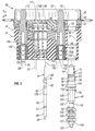
- is a sectional and exploded view of the connector of Fig. 1, showing one large contact and one small contact lying outside the connector body.
- Fig. 4
- is a sectional view of the connector of Fig. 3.
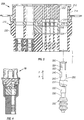
- Fig. 5
- is an exploded sectional view of a connector of another embodiment of the invention, where the large contact is a coaxial contact.
- Figs. 1 and 2 illustrate a
connector 10 which haslarge contacts 12 andsmall contacts 14. The particular large contact assemblies orcontacts 12 are power contacts that carry large currents and therefore require a larger area and larger cross section to minimize heating, while thesmall contacts 14 are signal contacts that carry signals of low current. The contacts mate to contacts of another connector by moving in a forwarddirection F. Wires 20 have front ends terminated to the large contacts and extend rearwardly R from the connector, whilesmaller wires 22 are connected to the smaller contacts and extend rearwardly from the connector. - As shown in Fig. 3, the connector includes a
connector body 30 with arigid insulator 32 that fixes the positions of thecontacts elastomeric seal member 34 that seals to thewires rear parts 40, 42 that are each molded of a rigid engineering polymer, which is a polymer having a Young's modulus of elasticity of at least 100,000 psi. Theseal member 34 is molded of elastomeric material, which is material having a Young's modulus of elasticity of less than 50,000 psi. The front end of the seal member is fixed to the rigid insulator as by adhesive or thermal bonding. - Each large contact assembly or
contact 12 includes a sheetmetal lock ring 60 on a solid machinedpart 61. The contact includes acontact front portion 50 for engaging a mating contact, a rearwardly-facingshoulder 52 and two forwardly-facingshoulders metal ring lock 60 is formed by a piece of sheet metal rolled into a cylinder with a gap indicated at 58. The lock ring has an inwardly angled front end forming a forwardly-facingshoulder 64 that abuts thecontact shoulder 52, and has a lock ringrear shoulder 59 that abuts thecontact shoulder 56. This keeps the lock ring in place on the rest (part 61) of the contact. When a large contact assembly is pushed forwardly into place, theshoulder 59 on the ring lock snaps behind a forwardly-facingshoulder 65 on theinsulator part 42 to prevent contact removal. At the same time, the forwardly-facingshoulder 54 on the contact substantially abuts a rearwardly-facingshoulder 66 formed at a rear surface of the rigid insulator, to prevent any further forward movement of the large contact. - The
rigid insulator 32 has contact-holding passages 70 that receive the large contacts, while theelastomeric seal member 34 hascorresponding seal passages 72 that receive the large contacts and through which thelarge wires 20 extend. - The
small contacts 14 are held in a manner similar to that for the large contacts, with therigid insulator 32 having tines 80 with free front ends forming forwardly-facing shoulders that engage rearwardly-facingshoulders 82 on small contacts. The rigid insulator also forms a rearwardly-facing shoulder 84 that engages a forwardly-facingshoulder 86 of the small contact. Thus, the small contacts, like the large ones, can be installed by sliding them forwardly into place, until resilient shoulders snap behind the rearwardly-facing shoulders of the contacts. - The
small wires 22 each includes acopper core 90 and aninsulator 92 surrounding the core. The front end of the insulator is stripped, thefront end 96 of the core is inserted into asleeve 100 at the rear end of the small contact, and the wire core is terminated to the contact. Termination can be accomplished by crimping thesleeve 100. Another type of sleeve enables soldering of thecore front end 96 to the contact sleeve. The rigid insulator forms small passages 102 that receive the small contacts, while theelastomeric seal member 34 formssmall seal passages 104 through which the contact andsmall wires 22 extend. - The seal member forms
internal ridges 110 that project radially inwardly towards theaxis 112 of the seal passage, to seal to the outside of thewire 22. The internal diameter of the internal ridges results in an interference fit with thewire 22 to provide a moisture-tight seal. The internal diameter is less than the maximum diameter B of the small contact. As a result, insertion of the contact requires it to be pushed forcefully forward through theinternal ridges 110, which are deflected out of the way as the large diameter portions of the contact pass through it. The difference in diameter between the maximum diameter B of the small contact and the diameter D1 of the wire (which is constant) is not great. As a result, the contact can be gently pushed through theinternal ridges 110 to the installed position of the contact, without permanent damage to the internal ridges that would result in the absence of a moisture seal against thesmall wire 22. It is noted that the diameter of thesmall passage 104 in the elastomeric seal member is preferably about equal to the maximum diameter B of the contact, and in almost all cases the diameter of thepassage 104 is at least 95% of the contact maximum diameter B to enable insertion of the contact. - The
large wire 20 includes aninsulator 120 and acopper core 122. The core is terminated to asleeve 124 of the large contact in the same way as for the small contact, as by crimping the sleeve around thefront end 126 of the core. - The
large wire 20 is sealed in place byinternal ridges 130 in the seal passage that lie in interference fit with the large wire. It would be possible to form thelarge ridges 130 integrally with the rest of theseal member 34, as is done for thesmall ridges 110 that seal against the small contacts and wires. However, there would be disadvantages in making the largeinternal ridges 130 integral with theseal member 34. This is because the largest diameter D4 of apart 132 of the large contact is much larger than the diameter D2 of the large wire. As a result, if the large contact part is pushed throughinternal ridges 130 of a diameter to make an interference fit with the large wire, thelarge contact part 54 would cause permanent damage to the ridges, resulting in the considerable possibility that there will not be a watertight seal around the large wire. - To avoid damage to the large
internal ridges 130, applicant forms the largeinternal ridges 130 at the tubular insidesurfaces 134 of elastomeric module inserts 140 that are molded separately from theseal member 34. Amodular insert 140 is slipped onto alarge wire 20 prior to termination of the wire corefront end 126 to the contact. After termination of the wire to the contact, the contact is pushed forwardly throughpassages modular insert 140 is pushed forwardly into the seal passage. It should be noted that the seal member has aninternal flange 150 with a forwardly-facingflange surface 152. Themodular insert 140 is slightly compressed as it is pushed past the flange, until a rearwardly-facinginsert surface 154 at the rear of the insert abuts theflange surface 152. At that time, the insert is slightly compressed against arear end 156 of the contact and theouter surface 158 of the insert lies in an interference fit with the inside of the seal body. The insert is preferably not bonded in place, to permit replacement of a contact. The inside diameter D5 of theseal passage 72 is preferably about the same as the maximum outside diameter D4 of the contact, although it is possible to use aseal passage 72 that is as little as 95% of the maximum contact diameter. - In a connector that applicant has designed, the
small contacts 14 have a largest diameter B of 2,16 mm (85 mils [one mil equals one thousandth inch]), while the small wires have a diameter D1 of 1,22 mm (48 mils), for a ratio of 85/48 = 1.8. Applicant finds that sealing of the smallinternal ridges 110 to the wire can be maintained after the contact is pushed through the ridges, with this ratio of 1.8 of the contact maximum diameter to the wire outside diameter. The large contact had a largest diameter D4 of 5,72 mm (225 mils), while the wire had a diameter D2 of 2,54 mm (100 mils), for a ratio of 225/100 or 2.25:1. Applicant found that internal ridges that could seal to the large wire, would be damaged by passage of the large contact so sealing could not be assured. It appears that when the ratio of contact maximum diameter to wire diameter is more than about 2:1, that applicant's separate modular insert is desirable, while when the ratio is less than 2:1 that the integral internal ridges, which are integral with the rest of the seal member, can be used while providing reliable sealing. Also, when the difference in diameter of 0.225 - 0.100 = 0.125 inch (3.2 mm) is greater than about 0.1 inch (2.5 mm), that a separate modular insert is desirable. For the small contact assembly the difference is only 0.85 - 0.048 = 0.037 inch (0.9 mm). - In the connector that applicant designed, each large seal member passage diameter D5 was 5,77 mm (0.227 inch) which was more than 250% the diameter D6 of each insert internal ridge. Actually, the inside diameter D6 is 1,78 mm (0.07 inch).
- Fig. 5 shows a
connector 200 of another embodiment of the invention, where thelarge contacts 202 are each a coaxial contact with a pin-likecenter contact part 204 and a socket type outercoaxial contact part 206. The connector includes abody 210 with arigid insulator 212 of a molded rigid engineering polymer in each of itsparts elastomeric seal member 220. Therigid insulator 212 haspassages 222 aligned withcorresponding passages 224 in the seal member. A coaxial wire orcable 230 has anouter conductor 232 terminated to the outer contact part, and has acenter conductor 234 terminated to theinner contact part 204. Theouter contact part 206 is of sheet metal, in which slots have been formed to leavetines 240 with rearwardly-facingshoulders 242 that engageshoulders 244 on the rigid insulator. A forwardly-facingshoulder 250 on the contact engages ashoulder 252 on the rigid insulator. An elastomericmodular insert 252 seals thewire 230 to the inside of theseal member passage 224. It is noted that a contact with asocket part 206 is difficult to force through internal seal ridges, and themodular insert 252 is especially useful in this case. - Thus, the invention provides a connector with a rigid insulator and an elastomeric seal member having aligned passages that hold a contact with a wire extending rearwardly from the contact and which seals to the wire, which avoids damage to the seal despite a large difference between the largest diameter of the contact and the diameter of the wire. Where such a large difference exists, damage to the seal is avoided by providing a separate elastic modular insert that is inserted into the seal passage after the contact has been installed. The seal insert can lie in a passage of a connector seal member, which has one or more small passages where the largest diameter of the contact is not that much greater than the outside diameter of the corresponding small wire, and where the seal ridges that press against the outside of the wire are integrally formed with the rest of the seal member instead of being formed as separate inserts. The seal member preferably has an internal flange at the rear of each passage that is to hold a modular insert, and the modular insert is pushed past the flange and thereafter held in place by the flange.
- Although particular embodiments of the invention have been described and illustrated herein, it is recognized that modifications and variations may readily occur to those skilled in the art, and consequently, it is intended that the claims be interpreted to cover such modifications and equivalents.
Claims (10)
- A connector (10, 200) comprising:a connector body (30, 210) that includes a rigid insulator (32, 212) forming a plurality of contact-holding insulator passages (70, 102, 222), said connector body forming a rearwardly-facing shoulder (66, 84, 252) in each insulator passage to limit forward insertion of a contact into the insulator passage, and forming a forwardly-facing shoulder (65, 80, 244) along each insulator passage for retaining the forwardly inserted contact against rearward removal;a plurality of contacts (12, 14, 202) each lying in one of said insulator passages and having forwardly and rearwardly-facing shoulder parts (56, 54, 86, 82, 250, 242) lying substantially against said rearwardly-facing and forwardly-facing shoulders of said connector body, including first and second contacts;a plurality of wires (20, 22, 230), each having a front end joined to one of said contacts and extending rearwardly therefrom, including a first wire (22) joined to said first contact and a second wire (20, 230) joined to said second contact;said connector body includes an elastomeric seal member (34, 220) fixed to said rigid insulator, said seal member having a plurality of seal passages (72, 102, 224) that are each aligned with one of said insulator passages, with said wires passing through said seal passages;said seal member has seal walls that press firmly against at least said first wire (22);a modular elastomeric insert (140, 252) having a tubular inside surface (134) lying in an interference fit with said second wire and having an outside surface (158) lying in an interference fit with a second of said seal passages(72, 224).
- The connector described in claim 1 wherein:said first and second wires (22, 20) each has an outside diameter (D1, D2);said second contact (12) has a front portion that lies in said rigid insulator and immediately behind it, and that has a maximum second contact diameter (D4) that is more than twice the diameter (D2) of the outside of said second wire (20), while the maximum diameter (B) of said first contact (14) is less than twice the diameter (D1) of the outside of said first wire (22).
- The connector described in claim 1 wherein:said second contract (12) has a maximum diameter (D4) that is more than 180% of the outside diameter (D2) of said second wire (20), and that is at least 2 mm greater than the outside diameter of said second wire (20).
- The connector described in at least one of claims 1 to 3 wherein:said second seal passage (72, 224) is cylindrical along its length except at a rear end thereof, and said second seal passage has a radially inwardly-extending flange (150) at said rear end which is of smaller inside diameter than said insert (140, 252) outside diameter.
- The connector described in claim 4 wherein:said insert (140, 252) has a rear end portion with a rearwardly-facing insert surface, and said flange (150) has a forwardly-facing flange surface (152) engaged with said rearwardly-facing insert surface.
- A connector comprising:a rigid insulator (32, 212) forming a plurality of insulator passages (102, 222);a plurality of contacts (12, 14, 202) each lying in one of said insulator passages;a plurality of wires (20, 22, 230) that each has a front end (126, 96, 234) joined to one of said contacts and which extends rearward therefrom and which has a wire outside diameter (D2, B);an elastomeric seal member (34, 220) fixed to said rigid insulator and having a plurality of seal passages (72, 104, 224) that are each aligned with one of said insulator passages, with said wires each passing through one of said seal passages;a first of said wires (20, 230) lies in a first of said seal passages (72, 224) and is connected to a first of said contacts (12, 202) which lies in a first of said insulator passages (70, 222);said first contact (12, 202) has a maximum diameter (D4) which is more than 180% of said first wire (20, 230) outside diameter;said first seal passage (72, 224) has a diameter (D5) along most of its length, which is at least 95% of said first contact maximum diameter (D4) ; and includinga modular elastomeric insert (140, 252) having a tubular inside surface (134) lying in interference fit with said first wire and an outside surface (158) lying in interference fit with said first seal passage.
- The connector described in claim 6 wherein:a second of said wires (22) lies in a second of said seal passages (104) and is mounted to a second of said insulator passages (102);said second contact (14) has a maximum diameter (B) which is greater than said second wire diameter (D1), but with the ratio of said second contact maximum diameter to said second wire diameter being less than the ratio of said first contact maximum diameter to said first wire diameter;said second seal passage (104) has seal passage walls (110) lying in interference fit with second wire (14), with said seal passage walls being integral with said elastomeric seal member (34, 210).
- A connector comprising:a rigid insulator (32, 212) forming a plurality of insulator passages (70, 102, 222) for holding contacts that are connected to front ends of wires;an elastomeric seal member (34, 210) fixed to said rigid insulator and having a plurality of seal passages (72, 104, 224) that are each aligned with one of said insulator passages for passing said contacts;said first seal passage (72) has a predetermined inside diameter (D5) along most of its length, for passing a contact (12) to a first of said insulator passages and for surrounding a first wire; and includinga modular elastomeric insert (140) having a tubular inside surface (134) with a plurality of internal ridges (130) having a minimum diameter to provide an interference fit with said first wire and an outside surface (158) of a diameter to lie in interference fit with said first seal passage;said inside diameter (D5) of said first seal passage is at least 250% of the diameter of said insert inside surface minimum diameter.
- The connector described in claim 8 wherein:said inside diameter (D5) of said first seal passage (72, 224) is at least 2 mm larger than the diameter of said insert inside surface.
- The connector described in claim 8 or 9 wherein:said first seal passage (72, 224) is cylindrical except at its rear end, with said rear end forming a radially inwardly projecting flange (150).
Applications Claiming Priority (2)
| Application Number | Priority Date | Filing Date | Title |
|---|---|---|---|
| US09/611,904 US6325669B1 (en) | 2000-07-06 | 2000-07-06 | Electrical connector sealing system |
| US611904 | 2000-07-06 |
Publications (3)
| Publication Number | Publication Date |
|---|---|
| EP1170829A2 true EP1170829A2 (en) | 2002-01-09 |
| EP1170829A3 EP1170829A3 (en) | 2004-12-15 |
| EP1170829B1 EP1170829B1 (en) | 2006-01-11 |
Family
ID=24450863
Family Applications (1)
| Application Number | Title | Priority Date | Filing Date |
|---|---|---|---|
| EP01115542A Expired - Lifetime EP1170829B1 (en) | 2000-07-06 | 2001-06-28 | Electrical connector with sealing system |
Country Status (8)
| Country | Link |
|---|---|
| US (1) | US6325669B1 (en) |
| EP (1) | EP1170829B1 (en) |
| JP (1) | JP2002042957A (en) |
| KR (1) | KR100397315B1 (en) |
| CN (1) | CN1244971C (en) |
| DE (1) | DE60116548T2 (en) |
| HK (1) | HK1045405B (en) |
| TW (1) | TWI253209B (en) |
Families Citing this family (14)
| Publication number | Priority date | Publication date | Assignee | Title |
|---|---|---|---|---|
| US6929509B2 (en) * | 2002-03-21 | 2005-08-16 | Komax Holding Ag | Method and device for sealing off channels of electric connectors |
| FR2844644B1 (en) * | 2002-09-12 | 2006-04-28 | Framatome Connectors Int | SEALING SYSTEM FOR MULTI-SPINDLE ELECTRICAL CONNECTOR |
| JP2007035362A (en) * | 2005-07-25 | 2007-02-08 | Tyco Electronics Amp Kk | Sealing member and waterproof type connector |
| US8241061B2 (en) * | 2006-01-19 | 2012-08-14 | Fci Automotive Holding | Obturator for a compartment of a junction unit and junction unit equipped with such a obturator |
| CN100459302C (en) * | 2007-07-05 | 2009-02-04 | 中航光电科技股份有限公司 | Plug sealing structure of underwater electrical connector contact part |
| JP2008204960A (en) * | 2008-05-28 | 2008-09-04 | Sumitomo Wiring Syst Ltd | Waterproof connector |
| JP5353676B2 (en) * | 2009-12-16 | 2013-11-27 | 住友電装株式会社 | connector |
| DE102009054854A1 (en) * | 2009-12-17 | 2011-06-22 | Robert Bosch GmbH, 70469 | Plug arrangement and sealing device for at least one, in particular electrical line |
| JP5700076B2 (en) * | 2012-12-03 | 2015-04-15 | 株式会社デンソー | Terminal manufacturing method and terminal |
| CN102983437B (en) * | 2012-12-14 | 2015-09-16 | 东莞市泽润电子科技有限公司 | Volume nose circle and manufacture method thereof |
| FR3012689B1 (en) * | 2013-10-29 | 2017-06-23 | Molex Inc | ELECTRICAL CONNECTOR WITH MOBILE SKIRT |
| JP6295100B2 (en) * | 2014-02-28 | 2018-03-14 | 日立オートモティブシステムズ株式会社 | Electronic control unit |
| WO2019232386A1 (en) * | 2018-05-31 | 2019-12-05 | Hydra-Electric Company | Method of sealing cable exit for moisture and vapor intrusion |
| US11791571B2 (en) * | 2020-06-26 | 2023-10-17 | Ge Aviation Systems Llc | Crimp pin electrical connector |
Citations (6)
| Publication number | Priority date | Publication date | Assignee | Title |
|---|---|---|---|---|
| US4084875A (en) * | 1975-01-10 | 1978-04-18 | International Telephone And Telegraph Corporation | Electrical connector |
| DE19548503A1 (en) * | 1995-12-22 | 1997-06-26 | Whitaker Corp | High efficiency seal using high viscosity fluid e.g. for plug housing |
| US5989065A (en) * | 1995-05-05 | 1999-11-23 | The Boeing Company | High performance Mil-C-26500 |
| EP0971452A2 (en) * | 1998-07-06 | 2000-01-12 | Yazaki Corporation | Waterproof connector and waterproof rubber member |
| EP0989633A2 (en) * | 1998-09-25 | 2000-03-29 | The Whitaker Corporation | Cam slide electrical connector |
| FR2786033A1 (en) * | 1998-11-17 | 2000-05-19 | Whitaker Corp | Electric/fibre optic connector wire sealing technique having outer sleeving wire covering and forming connector interface seal |
Family Cites Families (18)
| Publication number | Priority date | Publication date | Assignee | Title |
|---|---|---|---|---|
| US3710003A (en) | 1971-04-16 | 1973-01-09 | W Channell | Connecting block and housing for use in underground residential power distribution |
| US3787796A (en) | 1972-10-17 | 1974-01-22 | Itt | Low cost sealed connector and method of making same |
| US3848074A (en) | 1973-04-13 | 1974-11-12 | W Channell | Terminal and splice enclosure for cable installations |
| US3880487A (en) | 1973-07-20 | 1975-04-29 | Itt | Low cost sealed connector |
| US4173349A (en) | 1978-08-24 | 1979-11-06 | General Motors Corporation | Connector interface sealing arrangement |
| US4241967A (en) | 1979-08-31 | 1980-12-30 | The Bendix Corporation | Electrical connector assembly sealing grommet |
| US4681691A (en) | 1985-05-17 | 1987-07-21 | Amp Incorporated | Moldable composition |
| US4713021A (en) | 1985-05-17 | 1987-12-15 | Amp Incorporated | Sealed electrical connector and method of using same |
| US4921437A (en) | 1989-03-29 | 1990-05-01 | Amp Incorporated | Sealed electrical connector assembly with terminal retainer |
| US4993964A (en) * | 1989-04-18 | 1991-02-19 | Martin Marietta Corporation | Electrical connector environmental sealing plug |
| US4998896A (en) | 1989-09-25 | 1991-03-12 | Amp Incorporated | Sealed stamped and formed pin |
| US4981446A (en) * | 1989-11-06 | 1991-01-01 | The Boeing Company | Modular, circular, environment resistant electrical connector assembly |
| US5035638A (en) | 1990-08-16 | 1991-07-30 | Amp Incorporated | Electrical terminal which has means to provide a reliable electrical connection |
| CA2080585C (en) | 1991-02-15 | 2001-12-18 | Hugues Fortin | Electrical connector with sealing feed-through |
| US5607318A (en) | 1993-11-05 | 1997-03-04 | Sumitomo Wiring Systems, Ltd. | Waterproof connector |
| US5709560A (en) * | 1994-12-14 | 1998-01-20 | Sumitomo Wiring Systems, Ltd. | Connector having a pivotable connection-assistance member |
| JPH09289057A (en) * | 1996-04-19 | 1997-11-04 | Yazaki Corp | Waterproof connector |
| JP3540156B2 (en) * | 1998-06-10 | 2004-07-07 | 矢崎総業株式会社 | Waterproof connector and method of assembling the waterproof connector |
-
2000
- 2000-07-06 US US09/611,904 patent/US6325669B1/en not_active Expired - Fee Related
-
2001
- 2001-05-17 TW TW090111846A patent/TWI253209B/en not_active IP Right Cessation
- 2001-06-20 CN CNB011216441A patent/CN1244971C/en not_active Expired - Fee Related
- 2001-06-28 EP EP01115542A patent/EP1170829B1/en not_active Expired - Lifetime
- 2001-06-28 DE DE60116548T patent/DE60116548T2/en not_active Expired - Fee Related
- 2001-06-29 KR KR10-2001-0038205A patent/KR100397315B1/en not_active IP Right Cessation
- 2001-07-06 JP JP2001206209A patent/JP2002042957A/en active Pending
-
2002
- 2002-07-09 HK HK02105110.2A patent/HK1045405B/en not_active IP Right Cessation
Patent Citations (6)
| Publication number | Priority date | Publication date | Assignee | Title |
|---|---|---|---|---|
| US4084875A (en) * | 1975-01-10 | 1978-04-18 | International Telephone And Telegraph Corporation | Electrical connector |
| US5989065A (en) * | 1995-05-05 | 1999-11-23 | The Boeing Company | High performance Mil-C-26500 |
| DE19548503A1 (en) * | 1995-12-22 | 1997-06-26 | Whitaker Corp | High efficiency seal using high viscosity fluid e.g. for plug housing |
| EP0971452A2 (en) * | 1998-07-06 | 2000-01-12 | Yazaki Corporation | Waterproof connector and waterproof rubber member |
| EP0989633A2 (en) * | 1998-09-25 | 2000-03-29 | The Whitaker Corporation | Cam slide electrical connector |
| FR2786033A1 (en) * | 1998-11-17 | 2000-05-19 | Whitaker Corp | Electric/fibre optic connector wire sealing technique having outer sleeving wire covering and forming connector interface seal |
Also Published As
| Publication number | Publication date |
|---|---|
| TWI253209B (en) | 2006-04-11 |
| EP1170829B1 (en) | 2006-01-11 |
| DE60116548T2 (en) | 2006-11-09 |
| EP1170829A3 (en) | 2004-12-15 |
| US6325669B1 (en) | 2001-12-04 |
| CN1244971C (en) | 2006-03-08 |
| JP2002042957A (en) | 2002-02-08 |
| HK1045405A1 (en) | 2002-11-22 |
| CN1332493A (en) | 2002-01-23 |
| HK1045405B (en) | 2006-11-03 |
| DE60116548D1 (en) | 2006-04-06 |
| KR20020006580A (en) | 2002-01-23 |
| KR100397315B1 (en) | 2003-09-06 |
Similar Documents
| Publication | Publication Date | Title |
|---|---|---|
| US4986764A (en) | High voltage lead assembly and connector | |
| US6325669B1 (en) | Electrical connector sealing system | |
| US3787796A (en) | Low cost sealed connector and method of making same | |
| US5389005A (en) | Waterproof electric connector seal member | |
| US7070463B2 (en) | Waterproof relay connector | |
| US6450829B1 (en) | Snap-on plug coaxial connector | |
| US4362350A (en) | Contact retention assembly | |
| US7311546B2 (en) | Connector, a mating connector and a connector device | |
| US5890930A (en) | Replaceable contact connector | |
| US5704809A (en) | Coaxial electrical connector | |
| EP0221952B1 (en) | Wire seal | |
| US4768970A (en) | Electrical connector plug assembly for sealed electrical connection | |
| US6840804B2 (en) | Fitting structure of waterproof plug | |
| US5766039A (en) | Waterproof connector with pressing holes in seal member | |
| GB2134724A (en) | Electrical connector having terminal housing retaining member | |
| US5135417A (en) | Dual usage electrical/electronic pin terminal system | |
| US4708666A (en) | Triaxial to coaxial connector assembly | |
| CA2097979C (en) | Female electrical contact terminal for a connector | |
| US4221446A (en) | Electrical connector assembly | |
| US5035638A (en) | Electrical terminal which has means to provide a reliable electrical connection | |
| US4220385A (en) | Electrical connector | |
| US3845459A (en) | Dielectric sleeve for electrically and mechanically protecting exposed female contacts of an electrical connector | |
| EP0402451B1 (en) | Electrical terminal which has means to provide a reliable electrical connection | |
| EP1028486A3 (en) | Electrical connector terminal | |
| US6142795A (en) | Electrical connector with grounded contact |
Legal Events
| Date | Code | Title | Description |
|---|---|---|---|
| PUAI | Public reference made under article 153(3) epc to a published international application that has entered the european phase |
Free format text: ORIGINAL CODE: 0009012 |
|
| AK | Designated contracting states |
Kind code of ref document: A2 Designated state(s): AT BE CH CY DE DK ES FI FR GB GR IE IT LI LU MC NL PT SE TR |
|
| AX | Request for extension of the european patent |
Free format text: AL;LT;LV;MK;RO;SI |
|
| PUAL | Search report despatched |
Free format text: ORIGINAL CODE: 0009013 |
|
| AK | Designated contracting states |
Kind code of ref document: A3 Designated state(s): AT BE CH CY DE DK ES FI FR GB GR IE IT LI LU MC NL PT SE TR |
|
| AX | Request for extension of the european patent |
Extension state: AL LT LV MK RO SI |
|
| 17P | Request for examination filed |
Effective date: 20050111 |
|
| GRAP | Despatch of communication of intention to grant a patent |
Free format text: ORIGINAL CODE: EPIDOSNIGR1 |
|
| AKX | Designation fees paid |
Designated state(s): DE FR GB |
|
| GRAS | Grant fee paid |
Free format text: ORIGINAL CODE: EPIDOSNIGR3 |
|
| GRAA | (expected) grant |
Free format text: ORIGINAL CODE: 0009210 |
|
| AK | Designated contracting states |
Kind code of ref document: B1 Designated state(s): DE FR GB |
|
| REF | Corresponds to: |
Ref document number: 60116548 Country of ref document: DE Date of ref document: 20060406 Kind code of ref document: P |
|
| ET | Fr: translation filed | ||
| REG | Reference to a national code |
Ref country code: HK Ref legal event code: GR Ref document number: 1045405 Country of ref document: HK |
|
| PLBE | No opposition filed within time limit |
Free format text: ORIGINAL CODE: 0009261 |
|
| STAA | Information on the status of an ep patent application or granted ep patent |
Free format text: STATUS: NO OPPOSITION FILED WITHIN TIME LIMIT |
|
| 26N | No opposition filed |
Effective date: 20061012 |
|
| PGFP | Annual fee paid to national office [announced via postgrant information from national office to epo] |
Ref country code: FR Payment date: 20090617 Year of fee payment: 9 |
|
| PGFP | Annual fee paid to national office [announced via postgrant information from national office to epo] |
Ref country code: DE Payment date: 20090629 Year of fee payment: 9 Ref country code: GB Payment date: 20090625 Year of fee payment: 9 |
|
| GBPC | Gb: european patent ceased through non-payment of renewal fee |
Effective date: 20100628 |
|
| REG | Reference to a national code |
Ref country code: FR Ref legal event code: ST Effective date: 20110228 |
|
| PG25 | Lapsed in a contracting state [announced via postgrant information from national office to epo] |
Ref country code: DE Free format text: LAPSE BECAUSE OF NON-PAYMENT OF DUE FEES Effective date: 20110101 |
|
| PG25 | Lapsed in a contracting state [announced via postgrant information from national office to epo] |
Ref country code: FR Free format text: LAPSE BECAUSE OF NON-PAYMENT OF DUE FEES Effective date: 20100630 |
|
| PG25 | Lapsed in a contracting state [announced via postgrant information from national office to epo] |
Ref country code: GB Free format text: LAPSE BECAUSE OF NON-PAYMENT OF DUE FEES Effective date: 20100628 |