EP1170736A2 - Pickup device - Google Patents
Pickup device Download PDFInfo
- Publication number
- EP1170736A2 EP1170736A2 EP01115491A EP01115491A EP1170736A2 EP 1170736 A2 EP1170736 A2 EP 1170736A2 EP 01115491 A EP01115491 A EP 01115491A EP 01115491 A EP01115491 A EP 01115491A EP 1170736 A2 EP1170736 A2 EP 1170736A2
- Authority
- EP
- European Patent Office
- Prior art keywords
- objective lens
- recording medium
- information recording
- contact portion
- optical information
- Prior art date
- Legal status (The legal status is an assumption and is not a legal conclusion. Google has not performed a legal analysis and makes no representation as to the accuracy of the status listed.)
- Granted
Links
Images






Classifications
-
- G—PHYSICS
- G11—INFORMATION STORAGE
- G11B—INFORMATION STORAGE BASED ON RELATIVE MOVEMENT BETWEEN RECORD CARRIER AND TRANSDUCER
- G11B7/00—Recording or reproducing by optical means, e.g. recording using a thermal beam of optical radiation by modifying optical properties or the physical structure, reproducing using an optical beam at lower power by sensing optical properties; Record carriers therefor
- G11B7/12—Heads, e.g. forming of the optical beam spot or modulation of the optical beam
- G11B7/121—Protecting the head, e.g. against dust or impact with the record carrier
-
- G—PHYSICS
- G11—INFORMATION STORAGE
- G11B—INFORMATION STORAGE BASED ON RELATIVE MOVEMENT BETWEEN RECORD CARRIER AND TRANSDUCER
- G11B7/00—Recording or reproducing by optical means, e.g. recording using a thermal beam of optical radiation by modifying optical properties or the physical structure, reproducing using an optical beam at lower power by sensing optical properties; Record carriers therefor
- G11B7/08—Disposition or mounting of heads or light sources relatively to record carriers
- G11B7/09—Disposition or mounting of heads or light sources relatively to record carriers with provision for moving the light beam or focus plane for the purpose of maintaining alignment of the light beam relative to the record carrier during transducing operation, e.g. to compensate for surface irregularities of the latter or for track following
- G11B7/0908—Disposition or mounting of heads or light sources relatively to record carriers with provision for moving the light beam or focus plane for the purpose of maintaining alignment of the light beam relative to the record carrier during transducing operation, e.g. to compensate for surface irregularities of the latter or for track following for focusing only
Definitions
- the present invention relates to a pickup device for recording or reproducing information to or from an optical information recording medium, such as an optical disc, recorded with information on the track. More particularly, the invention relates to a buffer pad attached to an objective lens or a driving part used in the pickup device.
- the optical discs of the optical information recording media are broadly used as means for recording and reproducing data such as images and sound.
- data such as images and sound.
- the numerical aperture for example is given 0.45 for the CD (Compact Disc) and 0.6 for the DVD (Digital Versatile Disc).
- the effective diameter of the objective lens has decreased from nearly 4.5 mm in the conventional to nearly 3 mm.
- the working distance of between the tip end of the objective lens and the surface of the optical disc has been decreased.
- the thickness of the transmissive substrate while 1.2 mm for the CD, is 0.6 mm for the DVD. Because the distance is shortened to the recording surface protected by the transmissive substrate, there is increased influence upon the signal based on the injury on the optical disc surface caused by collision of the objective lens.
- DVD-RW Digital Versatile Disc-Rewritable
- a focus servo and a tracking servo are essential for always accurately converging light beams for writing and reading information to a pit train or the like formed spirally or concentrically on a recording surface of the optical disc.
- the focus servo performs a positional control for an objective lens, used to irradiate a pit train on the optical disc with light beams, in an optical axis direction so as to reduce a focus error, i.e., an error of the position of the objective lens in the optical axis direction with respect to the focus position of the objective lens.
- the tracking servo performs a positional control for the position of the objective lens, used to irradiate a pit train on the optical disc with light beams, with respect to a recording track in a radial direction of the optical disc, so as to reduce a tracking error, i.e., an error of the objective lens with respect to the pit train recording track position.
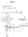
- Fig. 1 illustrates a conventional optical pickup device using an astigmatism method.
- a laser beam from a semiconductor laser 1 is transformed into a parallel laser beam by a collimator lens 2, passes through a polarizing beam splitter 3 and a 1/4 wavelength plate 18, and is converged by an objective lens 4 toward an optical disc 5 to form a light spot onto a pit train on an information recording surface of the optical disc 5.
- a detecting lens 7 Light reflected from the optical disc 5 is converged by the objective lens 4 and directed by a beam splitter 3 to a detecting lens 7. Converged light formed by the detecting lens 7 passes through an astigmatism generating element 8 such as a cylindrical lens, multi lens and the like, to form a spot near the center 'O' of a light receiving surface of a quadrant photodetector 9 having four light-receiving surface areas (elements) divided by two orthogonal line segments.
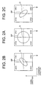
- the multi lens 8 irradiates the quadrant photodetector 9 with a light spot SP in the shape of true circle as illustrated in Fig.
- FIG. 2A when the laser beam is converged on the recording surface of the optical disc 5 in focus, and an elliptic light spot SP, extending in an orthogonal direction of the elements as illustrated in Fig. 2B or 2C when the converged laser beam is out of focus on the recording surface of the optical disc 5
- Fig. 2B illustrates the light spot SP when the objective lens 4 is too far from the optical disc 5
- Fig. 2C illustrates the light spot SP when the objective lens 4 is too near the optical disc 5 shown in Fig. 1
- the quadrant photodetector 9 opto-electrically transduces the light spot irradiated to the four light receiving surface areas into respective electric signals which are supplied to a focus error detecting circuit 12.
- the focus error detecting circuit 12 generates a focus error signal (FES) based on the electric signals supplied from the quadrant photodetector 9 and supplies the focus error signal to an actuator driver circuit 13.
- the actuator driver circuit 13 supplies a focusing driving signal to an actuator 15.
- the actuator 15 drives the objective lens 4 in response to the focusing driving signal in the optical axis direction.
- the focus error detecting circuit 12, as illustrated in Fig. 3, is connected to the quadrant photodetector 9, where the quadrant photodetector 9 is composed of four detecting elements DET1 to DET4 in first to fourth quadrants which are located adjacent to each other with two orthogonal division lines L1 and L2 interposed therebetween and which are independent of each other.
- the quadrant photodetector 9 is positioned such that the division line L2 is in parallel with a tangential direction with respect to the extending direction of the recording track, and the other division line L1 is in parallel with the radial direction of the same.
- Respective opto-electrically transduced outputs from the elements DET1 and DET3, symmetric with respect to the center 'O' of the light receiving surface of the quadrant photodetector 9, are added by an adder 22, while respective opto-electrically transduced outputs from the elements DET2 and DET4, also symmetric with respect to the center 'O' of the light receiving surface, are added by an adder 21, and outputs from the respective adders 21 and 22 are supplied to a differential amplifier 23.
- the differential amplifier 23 calculates the difference between the supplied signals, and outputs a signal indicative of the difference therebetween as a focus error signal (FES).
- FES focus error signal
- the outputs of the quadrant photodetector 9 are added by the adders 21 and 22, respectively, and the differential amplifier 23 calculates the difference between the outputs of the adders 21 and 22 to generate a focus error component.
- the light spot in the shape of true circle as illustrated in Fig.
- a spot intensity distribution is symmetric with respect to the center 'O' of the light receiving surface of the quadrant photodetector 9, i.e., symmetric in the tangential direction and in the radial direction, so that the values resulting from the additions of the opto-electrically transduced outputs from the elements on the diagonals are equal to each other, with the focus error component being calculated to be "zero".
- the light beam is out of focus, i.e., an elliptic light spot extending in a diagonal direction as illustrated in Fig.
- the focus error component output from the differential amplifier 23 exhibits a value corresponding to the focus error.
- the light spot on the photodetector is disturbed in shape by the influence thereof.
- a pseudo focus error signal occurs having the same polarity as that of the optical disc in far distance in focus servo system.
- the pseudo focus error signal causes current flow to a driving mechanism for the objective-lens of a drive part in the pickup device. As a result, the objective lens may be driven forcibly toward the optical disc.
- the objective lens is contacted with the optical-disc surface repeatedly in a particular track position. With such contact, the surface area the light beam passes is injured when the objective lens traces the track area, inducing further contact occurrence. This results in a problem that signal recording or reproducing to or from the track is difficult.
- the present invention has been made in view of the foregoing points, and it is an object to provide a pickup device having a collision preventive function capable of suppressing the spread of damage caused due to collision between the objective lens and the optical-disc surface.
- a device is a pickup device in an apparatus for performing recording or reproducing, with relative movement, to or from an optical information recording medium recorded with information on a track, which comprises:
- said optical information recording medium is an optical disc recorded with information concerning said optical information recording medium in a lead-in or lead-out region existing in an inner periphery or outer periphery thereof, said contact portion being positioned on an inner or outer side of said lead-in or lead-out region of said optical disc when said objective lens focuses a light beam to said lead-in or lead-out region.
- the collision preventing device i.e., buffer pad is provided in the vicinity of the objective lens to structure a protection pad for contact avoiding the track area to be read, in which the non-contact portion of the buffer pad is not contacted with an area of the surface of the disc within an effective diameter of the light spot on the track (in this paper, such area is also referred merely to as "effective diameter") under recording or reproducing.
- effective diameter an effective diameter of the light spot on the track
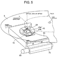
- Fig. 5 shows a first embodiment of an optical pickup device using an example of a collision preventive mechanism based on the invention.
- 50 is a pickup main body unit
- 4 is an objective lens
- 15 is an objective lens-driving part for driving the objective lens
- 43 is a buffer pad based on the invention
- 43a is a contact portion of the buffer pad
- 43b is a non-contact portion of a recess of the buffer pad or the like
- 5 is an optical disc.
- 28 shows a light spot on the optical disc formed by a light beam during recording or reproducing (such a light spot has an area within the "effective diameter").
- the buffer pad 43 of the invention is formed using a material lower in hardness than the light transmissive layer on the recording surface of the optical disc 5.
- the buffer pad 43 as an annular flat plate, includes a contact portion 43a to be brought into contact with a surface of the optical disc 5 earlier than the objective lens 4 when the objective lens 4 comes near the surface of the optical disc 5, and a non-contact portion 43b provided adjacent the contact portion and not to be contacted with the surface of the optical disc 5 in an area corresponding to a path 28a of a light spot defined by a diameter of the light spot 28 of the light beam on the track.
- the optical pickup device has an objective lens 4 and a main body unit 50.
- the main body unit 50 includes a light source such as a semiconductor laser for emitting a light beam, and further has a detecting optical system including an illuminating optical system for guiding a light beam to the objective lens and light detecting means to guide the reflection light from the optical disc to the light detecting means through the objective lens.
- an elastic support member such as a leaf spring for supporting the objective lens 4 on the main body unit 50 and an objective lens drive part 15 such as an actuator for driving the objective lens 4 in a radial direction and focusing direction of the optical disc in order to focus the optical beam toward an information recording surface of the optical disc 5.
- the objective lens supported by the elastic support member is attached in a holder.
- the objective lens drive mechanism has a coil, cooperating with the holder to extend in the radial direction and focusing direction, and a magnetic circuit.
- the main body unit 50 is fixed on a slider 70 moving over a shaft 60 extending in the radial direction of the optical disc 5.
- the slider 70 allows the main body unit 50 to roughly move in the radial direction of the optical disc 5.
- the main body unit 50 has, therein, an illuminating optical system formed by a semiconductor laser for emitting linear polarization light, a collimator lens, a polarization light beam splitter, a 1/4-wavelength plate and a rising reflection mirror, and a detecting optical system having an astigmatism generating element formed by a rising reflection mirror, a 1/4-wavelength plate, polarization light beam splitter, a detecting lens system, etc. and a quadrant photodetector, although these are not shown.
- an illuminating optical system formed by a semiconductor laser for emitting linear polarization light, a collimator lens, a polarization light beam splitter, a 1/4-wavelength plate and a rising reflection mirror, and a detecting optical system having an astigmatism generating element formed by a rising reflection mirror, a 1/4-wavelength plate, polarization light beam splitter, a detecting lens system, etc. and a quadrant photodetector, although these are not shown.
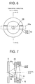
- the objective lens 4 as shown in Fig. 7 is controlled in position relative to the optical disc 5 by the focus servo mechanism, to keep a predetermined working distance between a top end surface of the contact portion 43a of the buffer pad and a surface of the optical disc.
- the working distance of the objective lens is, for example, nearly 100 ⁇ m.
- the buffer pad 43 is provided with the non-contact portion 43b in a recess form or the like to avoid the pad from contacting within a path 28a of the light spot reading the track. Due to this, there is no increase of flaw on the track surface as a cause of pseudo focus error. Also, there is no further deterioration of a pseudo error signal caused due to bubbles in the transparent layer on the recording surface.
- the contact area on the contact portion 43a of the buffer pad can be provided broad. Accordingly, in the absence of a flaw, there is slight effect upon signal recording or reproducing outside the light-spot path. This will provide a great effect for the case that focus servo is placed unstable by flawing further to the flawed light-spot path.
- Fig. 8 is the second example having such a form that a buffer pad contacts on an inner peripheral side of the objective lens.
- 43 is a buffer pad based on the invention
- a contact portion 43a is an abutting part of the buffer pad
- 29 shows an innermost track position of the optical disc.
- the contact portion 43a is in such a position further on an inner side of the innermost track position 29.
- the optical disc such as CD and DVD, has an area called a lead-in area or TOC area (collectively referred to as a lead-in area) in the innermost peripheral area 29 to record information representative of an outline on an optical disc kind or content.
- This area is first reproduced to acquire required information for recording to or reproducing from the optical disc. That is, in some conventional structures, this innermost peripheral area is readily injured due to contact. Required information is not available depending on a degree of injury, resulting in occurrence of impossibility to use the entire optical disc.
- the distance D between an objective-lens center position X in a disc radial direction and a position of a buffer-pad contact portion 43a is set great on an inner peripheral side than a distance of between a performance starting track position In for reproducing the first information and a signal recording innermost peripheral position 29. That is, the contact portion 43a is selected in shape such that the contact position that contact have occurred in reading a track for first reproducing information is positioned inward of the information recording area. Accordingly, even if contact occurs upon first performing retraction, the information area is not injured. Thus, there is no adverse affection in reading signals from then on.
- the contact portion 43a of the buffer pad is arranged such that that is positioned in an outer periphery than the lead-in area when the objective lens 4 is focusing a light beam onto the lead-in area.
- the buffer pad of the invention may be designed in shape such that a colliding part does not exist in a path of a light spot of reading the track.
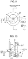
- various shapes of structures are possible, as shown in Figs . 7 to 10, i.e.
- the contact portion 43a may be on an inner peripheral side of an innermost track position 29. Accordingly, various shapes are to be structured as other embodiment as shown in Figs. 15 to 18, i.e.
- the pad in the first example the pad may be mounted inclined in a disc radial direction toward an arbitrary direction excepting the light-spot path on a tangential line in a disc radial direction without changing the thickness of the buffer pad, as shown in Fig. 19. Also, in the second example, it is possible to structure as shown in Fig. 20 such that the buffer pad 43 at an inner peripheral side first comes into collision.
- the invention even where the objective lens collides with an optical disc, the injury in the problematic point will not be deepened, suppressing the damage from spreading.
- the invention exhibits a great effect upon recording and reproducing to and from the optical disc ready to undergo affection such as of injury particularly due to density increase.
Landscapes
- Physics & Mathematics (AREA)
- Optics & Photonics (AREA)
- Optical Head (AREA)
- Optical Recording Or Reproduction (AREA)
Abstract
Description
Claims (2)
- A pickup device in an apparatus for performing recording or reproducing, with relative movement, to or from an optical information recording medium recorded with information on a track, comprising:an objective lens for focusing a light beam to a track on a recording surface of an optical information recording medium;a drive part supporting said objective lens to control a position thereof relatively to said optical information recording medium; anda collision preventive device provided on said objective lens or drive part to prevent direct contact between said objective lens and a surface of said optical information recording medium; whereinsaid collision preventive device includes a contact portion to be contacted with the surface of said optical information recording medium earlier than said objective lens when said objective lens approaches the surface of said optical information recording medium, and a non-contact portion provided adjacent said contact portion not to be contacted with the surface of said optical information recording medium in an area corresponding to a path of a light spot defined by a diameter of said light spot of a light beam on said track.
- A pickup device according to claim 1, wherein said optical information recording medium is an optical disc recorded with information concerning said optical information recording medium in a lead-in or lead-out region existing in an inner periphery or outer periphery thereof, said contact portion being positioned on an inner or outer side of said lead-in or lead-out region of said optical disc when said objective lens focuses a light beam to said lead-in or lead-out region.
Applications Claiming Priority (2)
| Application Number | Priority Date | Filing Date | Title |
|---|---|---|---|
| JP2000203822 | 2000-07-05 | ||
| JP2000203822A JP4141622B2 (en) | 2000-07-05 | 2000-07-05 | Pickup device |
Publications (3)
| Publication Number | Publication Date |
|---|---|
| EP1170736A2 true EP1170736A2 (en) | 2002-01-09 |
| EP1170736A3 EP1170736A3 (en) | 2004-04-21 |
| EP1170736B1 EP1170736B1 (en) | 2006-11-08 |
Family
ID=18701184
Family Applications (1)
| Application Number | Title | Priority Date | Filing Date |
|---|---|---|---|
| EP01115491A Expired - Lifetime EP1170736B1 (en) | 2000-07-05 | 2001-06-27 | Pickup device |
Country Status (5)
| Country | Link |
|---|---|
| US (1) | US6542454B2 (en) |
| EP (1) | EP1170736B1 (en) |
| JP (1) | JP4141622B2 (en) |
| CN (1) | CN1181480C (en) |
| DE (1) | DE60124347T2 (en) |
Cited By (3)
| Publication number | Priority date | Publication date | Assignee | Title |
|---|---|---|---|---|
| WO2004015694A3 (en) * | 2002-08-05 | 2004-05-21 | Koninkl Philips Electronics Nv | Scanning device including an objective system with a lens protection device |
| EP1548717A4 (en) * | 2002-09-30 | 2007-03-28 | Pioneer Corp | Optical disk reproducing device, object lens, protection member and optical disk reproducing method |
| EP1209670A3 (en) * | 2000-11-22 | 2007-05-30 | Sony Corporation | Optical pickup apparatus and disk drive apparatus |
Families Citing this family (10)
| Publication number | Priority date | Publication date | Assignee | Title |
|---|---|---|---|---|
| JP4016667B2 (en) * | 2002-02-15 | 2007-12-05 | ヤマハ株式会社 | Optical disc apparatus, focus control method and program |
| JP2005151676A (en) * | 2003-11-14 | 2005-06-09 | Mitsubishi Fuso Truck & Bus Corp | Sensor harness fixing structure |
| JP3892444B2 (en) * | 2004-03-01 | 2007-03-14 | シャープ株式会社 | Objective lens driving device and optical pickup device using the same |
| JP2006155825A (en) * | 2004-11-30 | 2006-06-15 | Sharp Corp | Lens support mechanism, optical pickup device, and recording / reproducing device |
| JPWO2006098361A1 (en) * | 2005-03-17 | 2008-08-28 | 松下電器産業株式会社 | Optical pickup device and optical disk device |
| JP2007018632A (en) * | 2005-07-08 | 2007-01-25 | Sharp Corp | Objective lens holding device and use thereof |
| JP4717074B2 (en) * | 2005-10-14 | 2011-07-06 | パイオニア株式会社 | Collision prevention mechanism and manufacturing method thereof |
| JP2008047258A (en) * | 2006-08-21 | 2008-02-28 | Funai Electric Co Ltd | Optical pickup device |
| JP2008210458A (en) * | 2007-02-27 | 2008-09-11 | Funai Electric Co Ltd | Objective lens actuator and optical pickup device with same |
| US20090077627A1 (en) * | 2007-03-16 | 2009-03-19 | Novell, Inc. | Information card federation point tracking and management |
Family Cites Families (5)
| Publication number | Priority date | Publication date | Assignee | Title |
|---|---|---|---|---|
| JPH0276128A (en) * | 1988-09-13 | 1990-03-15 | Pioneer Electron Corp | Method for pulling-in focus servo |
| JP3172639B2 (en) * | 1994-10-03 | 2001-06-04 | シャープ株式会社 | Disk recording device |
| US5995304A (en) * | 1997-07-02 | 1999-11-30 | Fuji Photo Optical Co., Ltd. | Plastic lens |
| JPH1123808A (en) * | 1997-07-02 | 1999-01-29 | Fuji Photo Optical Co Ltd | Plastic lens |
| JP3845982B2 (en) * | 1997-10-17 | 2006-11-15 | ソニー株式会社 | Optical pickup device |
-
2000
- 2000-07-05 JP JP2000203822A patent/JP4141622B2/en not_active Expired - Fee Related
-
2001
- 2001-06-27 DE DE60124347T patent/DE60124347T2/en not_active Expired - Lifetime
- 2001-06-27 EP EP01115491A patent/EP1170736B1/en not_active Expired - Lifetime
- 2001-07-03 US US09/897,413 patent/US6542454B2/en not_active Expired - Fee Related
- 2001-07-05 CN CNB011159960A patent/CN1181480C/en not_active Expired - Fee Related
Cited By (3)
| Publication number | Priority date | Publication date | Assignee | Title |
|---|---|---|---|---|
| EP1209670A3 (en) * | 2000-11-22 | 2007-05-30 | Sony Corporation | Optical pickup apparatus and disk drive apparatus |
| WO2004015694A3 (en) * | 2002-08-05 | 2004-05-21 | Koninkl Philips Electronics Nv | Scanning device including an objective system with a lens protection device |
| EP1548717A4 (en) * | 2002-09-30 | 2007-03-28 | Pioneer Corp | Optical disk reproducing device, object lens, protection member and optical disk reproducing method |
Also Published As
| Publication number | Publication date |
|---|---|
| CN1181480C (en) | 2004-12-22 |
| EP1170736B1 (en) | 2006-11-08 |
| EP1170736A3 (en) | 2004-04-21 |
| US6542454B2 (en) | 2003-04-01 |
| DE60124347T2 (en) | 2007-05-24 |
| JP2002025094A (en) | 2002-01-25 |
| US20020039342A1 (en) | 2002-04-04 |
| JP4141622B2 (en) | 2008-08-27 |
| CN1337686A (en) | 2002-02-27 |
| DE60124347D1 (en) | 2006-12-21 |
Similar Documents
| Publication | Publication Date | Title |
|---|---|---|
| KR100803710B1 (en) | Optical pickup unit and disk drive unit | |
| EP1170736B1 (en) | Pickup device | |
| JP2000171346A (en) | Aberration detection device and optical pickup device | |
| JP2002150598A (en) | Optical pickup device and recording / reproducing device | |
| CN101978423B (en) | Optical head and optical information device | |
| KR100189899B1 (en) | Optical disc perception method having different thickness and optical apparatus using it | |
| JP2003016672A (en) | Optical head device and optical head control device | |
| EP0745979A2 (en) | Optical pickup apparatus having objective lens positioning system | |
| US5559771A (en) | Tracking control apparatus and optical pickup having the same | |
| US20080267020A1 (en) | Optical disc apparatus and focus control method | |
| EP1965379A1 (en) | Objective lens actuator and optical pickup device including the same | |
| US20070286055A1 (en) | Optical pickup apparatus and information recording/reproduction apparatus | |
| JP4807398B2 (en) | Optical pickup | |
| JPH1116186A (en) | Optical pickup device | |
| JP2002055024A (en) | Aberration detection method and optical pickup device | |
| US5708642A (en) | Optical head device with lens system for increasing beam diameter of light to be incident on objective lens | |
| JP4313719B2 (en) | Optical head and information recording / reproducing apparatus including the optical head | |
| JP2002092906A (en) | Optical recording and / or reproducing apparatus and optical recording and / or reproducing method | |
| JP3692729B2 (en) | Optical disk device | |
| KR100234254B1 (en) | Playback signal detection method for disc compatibility and optical pickup for high density recording / playback using the same | |
| JPH11175986A (en) | Optical disk recording and playback device | |
| JP2002039914A (en) | Aberration detection method, aberration detection device, and optical pickup device | |
| JPS62112246A (en) | Pick-up device | |
| JP2002039915A (en) | Detection device and optical pickup device | |
| JPH0845104A (en) | Optical pickup device |
Legal Events
| Date | Code | Title | Description |
|---|---|---|---|
| PUAI | Public reference made under article 153(3) epc to a published international application that has entered the european phase |
Free format text: ORIGINAL CODE: 0009012 |
|
| AK | Designated contracting states |
Kind code of ref document: A2 Designated state(s): AT BE CH CY DE DK ES FI FR GB GR IE IT LI LU MC NL PT SE TR |
|
| AX | Request for extension of the european patent |
Free format text: AL;LT;LV;MK;RO;SI |
|
| PUAL | Search report despatched |
Free format text: ORIGINAL CODE: 0009013 |
|
| AK | Designated contracting states |
Kind code of ref document: A3 Designated state(s): AT BE CH CY DE DK ES FI FR GB GR IE IT LI LU MC NL PT SE TR |
|
| AX | Request for extension of the european patent |
Extension state: AL LT LV MK RO SI |
|
| AKX | Designation fees paid | ||
| 17P | Request for examination filed |
Effective date: 20040511 |
|
| RBV | Designated contracting states (corrected) |
Designated state(s): DE FR GB |
|
| REG | Reference to a national code |
Ref country code: DE Ref legal event code: 8566 |
|
| 17Q | First examination report despatched |
Effective date: 20050513 |
|
| GRAP | Despatch of communication of intention to grant a patent |
Free format text: ORIGINAL CODE: EPIDOSNIGR1 |
|
| GRAS | Grant fee paid |
Free format text: ORIGINAL CODE: EPIDOSNIGR3 |
|
| GRAA | (expected) grant |
Free format text: ORIGINAL CODE: 0009210 |
|
| AK | Designated contracting states |
Kind code of ref document: B1 Designated state(s): DE FR GB |
|
| REG | Reference to a national code |
Ref country code: GB Ref legal event code: FG4D |
|
| REF | Corresponds to: |
Ref document number: 60124347 Country of ref document: DE Date of ref document: 20061221 Kind code of ref document: P |
|
| ET | Fr: translation filed | ||
| REG | Reference to a national code |
Ref country code: GB Ref legal event code: 746 Effective date: 20070524 |
|
| PLBE | No opposition filed within time limit |
Free format text: ORIGINAL CODE: 0009261 |
|
| STAA | Information on the status of an ep patent application or granted ep patent |
Free format text: STATUS: NO OPPOSITION FILED WITHIN TIME LIMIT |
|
| 26N | No opposition filed |
Effective date: 20070809 |
|
| PGFP | Annual fee paid to national office [announced via postgrant information from national office to epo] |
Ref country code: DE Payment date: 20120620 Year of fee payment: 12 |
|
| PGFP | Annual fee paid to national office [announced via postgrant information from national office to epo] |
Ref country code: GB Payment date: 20120627 Year of fee payment: 12 Ref country code: FR Payment date: 20120619 Year of fee payment: 12 |
|
| GBPC | Gb: european patent ceased through non-payment of renewal fee |
Effective date: 20130627 |
|
| REG | Reference to a national code |
Ref country code: DE Ref legal event code: R119 Ref document number: 60124347 Country of ref document: DE Effective date: 20140101 |
|
| REG | Reference to a national code |
Ref country code: FR Ref legal event code: ST Effective date: 20140228 |
|
| PG25 | Lapsed in a contracting state [announced via postgrant information from national office to epo] |
Ref country code: GB Free format text: LAPSE BECAUSE OF NON-PAYMENT OF DUE FEES Effective date: 20130627 Ref country code: DE Free format text: LAPSE BECAUSE OF NON-PAYMENT OF DUE FEES Effective date: 20140101 |
|
| PG25 | Lapsed in a contracting state [announced via postgrant information from national office to epo] |
Ref country code: FR Free format text: LAPSE BECAUSE OF NON-PAYMENT OF DUE FEES Effective date: 20130701 |