EP1170505A2 - Vacuum Pump - Google Patents
Vacuum Pump Download PDFInfo
- Publication number
- EP1170505A2 EP1170505A2 EP01116244A EP01116244A EP1170505A2 EP 1170505 A2 EP1170505 A2 EP 1170505A2 EP 01116244 A EP01116244 A EP 01116244A EP 01116244 A EP01116244 A EP 01116244A EP 1170505 A2 EP1170505 A2 EP 1170505A2
- Authority
- EP
- European Patent Office
- Prior art keywords
- cylinder
- check valve
- end plate
- vacuum pump
- piston
- Prior art date
- Legal status (The legal status is an assumption and is not a legal conclusion. Google has not performed a legal analysis and makes no representation as to the accuracy of the status listed.)
- Granted
Links
Images





Classifications
-
- F—MECHANICAL ENGINEERING; LIGHTING; HEATING; WEAPONS; BLASTING
- F04—POSITIVE - DISPLACEMENT MACHINES FOR LIQUIDS; PUMPS FOR LIQUIDS OR ELASTIC FLUIDS
- F04B—POSITIVE-DISPLACEMENT MACHINES FOR LIQUIDS; PUMPS
- F04B33/00—Pumps actuated by muscle power, e.g. for inflating
Definitions
- the present invention relates to a vacuum pump.
- a vacuum pump used for suctioning air from an indoor unit of air conditioner prior to charging the indoor unit with refrigerant gas during installation of the air conditioner.
- Charging of an indoor unit with refrigerant gas has been made heretofore in a manner that a main outdoor unit is filled with an amount of refrigerant gas that is more than the regular amount with an extra portion reserved for air-purge, the refrigerant gas is used to expel air in the indoor unit and its connecting tubes through a two-way valve on a liquid side, and thereby the air is discharged into the atmosphere together with the refrigerant gas from a service port in a three-way valve on a gas side.
- this charging method releases the refrigerant gas into the atmosphere, which is the concern for depletion of ozone layer and global warming.
- Another charging method using a motor-driven vacuum pump is a method, in which refrigerant gas is introduced into connecting tubes and the indoor unit through the two-way valve on the liquid side, after the connecting tubes and the indoor unit are decompressed sufficiently by suctioning air with the motor-driven vacuum pump from the service port in the three-way valve on the gas side.
- This charging method using the motor-driven vacuum pump is desirable because it does not release the refrigerant gas into the atmosphere.
- the charging method using motor-driven vacuum pump generally takes a longer time as compared to the charging method using the refrigerant gas in the outdoor unit to purge air .
- the present invention is intended to provide an easy-to-use vacuum pump that simplifies the work of suctioning air from the indoor unit.
- a suction check valve and a discharge check valve attached to a top end plate of a cylinder.
- another suction check valve and another discharge check valve are also attached to a bottom end plate.
- the suction check valve on the top end plate and the suction check valve on the bottom end plate are connected together into one hose, which is then connected to an indoor unit.
- Both the discharge check valve on the top end plate and the discharge check valve on the bottom end plate are kept open to the outer space.
- a piston divides an interior of a cylinder into two chambers, an upper chamber and a lower chamber.
- the vacuum pump of this invention When the piston is forced to reciprocate, the upper chamber and the lower chamber in the cylinder suction air alternately from the indoor unit through the suction check valves, and discharge the suctioned air to the outer space through the discharge check valves. Subsequently, as the piston continues its reciprocal motion, a difference in pressure between the two chambers decreases gradually from the initial start, and the interior of the cylinder and the indoor unit is decompressed sufficiently.
- the vacuum pump of this invention there can be achieved a reduction of deleterious oxygen in the air remaining in the refrigeration cycle to a level sufficient to maintain reliability of the refrigeration cycle, and completion of installing the air conditioner within a short period of time.
- the vacuum pump of this invention can be operated manually.
- Fig. 1 illustrates an overall configuration of a split type air conditioner of this exemplary embodiment.
- An outdoor unit A is provided with a compressor 1, a four-way valve 2, an outdoor heat exchanger 3, a choking unit 4, a drier 5, a two-way valve 7 on liquid side, and a three-way valve 8 on gas side.
- An indoor unit B is provided with an indoor heat exchanger 6.
- the drier 5 removes moisture present in the indoor unit B and connecting tubes 9 and 10.
- the connecting tubes 9 and 10 used for connecting the outdoor unit A and the indoor unit B are connected respectively to the two-way valve 7 on the liquid side and the three-way valve 8 on the gas side of the outdoor unit A.
- the two-way valve 7 on the liquid side is provided with a threaded tap 7a, and the connecting tube 9 is connected to the outdoor unit A by opening this threaded tap 7a.
- the three-way valve 8 on the gas side is provided with a threaded tap 8a and a service port 8b, and the connecting tube 10 is connected to the outdoor unit A by opening this threaded tap 8a.
- Fig. 2 shows a structure of a vacuum pump and hose connections necessary for the operation of charging refrigerant gas.
- a center port 12a of a gauge manifold 12 is connected to the service port part 8b in the three-way valve 8 on the gas side with a pressure-tight hose 11, and a low-pressure side port 12b of the gauge manifold 12 is connected to the vacuum pump with another pressure-tight hose 13.
- a piston 15 of the vacuum pump is placed within a cylinder 14 made of aluminum in a manner that it divides an interior of the cylinder 14 into two chambers.
- the piston 15 is connected with a manual handlebar 17 via a piston shaft 16 made of stainless steel which extends from an upper surface of it.
- Suction / discharge ports 14a and 14b are disposed respectively to exterior surfaces of the top end plate and the bottom end plate of the cylinder 14.
- the suction / discharge port 14a connects the cylinder 14 to the low-pressure side port 12b of the gauge manifold 12 through a suction check valve 18a, a filter 19a, and the pressure-tight hose 13.
- the suction check valve 18a stops discharge air from the cylinder 14, but it passes only air suctioned into the cylinder 14.
- a discharge check valve 20a which diverges from there, stops air from being suctioned into the cylinder 14, and passes only the air discharged from the cylinder 14.
- the suction / discharge port 14b connects the cylinder 14 to the low-pressure side port 12b of the gauge manifold 12 through a suction check valve 18b, another filter 19b, and the pressure-tight hose 13.
- the suction check valve 18b stops air discharged from the cylinder 14, but it passes only air suctioned into the cylinder 14.
- a discharge check valve 20b which diverges from there, stops air from being suctioned into the cylinder 14, and passes only the air discharged from the cylinder 14.
- Fig. 3 and 4 depict a structure of the check valves 18a, 18b, 20a, and 20b.
- a copper tube 181 is provided with roll-formed grooves in two locations, and a valve retainer seat 182 made of brass is fixed to a groove 181a.
- a valve body 183 made of nylon is pressed against a groove 181b by the airflow.
- the nylon valve body 183 stops the airflow, as it is pressed against the valve retainer seat 182 by the airflow.
- O-rings 21a and 21b disposed doubly to a part of the top end plate of the cylinder 14, where the piston shaft 16 penetrates through, for sealing the shaft.
- the double O-ring prevents foreign particles, which tend to cause bites into the O-rings, from adhering to the piston shaft 16.
- Fig. 6 shows an internal structure of the filter 19.
- the filter 19 has a cylindrical configuration.
- the air entering inside of the filter 19 is deflected into radial direction as it immediately strikes on a wall, and eventually led to an exit after passing through a pulp film 191 placed in it.
- the pulp film 191 thus catches dust.
- the dust caught in it can be examined visually, if the cylinder of the filter 19 is made of glass or resin having transparency.
- the piston 15 is moved to reciprocate between a top position and a bottom position in the cylinder 14.
- air in the indoor unit B and the connecting tube 9 is pulled into a lower chamber 14B within the cylinder from the service port 8b through the pressure-tight hose 11, the gauge manifold 12, the pressure-tight hose 13, the filter 19b, the suction check valve 18b and the suction / discharge port 14b.
- air in an upper chamber 14A within the cylinder is discharged into the outer space from the suction / discharge port 14a through the discharge check valve 20a.
- a ratio of C1/C2 defines an efficiency value of the vacuum pump of this invention, in which C1 represents a capacity bounded from a lower surface of the piston to the two check valves 18b and 20b when the piston is at its top position, and C2 represents another capacity from the lower surface of the piston to the two check valves 18b and 20b when the piston is at its bottom position.
- the vacuum pump of this invention uses the upper chamber formed above the piston and the lower chamber formed below the piston, to suction air from the indoor unit.
- An air suctioning efficiency of the upper chamber is smaller than that of the lower chamber, because a maximum capacity of the upper chamber is smaller than that of the lower chamber by a portion of the space occupied by the piston shaft. It is desirable to increase the capacity from the upper surface of the piston to the two check valves 18a and 20a, when the piston is at its top position, nearly equal to the C2 capacity, in order to bring up the air suctioning efficiency of the upper chamber close to that of the lower chamber.
- an interior volume of indoor unit B measures 1.5 liters.
- a capacity of the cylinder is 200ml (i.e. 27mm in diameter by 350mm).
- the interior of the cylinder can be decompressed to 30torr, when operated according to the steps 1) and 2) of the above-described procedure for charging refrigerant gas.
- an interior volume of indoor unit B measures 1.5 liters.
- a capacity of the cylinder is 297ml (i.e. 29mm in diameter by 450mm).
- the interior of the cylinder can be decompressed to 22torr, when operated according to the steps 1) and 2) of the above-described procedure for charging refrigerant gas.
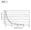
- FIG. 7 A progress of decompression in this opertion is shown in Fig. 7 with a relation between number of strokes and internal pressure.
- Fig. 8 shows hose connections of the vacuum pump of this exemplary embodiment. Like numerals have been used throughout to represent like components as in Fig. 2, and their description will be skipped.
- a gauge manifold 12 and a pressure-tight hose 11 are omitted as opposed to that shown in Fig. 2, and a pressure-tight hose 13 is connected to the service port 8b shown in Fig. 1.
- a discharge check valve 23a and a suction check valve 25a are mounted directly to a top end plate of a cylinder, and another discharge check valve 23b and anther suction check valve 25b are mounted directly to a bottom end plate of the cylinder.
- Airflow detectors 24a and 24b are attached to the discharge check valves 23a and 23b respectively.
- the above-described structure shown in Fig. 3 and 4 is employed for the discharge check valves 23a and 23b.
- the structure shown in Fig. 9 is employed for the suction check valves 25a and 25b.
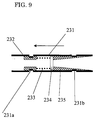
- Fig. 9 depicts a longitudinal section of the suction check valve, in which grooves are roll-formed in a copper pipe 231 at two places.
- a valve retainer seat 232 made of brass is fixed to one groove 231a, and another valve retainer seat 235 also made of brass is fixed to another groove 231b.
- a thin plate 234 made of nylon film and connected to a helical spring 233 is thrust against the valve retainer seat 235 with the spring force to block an airflow passage in an opposite direction of an arrow. Therefore, the air flows only in a direction of the arrow when the air pressure exceeds the force of spring.
- An airflow passage in the upstream side of the valve retainer seat 235 is tapered to increase the air pressure to some extent by throttling the suctioned air.
- a capacity of the cylinder is 200ml (i.e. 27mm in diameter by 350mm).
- Fig. 10 shows definitively the capacity C2 bounded from a lower surface of the piston 15 to the suction check valve 25b and the discharge check valve 23b when the piston 15 is at its lowest position.
- This exemplary embodiment reduces the capacity C2, by mounting the suction check valve 25b and the discharge check valve 23b directly to the bottom end plate of the cylinder 14.
- a ring 21 C having a gourd-shaped cross section is placed as a shaft seal in a part where the piston shaft 16 penetrates the top end plate of the cylinder 14, as shown in Fig. 11.
- the gourd-shaped ring 21 C seals the shaft doubly.
- Fig. 12 depicts an internal structure of flow detectors 24a and 24b.
- a shaft 241 is positioned in a center of a film 242 along its orthogonal direction.
- An arrow indicates a direction of airflow from the cylinder to a discharge port.
- the film 242 moves when air from the check valve strikes upon it.
- An operator is able to see if there still exists a certain amount of air to be discharged by observing a movement of the film 242. He then stops operation of the vacuum pump when he so judges that there hardly is any air remaining to be discharged from the discharge port. In this exemplary embodiment, it is judged that there hardly exists any air to be discharged from the discharge port, when an internal pressure of the cylinder reaches 20torr or lower.
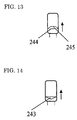
- a silicone film 244 is arranged in a manner to confront the direction of airflow.
- the silicone film deforms into a convexed dome-like shape as shown by a numeral 245 when there is a flow of air.
- the operator is able to see if there is a certain amount of air to be discharged according to a shape of the silicone film.
- a float 243 having a rather flat triangular pyramid shape moves by the air flowing toward it from the check valve. The operator is able to see if there is a certain amount of air to be discharged by observing a movement of the float 243.
- the efficiency value of C1/C2 is important for the vacuum pump of this invention.
- An internal pressure of 30torr or lower in the cylinder can be attained when the formula of C1/C2 ⁇ 40 is satisfied in designing.
- the formula of C1/C2 ⁇ 40 is necessary in order to assure reliability of the refrigeration cycle for an extended period of time. If the value of C1/C2 is too large, it gives rise to a problem in workability, although it makes no difficulty in gaining a degree of vacuum.
- the vacuum pump of this invention is provided with a double seal for the piston shaft, using double O-ring or a gourd-shaped ring made of elastomer having approximately 60 to 90 in hardness as measured by a spring type instrument of A-type (Japanese Industrial Standard K6301), such as HNBR (Hydrogenated nitrile-butadiene rubber), CR (Chloroprene rubber), EPDM (Ethylene propylene-diene), NBR (Nitrile-butadiene rubber), and the like.
- An outside seal of the double seal fulfills the function of removing dust that adheres to the piston shaft when the piston shaft travels outside of the cylinder.
- the double seal can maintain air-tightness with any one of the seals even if air leakage occurs through another of the seals due to an abrupt movement of the piston shaft.
- a light-weight small metallic ball movably placed in a pipe may be used to construct a closing valve structure.
- resins as nylon, fluorine series resins like PFA (Perfluoro-alkoxy-fluoro plastics) and PVDF (Polyvinylidene fluoride), PPS (Polyphenylene sulfide), and the like may also be suitable to use for the check valves.
- the check valve for the inlet port is capable of blocking airflow with a difference in pressure as small as 10torr or less, and more desirably 1torr or less, since there decreases the difference between an internal pressure of the indoor unit and the connecting tubes, and an internal pressure of the cylinder, as the piston is continued to operate.
- the piston of the vacuum pump is adaptable for operation with a foot treadle, although the piston in the above exemplary embodiments is illustrated as being operable with hand.
- this provides an advantageous effect to reduction of the environmental burden during installation of the air conditioner, because the satisfactory level of vacuum is attainable with human power using the handlebar or the treadle, as opposed to the conventional motor-driven pump.
Landscapes
- Engineering & Computer Science (AREA)
- Mechanical Engineering (AREA)
- General Engineering & Computer Science (AREA)
- Compressors, Vaccum Pumps And Other Relevant Systems (AREA)
- Compressor (AREA)
Abstract
Description
Claims (13)
- A vacuum pump comprising:wherein an upper chamber and a lower chamber in said cylinder alternately suction air from a subject of suctioning through said suction check valve on the top end plate and said suction check valve on the bottom end plate, and discharge the suctioned air to the outer space through said discharge check valve on the top end plate and said discharge check valve on the bottom end plate, in synchronization with the reciprocatory movement of said piston.a cylinder provided with a top end plate covering a top end of said cylinder and a bottom end plate covering a bottom end of said cylinder;a piston for reciprocating between a top position and a bottom position in said cylinder, said piston having an upper surface and a lower surface, and dividing an interior of said cylinder into two chambers;a piston shaft connected to the upper surface of said piston, said piston shaft protruding outwardly from said cylinder through the top end plate of said cylinder;a suction check valve disposed to the top end plate of said cylinder, for allowing suction air to said cylinder pass through, but not allowing discharge air from said cylinder pass though;a discharge check valve disposed to the top end plate of said cylinder, for allowing discharge air from said cylinder pass though, but not allowing suction air to said cylinder pass through;a suction check valve disposed to the bottom end plate of said cylinder, for allowing suction air to said cylinder pass through, but not allowing discharge air from said cylinder pass though; anda discharge check valve disposed to the bottom end plate of said cylinder, for allowing discharge air from said cylinder pass though, but not allowing suction air to said cylinder pass through,
- The vacuum pump as set forth in claim 1 having a structure satisfying a formula, which is C1/C2 ≥ 40, whereC1 represents a capacity bounded from the lower surface of said piston to said suction check valve and said discharge check valve disposed to the bottom end plate of said cylinder when said piston is at the top position, andC2 represents a capacity bounded from the lower surface of said piston to said suction check valve and said discharge check valve disposed to the bottom end plate of said cylinder when said piston is at the bottom position.
- The vacuum pump as set forth in any of claim 1 and claim 2, wherein an airflow passage to said suction check valve disposed to the top end plate of said cylinder and another airflow passage to said suction check valve disposed to the bottom end plate of said cylinder are connected together into one airflow passage outside said cylinder.
- The vacuum pump as set forth in any one of claim 1 through claim 3 further having a handlebar attached to a top end of said piston shaft protruding outwardly from said cylinder for manual operation.
- The vacuum pump as set forth in any one of claim 1 through claim 4 further having filters, each of said filters connected detachably to a hose comprising the airflow passage to said suction check valve disposed to the top end plate of said cylinder, and another hose comprising the airflow passage to said suction check valve disposed to the bottom end plate of said cylinder.
- The vacuum pump as set forth in claim 5, wherein said filter has a transparent container.
- The vacuum pump as set forth in any one of claim 1 through claim 6 further having an airflow detector connected to at least one of said discharge check valve disposed to the top end plate of said cylinder and said discharge check valve disposed to the bottom end plate of said cylinder.
- The vacuum pump as set forth in claim 7, wherein said airflow detector is provided with a film or a movable element moved by the airflow.
- The vacuum pump as set forth in any one of claim 1 through claim 8 further comprising a shaft seal disposed to a part of the top end plate of said cylinder where said piston shaft passes through.
- The vacuum pump as set forth in claim 9, wherein said shaft seal is formed of elastomer, and seals said piston shaft at least double.
- The vacuum pump as set forth in any one of claim 1 through claim 10 wherein a minimum operable pressure difference of said suction check valve is 10torr or less.
- The vacuum pump as set forth in claim 11, wherein said suction check valve has a structure comprising a thin plate made of resin film and a spring for blocking the airflow when said thin plate is thrust against the airflow passage with said spring.
- The vacuum pump as set forth in claim 12, wherein said airflow passage is tapered in an upstream side of a point where the airflow is blocked.
Applications Claiming Priority (2)
| Application Number | Priority Date | Filing Date | Title |
|---|---|---|---|
| JP2000201887A JP3264277B2 (en) | 2000-07-04 | 2000-07-04 | Vacuum pump |
| JP2000201887 | 2000-07-04 |
Publications (3)
| Publication Number | Publication Date |
|---|---|
| EP1170505A2 true EP1170505A2 (en) | 2002-01-09 |
| EP1170505A3 EP1170505A3 (en) | 2003-08-20 |
| EP1170505B1 EP1170505B1 (en) | 2004-10-27 |
Family
ID=18699491
Family Applications (1)
| Application Number | Title | Priority Date | Filing Date |
|---|---|---|---|
| EP20010116244 Expired - Lifetime EP1170505B1 (en) | 2000-07-04 | 2001-07-04 | Vacuum Pump |
Country Status (4)
| Country | Link |
|---|---|
| EP (1) | EP1170505B1 (en) |
| JP (1) | JP3264277B2 (en) |
| CN (1) | CN2485447Y (en) |
| ES (1) | ES2231349T3 (en) |
Cited By (5)
| Publication number | Priority date | Publication date | Assignee | Title |
|---|---|---|---|---|
| EP1336758A3 (en) * | 2002-02-15 | 2004-02-04 | Matsushita Electric Industrial Co., Ltd. | Vacuum pump and installation method for air conditioner |
| CN101922437A (en) * | 2010-08-05 | 2010-12-22 | 友达光电股份有限公司 | Vacuum equipment |
| DE102014001234A1 (en) * | 2014-01-29 | 2015-07-30 | Festo Ag & Co. Kg | Muscle powered air pump |
| CN111633670A (en) * | 2020-04-22 | 2020-09-08 | 长春职业技术学院 | Sorting manipulator for linear output of formed mechanical parts |
| CN114682437A (en) * | 2020-12-31 | 2022-07-01 | 苏州卓兆点胶股份有限公司 | Multifunctional vacuum dispensing device |
Families Citing this family (4)
| Publication number | Priority date | Publication date | Assignee | Title |
|---|---|---|---|---|
| CN102102662B (en) * | 2009-12-17 | 2014-03-19 | 国家电网公司 | Vacuum pump with anti-back suction function |
| CN105222426B (en) * | 2015-09-08 | 2017-11-28 | 珠海格力电器股份有限公司 | Vacuumizing device and method and air conditioning equipment |
| CN107795454B (en) * | 2017-09-12 | 2018-11-23 | 广州嘉诺工业技术有限公司 | A kind of wind-driven generator liquid spring vacuumizes pressurizer |
| CN112944215A (en) * | 2021-01-22 | 2021-06-11 | 浙江临安曙光印务有限公司 | Centralized gas supply system |
Family Cites Families (4)
| Publication number | Priority date | Publication date | Assignee | Title |
|---|---|---|---|---|
| DE3020534A1 (en) * | 1980-05-30 | 1981-12-03 | Willi 2906 Wardenburg Backenköhler | HOUSEHOLD EVACUATION DEVICE |
| DE4304786A1 (en) * | 1993-02-17 | 1994-08-18 | Zeolith Tech | Manually operated vacuum pump |
| US5788463A (en) * | 1995-12-22 | 1998-08-04 | Chan; Kwan-Ho | Manual vacuum producing system having pressure indicator |
| JP3257545B2 (en) | 1999-10-29 | 2002-02-18 | 松下電器産業株式会社 | Construction method of air conditioner |
-
2000
- 2000-07-04 JP JP2000201887A patent/JP3264277B2/en not_active Expired - Fee Related
-
2001
- 2001-07-04 EP EP20010116244 patent/EP1170505B1/en not_active Expired - Lifetime
- 2001-07-04 CN CN01230234U patent/CN2485447Y/en not_active Expired - Fee Related
- 2001-07-04 ES ES01116244T patent/ES2231349T3/en not_active Expired - Lifetime
Cited By (7)
| Publication number | Priority date | Publication date | Assignee | Title |
|---|---|---|---|---|
| EP1336758A3 (en) * | 2002-02-15 | 2004-02-04 | Matsushita Electric Industrial Co., Ltd. | Vacuum pump and installation method for air conditioner |
| CN101922437A (en) * | 2010-08-05 | 2010-12-22 | 友达光电股份有限公司 | Vacuum equipment |
| CN101922437B (en) * | 2010-08-05 | 2012-05-23 | 友达光电股份有限公司 | vacuum equipment |
| DE102014001234A1 (en) * | 2014-01-29 | 2015-07-30 | Festo Ag & Co. Kg | Muscle powered air pump |
| DE102014001234B4 (en) | 2014-01-29 | 2021-07-22 | Festo Se & Co. Kg | Muscle-powered air pump |
| CN111633670A (en) * | 2020-04-22 | 2020-09-08 | 长春职业技术学院 | Sorting manipulator for linear output of formed mechanical parts |
| CN114682437A (en) * | 2020-12-31 | 2022-07-01 | 苏州卓兆点胶股份有限公司 | Multifunctional vacuum dispensing device |
Also Published As
| Publication number | Publication date |
|---|---|
| EP1170505B1 (en) | 2004-10-27 |
| EP1170505A3 (en) | 2003-08-20 |
| CN2485447Y (en) | 2002-04-10 |
| JP2002021723A (en) | 2002-01-23 |
| ES2231349T3 (en) | 2005-05-16 |
| JP3264277B2 (en) | 2002-03-11 |
Similar Documents
| Publication | Publication Date | Title |
|---|---|---|
| EP0625639B1 (en) | Pump | |
| EP1170505B1 (en) | Vacuum Pump | |
| JP7148383B2 (en) | electric gas booster | |
| CN1240018A (en) | Valve-in-valve body, vent port and method | |
| TWI519712B (en) | Fluid pumps, methods of manufacturing fluid pumps, and methods of pumping fluid | |
| US20070092385A1 (en) | Pump and valve actuator system and method | |
| WO2014182472A1 (en) | Pneumatic reciprocating fluid pump with improved check valve assembly, and related methods | |
| CN104728079A (en) | Compressor and discharging muffler thereof | |
| US9856865B2 (en) | Pneumatic reciprocating fluid pump with reinforced shaft | |
| US10145372B2 (en) | Variable capacity reciprocating compressor | |
| CN1532439A (en) | Dual body service valve | |
| CN1646812A (en) | Pressure equalization system and method | |
| CN106894969A (en) | For the cylinder head assembly of reciprocating compressor | |
| CN1489682A (en) | Refrigeration Manifold | |
| JP2009162305A (en) | Flexible hose | |
| JP3257545B2 (en) | Construction method of air conditioner | |
| JP3753078B2 (en) | How to install an air conditioner | |
| JP3285034B1 (en) | Vacuum pump | |
| CN119508538B (en) | A two-in-one quick connector with liquid extraction and air intake functions | |
| CN117006013A (en) | A four-cylinder symmetrical hydrogen compression cylinder | |
| CN2763671Y (en) | Stop valve for air conditioner | |
| JP2010014165A (en) | Double pipe | |
| JP6823864B2 (en) | Six-way switching valve | |
| JP2003314447A (en) | Construction method of vacuum pump and air conditioner using it | |
| CN106286900A (en) | Straight barrel type four-way change-over valve sealing device for air conditioning for automobiles |
Legal Events
| Date | Code | Title | Description |
|---|---|---|---|
| PUAI | Public reference made under article 153(3) epc to a published international application that has entered the european phase |
Free format text: ORIGINAL CODE: 0009012 |
|
| AK | Designated contracting states |
Kind code of ref document: A2 Designated state(s): AT BE CH CY DE DK ES FI FR GB GR IE IT LI LU MC NL PT SE TR |
|
| AX | Request for extension of the european patent |
Free format text: AL;LT;LV;MK;RO;SI |
|
| PUAL | Search report despatched |
Free format text: ORIGINAL CODE: 0009013 |
|
| AK | Designated contracting states |
Designated state(s): AT BE CH CY DE DK ES FI FR GB GR IE IT LI LU MC NL PT SE TR |
|
| AX | Request for extension of the european patent |
Extension state: AL LT LV MK RO SI |
|
| 17P | Request for examination filed |
Effective date: 20030903 |
|
| 17Q | First examination report despatched |
Effective date: 20031007 |
|
| GRAP | Despatch of communication of intention to grant a patent |
Free format text: ORIGINAL CODE: EPIDOSNIGR1 |
|
| AKX | Designation fees paid |
Designated state(s): ES GR IT |
|
| REG | Reference to a national code |
Ref country code: DE Ref legal event code: 8566 |
|
| GRAS | Grant fee paid |
Free format text: ORIGINAL CODE: EPIDOSNIGR3 |
|
| GRAA | (expected) grant |
Free format text: ORIGINAL CODE: 0009210 |
|
| AK | Designated contracting states |
Kind code of ref document: B1 Designated state(s): ES GR IT |
|
| REG | Reference to a national code |
Ref country code: IE Ref legal event code: FG4D |
|
| REG | Reference to a national code |
Ref country code: GR Ref legal event code: EP Ref document number: 20040404323 Country of ref document: GR |
|
| REG | Reference to a national code |
Ref country code: ES Ref legal event code: FG2A Ref document number: 2231349 Country of ref document: ES Kind code of ref document: T3 |
|
| PLBE | No opposition filed within time limit |
Free format text: ORIGINAL CODE: 0009261 |
|
| STAA | Information on the status of an ep patent application or granted ep patent |
Free format text: STATUS: NO OPPOSITION FILED WITHIN TIME LIMIT |
|
| 26N | No opposition filed |
Effective date: 20050728 |
|
| PGFP | Annual fee paid to national office [announced via postgrant information from national office to epo] |
Ref country code: GR Payment date: 20060620 Year of fee payment: 6 |
|
| PGFP | Annual fee paid to national office [announced via postgrant information from national office to epo] |
Ref country code: ES Payment date: 20060724 Year of fee payment: 6 |
|
| PGFP | Annual fee paid to national office [announced via postgrant information from national office to epo] |
Ref country code: IT Payment date: 20060731 Year of fee payment: 6 |
|
| REG | Reference to a national code |
Ref country code: ES Ref legal event code: FD2A Effective date: 20070705 |
|
| PG25 | Lapsed in a contracting state [announced via postgrant information from national office to epo] |
Ref country code: GR Free format text: LAPSE BECAUSE OF NON-PAYMENT OF DUE FEES Effective date: 20080206 Ref country code: ES Free format text: LAPSE BECAUSE OF NON-PAYMENT OF DUE FEES Effective date: 20070705 |
|
| PG25 | Lapsed in a contracting state [announced via postgrant information from national office to epo] |
Ref country code: IT Free format text: LAPSE BECAUSE OF NON-PAYMENT OF DUE FEES Effective date: 20070704 |