EP1170503A2 - Compressor mounting - Google Patents
Compressor mounting Download PDFInfo
- Publication number
- EP1170503A2 EP1170503A2 EP01115694A EP01115694A EP1170503A2 EP 1170503 A2 EP1170503 A2 EP 1170503A2 EP 01115694 A EP01115694 A EP 01115694A EP 01115694 A EP01115694 A EP 01115694A EP 1170503 A2 EP1170503 A2 EP 1170503A2
- Authority
- EP
- European Patent Office
- Prior art keywords
- mounting
- compressing
- compressor
- housing
- section
- Prior art date
- Legal status (The legal status is an assumption and is not a legal conclusion. Google has not performed a legal analysis and makes no representation as to the accuracy of the status listed.)
- Withdrawn
Links
- 238000003780 insertion Methods 0.000 claims abstract description 15
- 230000037431 insertion Effects 0.000 claims abstract description 15
- 238000000034 method Methods 0.000 claims abstract description 6
- 230000007246 mechanism Effects 0.000 claims description 16
- 239000000463 material Substances 0.000 claims description 9
- 229910000838 Al alloy Inorganic materials 0.000 claims description 6
- 229910000831 Steel Inorganic materials 0.000 claims description 5
- 239000010959 steel Substances 0.000 claims description 5
- 230000033001 locomotion Effects 0.000 description 6
- 238000006073 displacement reaction Methods 0.000 description 5
- 230000006835 compression Effects 0.000 description 3
- 238000007906 compression Methods 0.000 description 3
- 229910001018 Cast iron Inorganic materials 0.000 description 2
- 229910000861 Mg alloy Inorganic materials 0.000 description 2
- RTAQQCXQSZGOHL-UHFFFAOYSA-N Titanium Chemical compound [Ti] RTAQQCXQSZGOHL-UHFFFAOYSA-N 0.000 description 2
- 230000004308 accommodation Effects 0.000 description 2
- XAGFODPZIPBFFR-UHFFFAOYSA-N aluminium Chemical compound [Al] XAGFODPZIPBFFR-UHFFFAOYSA-N 0.000 description 2
- 229910052782 aluminium Inorganic materials 0.000 description 2
- 238000011835 investigation Methods 0.000 description 2
- 239000003507 refrigerant Substances 0.000 description 2
- 239000010936 titanium Substances 0.000 description 2
- 229910052719 titanium Inorganic materials 0.000 description 2
- 229910045601 alloy Inorganic materials 0.000 description 1
- 239000000956 alloy Substances 0.000 description 1
- 238000005266 casting Methods 0.000 description 1
- 230000003247 decreasing effect Effects 0.000 description 1
- 235000015250 liver sausages Nutrition 0.000 description 1
- 238000004519 manufacturing process Methods 0.000 description 1
Images


Classifications
-
- F—MECHANICAL ENGINEERING; LIGHTING; HEATING; WEAPONS; BLASTING
- F04—POSITIVE - DISPLACEMENT MACHINES FOR LIQUIDS; PUMPS FOR LIQUIDS OR ELASTIC FLUIDS
- F04B—POSITIVE-DISPLACEMENT MACHINES FOR LIQUIDS; PUMPS
- F04B27/00—Multi-cylinder pumps specially adapted for elastic fluids and characterised by number or arrangement of cylinders
- F04B27/08—Multi-cylinder pumps specially adapted for elastic fluids and characterised by number or arrangement of cylinders having cylinders coaxial with, or parallel or inclined to, main shaft axis
- F04B27/10—Multi-cylinder pumps specially adapted for elastic fluids and characterised by number or arrangement of cylinders having cylinders coaxial with, or parallel or inclined to, main shaft axis having stationary cylinders
- F04B27/1036—Component parts, details, e.g. sealings, lubrication
- F04B27/1081—Casings, housings
-
- F—MECHANICAL ENGINEERING; LIGHTING; HEATING; WEAPONS; BLASTING
- F04—POSITIVE - DISPLACEMENT MACHINES FOR LIQUIDS; PUMPS FOR LIQUIDS OR ELASTIC FLUIDS
- F04B—POSITIVE-DISPLACEMENT MACHINES FOR LIQUIDS; PUMPS
- F04B27/00—Multi-cylinder pumps specially adapted for elastic fluids and characterised by number or arrangement of cylinders
- F04B27/08—Multi-cylinder pumps specially adapted for elastic fluids and characterised by number or arrangement of cylinders having cylinders coaxial with, or parallel or inclined to, main shaft axis
- F04B27/0873—Component parts, e.g. sealings; Manufacturing or assembly thereof
- F04B27/0891—Component parts, e.g. sealings; Manufacturing or assembly thereof casings, housings
-
- F—MECHANICAL ENGINEERING; LIGHTING; HEATING; WEAPONS; BLASTING
- F04—POSITIVE - DISPLACEMENT MACHINES FOR LIQUIDS; PUMPS FOR LIQUIDS OR ELASTIC FLUIDS
- F04B—POSITIVE-DISPLACEMENT MACHINES FOR LIQUIDS; PUMPS
- F04B39/00—Component parts, details, or accessories, of pumps or pumping systems specially adapted for elastic fluids, not otherwise provided for in, or of interest apart from, groups F04B25/00 - F04B37/00
- F04B39/12—Casings; Cylinders; Cylinder heads; Fluid connections
Definitions
- the present invention relates to a compressor capable of ensuring a smooth compressing motion of a compressing mechanism by devising a mounting structure of the compressor.
- compressors there are provided various types of compressors, the structures, mechanisms and forms of which are different from each other according to the apparatus to which the compressors are applied.
- a compressor for automobile use for example, in the case of a compressor for air-conditioner use
- a compressor for air-conditioner use it is common to use a compressor in which a plurality of pistons are reciprocated in the axial direction so that refrigerant gas is compressed.
- This type compressor is compact and highly efficient. Therefore, it is suitable for a compressor to be mounted on an automobile.
- the compressor in the case of a compressor for automobile use, the compressor is mounted on an automobile in such a manner that a mounting section protruding from the compressor is fixed to a boss on the engine side with bolts.
- bolts are inserted into two cylindrical mounting sections extending in a direction perpendicular to the axial direction of a compressor, so that the compressor is fixed onto a side wall of an engine.
- bolts are inserted into four plate-shaped mounting sections having a mounting hole (mounting groove) so that a compressor is fixed to a boss on the engine side.
- cylinder housing arranged at the substantial center of the compressor, there are provided cylinders, in which pistons are reciprocated so as to suck, compress and deliver refrigerant gas, extending in the axial direction.
- the compressor when the compressor is fixed to an engine block in such a manner that a mounting section provided in a cylinder housing of the compressor is fixed to the engine block with bolts or others, the mounting section is stressed by a tightening force of the bolt, the weight of the compressor and vibration generated in the operation of the compressor. Therefore, deformation (strain, deflection and so forth) is caused according to the stress given to the mounting section. Accordingly, a cylinder housing, which is integrated with the mounting section, is also deformed. As a result, the rcundness, cylindricity and concentricity of the cylinders arranged in the cylinder housing are deteriorated.
- the above deformation of the cylinders is made as small as possible. Further, as the deformation may be also occurred in a compressing housing of the scroll type compressor or the vane type compressor, it is preferable to suppress the defamation.
- the present invention has been accomplished in view of the above circumstances. It is an object of the present invention to provide a compressor capable of ensuring a stable compressing motion by suppressing the deformation of the mounting section, compressing housing and compressing chamber, which is caused when the compressor is mounted on an automobile, by devising a structure of a mounting section provided in the compressing housing.
- the present inventors made investigations by the method of trial and error. As a result of the investigations, they were struck with an idea to reduce the deformation as much as possible. In this way, the compressor of the present invention was developed.
- a compressor of the present invention comprises: a compressing housing having a compressing chamber; a side housing arranged on one side of the compressing housing; an input shaft being rotated when it receives a drive force; a compressing mechanism arranged in the compressing chamber and drived when the input shaft is rotated; and a mounting section having an insertion hole, the mounting section being mounted on 1a body, on which the compressor is mounted, with a bolt, wherein the mounting section includes a highly rigid section, arranged in an outer circumferential section of the compressing housing, for suppressing deformation of the compressor which is caused in the process of mounting the compressor.
- the mounting section arranged in the compressing housing has a highly rigid section, even when the compressor is mounted on a body (for example, an engine), on which the compressor is mounted, with bolts, deformation (strain, deflection and so forth) of the mounting section can be suppressed.
- deformation of the compressing housing caused in the process of mounting the compressor can be suppressed and further deformation of the compressing chamber arranged inside the compressing housing can be suppressed. Accordingly, it is possible to ensure a stable smooth compressing motion of the compressing mechanism. Due to the foregoing, when the compressor of the present invention is used, it is possible to enhance the efficiency of compression and reduce the power loss.
- This mounting section may be composed of either an integrated structure or a split structure.
- the compressing housing may be cast together with a highly rigid cylindrical member in the casting process of the compressing housing.
- the more specific structure of the compressor is described as follows.
- the compressor comprises: a compressing housing having a compressing chamber; a side housing arranged on one side of the compressing housing; an input shaft being rotated when it receives a drive force; a compressing mechanism arranged in the compressing chamber and drived when the input shaft is rotated; and a mounting section having an insertion hole, the mounting section being mounted on a body, on which the compressor is mounted, with a bolt, wherein the mounting section includes at least a pair of parallel mounting pieces protruding from an outer circumferential section of the compressing housing, each mounting piece having an insertion hole into which a mounting bolt is coaxially inserted, and the mounting section also includes a bush, the rigidity of which is higher than that of the mounting pieces, inserted into between the mounting pieces.
- the deformation of the mounting piece integrated with the compressing housing can be suppressed.
- the deformation of the compressing chamber provided in the compressing housing can be suppressed, so that the compressing mechanism can be smoothly moved.
- FIG. 1 is a view showing an overall arrangement of the variable displacement swash plate type compressor C, which will be referred to as "compressor C" in this specification hereinafter, which is an embodiment of the present invention.
- a housing of the variable displacement swash plate type compressor C includes: a cylinder block 10 (compressing housing) in which a plurality of cylinders (compressing chamber) 1 and a shaft hole 2 are formed; a cup-shaped front housing 20 (side housing) arranged at the front end of the cylinder block 10, a shaft hole 21 being formed in the front housing 20; and a rear housing 30 arranged at the rear end of the cylinder block 10, the rear housing 30 holding suction valves, a valve plate, discharge valves and a retainer, not shown.
- an input shaft 12 which is arranged from the front end of the front housing 20 to the rear portion of the cylinder block 10.
- a rear end side of the input shaft 12 is supported by the radial bearing 3 arranged in the shaft hole 2 of the cylinder block 10.
- a front end side of the input shaft 12 is supported by the radial bearing 24 and the shaft seal device 23 arranged in the shaft hole 21 of the front housing 20.
- a pulley 41 which is fixed to the input shaft 12 via the boss 40 integrated with the pulley 41.
- the pulley 41 is supported by the bearing 43 arranged on the outer circumference of the front end of the front housing 20.
- a belt 44 which is wound round the crank pulley not shown on the engine side, is wound round this pulley 41, so that a drive force is received by the pulley 41 and the input shaft 12 is rotated.
- a lug plate 26 is fixed to the input shaft 12. This lug plate 26 is slidably contacted with the inner wall of the front housing 20 via the thrust bearing 25.
- the lug plate 26 is provided with a pair of arms 27 protruding backward. Each arm 27 has a guide hole 28, the inner face of which is formed cylindrical. At the rear of the lug plate 26, there is provided a swash plate 16 into which the input shaft 12 is inserted.
- the swash plate 16 has a pair of guide pins 11 protruding forward. Each guide pin 11 has a spherical guide section 29 at the forward end, and the guide section 29 is slidably engaged in the guide hole 28 of the lug plate 26.
- Oscillating rotation of the swash plate 16 is converted into reciprocating motions of the pistons (compressing mechanism) 19 provided in the cylinders 1 via the shoes 15 which form a pair in the periphery of the swash pate 16.
- the stroke of the piston 19 is changed, so that the compression (discharge) capacity is changed In this way, a compressor C is obtained.
- the swash plate 16 and shoes 15 correspond to the piston drive means described in the present invention.
- the compressor C of this embodiment is mounted on an engine block, which is a body on which the compressor C is mounted, by the second mounting sections 50, 51 having the mounting holes 50a, 51a and also by the mounting section 60.
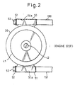
- the second mounting sections 50, 51 are composed of substantially cylindrical mounting bodies which are integrally arranged at an upper and a lower position of the outer circumference of the front housing 20 in parallel with each other in a direction perpendicular to the axial direction of the compressor C.
- the second mounting sections 50, 51 are respectively mounted on the bosses 150, 151 of the engine block by the bolts 53 via the washers 52.
- Fig. 3A is a cross-sectional view taken on line II - II in Fig. 1
- Fig. 3B is a partial cross-sectional view at the position III in Fig. 3A.
- the mounting section 60 includes: a pair of parallel plate-shaped mounting pieces 61, 62, which protrude from the cylinder block 10, having the mounting holes 61a, 62a; and a highly rigid bush 63, which is inserted between the mounting pieces 61, 62, wherein the crosssection of the bush 63 is formed into a reverse U-shape.
- the mounting section 60 is mounted on the boss 153 of the engine block via the washer 65 by the gib-headed bolt 64 (mounting bolt) which is inserted from the mounting hole 62a of the mounting piece 62 into the mounting hole 61a of the mounting piece 61 via the bush 63.
- the mounting pieces 61, 62 are made of aluminum which is the same material as that of the cylinder block 10.
- the bush 63 is made of steel, the Young's modulus of which is approximately three times as high as that of aluminum. Therefore, the entire rigidity of the mounting section 60 can be greatly enhanced. As a result, even if the gib-headed bolt 64 is used and tightened so as to fix the compressor, the deformation caused by compression and deflection of the mounting pieces 61, 62 is very small. Therefore, the deformation of the cylinder 1 is small. Accordingly, the piston can be smoothly reciprocated by sliding.
- the bush 63 instead of the bush 63, it is possible to use a cylindrical bush (sleeve) or a square-tube bush (sleeve). Further, the bush may be provided with a flange face coming into contact with the mounting piece. In the above embodiment, the bush is inserted into between the mounting pieces, however, it is possible to adopt a contrary arrangement. That is, flange faces are provided at both ends of the bush (U-shaped cross section in the axial direction), and the mounting piece may be inserted between the flange faces of the bush.
- only one mounting section 60 is provided in the cylinder block 10, however, a plurality of mounting sections 60 may be provided in the vertical direction.
- the mounting section is provided in the direction perpendicular to the axial direction of the compressor C, however, the mounting section may be provided in the direction parallel with the axial direction of the compressor c according to the shape of the boss or stay on the engine side.
- the second mounting section 50 is provided in the front housing 20 in the above embodiment, however, the second mounting section 50 may be provided in the rear housing 30.
- the highly rigid section of the mounting section and the bush may be entirely or partially highly rigid.
- highly rigid material the Young's modulus of which is high, may be used for those parts.
- the profile may be improved in such a manner that the cross-sectional area or the polar moment of inertia of area may be increased so as to increase the rigidity.
- both the material and the profile may be improved so as to increase the rigidity.
- the Young's modulus of the material of the bush is higher than that of the mounting piece.
- the bush (or sleeve) the Young's modulus of which is high, is arranged in the middle of the mounting section, the mounting section having a highly rigid section can be easily formed.
- the material of the bush may be determined according to the correlation with the material of the mounting piece.
- the bush when the mounting piece is made of aluminum alloy, the bush may be made of material, the Young's modulus of which is higher than that of aluminum alloy, such as steel, cast iron or titanium.
- the bush When the mounting piece is made of magnesium alloy, the bush may be made of material, the Young's modulus of which is higher than that of magnesium alloy, such as steel, cast iron, titanium or aluminun alloy.
- the mounting piece is made of aluminum alloy and the bush is made of steel.
- the housing of a compressor is made of aluminum alloy (including the cast housing) in many cases, and the mounting piece, which is provided integrally with the housing, is also made of aluminum alloy in many cases, when the bush, the Young's modulus of which is three times as high as that of the mounting piece, is interposed, the rigidity of the entire mounting piece is sharply increased, so that the deformation of the mounting piece, the cylinder housing and the cylinder provided in the cylinder housing can be remarkably suppressed.
- the thickness of the mounting piece is relatively decreased because the deformation of the cylinder housing can be reduced. specifically, it is preferable that the thickness of the mounting piece is reduced to be sufficiently smaller than the length of the bush or the thickness of the mounting piece is reduced to be smaller than the diameter of the insertion hole.
- the compressor of the present invention includes a second mounting section, which is located at the outer circumferential section of the side housing, having an insertion hole into which the mounting bolt is inserted.
- the second mounting section is located on the side housing in which no cylinders are arranged, the second mounting section has no relation to the deformation of the cylinder housing and the cylinder. As a result, while the piston is smoothly reciprocating in the compressor, the compressor can be more stably fixed to the engine by the mounting section of the cylinder housing and the second mounting section of the side housing.
- the second mounting section is composed of two cylindrical mounting bodies protruding in parallel with each other from two positions in the outer circumferential section of the front housing (one of the side housings) arranged on the front end side of the cylinder housing.
- the second mounting section is composed of a cylindrical mounting body, the rigidity of the second mounting section is so high that the deformation is small when it is tightened and fixed. Since two or more cylindrical mounting bodies are protruding in parallel with each other and further the mounting section is arranged in the cylinder housing, the compressor can be stably supported by three or more mounting bodies.
- the mounting section of the cylinder housing can be used as a temporary fixing means in the case of mounting the compressor on the engine.
- the temporary fixing means is arranged as described above, it becomes easy to mount the compressor on the engine.
- the arranging positions, arranging numbers, arranging directions and arranging profiles of the mounting section provided in the cylinder housing and the second mounting section provided in the side housing are determined by the correlation with a body on which the compressor is mounted. Therefore, they are not particularly restricted.
- the insertion hole of the mounting section is not limited to a hole profile which is completely closed.
- the profile of the insertion hole of the mounting section includes a U-shape, in which a portion is open, and a C-shape groove (insertion groove).
- the profile of the bush may be a cylindrical or a square-tube shape. Further, the profile of the bush may be a U-shape or a C-shaped groove.
- the bolt inserted into the insertion hole may be a common gib-headed bolt or a stud bolt which is embedded in a body on which the compressor is mounted.
- a stud bolt which is embedded in a body on which the compressor is mounted.
- the nut may be tightened with a wrench. Therefore, it is unnecessary to provide a large work space for mounting the compressor.
- the compressor of the present invention can be applied to various forms.
- the present invention can be applied to a swash plate type compressor or a wobble type compressor.
- the present invention can be applied to a double-headed type compressor or a single-headed type compressor.
- the present invention can be applied to a variable displacement type compressor or a fixed displacement type compressor.
- the present invention may be applied to a scroll type compressor or a vane type compressor. In the case, the deformation of a compressing housing and a compressing chamber accommodating a scroll compressing mechanism or a vane compressing mechanism is prevented, and therefore, it is possible to ensure a smooth motion of the compressing mechanism.
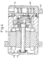
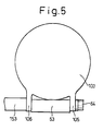
- the present invention may be applied to many kinds of motorized compressors. That is, as shown in Fig. 4, the present invention may be applied to a scroll type motorized compressor drived by a motor 102 accommodated in a side housing 101, in which a compressing housing 103 accommodates a scroll compressing mechanism 104. In this case, a highly rigid section 63 (bush) for suppressing the deformation is also provided between a pair of mounting pieces 105, 106 on the compressing housing 103, as shown in Fig. 5. Further, the present invention is not limited to a compressor for automobile use or a compressor for air-conditioner use.
- the deformation of the compressing housing caused in the process of mounting it can be suppressed. Therefore, it is possible to ensure a smooth compressing motion of a compressing mechanism.
Landscapes
- Engineering & Computer Science (AREA)
- Mechanical Engineering (AREA)
- General Engineering & Computer Science (AREA)
- Manufacturing & Machinery (AREA)
- Compressor (AREA)
- Compressors, Vaccum Pumps And Other Relevant Systems (AREA)
Abstract
The compressor of the present invention includes a
mounting section which is arranged in the outer
circumferential section of a compressing housing provided
with a compressing chamber, the mounting section having
insertion holes (61a, 62a) into which a mounting bolt
(64) is inserted, and the mounting section having a
highly rigid section (bush) (63) for suppressing the
deformation caused in the process of mounting the
compressor.
Description
- The present invention relates to a compressor capable of ensuring a smooth compressing motion of a compressing mechanism by devising a mounting structure of the compressor.
- There are provided various types of compressors, the structures, mechanisms and forms of which are different from each other according to the apparatus to which the compressors are applied. For example, in the case of a compressor for automobile use (for example, in the case of a compressor for air-conditioner use), it is common to use a compressor in which a plurality of pistons are reciprocated in the axial direction so that refrigerant gas is compressed. This type compressor is compact and highly efficient. Therefore, it is suitable for a compressor to be mounted on an automobile.
- In this connection, in the case of a compressor for automobile use, the compressor is mounted on an automobile in such a manner that a mounting section protruding from the compressor is fixed to a boss on the engine side with bolts.
- For example, according to Japanese Unexamined Utility Model Publication, No. 2-43478, bolts are inserted into two cylindrical mounting sections extending in a direction perpendicular to the axial direction of a compressor, so that the compressor is fixed onto a side wall of an engine.
- Also, according to Japanese Unexamined Utility Model Publication No. 7-14178, bolts are inserted into four plate-shaped mounting sections having a mounting hole (mounting groove) so that a compressor is fixed to a boss on the engine side.
- As can be understood from the above conventional mounting structure for mounting a compressor, in order to stably fix the compressor or in order to temporarily incorporate the compressor while the mounting property to mount the compressor is being enhanced, it is necessary to provide at least one mounting section in a housing which is arranged substantially at the center of the compressor.
- However, in the housing (cylinder housing) arranged at the substantial center of the compressor, there are provided cylinders, in which pistons are reciprocated so as to suck, compress and deliver refrigerant gas, extending in the axial direction.
- Therefore, when the compressor is fixed to an engine block in such a manner that a mounting section provided in a cylinder housing of the compressor is fixed to the engine block with bolts or others, the mounting section is stressed by a tightening force of the bolt, the weight of the compressor and vibration generated in the operation of the compressor. Therefore, deformation (strain, deflection and so forth) is caused according to the stress given to the mounting section. Accordingly, a cylinder housing, which is integrated with the mounting section, is also deformed. As a result, the rcundness, cylindricity and concentricity of the cylinders arranged in the cylinder housing are deteriorated. In order to stably reciprocate the pistons arranged in the cylinders, it is preferable that the above deformation of the cylinders is made as small as possible. Further, as the deformation may be also occurred in a compressing housing of the scroll type compressor or the vane type compressor, it is preferable to suppress the defamation.
- The present invention has been accomplished in view of the above circumstances. It is an object of the present invention to provide a compressor capable of ensuring a stable compressing motion by suppressing the deformation of the mounting section, compressing housing and compressing chamber, which is caused when the compressor is mounted on an automobile, by devising a structure of a mounting section provided in the compressing housing.
- In order to solve the above problems, the present inventors made investigations by the method of trial and error. As a result of the investigations, they were struck with an idea to reduce the deformation as much as possible. In this way, the compressor of the present invention was developed.
- A compressor of the present invention comprises: a compressing housing having a compressing chamber; a side housing arranged on one side of the compressing housing; an input shaft being rotated when it receives a drive force; a compressing mechanism arranged in the compressing chamber and drived when the input shaft is rotated; and a mounting section having an insertion hole, the mounting section being mounted on 1a body, on which the compressor is mounted, with a bolt, wherein the mounting section includes a highly rigid section, arranged in an outer circumferential section of the compressing housing, for suppressing deformation of the compressor which is caused in the process of mounting the compressor.
- Since the mounting section arranged in the compressing housing has a highly rigid section, even when the compressor is mounted on a body (for example, an engine), on which the compressor is mounted, with bolts, deformation (strain, deflection and so forth) of the mounting section can be suppressed. As a result, deformation of the compressing housing caused in the process of mounting the compressor can be suppressed and further deformation of the compressing chamber arranged inside the compressing housing can be suppressed. Accordingly, it is possible to ensure a stable smooth compressing motion of the compressing mechanism. Due to the foregoing, when the compressor of the present invention is used, it is possible to enhance the efficiency of compression and reduce the power loss.
- This mounting section may be composed of either an integrated structure or a split structure. For example, in the case where the mounting section is composed of the integrated structure, the compressing housing may be cast together with a highly rigid cylindrical member in the casting process of the compressing housing.
- In the case where the mounting section is composed of a split structure, the more specific structure of the compressor is described as follows.
- The compressor comprises: a compressing housing having a compressing chamber; a side housing arranged on one side of the compressing housing; an input shaft being rotated when it receives a drive force; a compressing mechanism arranged in the compressing chamber and drived when the input shaft is rotated; and a mounting section having an insertion hole, the mounting section being mounted on a body, on which the compressor is mounted, with a bolt, wherein the mounting section includes at least a pair of parallel mounting pieces protruding from an outer circumferential section of the compressing housing, each mounting piece having an insertion hole into which a mounting bolt is coaxially inserted, and the mounting section also includes a bush, the rigidity of which is higher than that of the mounting pieces, inserted into between the mounting pieces.
- Due to the foregoing, the deformation of the mounting piece integrated with the compressing housing can be suppressed. As a result, the deformation of the compressing chamber provided in the compressing housing can be suppressed, so that the compressing mechanism can be smoothly moved.
- The present invention may be more fully understood from the description of preferred embodiments of the invention set forth below, together with the accompanying drawings.
- In the drawings:
- Fig. 1 is an overall cross-sectional view showing a variable displacement swash plate type compressor of an embodiment of the present invention;
- Fig. 2 is a view taken in the direction of I in Fig. 1 showing a mounting state in which mounting is made by a second mounting section arranged in a front housing; and
- Figs. 3A and 3B are views showing a mounting section arranged on a cylinder block, wherein Fig. 3A is a cross-sectional view taken on line II - II in Fig. 1, and Fig. 3B is a partial cross-sectional view at position III in Fig. 3A.
- Fig. 4 is a cross-sectional view showing a scroll type motorized compressor applying the present invention.
- Fig. 5 is a view showing a mounting section arranged on a compressing housing of the scroll type motorized compressor shown in Fig. 4.
-
- Referring to an embodiment of the compressor of the present invention, the present invention will be specifically explained below.
- Fig. 1 is a view showing an overall arrangement of the variable displacement swash plate type compressor C, which will be referred to as "compressor C" in this specification hereinafter, which is an embodiment of the present invention. A housing of the variable displacement swash plate type compressor C includes: a cylinder block 10 (compressing housing) in which a plurality of cylinders (compressing chamber) 1 and a
shaft hole 2 are formed; a cup-shaped front housing 20 (side housing) arranged at the front end of thecylinder block 10, ashaft hole 21 being formed in thefront housing 20; and arear housing 30 arranged at the rear end of thecylinder block 10, therear housing 30 holding suction valves, a valve plate, discharge valves and a retainer, not shown. - At the center of a swash
plate accommodation chamber 22 which is formed by thecylinder block 10 and thefront housing 20, there is provided aninput shaft 12 which is arranged from the front end of thefront housing 20 to the rear portion of thecylinder block 10. A rear end side of theinput shaft 12 is supported by the radial bearing 3 arranged in theshaft hole 2 of thecylinder block 10. A front end side of theinput shaft 12 is supported by the radial bearing 24 and the shaft seal device 23 arranged in theshaft hole 21 of thefront housing 20. At a front end of theinput shaft 12, there is provided apulley 41 which is fixed to theinput shaft 12 via theboss 40 integrated with thepulley 41. In this connection, thepulley 41 is supported by thebearing 43 arranged on the outer circumference of the front end of thefront housing 20. Abelt 44, which is wound round the crank pulley not shown on the engine side, is wound round thispulley 41, so that a drive force is received by thepulley 41 and theinput shaft 12 is rotated. - In the swash
plate accommodation chamber 22, alug plate 26 is fixed to theinput shaft 12. Thislug plate 26 is slidably contacted with the inner wall of thefront housing 20 via the thrust bearing 25. - The
lug plate 26 is provided with a pair ofarms 27 protruding backward. Eacharm 27 has aguide hole 28, the inner face of which is formed cylindrical. At the rear of thelug plate 26, there is provided aswash plate 16 into which theinput shaft 12 is inserted. Theswash plate 16 has a pair ofguide pins 11 protruding forward. Eachguide pin 11 has aspherical guide section 29 at the forward end, and theguide section 29 is slidably engaged in theguide hole 28 of thelug plate 26. - Due to the arrangement of the
arm 27 of thelug plate 26 and theguide pin 11 of theswash plate 16, when thelug plate 26 is rotated integrally with theinput shaft 12, theswash plate 16 is rotated synchronously with thelug plate 26. However, since theguide section 29 can be moved in theguide hole 28, it is possible for theswash plate 16 to change its tilt angle according to a state of operation of the compressor. - Oscillating rotation of the
swash plate 16 is converted into reciprocating motions of the pistons (compressing mechanism) 19 provided in thecylinders 1 via theshoes 15 which form a pair in the periphery of theswash pate 16. When a tilt angle of theswash plate 16 is changed, the stroke of thepiston 19 is changed, so that the compression (discharge) capacity is changed In this way, a compressor C is obtained. In this embodiment, theswash plate 16 andshoes 15 correspond to the piston drive means described in the present invention. - In this connection, as shown in Fig. 1, the compressor C of this embodiment is mounted on an engine block, which is a body on which the compressor C is mounted, by the second mounting
sections holes section 60. - As shown in Fig. 2, the second mounting
sections front housing 20 in parallel with each other in a direction perpendicular to the axial direction of the compressor C. - The
second mounting sections bosses bolts 53 via thewashers 52. - As shown in Figs. 1, 3A and 3B, the mounting
section 60 is located at a central upper position at the rear of thecylinder block 10 in a direction perpendicular to the axial direction of the compressor C. In this connection, Fig. 3A is a cross-sectional view taken on line II - II in Fig. 1, and Fig. 3B is a partial cross-sectional view at the position III in Fig. 3A. - The mounting
section 60 includes: a pair of parallel plate-shaped mountingpieces cylinder block 10, having the mountingholes 61a, 62a; and a highlyrigid bush 63, which is inserted between the mountingpieces bush 63 is formed into a reverse U-shape. The mountingsection 60 is mounted on theboss 153 of the engine block via thewasher 65 by the gib-headed bolt 64 (mounting bolt) which is inserted from the mounting hole 62a of the mountingpiece 62 into the mountinghole 61a of the mountingpiece 61 via thebush 63. - In this case, the mounting
pieces cylinder block 10. On the other hand, thebush 63 is made of steel, the Young's modulus of which is approximately three times as high as that of aluminum. Therefore, the entire rigidity of the mountingsection 60 can be greatly enhanced. As a result, even if the gib-headedbolt 64 is used and tightened so as to fix the compressor, the deformation caused by compression and deflection of the mountingpieces cylinder 1 is small. Accordingly, the piston can be smoothly reciprocated by sliding. - In this connection, instead of the
bush 63, it is possible to use a cylindrical bush (sleeve) or a square-tube bush (sleeve). Further, the bush may be provided with a flange face coming into contact with the mounting piece. In the above embodiment, the bush is inserted into between the mounting pieces, however, it is possible to adopt a contrary arrangement. That is, flange faces are provided at both ends of the bush (U-shaped cross section in the axial direction), and the mounting piece may be inserted between the flange faces of the bush. - In the above embodiment, only one mounting
section 60 is provided in thecylinder block 10, however, a plurality of mountingsections 60 may be provided in the vertical direction. - In the above embodiment, the mounting section is provided in the direction perpendicular to the axial direction of the compressor C, however, the mounting section may be provided in the direction parallel with the axial direction of the compressor c according to the shape of the boss or stay on the engine side.
- The
second mounting section 50 is provided in thefront housing 20 in the above embodiment, however, thesecond mounting section 50 may be provided in therear housing 30. - Referring to embodiments of the compressor of the present invention, more detailed explanations will be made of the present invention.
- The highly rigid section of the mounting section and the bush may be entirely or partially highly rigid. In this case, highly rigid material, the Young's modulus of which is high, may be used for those parts. Alternatively, the profile may be improved in such a manner that the cross-sectional area or the polar moment of inertia of area may be increased so as to increase the rigidity. Alternatively, both the material and the profile may be improved so as to increase the rigidity.
- For example, it is preferable that the Young's modulus of the material of the bush is higher than that of the mounting piece. When the bush (or sleeve), the Young's modulus of which is high, is arranged in the middle of the mounting section, the mounting section having a highly rigid section can be easily formed.
- In this case, the material of the bush may be determined according to the correlation with the material of the mounting piece. For example, when the mounting piece is made of aluminum alloy, the bush may be made of material, the Young's modulus of which is higher than that of aluminum alloy, such as steel, cast iron or titanium. When the mounting piece is made of magnesium alloy, the bush may be made of material, the Young's modulus of which is higher than that of magnesium alloy, such as steel, cast iron, titanium or aluminun alloy.
- Especially, it is more preferable that the mounting piece is made of aluminum alloy and the bush is made of steel.
- From the viewpoint of reducing the weight and the manufacturing cost, the housing of a compressor is made of aluminum alloy (including the cast housing) in many cases, and the mounting piece, which is provided integrally with the housing, is also made of aluminum alloy in many cases, when the bush, the Young's modulus of which is three times as high as that of the mounting piece, is interposed, the rigidity of the entire mounting piece is sharply increased, so that the deformation of the mounting piece, the cylinder housing and the cylinder provided in the cylinder housing can be remarkably suppressed.
- In this connection, it is preferable that the thickness of the mounting piece is relatively decreased because the deformation of the cylinder housing can be reduced. specifically, it is preferable that the thickness of the mounting piece is reduced to be sufficiently smaller than the length of the bush or the thickness of the mounting piece is reduced to be smaller than the diameter of the insertion hole.
- In the case of fixing the compressor to an engine, when the mounting section is arranged in the side housing in addition to the mounting section arranged in the cylinder housing, it is possible to reduce a load given to the mounting section of the cylinder housing. Therefore, it is possible to reduce the deformation caused in the cylinder housing and the cylinder provided in the cylinder housing.
- That is, it is more preferable that the compressor of the present invention includes a second mounting section, which is located at the outer circumferential section of the side housing, having an insertion hole into which the mounting bolt is inserted.
- Since the second mounting section is located on the side housing in which no cylinders are arranged, the second mounting section has no relation to the deformation of the cylinder housing and the cylinder. As a result, while the piston is smoothly reciprocating in the compressor, the compressor can be more stably fixed to the engine by the mounting section of the cylinder housing and the second mounting section of the side housing.
- Further, it is preferable that the second mounting section is composed of two cylindrical mounting bodies protruding in parallel with each other from two positions in the outer circumferential section of the front housing (one of the side housings) arranged on the front end side of the cylinder housing.
- Since the second mounting section is composed of a cylindrical mounting body, the rigidity of the second mounting section is so high that the deformation is small when it is tightened and fixed. Since two or more cylindrical mounting bodies are protruding in parallel with each other and further the mounting section is arranged in the cylinder housing, the compressor can be stably supported by three or more mounting bodies.
- In the case where the second mounting section bears the weight of the compressor, the mounting section of the cylinder housing can be used as a temporary fixing means in the case of mounting the compressor on the engine. When the temporary fixing means is arranged as described above, it becomes easy to mount the compressor on the engine.
- The arranging positions, arranging numbers, arranging directions and arranging profiles of the mounting section provided in the cylinder housing and the second mounting section provided in the side housing are determined by the correlation with a body on which the compressor is mounted. Therefore, they are not particularly restricted.
- The insertion hole of the mounting section is not limited to a hole profile which is completely closed. The profile of the insertion hole of the mounting section includes a U-shape, in which a portion is open, and a C-shape groove (insertion groove). The profile of the bush may be a cylindrical or a square-tube shape. Further, the profile of the bush may be a U-shape or a C-shaped groove.
- The bolt inserted into the insertion hole may be a common gib-headed bolt or a stud bolt which is embedded in a body on which the compressor is mounted. When the stud bolt is used, it becomes easy to temporarily mount the compressor. Further, when the stud bolt is used, the nut may be tightened with a wrench. Therefore, it is unnecessary to provide a large work space for mounting the compressor.
- As long as the above conditions are satisfied, the compressor of the present invention can be applied to various forms. For example, the present invention can be applied to a swash plate type compressor or a wobble type compressor. Also, the present invention can be applied to a double-headed type compressor or a single-headed type compressor. Also, the present invention can be applied to a variable displacement type compressor or a fixed displacement type compressor. Further, the present invention may be applied to a scroll type compressor or a vane type compressor. In the case, the deformation of a compressing housing and a compressing chamber accommodating a scroll compressing mechanism or a vane compressing mechanism is prevented, and therefore, it is possible to ensure a smooth motion of the compressing mechanism.
- Furthermore, the present invention may be applied to many kinds of motorized compressors. That is, as shown in Fig. 4, the present invention may be applied to a scroll type motorized compressor drived by a
motor 102 accommodated in aside housing 101, in which a compressinghousing 103 accommodates ascroll compressing mechanism 104. In this case, a highly rigid section 63 (bush) for suppressing the deformation is also provided between a pair of mountingpieces housing 103, as shown in Fig. 5. Further, the present invention is not limited to a compressor for automobile use or a compressor for air-conditioner use. - According to the compressor of the present invention, the deformation of the compressing housing caused in the process of mounting it can be suppressed. Therefore, it is possible to ensure a smooth compressing motion of a compressing mechanism.
Claims (10)
- A compressor comprising: a compressing housing having a compressing chamber; a side housing arranged on one side of the compressing housing; an input shaft being rotated when it receives a drive force; a compressing mechanism arranged in the compressing chamber and drived when the input shaft is rotated; and a mounting section having an insertion hole, the mounting section being mounted on a body, on which the compressor is mounted, with a bolt, wherein the mounting section includes a highly rigid section, arranged in an outer circumferential section of the compressing housing, for suppressing deformation of the compressor which is caused in the process of mounting the compressor.
- A compressor comprising: a compressing housing having a compressing chamber; a side housing arranged on one side of the compressing housing; an input shaft being rotated when it receives a drive force; a compressing mechanism arranged in the compressing chamber and drived when the input shaft is rotated; and a mounting section having an insertion hole, the mounting section being mounted on a body, on which the compressor is mounted, with a bolt, wherein the mounting section includes at least a pair of parallel mounting pieces protruding from an outer circumferential section of the compressing housing, each mounting piece having an insertion hole into which a mounting bolt is coaxially inserted, and the mounting section also includes a bush, the rigidity of which is higher than that of the mounting pieces, inserted into between the mounting pieces.
- A compressor according to claim 2, wherein the bush is made of a material, the Young's modulus of which is higher than that of the mounting piece.
- A compressor according to claim 3, wherein the mounting piece is made of aluminum alloy and the bush is made of steel.
- A compressor according to claim 1, further comprising a second mounting section, arranged in an outer circumferential section of the side housing, having an insertion hole into which a mounting bolt is inserted.
- A compressor according to claim 2, further comprising a second mounting section, arranged in an outer circumferential section of the side housing, having an insertion hole into which a mounting bolt is inserted.
- A compressor according to claim 5, wherein the second mounting section is composed of cylindrical mounting bodies protruding in parallel with each other from at least two positiohs in the outer circumferential section of the side housing arranged on the front end side of the compressing housing.
- A compressor according to claim 6, wherein the second mounting section is composed of cylindrical mounting bodies protruding in parallel with each other from at least two positions in the outer circumferential section of the side housing arranged on the front end side of the compressing housing.
- A compressor according to claim 1, wherein the compressing chamber is a plurality of cylinders extending in the axial direction and arranged annularly, and the compressing mechanism is a piston slidably arranged in each cylinder of the compressing housing and drived for reciprocating each piston when the input shaft is rotated.
- A compressor according to claim 2, wherein the compressing chamber is a plurality of cylinders extending in the axial direction and arranged annularly, and the compressing mechanism is a piston slidably arranged in each cylinder of the compressing housing and drived for reciprocating each piston when the input shaft is rotated.
Applications Claiming Priority (2)
| Application Number | Priority Date | Filing Date | Title |
|---|---|---|---|
| JP2000205057 | 2000-07-06 | ||
| JP2000205057 | 2000-07-06 |
Publications (1)
| Publication Number | Publication Date |
|---|---|
| EP1170503A2 true EP1170503A2 (en) | 2002-01-09 |
Family
ID=18702207
Family Applications (1)
| Application Number | Title | Priority Date | Filing Date |
|---|---|---|---|
| EP01115694A Withdrawn EP1170503A2 (en) | 2000-07-06 | 2001-07-05 | Compressor mounting |
Country Status (2)
| Country | Link |
|---|---|
| US (1) | US20020018726A1 (en) |
| EP (1) | EP1170503A2 (en) |
Cited By (1)
| Publication number | Priority date | Publication date | Assignee | Title |
|---|---|---|---|---|
| EP1605160A4 (en) * | 2003-02-21 | 2006-08-09 | Zexel Valeo Climate Contr Corp | Reciprocating compressor |
Families Citing this family (3)
| Publication number | Priority date | Publication date | Assignee | Title |
|---|---|---|---|---|
| US7818565B2 (en) * | 2002-06-10 | 2010-10-19 | Quest Software, Inc. | Systems and methods for implementing protocol enforcement rules |
| US20090037582A1 (en) * | 2007-07-31 | 2009-02-05 | Morris Robert P | Method And System For Managing Access To A Resource Over A Network Using Status Information Of A Principal |
| JP2013204446A (en) * | 2012-03-27 | 2013-10-07 | Toyota Industries Corp | Compressor |
-
2001
- 2001-07-05 US US09/899,487 patent/US20020018726A1/en not_active Abandoned
- 2001-07-05 EP EP01115694A patent/EP1170503A2/en not_active Withdrawn
Cited By (1)
| Publication number | Priority date | Publication date | Assignee | Title |
|---|---|---|---|---|
| EP1605160A4 (en) * | 2003-02-21 | 2006-08-09 | Zexel Valeo Climate Contr Corp | Reciprocating compressor |
Also Published As
| Publication number | Publication date |
|---|---|
| US20020018726A1 (en) | 2002-02-14 |
Similar Documents
| Publication | Publication Date | Title |
|---|---|---|
| EP0908623B1 (en) | Reciprocating pistons of piston-type compressor | |
| EP0550228B1 (en) | Swash plate type compressor with variable displacemnet mechanism | |
| US6565329B2 (en) | Electric type swash plate compressor | |
| EP0809025A1 (en) | Reciprocating pistons of piston-type compressor | |
| US6158968A (en) | Fluid displacement apparatus with variable displacement mechanism | |
| CA2317157C (en) | Reversible, variable displacement compressor | |
| CN100424344C (en) | horizontally opposed compressor | |
| US5556261A (en) | Piston type compressor | |
| US6030184A (en) | Housing construction for reciprocating piston type compressor | |
| KR19980070248A (en) | Variable displacement compressor | |
| US5456158A (en) | Reciprocating compressor | |
| US20040131475A1 (en) | Shaft seal, compressor having the same and method for sealing shaft | |
| US6739236B2 (en) | Piston for fluid machine and method of manufacturing the same | |
| US20020018726A1 (en) | Compressor | |
| US5782613A (en) | Piston type compressor with structure for reducing cylinder bore deformation | |
| CN1131730A (en) | Bearing arrangement in swash plate type compressor with double headed pistons | |
| US7497671B2 (en) | Hermetic compressor | |
| US20010008607A1 (en) | Swash plate type compressor | |
| US20030059316A1 (en) | Multistage type piston compressor | |
| CN110392784B (en) | Compressor installations for compressed air supply to compressed air supply equipment | |
| JP2002081382A (en) | Compressor | |
| US6378417B1 (en) | Swash plate compressor in which an opening edge of each cylinder bore has a plurality of chamferred portions | |
| EP1233180A2 (en) | Compressor housing | |
| EP1067288A2 (en) | Thrust bearing for the swash plate of a compressor | |
| EP1170504A2 (en) | Muffler for compressor |
Legal Events
| Date | Code | Title | Description |
|---|---|---|---|
| PUAI | Public reference made under article 153(3) epc to a published international application that has entered the european phase |
Free format text: ORIGINAL CODE: 0009012 |
|
| 17P | Request for examination filed |
Effective date: 20010705 |
|
| AK | Designated contracting states |
Kind code of ref document: A2 Designated state(s): AT BE CH CY DE DK ES FI FR GB GR IE IT LI LU MC NL PT SE TR |
|
| AX | Request for extension of the european patent |
Free format text: AL;LT;LV;MK;RO;SI |
|
| STAA | Information on the status of an ep patent application or granted ep patent |
Free format text: STATUS: THE APPLICATION HAS BEEN WITHDRAWN |
|
| 18W | Application withdrawn |
Effective date: 20030429 |