EP1170498A1 - Dispositif de régulation thermique de l'air d'admission d'un moteur à combustion interne de véhicule automobile - Google Patents
Dispositif de régulation thermique de l'air d'admission d'un moteur à combustion interne de véhicule automobile Download PDFInfo
- Publication number
- EP1170498A1 EP1170498A1 EP01401521A EP01401521A EP1170498A1 EP 1170498 A1 EP1170498 A1 EP 1170498A1 EP 01401521 A EP01401521 A EP 01401521A EP 01401521 A EP01401521 A EP 01401521A EP 1170498 A1 EP1170498 A1 EP 1170498A1
- Authority
- EP
- European Patent Office
- Prior art keywords
- heat transfer
- transfer liquid
- intake air
- circuit
- heat
- Prior art date
- Legal status (The legal status is an assumption and is not a legal conclusion. Google has not performed a legal analysis and makes no representation as to the accuracy of the status listed.)
- Granted
Links
Images
Classifications
-
- F—MECHANICAL ENGINEERING; LIGHTING; HEATING; WEAPONS; BLASTING
- F02—COMBUSTION ENGINES; HOT-GAS OR COMBUSTION-PRODUCT ENGINE PLANTS
- F02M—SUPPLYING COMBUSTION ENGINES IN GENERAL WITH COMBUSTIBLE MIXTURES OR CONSTITUENTS THEREOF
- F02M31/00—Apparatus for thermally treating combustion-air, fuel, or fuel-air mixture
- F02M31/02—Apparatus for thermally treating combustion-air, fuel, or fuel-air mixture for heating
- F02M31/04—Apparatus for thermally treating combustion-air, fuel, or fuel-air mixture for heating combustion-air or fuel-air mixture
-
- F—MECHANICAL ENGINEERING; LIGHTING; HEATING; WEAPONS; BLASTING
- F02—COMBUSTION ENGINES; HOT-GAS OR COMBUSTION-PRODUCT ENGINE PLANTS
- F02B—INTERNAL-COMBUSTION PISTON ENGINES; COMBUSTION ENGINES IN GENERAL
- F02B29/00—Engines characterised by provision for charging or scavenging not provided for in groups F02B25/00, F02B27/00 or F02B33/00 - F02B39/00; Details thereof
- F02B29/04—Cooling of air intake supply
- F02B29/0406—Layout of the intake air cooling or coolant circuit
- F02B29/0437—Liquid cooled heat exchangers
- F02B29/0443—Layout of the coolant or refrigerant circuit
-
- F—MECHANICAL ENGINEERING; LIGHTING; HEATING; WEAPONS; BLASTING
- F02—COMBUSTION ENGINES; HOT-GAS OR COMBUSTION-PRODUCT ENGINE PLANTS
- F02M—SUPPLYING COMBUSTION ENGINES IN GENERAL WITH COMBUSTIBLE MIXTURES OR CONSTITUENTS THEREOF
- F02M26/00—Engine-pertinent apparatus for adding exhaust gases to combustion-air, main fuel or fuel-air mixture, e.g. by exhaust gas recirculation [EGR] systems
- F02M26/13—Arrangement or layout of EGR passages, e.g. in relation to specific engine parts or for incorporation of accessories
- F02M26/22—Arrangement or layout of EGR passages, e.g. in relation to specific engine parts or for incorporation of accessories with coolers in the recirculation passage
- F02M26/23—Layout, e.g. schematics
- F02M26/28—Layout, e.g. schematics with liquid-cooled heat exchangers
-
- F—MECHANICAL ENGINEERING; LIGHTING; HEATING; WEAPONS; BLASTING
- F02—COMBUSTION ENGINES; HOT-GAS OR COMBUSTION-PRODUCT ENGINE PLANTS
- F02M—SUPPLYING COMBUSTION ENGINES IN GENERAL WITH COMBUSTIBLE MIXTURES OR CONSTITUENTS THEREOF
- F02M26/00—Engine-pertinent apparatus for adding exhaust gases to combustion-air, main fuel or fuel-air mixture, e.g. by exhaust gas recirculation [EGR] systems
- F02M26/02—EGR systems specially adapted for supercharged engines
- F02M26/04—EGR systems specially adapted for supercharged engines with a single turbocharger
-
- Y—GENERAL TAGGING OF NEW TECHNOLOGICAL DEVELOPMENTS; GENERAL TAGGING OF CROSS-SECTIONAL TECHNOLOGIES SPANNING OVER SEVERAL SECTIONS OF THE IPC; TECHNICAL SUBJECTS COVERED BY FORMER USPC CROSS-REFERENCE ART COLLECTIONS [XRACs] AND DIGESTS
- Y02—TECHNOLOGIES OR APPLICATIONS FOR MITIGATION OR ADAPTATION AGAINST CLIMATE CHANGE
- Y02T—CLIMATE CHANGE MITIGATION TECHNOLOGIES RELATED TO TRANSPORTATION
- Y02T10/00—Road transport of goods or passengers
- Y02T10/10—Internal combustion engine [ICE] based vehicles
- Y02T10/12—Improving ICE efficiencies
Definitions
- the present invention relates to a thermal air regulation device intake of an internal combustion engine of a motor vehicle.
- a heat exchanger is generally used thermal intake air / air outside the vehicle.
- the intake air / coolant heat exchanger is generally used to heat this intake air.
- the air heat exchanger intake / heat transfer liquid is connected to a conventional cooling circuit of the engine, the heat transfer liquid generally comprising a mixture of water and antifreeze.
- US-4,096,697 describes a device for thermal regulation of the intake air an internal combustion engine of a motor vehicle, of the type comprising a intake air / heat transfer liquid heat exchanger connected to a first circuit coolant liquid called cold, intended to cool the intake air, and a second circuit of so-called hot heat transfer liquid, intended to heat the intake air, via means for distributing cold and hot heat transfer liquids in the exchanger thermal intake air / heat transfer liquid.
- the invention aims to simplify a thermal regulation installation intake air from an engine as well as optimizing the operation of such installation, in particular in the case of an engine emitting exhaust gases in part recirculated with the intake air.
- the subject of the invention is a device for thermal regulation of the intake air of an internal combustion engine of a motor vehicle, of the type described in US-4,096,697, characterized in that the engine emits partially recirculated exhaust gases and in that the device further comprises a recirculated exhaust gas / heat transfer liquid heat exchanger connected as a bypass to the intake air / heat transfer liquid heat exchanger.
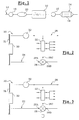
- FIG. 1 shows an internal combustion engine 10 of motor vehicle, for example of the Diesel type, connected to upstream means forming a circuit 12 for admitting air into the motor 10 and to downstream means forming a line exhaust 14.
- the engine 10 is supercharged by means of a turbo-compressor assembly provided, on the one hand, with a turbine 16 driven by exhaust gases from the engine 10, arranged downstream of the engine 10 in the exhaust line 14, and on the other hand, of a intake air compressor 18 arranged upstream of the engine 10 in the circuit 12 air intake.
- the turbine 16 and the compressor 18 are coupled in rotation to each other in a manner known per se.
- the exhaust line is fitted with a conventional particle filter 19.
- the temperature of the intake air leaving compressor 18 is regulated by means of a thermal regulation device 20 according to the invention including four modes of embodiment are shown in Figures 2 to 5. Note that in these figures the analogous elements are designated by identical references.
- FIG. 2 shows a device 20 for thermal regulation of the intake air according to a first embodiment not claimed.
- the device 20 comprises a conventional heat exchanger 22 air / coolant intended to regulate the temperature of the intake air at its output of compressor 18.
- This exchanger 22 is connected to a first circuit 24 of so-called cold coolant, intended to cool the intake air, and a second circuit 26 of so-called hot heat transfer liquid, intended to heat the intake air, via means for distributing cold and hot heat transfer liquids in exchanger 22.
- the intake air is led through the heat exchanger 22 air intake / heat transfer liquid at a pressure higher than atmospheric pressure by the compressor 18.
- the flow of intake air passing through this exchanger 22 is shown in Figure 2 by arrows oriented from left to right.
- the distribution means include a three-way distribution valve conventional 28, all or nothing type, comprising a first liquid inlet channel coolant 28A connected to the first circuit 24 of coolant, a second heat transfer liquid inlet channel 28B connected to the second liquid circuit 26 heat transfer medium and a third heat transfer liquid outlet channel 28C connected to a entry of heat transfer liquid into the heat exchanger 22 intake air / liquid coolant.
- a three-way distribution valve conventional 28, all or nothing type comprising a first liquid inlet channel coolant 28A connected to the first circuit 24 of coolant, a second heat transfer liquid inlet channel 28B connected to the second liquid circuit 26 heat transfer medium and a third heat transfer liquid outlet channel 28C connected to a entry of heat transfer liquid into the heat exchanger 22 intake air / liquid coolant.
- the heat transfer liquid circulating in each of the first 24 and second 26 circuits is of the conventional type and includes, for example, a mixture of water and antifreeze.
- the first circuit 24 of cool coolant comprises an exchanger conventional thermal 30 air outside the vehicle / cool coolant, called exchanger low temperature, preferably carried by a front face 31 of the motor vehicle.
- the cold coolant is circulated in the first circuit 24 by a conventional electric pump 32.
- the second circuit 26 of hot heat transfer liquid is connected by example to a conventional engine cooling circuit 10, not shown in the FIGS.
- this second circuit 26 can be connected to an exchanger thermal forming a hot source of a conventional heat pump.
- the operation of the thermal regulation device 20 is very simple.
- valve distribution 28 is adjusted so as to connect the heat exchanger 22 air intake / heat transfer liquid to the first circuit 24 of cold heat transfer liquid.
- the flow of cold heat transfer liquid passing through the low temperature exchanger 30 is regulated by the pump 32.
- the heat transfer liquid circulating in the exchanger 22 cools the intake air by giving him frigories.
- the distribution valve 28 is adjusted so as to connect the exchanger thermal 22 intake air / heat transfer liquid to the second liquid circuit 26 hot coolant.
- the heat transfer liquid circulating in the exchanger 22 heats the air intake by giving her calories.
- FIG. 3 shows a device 20 for thermal regulation of the intake air according to a second unclaimed embodiment which differs from the first mode by the fact that the three-way valve 28 is in this case of the type proportional.
- This three-way valve 28 can be adjusted so as to connect the exchanger thermal 22 intake air / heat transfer liquid to the first 24 and second 26 heat transfer liquid at a time.
- the temperature can be adjusted relatively precisely temperature of the heat transfer liquid passing through the exchanger 22 and therefore the temperature of intake air.
- exhaust gases are recirculation with the intake air using appropriate conventional means.
- These exhaust gases are commonly called recirculated exhaust gases EGR (Exhaust Gas Recycling).
- EGR Exhaust Gas Recycling
- the device 20 for thermal regulation of the intake air allows also to regulate the temperature of the recirculated exhaust gases for the purpose in particular to lower the temperature of these gases before being mixed with air intake and returned to engine 10.
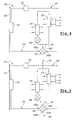
- a heat exchanger 34 recirculated exhaust gases / liquid coolant is connected bypass to the heat exchanger 22 intake air / liquid coolant.
- the recirculated exhaust gas flow passing through the heat exchanger 34 is shown in Figures 4 and 5 by arrows oriented from left to right.
- the device 20 comprises a three-way distribution valve 28, for example of the type all or nothing (similar to the valve shown in Figure 2) or of the type proportional.
- the third channel 28C of the distribution valve is connected to both the heat transfer fluid inlet in the heat exchanger 22 intake air / coolant and to a liquid inlet coolant in the heat exchanger 34 recirculated exhaust gas / liquid coolant, via a conduit 36 common to the first 24 and second 26 liquid circuits coolant.
- a valve 38 for adjusting the flow rate of heat transfer liquid in the heat exchanger 34 recirculated exhaust gases / coolant connects the common conduit 36 at the inlet of this heat exchanger 34.
- the regulating valve 38 is of the conventional type, for example of the all or nothing type or of the proportional type.
- the control valve 38 is open and the distribution valve 28 is adjusted so as to connect the heat exchanger 22 air intake / heat transfer liquid to the first circuit 24 of cold heat transfer liquid such as described for the first embodiment of the invention.
- the distribution of the heat transfer liquid flows in each of the exchangers 22, 34 can be adjusted by adjusting the valve 38.
- control valve 38 is closed and the distribution valve 28 is adjusted so as to connect the heat exchanger 22 air intake / heat transfer liquid to the second circuit 26 of hot heat transfer liquid as described for the first embodiment of the invention.
- the heat exchanger 22 intake air / coolant of the regulating device thermal 20 is connected to a third circuit 40 of coolant liquid said to be very cold, colder than the heat transfer liquid of the first circuit 24.
- This third circuit 40 is by example thermally coupled with a cold source of a heat pump of the vehicle intended in particular for air conditioning the passenger compartment of this vehicle, this cold source yielding frigories to very cold coolant.
- the heat transfer liquid circulating in the third circuit 40 is preferably a mixture of water and antifreeze, like the heat transfer liquid of the first 24 and second 26 circuits.
- valve distribution 28 is of the four-lane type and comprises, in addition to the three lanes 28A to 28C described in connection with the previous embodiments, a fourth input channel of heat transfer liquid 28D connected to the third heat transfer liquid circuit 40.
- the heat exchanger 22 intake air / heat transfer liquid is supplied with very cold heat transfer liquid, in particular to optimize the operation of the engine 10, more particularly when this motor 10 provides a high torque, for example when that the vehicle climbs a hill.
- the third circuit 40 could contain a so-called heat transfer liquid very hot, hotter than the heat transfer liquid of the second circuit 26.
- This third circuit 40 could in this case be thermally coupled with a hot source of a vehicle heat pump.
- the third circuit 40 of very hot heat transfer liquid could be used to quickly heat the intake air, particularly for regeneration of the particulate filter.
- the heat exchanger 22 intake air / heat transfer liquid used in cooling mode is more efficient than the air / air heat exchanger used in the state of the art for cooling the intake air.
- the heat exchanger 34 recirculated exhaust gases / liquid coolant can be easily integrated into the thermal regulation installation. More in particular, the heat exchanger 22 intake air / heat transfer liquid and the heat exchanger 34 recirculated exhaust gases / heat transfer liquid can be arranged in the same module, this module can be integrated into a set engine or separate from this engine assembly.
Landscapes
- Engineering & Computer Science (AREA)
- Chemical & Material Sciences (AREA)
- Combustion & Propulsion (AREA)
- Mechanical Engineering (AREA)
- General Engineering & Computer Science (AREA)
- Physics & Mathematics (AREA)
- Thermal Sciences (AREA)
- Exhaust-Gas Circulating Devices (AREA)
- Air-Conditioning For Vehicles (AREA)
Abstract
Description
- le premier circuit de liquide caloporteur froid comprend un échangeur thermique air/liquide caloporteur froid, dit échangeur basse température, porté de préférence par une face avant du véhicule automobile ;
- le liquide caloporteur froid est mis en circulation dans le premier circuit par une pompe ;
- le deuxième circuit de liquide caloporteur chaud est raccordé à un circuit de refroidissement du moteur à combustion interne ;
- le deuxième circuit de liquide caloporteur chaud est raccordé à un échangeur thermique formant une source chaude de pompe à chaleur ;
- l'air d'admission est entraíné, à une pression supérieure à la pression atmosphérique, à travers l'échangeur thermique air d'admission/liquide caloporteur par un ensemble turbo-compresseur muni d'une turbine entraínée par des gaz d'échappement du moteur à combustion interne ;
- l'échangeur thermique air d'admission/liquide caloporteur est raccordé à un troisième circuit de liquide caloporteur dit très froid, plus froid que le liquide caloporteur du premier circuit ;
- l'échangeur thermique air d'admission/liquide caloporteur est raccordé à un troisième circuit de liquide caloporteur dit très chaud, plus chaud que le liquide caloporteur du deuxième circuit ;
- les moyens de répartition comprennent une vanne de répartition, à au moins trois voies, de type tout ou rien, comprenant une première voie d'entrée de liquide caloporteur raccordée au premier circuit de liquide caloporteur, une deuxième voie d'entrée de liquide caloporteur raccordée au deuxième circuit de liquide caloporteur et une troisième voie de sortie de liquide caloporteur raccordée à une entrée de liquide caloporteur dans l'échangeur thermique air d'admission/liquide caloporteur ;
- les moyens de répartition comprennent une vanne de répartition, à au moins trois voies, de type proportionnel, comprenant une première voie d'entrée de liquide caloporteur raccordée au premier circuit de liquide caloporteur, une deuxième voie d'entrée de liquide caloporteur raccordée au deuxième circuit de liquide caloporteur et une troisième voie de sortie de liquide caloporteur raccordée à une entrée de liquide caloporteur dans l'échangeur thermique air d'admission/liquide caloporteur ;
- la vanne de répartition comprend une quatrième voie d'entrée de liquide caloporteur raccordée au troisième circuit de liquide caloporteur ;
- la troisième voie de la vanne de répartition est raccordée à la fois à l'entrée de liquide caloporteur dans l'échangeur thermique air d'admission/liquide caloporteur et à une entrée de liquide caloporteur dans l'échangeur thermique gaz d'échappement recirculés/liquide caloporteur, par un conduit commun aux premier et deuxième circuits de liquide caloporteur ;
- les moyens de répartition comprennent une vanne de réglage du débit de liquide caloporteur dans l'échangeur thermique gaz d'échappement recirculés/liquide caloporteur reliant le conduit commun et l'entrée de cet échangeur thermique gaz d'échappement recirculés/liquide caloporteur ;
- le moteur à combustion interne, de préférence de type Diesel, est raccordé à une ligne d'échappement munie d'un filtre à particules ;
- le liquide caloporteur est un mélange d'eau et d'antigel.
- la figure 1 est vue schématique d'un moteur à combustion interne raccordé à des moyens amont formant circuit d'admission d'air et à des moyens aval formant ligne d'échappement ;
- les figures 2 et 3 sont des vues schématiques de dispositifs de régulation thermique de l'air d'admission du moteur selon des premier et deuxième modes de réalisation non revendiqués ;
- les figures 4 et 5 sont des vues schématiques de dispositifs de régulation thermique de l'air d'admission du moteur selon des troisième et quatrième mode de réalisation de l'invention revendiqués.
Claims (15)
- Dispositif de régulation thermique de l'air d'admission d'un moteur à combustion interne (10) de véhicule automobile, du type comprenant un échangeur thermique (22) air d'admission/liquide caloporteur raccordé à un premier circuit (24) de liquide caloporteur dit froid, destiné à refroidir l'air d'admission, et un deuxième circuit (26) de liquide caloporteur dit chaud, destiné à réchauffer l'air d'admission, par l'intermédiaire de moyens (28 ; 38) de répartition des liquides caloporteurs froid et chaud dans l'échangeur thermique (22) air d'admission/liquide caloporteur, caractérisé en ce que le moteur émet des gaz d'échappement en partie recirculés et en ce que le dispositif comprend de plus un échangeur thermique (34) gaz d'échappement recirculés/liquide caloporteur raccordé en dérivation à l'échangeur thermique (22) air d'admission/liquide caloporteur.
- Dispositif selon la revendication 1, caractérisé en ce que le premier circuit (24) de liquide caloporteur froid comprend un échangeur thermique (30) air/liquide caloporteur froid, dit échangeur basse température, porté de préférence par une face avant (31) du véhicule automobile.
- Dispositif selon la revendication 1 ou 2, caractérisé en ce que le liquide caloporteur froid est mis en circulation dans le premier circuit (24) par une pompe (32).
- Dispositif selon l'une quelconque des revendications 1 à 3, caractérisé en ce que le deuxième circuit de liquide caloporteur chaud (26) est raccordé à un circuit de refroidissement du moteur à combustion interne.
- Dispositif selon l'une quelconque des revendications 1 à 3, caractérisé en ce que le deuxième circuit de liquide caloporteur chaud (26) est raccordé à un échangeur thermique formant une source chaude de pompe à chaleur.
- Dispositif selon l'une quelconque des revendications 1 à 4, caractérisé en ce que l'air d'admission est entraíné, à une pression supérieure à la pression atmosphérique, à travers l'échangeur thermique (22) air d'admission/liquide caloporteur par un ensemble turbo-compresseur muni d'une turbine (16) entraínée par des gaz d'échappement du moteur à combustion interne (10).
- Dispositif selon l'une quelconque des revendications 1 à 6, caractérisé en ce que l'échangeur thermique (22) air d'admission/liquide caloporteur est raccordé à un troisième circuit (40) de liquide caloporteur dit très froid, plus froid que le liquide caloporteur du premier circuit (24).
- Dispositif selon l'une quelconque des revendications 1 à 6, caractérisé en ce que l'échangeur thermique (22) air d'admission/liquide caloporteur est raccordé à un troisième circuit (40) de liquide caloporteur dit très chaud, plus chaud que le liquide caloporteur du deuxième circuit (26).
- Dispositif selon l'une quelconque des revendications 1 à 8, caractérisé en ce que les moyens de répartition comprennent une vanne de répartition (28), à au moins trois voies, de type tout ou rien, comprenant une première voie (28A) d'entrée de liquide caloporteur raccordée au premier circuit (24) de liquide caloporteur, une deuxième voie (28B) d'entrée de liquide caloporteur raccordée au deuxième circuit (26) de liquide caloporteur et une troisième voie (28C) de sortie de liquide caloporteur raccordée à une entrée de liquide caloporteur dans l'échangeur thermique (22) air d'admission/liquide caloporteur.
- Dispositif selon l'une quelconque des revendications 1 à 8, caractérisé en ce que les moyens de répartition comprennent une vanne de répartition (28), à au moins trois voies, de type proportionnel, comprenant une première voie (28A) d'entrée de liquide caloporteur raccordée au premier circuit (24) de liquide caloporteur, une deuxième voie (28B) d'entrée de liquide caloporteur raccordée au deuxième circuit (26) de liquide caloporteur et une troisième voie (28C) de sortie de liquide caloporteur raccordée à une entrée de liquide caloporteur dans l'échangeur thermique (22) air d'admission/liquide caloporteur.
- Dispositif selon la revendication 7 ou 8 prise en combinaison avec la revendication 9 ou 10, caractérisé en ce que la vanne de répartition (28) comprend une quatrième voie (28D) d'entrée de liquide caloporteur raccordée au troisième circuit (40) de liquide caloporteur.
- Dispositif selon l'une quelconque des revendications 9 à 11, caractérisé en ce que la troisième voie (28C) de la vanne de répartition est raccordée à la fois à l'entrée de liquide caloporteur dans l'échangeur thermique (22) air d'admission/liquide caloporteur et à une entrée de liquide caloporteur dans l'échangeur thermique (34) gaz d'échappement recirculés/liquide caloporteur, par un conduit (36) commun aux premier (24) et deuxième (26) circuits de liquide caloporteur.
- Dispositif selon la revendication 12, caractérisé en ce que les moyens de répartition comprennent une vanne (38) de réglage du débit de liquide caloporteur dans l'échangeur thermique (34) gaz d'échappement recirculés/liquide caloporteur reliant le conduit commun (36) et l'entrée de cet échangeur thermique (34) gaz d'échappement recirculés/liquide caloporteur.
- Dispositif selon l'une quelconque des revendications précédentes, caractérisé en ce que le moteur à combustion interne (10), par exemple de type Diesel, est raccordé à une ligne d'échappement (14) munie d'un filtre à particules (19).
- Dispositif selon l'une quelconque des revendications précédentes, caractérisé en ce que le liquide caloporteur est un mélange d'eau et d'antigel.
Applications Claiming Priority (2)
| Application Number | Priority Date | Filing Date | Title |
|---|---|---|---|
| FR0008821A FR2811376B1 (fr) | 2000-07-06 | 2000-07-06 | Dispositif de regulation thermique de l'air d'admission d'un moteur a combustion interne de vehicule automobile |
| FR0008821 | 2000-07-06 |
Publications (2)
| Publication Number | Publication Date |
|---|---|
| EP1170498A1 true EP1170498A1 (fr) | 2002-01-09 |
| EP1170498B1 EP1170498B1 (fr) | 2006-10-18 |
Family
ID=8852192
Family Applications (1)
| Application Number | Title | Priority Date | Filing Date |
|---|---|---|---|
| EP01401521A Expired - Lifetime EP1170498B1 (fr) | 2000-07-06 | 2001-06-12 | Dispositif de régulation thermique de l'air d'admission d'un moteur à combustion interne de véhicule automobile |
Country Status (3)
| Country | Link |
|---|---|
| EP (1) | EP1170498B1 (fr) |
| DE (1) | DE60123881T2 (fr) |
| FR (1) | FR2811376B1 (fr) |
Cited By (13)
| Publication number | Priority date | Publication date | Assignee | Title |
|---|---|---|---|---|
| FR2835884A1 (fr) * | 2002-02-12 | 2003-08-15 | Valeo Thermique Moteur Sa | Procede de controle de la temperature de gaz admis dans un moteur de vehicule automobile, echangeur et dispositif de gestion de la temperature de ces gaz |
| FR2847004A1 (fr) * | 2002-11-12 | 2004-05-14 | Peugeot Citroen Automobiles Sa | Dispositif de regulation thermique de l'air d'admission d'un moteur et de gaz d'echappement recircules emis par ce moteur |
| WO2004097194A3 (fr) * | 2003-04-30 | 2004-12-02 | Behr Gmbh & Co Kg | Circuit pour refroidir de l'air de suralimentation et procede d'exploitation d'un circuit de ce type |
| WO2005028847A1 (fr) * | 2003-09-05 | 2005-03-31 | Daimlerchrysler Ag | Moteur a combustion interne pour vehicule |
| FR2861812A1 (fr) * | 2003-10-31 | 2005-05-06 | Renault Sas | Agencement de moteur comprenant une recirculation des gaz d'echappement |
| FR2861811A1 (fr) * | 2003-11-04 | 2005-05-06 | Peugeot Citroen Automobiles Sa | Dispositif et procede de regulation thermique de gaz d'echappement recircules de vehicule automobile |
| WO2005073535A1 (fr) * | 2004-02-01 | 2005-08-11 | Behr Gmbh & Co. Kg | Dispositif de refroidissement de gaz d'echappement et d'air de compression |
| FR2867813A1 (fr) * | 2004-03-17 | 2005-09-23 | Peugeot Citroen Automobiles Sa | Dispositif de regulation thermique des gaz recircules d'un moteur a combustion interne |
| FR2876417A1 (fr) * | 2004-10-11 | 2006-04-14 | Renault Sas | Systeme de recirculation des gaz brules provenant d'un moteur a combustion interne d'un vehicule |
| WO2007113419A1 (fr) * | 2006-04-05 | 2007-10-11 | Renault S.A.S | Systeme et procede de controle de la temperature d'un moteur suralimente et comportant un radiateur d'air de suralimentation |
| US7987836B2 (en) * | 2007-10-18 | 2011-08-02 | Ford Global Technologies, Llc | Multi-cooler EGR cooling |
| EP2324221A4 (fr) * | 2008-06-13 | 2014-04-02 | Scania Cv Ab | Dispositif de refroidissement pour un moteur a combustion suralimente |
| US11162460B2 (en) | 2018-11-06 | 2021-11-02 | Ford Global Technologies, Llc | Methods and systems for an engine with exhaust gas recirculation |
Families Citing this family (1)
| Publication number | Priority date | Publication date | Assignee | Title |
|---|---|---|---|---|
| FR2865004B1 (fr) | 2004-01-09 | 2008-02-22 | Renault Sas | Dispositif de regulation thermique de l'air d'admission d'un moteur a combustion interne |
Citations (8)
| Publication number | Priority date | Publication date | Assignee | Title |
|---|---|---|---|---|
| US3450109A (en) * | 1966-02-03 | 1969-06-17 | Jean Louis Gratzmuller | Supercharged diesel motors |
| US4096697A (en) | 1974-06-28 | 1978-06-27 | Societe D'etudes De Machines Thermiques S.E.M.T. | Method and means for conditioning the intake air of a supercharged, low-compression ratio diesel engine |
| US4122679A (en) * | 1973-08-10 | 1978-10-31 | Societe D'etudes De Machines Thermiques | Method and means for pre-heating the intake air of a supercharged, low-compression ratio diesel engine when operating at low load |
| EP0445567A1 (fr) * | 1990-02-22 | 1991-09-11 | Mazda Motor Corporation | Système d'épuration des gaz d'échappement pour moteur diesel |
| US5076248A (en) * | 1988-07-15 | 1991-12-31 | Oskar Schatz | Internal combustion engine with preheating of the intake air, and method of operating the engine |
| US5547019A (en) * | 1994-10-28 | 1996-08-20 | Iacullo; Robert S. | Thermoelectric intercooler cooling turbocharged air |
| DE19735306A1 (de) * | 1997-08-14 | 1999-02-18 | Audi Ag | Brennkraftmaschine |
| JP2000064906A (ja) * | 1998-08-18 | 2000-03-03 | Denso Corp | エンジン駆動式ヒートポンプサイクル |
-
2000
- 2000-07-06 FR FR0008821A patent/FR2811376B1/fr not_active Expired - Fee Related
-
2001
- 2001-06-12 EP EP01401521A patent/EP1170498B1/fr not_active Expired - Lifetime
- 2001-06-12 DE DE60123881T patent/DE60123881T2/de not_active Expired - Lifetime
Patent Citations (8)
| Publication number | Priority date | Publication date | Assignee | Title |
|---|---|---|---|---|
| US3450109A (en) * | 1966-02-03 | 1969-06-17 | Jean Louis Gratzmuller | Supercharged diesel motors |
| US4122679A (en) * | 1973-08-10 | 1978-10-31 | Societe D'etudes De Machines Thermiques | Method and means for pre-heating the intake air of a supercharged, low-compression ratio diesel engine when operating at low load |
| US4096697A (en) | 1974-06-28 | 1978-06-27 | Societe D'etudes De Machines Thermiques S.E.M.T. | Method and means for conditioning the intake air of a supercharged, low-compression ratio diesel engine |
| US5076248A (en) * | 1988-07-15 | 1991-12-31 | Oskar Schatz | Internal combustion engine with preheating of the intake air, and method of operating the engine |
| EP0445567A1 (fr) * | 1990-02-22 | 1991-09-11 | Mazda Motor Corporation | Système d'épuration des gaz d'échappement pour moteur diesel |
| US5547019A (en) * | 1994-10-28 | 1996-08-20 | Iacullo; Robert S. | Thermoelectric intercooler cooling turbocharged air |
| DE19735306A1 (de) * | 1997-08-14 | 1999-02-18 | Audi Ag | Brennkraftmaschine |
| JP2000064906A (ja) * | 1998-08-18 | 2000-03-03 | Denso Corp | エンジン駆動式ヒートポンプサイクル |
Non-Patent Citations (1)
| Title |
|---|
| PATENT ABSTRACTS OF JAPAN vol. 2000, no. 06 22 September 2000 (2000-09-22) * |
Cited By (22)
| Publication number | Priority date | Publication date | Assignee | Title |
|---|---|---|---|---|
| FR2835884A1 (fr) * | 2002-02-12 | 2003-08-15 | Valeo Thermique Moteur Sa | Procede de controle de la temperature de gaz admis dans un moteur de vehicule automobile, echangeur et dispositif de gestion de la temperature de ces gaz |
| WO2003069149A1 (fr) * | 2002-02-12 | 2003-08-21 | Valeo Thermique Moteur | Procede de controle de la temperature de gaz admis dans un moteur de vehicule automobile, echangeur et dispositif de gestion de la temperature de ces gaz |
| US7717097B2 (en) | 2002-02-12 | 2010-05-18 | Valeo Thermique Moteur | Method for controlling the temperature of gases entering an engine of an automotive vehicle, heat exchanger and device for managing the temperature of these gases |
| FR2847004A1 (fr) * | 2002-11-12 | 2004-05-14 | Peugeot Citroen Automobiles Sa | Dispositif de regulation thermique de l'air d'admission d'un moteur et de gaz d'echappement recircules emis par ce moteur |
| WO2004044402A1 (fr) * | 2002-11-12 | 2004-05-27 | Peugeot Citroen Automobiles S.A. | Dispositif de régulation thermique de l'air d'admission d'un moteur et de gaz d'échappement recirculés émis par ce moteur. |
| WO2004097194A3 (fr) * | 2003-04-30 | 2004-12-02 | Behr Gmbh & Co Kg | Circuit pour refroidir de l'air de suralimentation et procede d'exploitation d'un circuit de ce type |
| US7669416B2 (en) | 2003-04-30 | 2010-03-02 | Behr Gmbh & Co. Kg | Circuit for cooling charge air, and method for operating such a circuit |
| WO2005028847A1 (fr) * | 2003-09-05 | 2005-03-31 | Daimlerchrysler Ag | Moteur a combustion interne pour vehicule |
| FR2861812A1 (fr) * | 2003-10-31 | 2005-05-06 | Renault Sas | Agencement de moteur comprenant une recirculation des gaz d'echappement |
| FR2861811A1 (fr) * | 2003-11-04 | 2005-05-06 | Peugeot Citroen Automobiles Sa | Dispositif et procede de regulation thermique de gaz d'echappement recircules de vehicule automobile |
| WO2005045224A3 (fr) * | 2003-11-04 | 2005-08-04 | Peugeot Citroen Automobiles Sa | Dispositif et procede de regulation thermique de gaz d’echappement recircules de vehicule automobile |
| US7650753B2 (en) | 2004-02-01 | 2010-01-26 | Behr Gmbh & Co. Kg | Arrangement for cooling exhaust gas and charge air |
| JP2007519853A (ja) * | 2004-02-01 | 2007-07-19 | ベール ゲーエムベーハー ウント コー カーゲー | 排気および給気を冷却するための装置 |
| WO2005073535A1 (fr) * | 2004-02-01 | 2005-08-11 | Behr Gmbh & Co. Kg | Dispositif de refroidissement de gaz d'echappement et d'air de compression |
| CN1914412B (zh) * | 2004-02-01 | 2012-11-28 | 贝洱两合公司 | 用于冷却废气和增压空气的布置 |
| FR2867813A1 (fr) * | 2004-03-17 | 2005-09-23 | Peugeot Citroen Automobiles Sa | Dispositif de regulation thermique des gaz recircules d'un moteur a combustion interne |
| FR2876417A1 (fr) * | 2004-10-11 | 2006-04-14 | Renault Sas | Systeme de recirculation des gaz brules provenant d'un moteur a combustion interne d'un vehicule |
| WO2007113419A1 (fr) * | 2006-04-05 | 2007-10-11 | Renault S.A.S | Systeme et procede de controle de la temperature d'un moteur suralimente et comportant un radiateur d'air de suralimentation |
| FR2899647A1 (fr) * | 2006-04-05 | 2007-10-12 | Renault Sas | Systeme et procede de controle de la temperature d'un moteur suralimente et comportant un radiateur d'air de suralimentation |
| US7987836B2 (en) * | 2007-10-18 | 2011-08-02 | Ford Global Technologies, Llc | Multi-cooler EGR cooling |
| EP2324221A4 (fr) * | 2008-06-13 | 2014-04-02 | Scania Cv Ab | Dispositif de refroidissement pour un moteur a combustion suralimente |
| US11162460B2 (en) | 2018-11-06 | 2021-11-02 | Ford Global Technologies, Llc | Methods and systems for an engine with exhaust gas recirculation |
Also Published As
| Publication number | Publication date |
|---|---|
| DE60123881T2 (de) | 2007-05-24 |
| FR2811376A1 (fr) | 2002-01-11 |
| DE60123881D1 (de) | 2006-11-30 |
| EP1170498B1 (fr) | 2006-10-18 |
| FR2811376B1 (fr) | 2003-02-07 |
Similar Documents
| Publication | Publication Date | Title |
|---|---|---|
| EP1567754B1 (fr) | Dispositif perfectionne de regulation thermique de l'air d'admission d'un moteur et de gaz d'echappement recircules emis par ce moteur | |
| EP1561021B1 (fr) | Dispositif de regulation thermique de l'air d'admission d'un moteur et de gaz d' echappement recircules emis par ce moteur. | |
| EP1282534B1 (fr) | Dispositif de regulation thermique pour vehicule automobile et procedes pour la mise en oeuvre de ce dispositif | |
| EP1170498B1 (fr) | Dispositif de régulation thermique de l'air d'admission d'un moteur à combustion interne de véhicule automobile | |
| EP1282535B1 (fr) | Procede et dispositif de regulation thermique d'un habitacle de vehicule automobile | |
| FR2830926A1 (fr) | Dispositif de regulation thermique pour vehicule automobile, notamment de type electrique ou hybride | |
| WO2003102396A1 (fr) | Module d'echange de chaleur conforme pour envelopper un moteur de vehicule automobile | |
| EP1432907B1 (fr) | Dispositif perfectionne de regulation thermique de l'air d'admission d'un moteur a combustion interne de vehicule automobile | |
| EP1499795A2 (fr) | Systeme de gestion de l'energie thermique d'un moteur thermique comprenant deux reseaux | |
| EP2553232B1 (fr) | Dispositif de refroidissement pour un circuit de recirculation de gaz d'echappement d'un moteur | |
| FR3079880A1 (fr) | Module d'admission double flux | |
| FR2917124A1 (fr) | Circuit de refroidissement de l'air de suralimentation et des gaz recircules pour un moteur a combustion interne | |
| EP1963657B1 (fr) | Dispositif de refroidissement de l'air d'admission et des gaz d'echappement recircules | |
| FR2983533A1 (fr) | Dispositif de regulation thermique de l'air d'admission d'un moteur a combustion interne d'un vehicule automobile et vehicule automobile comprenant un tel dispositif | |
| EP1375894A1 (fr) | Module pour la régulation thermique de carburant destiné à un moteur thermique de véhicule automobile et dispositif d'alimentation en carburant muni de ce module | |
| FR2882105A1 (fr) | Dispositif de regulation thermique des gaz recircules d'un moteur a combustion interne | |
| EP3550120A1 (fr) | Module d'admission double flux de moteur thermique | |
| FR2831924A1 (fr) | Dispositif de regulation thermique d'air circulant dans un vehicule automobile | |
| FR2806964A1 (fr) | Dispositif de regulation thermique a pompe a chaleur pour vehicule automobile | |
| FR2861811A1 (fr) | Dispositif et procede de regulation thermique de gaz d'echappement recircules de vehicule automobile | |
| FR2804068A1 (fr) | Dispositif de chauffage et de climatisation d'un habitacle de vehicule automobile, et vehicule automobile equipe d'un tel dispositif | |
| WO2006005878A1 (fr) | Dispositif de regulation thermique d'un moteur a combustion interne | |
| FR2897676A1 (fr) | Dispositif de regulation thermique des gaz recircules d'un moteur a combustion interne | |
| FR2865004A1 (fr) | Dispositif de regulation thermique de l'air d'admission d'un moteur a combustion interne | |
| FR2458412A1 (fr) | Dispositif de chauffage pour vehicule a moteur thermique, a refroidissement par air notamment |
Legal Events
| Date | Code | Title | Description |
|---|---|---|---|
| PUAI | Public reference made under article 153(3) epc to a published international application that has entered the european phase |
Free format text: ORIGINAL CODE: 0009012 |
|
| AK | Designated contracting states |
Kind code of ref document: A1 Designated state(s): DE FR GB IT Kind code of ref document: A1 Designated state(s): AT BE CH CY DE DK ES FI FR GB GR IE IT LI LU MC NL PT SE TR |
|
| AX | Request for extension of the european patent |
Free format text: AL;LT;LV;MK;RO;SI |
|
| 17P | Request for examination filed |
Effective date: 20020705 |
|
| AKX | Designation fees paid |
Free format text: DE FR GB IT |
|
| 17Q | First examination report despatched |
Effective date: 20030411 |
|
| GRAP | Despatch of communication of intention to grant a patent |
Free format text: ORIGINAL CODE: EPIDOSNIGR1 |
|
| GRAC | Information related to communication of intention to grant a patent modified |
Free format text: ORIGINAL CODE: EPIDOSCIGR1 |
|
| GRAS | Grant fee paid |
Free format text: ORIGINAL CODE: EPIDOSNIGR3 |
|
| GRAA | (expected) grant |
Free format text: ORIGINAL CODE: 0009210 |
|
| AK | Designated contracting states |
Kind code of ref document: B1 Designated state(s): DE FR GB IT |
|
| REG | Reference to a national code |
Ref country code: GB Ref legal event code: FG4D Free format text: NOT ENGLISH |
|
| REF | Corresponds to: |
Ref document number: 60123881 Country of ref document: DE Date of ref document: 20061130 Kind code of ref document: P |
|
| GBT | Gb: translation of ep patent filed (gb section 77(6)(a)/1977) |
Effective date: 20070116 |
|
| PLBE | No opposition filed within time limit |
Free format text: ORIGINAL CODE: 0009261 |
|
| STAA | Information on the status of an ep patent application or granted ep patent |
Free format text: STATUS: NO OPPOSITION FILED WITHIN TIME LIMIT |
|
| 26N | No opposition filed |
Effective date: 20070719 |
|
| REG | Reference to a national code |
Ref country code: GB Ref legal event code: 746 Effective date: 20080304 |
|
| PGFP | Annual fee paid to national office [announced via postgrant information from national office to epo] |
Ref country code: IT Payment date: 20080614 Year of fee payment: 8 |
|
| PG25 | Lapsed in a contracting state [announced via postgrant information from national office to epo] |
Ref country code: IT Free format text: LAPSE BECAUSE OF NON-PAYMENT OF DUE FEES Effective date: 20090612 |
|
| PGFP | Annual fee paid to national office [announced via postgrant information from national office to epo] |
Ref country code: GB Payment date: 20110606 Year of fee payment: 11 |
|
| PGFP | Annual fee paid to national office [announced via postgrant information from national office to epo] |
Ref country code: DE Payment date: 20110606 Year of fee payment: 11 |
|
| GBPC | Gb: european patent ceased through non-payment of renewal fee |
Effective date: 20120612 |
|
| REG | Reference to a national code |
Ref country code: DE Ref legal event code: R119 Ref document number: 60123881 Country of ref document: DE Effective date: 20130101 |
|
| PG25 | Lapsed in a contracting state [announced via postgrant information from national office to epo] |
Ref country code: GB Free format text: LAPSE BECAUSE OF NON-PAYMENT OF DUE FEES Effective date: 20120612 Ref country code: DE Free format text: LAPSE BECAUSE OF NON-PAYMENT OF DUE FEES Effective date: 20130101 |
|
| PGFP | Annual fee paid to national office [announced via postgrant information from national office to epo] |
Ref country code: FR Payment date: 20130724 Year of fee payment: 13 |
|
| REG | Reference to a national code |
Ref country code: FR Ref legal event code: ST Effective date: 20150227 |
|
| PG25 | Lapsed in a contracting state [announced via postgrant information from national office to epo] |
Ref country code: FR Free format text: LAPSE BECAUSE OF NON-PAYMENT OF DUE FEES Effective date: 20140630 |