EP1170234A2 - Paper feed unit - Google Patents
Paper feed unit Download PDFInfo
- Publication number
- EP1170234A2 EP1170234A2 EP01111165A EP01111165A EP1170234A2 EP 1170234 A2 EP1170234 A2 EP 1170234A2 EP 01111165 A EP01111165 A EP 01111165A EP 01111165 A EP01111165 A EP 01111165A EP 1170234 A2 EP1170234 A2 EP 1170234A2
- Authority
- EP
- European Patent Office
- Prior art keywords
- paper feed
- primary
- feed unit
- unit according
- roller
- Prior art date
- Legal status (The legal status is an assumption and is not a legal conclusion. Google has not performed a legal analysis and makes no representation as to the accuracy of the status listed.)
- Granted
Links
Images




Classifications
-
- B—PERFORMING OPERATIONS; TRANSPORTING
- B65—CONVEYING; PACKING; STORING; HANDLING THIN OR FILAMENTARY MATERIAL
- B65H—HANDLING THIN OR FILAMENTARY MATERIAL, e.g. SHEETS, WEBS, CABLES
- B65H9/00—Registering, e.g. orientating, articles; Devices therefor
- B65H9/004—Deskewing sheet by abutting against a stop, i.e. producing a buckling of the sheet
-
- B—PERFORMING OPERATIONS; TRANSPORTING
- B65—CONVEYING; PACKING; STORING; HANDLING THIN OR FILAMENTARY MATERIAL
- B65H—HANDLING THIN OR FILAMENTARY MATERIAL, e.g. SHEETS, WEBS, CABLES
- B65H3/00—Separating articles from piles
- B65H3/02—Separating articles from piles using friction forces between articles and separator
- B65H3/06—Rollers or like rotary separators
- B65H3/0623—Rollers or like rotary separators acting at least during a part of each separation cycle on the articles in a direction opposite to the final separating direction
-
- B—PERFORMING OPERATIONS; TRANSPORTING
- B65—CONVEYING; PACKING; STORING; HANDLING THIN OR FILAMENTARY MATERIAL
- B65H—HANDLING THIN OR FILAMENTARY MATERIAL, e.g. SHEETS, WEBS, CABLES
- B65H2301/00—Handling processes for sheets or webs
- B65H2301/40—Type of handling process
- B65H2301/42—Piling, depiling, handling piles
- B65H2301/423—Depiling; Separating articles from a pile
- B65H2301/4232—Depiling; Separating articles from a pile of horizontal or inclined articles, i.e. wherein articles support fully or in part the mass of other articles in the piles
- B65H2301/42324—Depiling; Separating articles from a pile of horizontal or inclined articles, i.e. wherein articles support fully or in part the mass of other articles in the piles from top of the pile
-
- B—PERFORMING OPERATIONS; TRANSPORTING
- B65—CONVEYING; PACKING; STORING; HANDLING THIN OR FILAMENTARY MATERIAL
- B65H—HANDLING THIN OR FILAMENTARY MATERIAL, e.g. SHEETS, WEBS, CABLES
- B65H2301/00—Handling processes for sheets or webs
- B65H2301/50—Auxiliary process performed during handling process
- B65H2301/51—Modifying a characteristic of handled material
- B65H2301/512—Changing form of handled material
- B65H2301/5121—Bending, buckling, curling, bringing a curvature
- B65H2301/51212—Bending, buckling, curling, bringing a curvature perpendicularly to the direction of displacement of handled material, e.g. forming a loop
- B65H2301/512125—Bending, buckling, curling, bringing a curvature perpendicularly to the direction of displacement of handled material, e.g. forming a loop by abutting against a stop
-
- B—PERFORMING OPERATIONS; TRANSPORTING
- B65—CONVEYING; PACKING; STORING; HANDLING THIN OR FILAMENTARY MATERIAL
- B65H—HANDLING THIN OR FILAMENTARY MATERIAL, e.g. SHEETS, WEBS, CABLES
- B65H2403/00—Power transmission; Driving means
- B65H2403/70—Clutches; Couplings
- B65H2403/72—Clutches, brakes, e.g. one-way clutch +F204
-
- B—PERFORMING OPERATIONS; TRANSPORTING
- B65—CONVEYING; PACKING; STORING; HANDLING THIN OR FILAMENTARY MATERIAL
- B65H—HANDLING THIN OR FILAMENTARY MATERIAL, e.g. SHEETS, WEBS, CABLES
- B65H2404/00—Parts for transporting or guiding the handled material
- B65H2404/70—Other elements in edge contact with handled material, e.g. registering, orientating, guiding devices
- B65H2404/72—Stops, gauge pins, e.g. stationary
- B65H2404/723—Stops, gauge pins, e.g. stationary formed of forwarding means
- B65H2404/7231—Stops, gauge pins, e.g. stationary formed of forwarding means by nip rollers in standby
Definitions
- the present invention relates to a paper feed unit, and more particularly, to a paper feed unit for further feeding a sheet from the position at which the tip end of the sheet contacts with a secondary paper feed member by a primary paper feed roller to complete primary paper feed in a state in which the sheet is being bent.
- FIG. 7 is schematic structural diagram of a conventional paper feed unit A1.
- FIG. 7 many print sheets (or sheets) 2 are stacked on the paper feed tray 1 of the paper feed unit A1.
- a scraper roller 3 and a pickup roller 4, which are primary paper feed rollers, are located above the stacked print sheets 2.
- the scraper roller 3 press-contacts with the uppermost print sheet 2 and the pickup roller 4 press-contacts with a stripper tray 5.
- the rotary shaft 6 of the pickup roller 4 and the rotary shaft 7 of the scraper roller 3 are coupled to each other by a driving belt V.
- the pickup roller 4 and the scraper roller 3 are rotated in paper feed rotation direction synchronously with each other by the rotation of the rotary shaft 6 of the pickup roller 4.
- a pair of secondary paper feed rollers 8 and 9 are arranged to press-contact with each other on the transfer downstream side of the pickup roller 4.
- the paired secondary paper feed rollers 8 and 9 are driven to rotate in opposite rotation directions so as to transfer the print sheet 2 put between the rollers 8 and 9.
- a paper feed sensor 10 is provided between the pickup roller 4 and the paired secondary paper feed rollers 8 and 9.
- the paper feed sensor 10 detects the tip end of the print sheet 2 transferred from a primary paper feed side.
- the sheet 2 Since the print sheet 2 which has been transferred to the position between the pickup roller 4 and the stripper tray 5 is press-contacted with the pickup roller 4, the sheet 2 is transferred further in response to the rotation of the pickup roller 4.
- the uppermost print sheet 2 is applied with a transfer force by the rotation of the pickup roller 4 and the lowermost print sheet 2 is applied with a transfer resistance by the stripper tray 5, whereby only the uppermost print sheet 2 is transferred to the paired secondary paper feed rollers 8 and 9 side.
- the paper feed sensor 10 detects the tip end of the print sheet 2 transferred, the rotation of the scraper roller 3 and that of the pickup roller 4 are stopped at the point at which the print sheet 2 has been transferred by a predetermined distance with reference to this detection point.
- the print sheet 2 is contacted with the paired secondary paper feed rollers 8 and 9 while the tip end thereof is put between the paired secondary paper feed rollers 8 and 9, and transferred further from this contact position. Then, primary paper feed is completed while the print sheet 2 is being bent as shown in FIG. 7.
- the print sheet 2 is put between the paired secondary paper feed rollers 8 and 9 smoothly and surely by the returning force of the bent print sheet 2 for returning to a linear state while eliminating the inclination of the sheet caused by the oblique feed of the sheet during the transfer process. It is, therefore, possible to perform secondary paper feed at accurate, surely timing.
- the pickup roller 4 may be possibly rotated in counter direction by the returning force of the bent paper sheet 2 for returning to a linear state and the rear end of the paper sheet 2 moved in a counter transfer direction may possibly press the paper sheet 2 at the uppermost position of the paper feed tray 1. If such a phenomenon occurs, the position of the uppermost print sheet 2 on the paper feed tray 1 is disordered by the pressurization and the stability of the next primary paper feed is thereby hampered.
- the print sheet 2 is a flexible, hard sheet (e.g., a postcard or a cardboard), in particular, the returning force of the bent print sheet 2 for returning to a linear state is strong and the probability that the position of the uppermost print sheet 2 on the paper feed tray 1 is disordered becomes higher.
- the paper feed unit A2 is constituted such that a one-way clutch 11 is attached to the rotary shaft 6 of a pickup roller 4 compared with the paper feed unit A1 shown in FIG. 7.
- the one-way clutch 11 is supported by a side plate 12 which is provided on a paper feed unit main body side to prevent the rotation of the clutch 11.
- the one-way clutch 11 allows the rotation of the rotary shaft 6 of the pickup roller 4 when the rotary shaft 6 rotates in a paper feed rotation direction a.
- the one-way clutch 11 is locked to the rotary shaft 6 when the rotary shaft 6 thereof rotates in a paper feed counterrotating direction b and applied with a counterrotating force on the side plate 12, thereby preventing the rotation of the rotary shaft 6.
- a reference numeral 13 denotes a scraper support member supporting the scraper roller 3.
- the scraper support member 13 is rotatably supported by the rotary shaft 6 and constituted so as not to rotate when the rotary shaft 6 rotates.
- the primarily fed print sheet 2 cannot be transferred in counter direction. Due to this, if the jamming of the primarily fed print sheet 2 occurs, the print sheet 2 which has caused jamming cannot be pulled out from a paper feed tray 1 side. In other words, with the constitution of the paper feed unit A2, it is difficult to eliminate the print sheet 2 which has causes jamming.
- the present invention has been achieved with the above-stated studies. It is, therefore, an object of the present invention to provide a paper feed unit capable of preventing the positions of sheets on a paper feed tray by a primarily fed sheet and also easily removing the sheet which has caused jamming.
- a paper feed unit is provided with: a paper feed tray stacking sheets thereon; a primary paper feed roller; a secondary paper feed member provided downstream to the primary paper feed roller in a transferring direction of the sheets, wherein an uppermost sheet among the sheets stacked on the paper feed tray is transferred toward the secondary paper feed member by rotation of the primary paper feed roller, the sheet is further transferred while a tip end of the sheet contacts with the secondary paper feed member, and primary paper feed is then completed while the sheet is being bent; a counter rotation stop mechanism allowing the primary paper feed roller to rotate in a paper feed direction but preventing the primary paper feed roller from rotating in a counter direction to the paper feed direction; and a rotation stop release mechanism releasing a state in which the primary paper feed roller is prevented from rotating in the counter direction by the counter rotation stop mechanism.
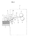
- FIGS. 1 to 6B An preferred embodiment of a paper feed unit according to the present invention will be described hereinafter in detail with reference to FIGS. 1 to 6B.
- description will be given while taking a case of applying a paper feed unit A to the paper feed section SP of a printing machine S as an example.
- the printing machine S to which the paper feed unit A is applied is suitably exemplified by a stencil printing machine or the like.
- FIG. 1 many print sheets (or sheets) 2 are stacked on the paper feed tray 1 of the paper feed unit A.
- a scraper roller 3 and a pickup roller, which are primary paper feed rollers, are located above the print sheets 2 thus stacked.
- the scraper roller 3 press-contacts with the uppermost print sheet 2 and the pickup roller 4 press-contacts with a stripper tray 5. If necessary and suitable, it is needless to say that a single roller can be used as a primary paper feed roller.
- the rotary shaft 6 of the pickup roller 4 and the rotary shaft 7 of the scraper roller 3 are coupled to each other by a driving belt V.
- the pickup roller 4 and the scraper roller 3 are rotated in paper feed rotation direction synchronously with each other by the rotation of the rotary shaft 6 of the pickup roller 4.
- a pair of secondary paper feed rollers 8 and 9 are arranged to press-contact with each other on the transfer downstream side of the pickup roller 4.
- the paired secondary paper feed rollers 8 and 9 are driven to rotate in opposite directions so as to transfer the print sheet 2 put between the rollers 8 and 9.
- a paper feed sensor 10 is provided between the pickup roller 4 and the paired secondary paper feed rollers 8 and 9.
- the paper feed sensor 10 detects the tip end of the print sheet 2 transferred from a primary paper feed side.
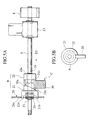
- a counter rotation stop mechanism B comprises a stopper member 21 and a one-way clutch member 22 having engagement gear teeth 21a and 22a on their respective opposite surfaces.
- Both the stopper member 21 and the one-way clutch member 22 are inserted into the rotary shaft 6.
- the stopper member 21 and the one-way clutch member 22 are constituted to be slidable in the axial direction of the rotary shaft 6 while the sliding ranges of the members 21 and 22 are restricted by left and right E rings 23 and 24 and to be movable between an engagement position at which their respective engagement gear teeth 21a and 22a are engaged with each other and a disengagement position at which the engagement gear teeth 21a and 22a are away and disengaged from each other.
- the stopper member 21 is urged against the one-way clutch member 22, i.e., urged toward the engagement position by the spring force of the slide spring 25.
- the stopper member 21 is arranged to allow the rotation of the rotary shaft 6 and engagement protrusions 21b on the outer surface of the stopper member 21 are inserted into the engagement hole 26a of a side plate 26 on a paper feed unit main body side, whereby the stopper member 21 is unable to rotate toward the side plate 26.
- An inclined face 21c is provided on the one-way clutch 22-side circumferential side surface of the stopper member 21.
- the one-way clutch member 22 is constituted to allow the rotation of the rotary shaft 6 when the rotary shaft 6 rotates in a paper feed rotation direction a and to be locked to the rotary shaft 6 when the rotary shaft 6 rotates in a paper feed counterrotating direction b.
- a rotation stop release mechanism C is provided at the rotary shaft 6.
- the mechanism C comprises the stopper member 21 and an operation lever 30 interposed between the stopper member 21 and the one-way clutch member 22.
- the operation lever 30 is provided rotatably around the rotary shaft 6, which functions as the rotary shaft of the lever 30, toward the stopper member 21 and the one-way clutch member 22.
- An inclined face 30a corresponding to the inclined face 21c of the stopper member 21 is provided on the stopper member 21-side of the operation member 30.
- the stopper member 21 and the one-way clutch member 22 realize, as a whole, a rotation stop state in which the rotation of the rotary shaft 5 in the paper feed counterrotating direction b is prevented.
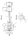
- the operation lever 30 can be rotated between the rotation position shown in FIGS. 5A and 5B and the rotation position shown in FIGS. 6A and 6B while the inclined face 30a of the operation lever 30 and the inclined face 21c of the stopper member 21 slide on each other. In a normal state, the operation lever 30 is set at the rotation position shown in FIGS. 5A and 5B.
- a one-way clutch CC is interposed between the pickup roller 4 and the rotary shaft 6.
- the one-way clutch CC is constituted so as to turn the rotary shaft 6 and the pickup roller 4 into a driving state, i.e., the rotary shaft 6 and the pickup roller 4 rotate integrally with each other when the rotary shaft 6 is driven in the paper feed rotation direction a, and, on the contrary, to turn the rotary shaft 6 and the pickup roller 4 into a driving free state, i.e., the rotary shaft 6 and also the pickup roller 4 are free from the driving force when the rotary shaft 6 is to be driven in the paper feed counterrotating direction b.
- the sheet 2 Since the print sheet 2 which has been transferred to the position between the pickup roller 4 and the stripper tray 5 is press-contacted by the pickup roller 4, the sheet 2 is transferred further in response to the rotation of the pickup roller 4.
- the uppermost print sheet 2 is applied with a transfer force by the rotation of the pickup roller 4 and the lowermost print sheet 2 is applied with a transfer resistance by the stripper tray 5, whereby only the uppermost print sheet 2 is transferred to the paired secondary paper feed rollers 8 and 9 side.
- the paper feed sensor 10 detects the tip end of the print sheet 2 transferred, the rotation of the scraper roller 3 and that of the pickup roller 4 are stopped at the point at which the print sheet 2 has been transferred by a predetermined distance with reference to this detection point.
- the print sheet 2 is contacted with the paired secondary paper feed rollers 8 and 9 while the tip end thereof is put between the paired secondary paper feed rollers 8 and 9, and transferred further from this contact position. Then, primary paper feed is completed while the print sheet 2 is being bent as shown in FIG. 1.
- secondary paper feed is started at predetermined timing and the paired secondary paper feed rollers 8 and 9 are driven to rotate.
- the bent print sheet 2 is put between the paired secondary paper feed rollers 8 and 9 smoothly and surely by the returning force of the print sheet 2 for returning to a linear state.
- the secondary paper feed is, therefore, performed accurately and surely.
- the rear end of the print sheet 2 which has been fed primarily is press-contacted with the pickup roller 4. Since the pickup roller 4 can be rotated in the paper feed rotation direction a, smooth secondary paper feed operation is surely allowed.
- the operation lever 30 is rotated from the position shown in FIGS. 5A and 5B to the position shown in FIGS. 6A and 6B. Then, the engagement gear teeth 22a of the one-way clutch member 22 and the engagement gear teeth 21a of the stopper member 21 are disengaged from each other. As a result, even if a rotation force in the paper feed counterrotating direction b acts on the rotary shaft 6, the one-way clutch member 22 itself freely rotates together with the rotary shaft 6. Accordingly, the print sheet 2 is not stopped by the one-way clutch member 22 and the stopper member 21.
- the force applied to the operation lever 30 is released so that the lever 30 is located at the position shown in FIGS. 6A and 6B. Then, the operation lever 30 automatically returns to the position shown in FIGS. 5A and 5B by the reactive force of the slide spring 25.
- the counter rotation stop mechanism B comprises the one-way clutch member 22 and the stopper member 21. Needless to say, the mechanism B should not be limited to this constitution. Any mechanisms which allow the rotation of the rotary shaft 6 in the paper feed rotation direction a and stop the rotation thereof in the paper feed counterrotating direction b are available.
- rotation stop release mechanism C comprises the operation lever 30 in this embodiment, the mechanism C should not be limited to this constitution. Any mechanisms which can release the rotation stop operation of the counter rotation stop mechanism B are available.
- the present invention should not be limited thereto. Even a printing machine and a copying machine other than the stencil printing machine are available if the machines are each provided with a paper feed section for feeding print sheets 2 stacked on a paper feed tray one by one.
- a pressing force in the counterrotating direction acts on the primary paper feed roller by the returning force of the bent paper sheet for returning to a linear state. If the counter rotation of the primary paper feed roller is stopped by the counter rotation stop mechanism and the rotation stop operation of this counter rotation stop mechanism is released by the rotation stop release mechanism and a tensile force for pulling the primarily fed sheet is applied from the paper feed tray side with a hand or the like, then the primary paper feed roller rotates in the counterrotating direction and the sheet can be pulled out. It is, therefore, possible to effectively prevent the positions of the sheets on the paper feed tray from being disordered by the primarily fed sheet and to easily, surely remove the sheet which has caused jamming during the primary paper feed.
- a pressing force in the counterrotating direction acts on the primary paper feed roller by the returning force of the bent sheet for returning to a linear state.
- the counter rotation of the primary paper feed roller is stopped by the engagement state in which the one-way clutch member and the stopper member are engaged with each other.
- the operation lever turns the on-way clutch member and the stopper member into a disengagement state, the rotation of the one-way clutch member becomes free.
- the primary paper feed roller rotates in the counterrotating direction, thereby making it possible to pull out the sheet.
- the paper feed unit constituted as stated so far can be appropriately applied to the paper feed section of a printing machine.
Landscapes
- Engineering & Computer Science (AREA)
- Mechanical Engineering (AREA)
- Sheets, Magazines, And Separation Thereof (AREA)
Abstract
Description
Claims (11)
- A paper feed unit comprising:a paper feed tray stacking sheets thereon;a primary paper feed roller;a secondary paper feed member provided downstream to the primary paper feed roller in a transferring direction of the sheets, an uppermost sheet among the sheets stacked on the paper feed tray being transferred toward the secondary paper feed member by rotation of the primary paper feed roller, the sheet being further transferred while a tip end of the sheet contacts with the secondary paper feed member, and primary paper feed being then completed while the sheet is being bent;a counter rotation stop mechanism allowing the primary paper feed roller to rotate in a paper feed direction but preventing the primary paper feed roller from rotating in a counter direction to the paper feed direction; anda rotation stop release mechanism releasing a state in which the primary paper feed roller is prevented from rotating in the counter direction b y the counter rotation stop mechanism.
- A paper feed unit according to claim 1, wherein the counter rotation stop mechanism comprises a stopper member having a first engagement section and a one-way clutch member having a second engagement section, and prevents the primary paper feed roller from rotating in the counter direction to the paper feed direction when the first engagement section of the stopper member and the second engagement section of the one-way clutch member are engaged with each other.
- A paper feed unit according to claim 2, wherein the counter rotation stop mechanism has a spring member urging the stopper member against the one-way clutch member.
- A paper feed unit according to claim 3, wherein the stopper member, the one-way clutch member and the spring member are provided to surround a rotary shaft relating to the primary paper feed roller.
- A paper feed unit according to claim 2, wherein the first engagement section of the stopper member and the second engagement section of the one-way clutch member have corresponding gear teeth, respectively.
- A paper feed unit according to any one of the preceding claims, wherein the rotation stop release mechanism is an operation lever interposed between the stopper member and the one-way clutch member.
- A paper feed unit according to claim 6, wherein the stopper member of the counter rotation stop mechanism has a first inclined face and the operation lever has a second inclined face corresponding to the first inclined face; and the first inclined face and the second inclined face slide on each other in response to a movement of the operation lever, thereby releasing the state in which the primary paper feed roller is prevented from rotating in the counter direction.
- A paper feed unit according to claim 6, wherein the operation lever has a portion surrounding the rotary shaft relating to the primary paper feed roller.
- A paper feed unit according to any one of the preceding claims, wherein the secondary paper feed member is provided with a pair of rollers.
- A paper feed unit according to claim 9, wherein after the primary paper feed, secondary paper feed is performed through the pair of rollers.
- A paper feed unit according to any one of the preceding claims, wherein the paper feed unit is used as a paper feed section of a printing machine.
Applications Claiming Priority (2)
| Application Number | Priority Date | Filing Date | Title |
|---|---|---|---|
| JP2000145582 | 2000-05-17 | ||
| JP2000145582A JP3635003B2 (en) | 2000-05-17 | 2000-05-17 | Paper feeding device and printing device using the same |
Publications (3)
| Publication Number | Publication Date |
|---|---|
| EP1170234A2 true EP1170234A2 (en) | 2002-01-09 |
| EP1170234A3 EP1170234A3 (en) | 2003-04-02 |
| EP1170234B1 EP1170234B1 (en) | 2005-04-27 |
Family
ID=18652069
Family Applications (1)
| Application Number | Title | Priority Date | Filing Date |
|---|---|---|---|
| EP01111165A Expired - Lifetime EP1170234B1 (en) | 2000-05-17 | 2001-05-10 | Paper feed unit |
Country Status (5)
| Country | Link |
|---|---|
| US (1) | US6530706B2 (en) |
| EP (1) | EP1170234B1 (en) |
| JP (1) | JP3635003B2 (en) |
| CN (1) | CN1182015C (en) |
| DE (1) | DE60110317T2 (en) |
Families Citing this family (13)
| Publication number | Priority date | Publication date | Assignee | Title |
|---|---|---|---|---|
| WO2003016138A1 (en) * | 2001-08-20 | 2003-02-27 | Yuyama Mfg. Co., Ltd. | Tablet feeder |
| JP2003341861A (en) * | 2002-05-29 | 2003-12-03 | Toshiba Tec Corp | Manual feeder |
| KR100449105B1 (en) * | 2002-09-07 | 2004-09-18 | 삼성전자주식회사 | driving apparatus having a part for releasing the driving force-latching of a feeding part in an office machine |
| KR100524078B1 (en) * | 2003-11-18 | 2005-10-26 | 삼성전자주식회사 | Automatic document feeding apparatus |
| JP4008440B2 (en) * | 2004-08-27 | 2007-11-14 | シャープ株式会社 | Image forming apparatus |
| KR100580213B1 (en) * | 2004-12-20 | 2006-05-16 | 삼성전자주식회사 | Paper pickup apparatus and image forming apparatus having same |
| JP4510899B2 (en) * | 2008-01-11 | 2010-07-28 | シャープ株式会社 | Sheet conveying apparatus, document processing apparatus and image forming apparatus using the same |
| TWI381948B (en) * | 2010-06-25 | 2013-01-11 | Primax Electronics Ltd | Pickup module of automatic feeding apparatus |
| CN102674035B (en) * | 2012-04-19 | 2014-12-24 | 苏州佳世达电通有限公司 | One-way overload protection device and paper taking device |
| JP6215136B2 (en) * | 2014-05-21 | 2017-10-18 | アルプス電気株式会社 | Image forming apparatus |
| CN108290407B (en) | 2016-01-08 | 2021-03-26 | 惠普发展公司有限责任合伙企业 | Roll lock |
| US10656587B2 (en) * | 2017-09-25 | 2020-05-19 | Canon Kabushiki Kaisha | Sheet conveying device and image forming apparatus |
| TWI862083B (en) * | 2023-08-17 | 2024-11-11 | 虹光精密工業股份有限公司 | Silent one-way clutch assembly and document scanner using the same |
Family Cites Families (15)
| Publication number | Priority date | Publication date | Assignee | Title |
|---|---|---|---|---|
| DE2123811C3 (en) * | 1970-05-18 | 1978-12-07 | Canon K.K., Tokio | Paper feeder |
| US4023254A (en) * | 1975-12-18 | 1977-05-17 | Monarch Marking Systems, Inc. | Pinning method and apparatus |
| US4735109A (en) * | 1981-07-27 | 1988-04-05 | Eaton Corporation | Semi-blocked transmission |
| JPS58172136A (en) * | 1982-03-30 | 1983-10-08 | Toshiba Corp | Separate feed device for paper leaf |
| US4519601A (en) * | 1982-12-02 | 1985-05-28 | Tokyo Shibaura Denki Kabushiki Kaisha | Sheet feeding apparatus |
| EP0157735A3 (en) * | 1984-04-02 | 1988-09-14 | Kurt Rünzi | Device for feeding sheets to the platen of an office machine |
| JPS6181334A (en) * | 1984-09-27 | 1986-04-24 | Toshiba Corp | Paper feeder |
| US4945678A (en) * | 1988-12-05 | 1990-08-07 | Truth Incorporated | Window operator |
| US5085420A (en) * | 1989-07-18 | 1992-02-04 | Canon Kabushiki Kaisha | Sheet feeding apparatus |
| JP3093431B2 (en) * | 1992-04-30 | 2000-10-03 | 株式会社リコー | Paper feeder of image forming device |
| JP3199351B2 (en) * | 1995-07-04 | 2001-08-20 | ダイワ精工株式会社 | Spinning reel |
| JP4057115B2 (en) * | 1997-06-09 | 2008-03-05 | 東北リコー株式会社 | Printing device |
| JP3526200B2 (en) * | 1997-06-24 | 2004-05-10 | 株式会社シマノ | Spinning reel rotor braking mechanism and spinning reel |
| EP0921082B1 (en) * | 1997-12-08 | 2002-06-26 | Samsung Electronics Co., Ltd. | Spring clutch control mechanism for a sheet feeding device |
| JP4293388B2 (en) * | 1998-11-10 | 2009-07-08 | 東北リコー株式会社 | Paper feeding device in printing device |
-
2000
- 2000-05-17 JP JP2000145582A patent/JP3635003B2/en not_active Expired - Lifetime
-
2001
- 2001-04-26 US US09/842,176 patent/US6530706B2/en not_active Expired - Lifetime
- 2001-05-10 DE DE60110317T patent/DE60110317T2/en not_active Expired - Lifetime
- 2001-05-10 EP EP01111165A patent/EP1170234B1/en not_active Expired - Lifetime
- 2001-05-16 CN CNB011181133A patent/CN1182015C/en not_active Expired - Fee Related
Also Published As
| Publication number | Publication date |
|---|---|
| DE60110317D1 (en) | 2005-06-02 |
| EP1170234B1 (en) | 2005-04-27 |
| JP2001328734A (en) | 2001-11-27 |
| JP3635003B2 (en) | 2005-03-30 |
| US20010043831A1 (en) | 2001-11-22 |
| CN1323732A (en) | 2001-11-28 |
| US6530706B2 (en) | 2003-03-11 |
| CN1182015C (en) | 2004-12-29 |
| EP1170234A3 (en) | 2003-04-02 |
| DE60110317T2 (en) | 2006-02-09 |
Similar Documents
| Publication | Publication Date | Title |
|---|---|---|
| EP1170234B1 (en) | Paper feed unit | |
| EP0580431B1 (en) | Paper feeding apparatus for printer | |
| US6824132B2 (en) | Sheet feeding apparatus and recording apparatus | |
| EP0314167B1 (en) | Paper feeder | |
| US5975517A (en) | Paper feeding apparatus of printing device | |
| JPH0262451B2 (en) | ||
| JP3825155B2 (en) | Stencil printing machine | |
| KR101174052B1 (en) | Paper sheet advancing device | |
| JP2619959B2 (en) | Paper feeder | |
| JPS6127841A (en) | automatic paper feeder | |
| US4616819A (en) | Paper sheet feeding arrangement | |
| JP2547978B2 (en) | Sheet material feeder | |
| JP3648165B2 (en) | Paper feed mechanism of image forming apparatus | |
| JP2001130758A (en) | Image forming device | |
| JPH04189226A (en) | Automatic paper feeding device | |
| JP2560707Y2 (en) | Paper feed clutch device | |
| JP2002332130A (en) | Sheet material feeding device, sheet material feeding method, and recording device | |
| JP3557057B2 (en) | Drive | |
| JP4922798B2 (en) | Paper sheet processing equipment | |
| JPS5992835A (en) | Paper feeding device | |
| JP2003081471A (en) | Sheet feeding apparatus and image forming apparatus having the same | |
| JP2005075525A (en) | Sheet material feeding device and recording device | |
| JP3496412B2 (en) | Image printer | |
| JP2004182417A (en) | Automatic paper feeder | |
| JPH0930673A (en) | Sheet feeding device |
Legal Events
| Date | Code | Title | Description |
|---|---|---|---|
| PUAI | Public reference made under article 153(3) epc to a published international application that has entered the european phase |
Free format text: ORIGINAL CODE: 0009012 |
|
| 17P | Request for examination filed |
Effective date: 20010510 |
|
| AK | Designated contracting states |
Kind code of ref document: A2 Designated state(s): AT BE CH CY DE DK ES FI FR GB GR IE IT LI LU MC NL PT SE TR |
|
| AX | Request for extension of the european patent |
Free format text: AL;LT;LV;MK;RO;SI |
|
| PUAL | Search report despatched |
Free format text: ORIGINAL CODE: 0009013 |
|
| AK | Designated contracting states |
Kind code of ref document: A3 Designated state(s): AT BE CH CY DE DK ES FI FR GB GR IE IT LI LU MC NL PT SE TR |
|
| AX | Request for extension of the european patent |
Extension state: AL LT LV MK RO SI |
|
| AKX | Designation fees paid |
Designated state(s): DE FR GB |
|
| 17Q | First examination report despatched |
Effective date: 20040219 |
|
| GRAP | Despatch of communication of intention to grant a patent |
Free format text: ORIGINAL CODE: EPIDOSNIGR1 |
|
| GRAS | Grant fee paid |
Free format text: ORIGINAL CODE: EPIDOSNIGR3 |
|
| GRAA | (expected) grant |
Free format text: ORIGINAL CODE: 0009210 |
|
| AK | Designated contracting states |
Kind code of ref document: B1 Designated state(s): DE FR GB |
|
| REG | Reference to a national code |
Ref country code: GB Ref legal event code: FG4D |
|
| REG | Reference to a national code |
Ref country code: IE Ref legal event code: FG4D |
|
| REF | Corresponds to: |
Ref document number: 60110317 Country of ref document: DE Date of ref document: 20050602 Kind code of ref document: P |
|
| PLBE | No opposition filed within time limit |
Free format text: ORIGINAL CODE: 0009261 |
|
| STAA | Information on the status of an ep patent application or granted ep patent |
Free format text: STATUS: NO OPPOSITION FILED WITHIN TIME LIMIT |
|
| ET | Fr: translation filed | ||
| 26N | No opposition filed |
Effective date: 20060130 |
|
| REG | Reference to a national code |
Ref country code: FR Ref legal event code: PLFP Year of fee payment: 16 |
|
| REG | Reference to a national code |
Ref country code: FR Ref legal event code: PLFP Year of fee payment: 17 |
|
| REG | Reference to a national code |
Ref country code: FR Ref legal event code: PLFP Year of fee payment: 18 |
|
| PGFP | Annual fee paid to national office [announced via postgrant information from national office to epo] |
Ref country code: DE Payment date: 20190430 Year of fee payment: 19 |
|
| PGFP | Annual fee paid to national office [announced via postgrant information from national office to epo] |
Ref country code: FR Payment date: 20190410 Year of fee payment: 19 |
|
| PGFP | Annual fee paid to national office [announced via postgrant information from national office to epo] |
Ref country code: GB Payment date: 20190508 Year of fee payment: 19 |
|
| REG | Reference to a national code |
Ref country code: DE Ref legal event code: R119 Ref document number: 60110317 Country of ref document: DE |
|
| GBPC | Gb: european patent ceased through non-payment of renewal fee |
Effective date: 20200510 |
|
| PG25 | Lapsed in a contracting state [announced via postgrant information from national office to epo] |
Ref country code: FR Free format text: LAPSE BECAUSE OF NON-PAYMENT OF DUE FEES Effective date: 20200531 Ref country code: GB Free format text: LAPSE BECAUSE OF NON-PAYMENT OF DUE FEES Effective date: 20200510 |
|
| PG25 | Lapsed in a contracting state [announced via postgrant information from national office to epo] |
Ref country code: DE Free format text: LAPSE BECAUSE OF NON-PAYMENT OF DUE FEES Effective date: 20201201 |