EP1170217A1 - Unit for processing a web of packaging material for producing sealed packages of pourable food products - Google Patents
Unit for processing a web of packaging material for producing sealed packages of pourable food products Download PDFInfo
- Publication number
- EP1170217A1 EP1170217A1 EP00830479A EP00830479A EP1170217A1 EP 1170217 A1 EP1170217 A1 EP 1170217A1 EP 00830479 A EP00830479 A EP 00830479A EP 00830479 A EP00830479 A EP 00830479A EP 1170217 A1 EP1170217 A1 EP 1170217A1
- Authority
- EP
- European Patent Office
- Prior art keywords
- station
- web
- unit
- holes
- sensor
- Prior art date
- Legal status (The legal status is an assumption and is not a legal conclusion. Google has not performed a legal analysis and makes no representation as to the accuracy of the status listed.)
- Granted
Links
- 239000005022 packaging material Substances 0.000 title claims abstract description 23
- 235000013305 food Nutrition 0.000 title claims description 13
- 238000007789 sealing Methods 0.000 claims abstract description 8
- 230000004044 response Effects 0.000 claims abstract description 5
- 238000006073 displacement reaction Methods 0.000 claims description 3
- 239000000463 material Substances 0.000 description 15
- 239000004033 plastic Substances 0.000 description 12
- 229920003023 plastic Polymers 0.000 description 12
- 239000004698 Polyethylene Substances 0.000 description 4
- -1 polyethylene Polymers 0.000 description 4
- 229920000573 polyethylene Polymers 0.000 description 4
- XAGFODPZIPBFFR-UHFFFAOYSA-N aluminium Chemical compound [Al] XAGFODPZIPBFFR-UHFFFAOYSA-N 0.000 description 3
- 229910052782 aluminium Inorganic materials 0.000 description 3
- 239000004411 aluminium Substances 0.000 description 3
- 238000001514 detection method Methods 0.000 description 3
- 230000004888 barrier function Effects 0.000 description 2
- 230000005540 biological transmission Effects 0.000 description 2
- 238000010586 diagram Methods 0.000 description 2
- 239000002657 fibrous material Substances 0.000 description 2
- 235000015203 fruit juice Nutrition 0.000 description 2
- 238000001746 injection moulding Methods 0.000 description 2
- 235000020191 long-life milk Nutrition 0.000 description 2
- 238000004519 manufacturing process Methods 0.000 description 2
- 238000004806 packaging method and process Methods 0.000 description 2
- 235000014101 wine Nutrition 0.000 description 2
- 235000007688 Lycopersicon esculentum Nutrition 0.000 description 1
- 240000003768 Solanum lycopersicum Species 0.000 description 1
- 239000007788 liquid Substances 0.000 description 1
- 239000003550 marker Substances 0.000 description 1
- 238000000034 method Methods 0.000 description 1
- 235000013336 milk Nutrition 0.000 description 1
- 239000008267 milk Substances 0.000 description 1
- 210000004080 milk Anatomy 0.000 description 1
- 238000000465 moulding Methods 0.000 description 1
- 230000003287 optical effect Effects 0.000 description 1
- 235000020200 pasteurised milk Nutrition 0.000 description 1
- 230000002093 peripheral effect Effects 0.000 description 1
- 230000008569 process Effects 0.000 description 1
- 230000009467 reduction Effects 0.000 description 1
- 235000015067 sauces Nutrition 0.000 description 1
- 239000012815 thermoplastic material Substances 0.000 description 1
- 238000011144 upstream manufacturing Methods 0.000 description 1
Images


Classifications
-
- B—PERFORMING OPERATIONS; TRANSPORTING
- B65—CONVEYING; PACKING; STORING; HANDLING THIN OR FILAMENTARY MATERIAL
- B65B—MACHINES, APPARATUS OR DEVICES FOR, OR METHODS OF, PACKAGING ARTICLES OR MATERIALS; UNPACKING
- B65B61/00—Auxiliary devices, not otherwise provided for, for operating on sheets, blanks, webs, binding material, containers or packages
- B65B61/18—Auxiliary devices, not otherwise provided for, for operating on sheets, blanks, webs, binding material, containers or packages for making package-opening or unpacking elements
- B65B61/184—Auxiliary devices, not otherwise provided for, for operating on sheets, blanks, webs, binding material, containers or packages for making package-opening or unpacking elements by applying tabs over discharge openings, e.g. over discharge openings defined by tear or score lines
-
- B—PERFORMING OPERATIONS; TRANSPORTING
- B65—CONVEYING; PACKING; STORING; HANDLING THIN OR FILAMENTARY MATERIAL
- B65B—MACHINES, APPARATUS OR DEVICES FOR, OR METHODS OF, PACKAGING ARTICLES OR MATERIALS; UNPACKING
- B65B41/00—Supplying or feeding container-forming sheets or wrapping material
- B65B41/18—Registering sheets, blanks, or webs
-
- B—PERFORMING OPERATIONS; TRANSPORTING
- B31—MAKING ARTICLES OF PAPER, CARDBOARD OR MATERIAL WORKED IN A MANNER ANALOGOUS TO PAPER; WORKING PAPER, CARDBOARD OR MATERIAL WORKED IN A MANNER ANALOGOUS TO PAPER
- B31B—MAKING CONTAINERS OF PAPER, CARDBOARD OR MATERIAL WORKED IN A MANNER ANALOGOUS TO PAPER
- B31B50/00—Making rigid or semi-rigid containers, e.g. boxes or cartons
- B31B50/006—Controlling; Regulating; Measuring; Improving safety
-
- B—PERFORMING OPERATIONS; TRANSPORTING
- B31—MAKING ARTICLES OF PAPER, CARDBOARD OR MATERIAL WORKED IN A MANNER ANALOGOUS TO PAPER; WORKING PAPER, CARDBOARD OR MATERIAL WORKED IN A MANNER ANALOGOUS TO PAPER
- B31B—MAKING CONTAINERS OF PAPER, CARDBOARD OR MATERIAL WORKED IN A MANNER ANALOGOUS TO PAPER
- B31B50/00—Making rigid or semi-rigid containers, e.g. boxes or cartons
- B31B50/74—Auxiliary operations
- B31B50/81—Forming or attaching accessories, e.g. opening devices, closures or tear strings
- B31B50/812—Applying tabs, patches, strips or strings on blanks or webs
- B31B50/8122—Applying patches
- B31B50/8123—Applying patches the blanks remaining stationary during application of the patches
Definitions
- the present invention relates to a unit for processing a web of packaging material for producing sealed packages of pourable food products.
- pourable food products such as fruit juice, pasteurized or UHT (ultra-high-temperature processed) milk, wine, tomato sauce, etc.
- UHT ultra-high-temperature processed milk
- wine tomato sauce
- etc. are sold in packages made of sterilized packaging material.
- a typical example of such a package is the parallelepiped-shaped package for liquid or pourable food products known as Tetra Brik Aseptic (registered trademark), which is formed by folding and sealing a web of laminated packaging material.
- the packaging material has a multilayer structure comprising a layer of fibrous material, e.g. paper, covered on both sides with layers of heat-seal plastic material, e.g. polyethylene.
- the packaging material also comprises a layer of oxygen-barrier material defined, for example, by an aluminium film, which is superimposed on a layer of heat-seal plastic material and is in turn covered with another layer of heat-seal plastic material eventually defining the inner face of the package contacting the food product.
- a layer of oxygen-barrier material defined, for example, by an aluminium film, which is superimposed on a layer of heat-seal plastic material and is in turn covered with another layer of heat-seal plastic material eventually defining the inner face of the package contacting the food product.
- the web of packaging material is sterilized and then fed to a forming unit on which it is folded and sealed longitudinally to form a vertical tube.
- the tube is filled with the sterilized or sterile-processed food product, and is sealed by pairs of jaws and subsequently cut at equally spaced cross sections to form pillow packs, which are then folded mechanically to form the finished, e.g. substantially parallelepiped-shaped, packages.
- the web of packaging material may be fed through a processing unit for performing various auxiliary operations, which, when producing packages with opening devices, such as pull-off tabs, screw or hinged caps, may comprise, for example, perforation of a number of through openings or holes at predetermined points on the web, and one or more operations to fix the opening devices over the holes.
- auxiliary operations which, when producing packages with opening devices, such as pull-off tabs, screw or hinged caps, may comprise, for example, perforation of a number of through openings or holes at predetermined points on the web, and one or more operations to fix the opening devices over the holes.
- the most commonly used opening devices comprise a patch defined by a small sheet of heat-seal plastic material, and which is heat sealed over a respective hole on the side of the web eventually forming the inside of the package; and a pull-off tab applied to the opposite side of the packaging material and heat sealed to the patch.
- the tab and patch adhere to each other, so that, when the tab is pulled off, the portion of the patch heat sealed to it is also removed to uncover the hole.
- the portion of the packaging material surrounding the tab is normally fitted with a frame element normally made of plastic material and supporting a removable, e.g. screw or hinged, cap for closing the respective hole.
- closable opening devices are also known to be applied by injecting plastic material directly onto the holes in the web, as described, for example, in Patent WO 98/18609.
- the web of packaging material is fed in steps through the processing unit by a feed system comprising feed rollers controlled by a servomotor in turn controlled in response to a signal generated by an optical sensor for detecting a reference element, normally a preprinted marker such as a bar code, repeated at predetermined intervals along the web.
- a feed system comprising feed rollers controlled by a servomotor in turn controlled in response to a signal generated by an optical sensor for detecting a reference element, normally a preprinted marker such as a bar code, repeated at predetermined intervals along the web.
- the size of the patches and tabs must be proportional to the maximum offset between the work position of the heat-seal stations and the holes themselves.
- the size of the tabs is a critical parameter, which directly determines the size of the frames and caps applied to the tabs, and which must therefore be kept as small as possible to avoid the obvious disadvantages in using relatively large caps.
- the processing unit comprises, in addition to the punch station, a station for injection molding closable opening devices directly onto the respective holes in the web, the portion of the web surrounding each hole must be positioned correctly inside the molding cavity, to ensure correct flow of the thermoplastic material injected into the cavity and, hence, correct sealing of the edge of the hole on both sides of the web.
- a unit for processing a web of packaging material for producing sealed packages of pourable food products comprising at least a first station for forming a number of through holes in said web; a second station for sealing said holes by applying respective opening devices by which to open the packages; a feed device for step feeding said web along a path through said first and said second station; a position sensor generating a presence signal indicating the passage, past the sensor, of reference elements on said web; and control means for controlling said feed device in response to said presence signal; characterized in that said reference elements bear a predetermined relationship with said holes in said web; said unit also comprising actuating means cooperating with said second station to move the second station in a direction parallel to said path, and activated by said control means to adjust the position of the second station as a function of said presence signal.
- Number 1 in Figure 1 indicates as a whole a unit, in accordance with the present invention, for processing a web 2 of packaging material for producing sealed packages (not shown) of pourable food products, such as pasteurized or UHT milk, fruit juice, wine, etc.
- Unit 1 may be incorporated in a packaging machine (not shown) for continuously producing said packages from web 2 of packaging material. More specifically, web 2 is folded and sealed longitudinally in known manner to form a vertical tube, which is filled with the sterilized or sterile-processed food product, is sealed at equally spaced cross sections, and undergoes successive mechanical folding operations to form the finished packages.
- Web 2 is fed through unit 1 along a path P, and is provided on one face with a number of optically detectable reference elements, e.g. preprinted markers conveniently including respective bar codes C ( Figure 4) equally spaced along path P with a spacing equal to the length of web 2 used to produce one package, minus inevitable production tolerances of web 2.
- optically detectable reference elements e.g. preprinted markers conveniently including respective bar codes C ( Figure 4) equally spaced along path P with a spacing equal to the length of web 2 used to produce one package, minus inevitable production tolerances of web 2.
- Web 2 of packaging material has a multilayer structure, and substantially comprises a layer of fibrous material, e.g. paper, covered on both sides with respective layers of heat-seal plastic material, e.g. polyethylene.
- the side of web 2 eventually forming the inner face of the package and so contacting the food product also has a layer of barrier material defined, for example, by an aluminium film in turn covered on both sides with respective layers of heat-seal plastic material, e.g. polyethylene.
- Unit 1 comprises a known punch station 3 (shown only schematically) located along a first vertical portion P1 of path P, and where web 2 is punched to form a number of openings or holes 4 ( Figure 4) - in the example shown, substantially ogival in shape - equally spaced along path P with a spacing equal to the length of the packaging material used to form one package, minus said production tolerances of web 2.
- a known punch station 3 shown only schematically located along a first vertical portion P1 of path P, and where web 2 is punched to form a number of openings or holes 4 ( Figure 4) - in the example shown, substantially ogival in shape - equally spaced along path P with a spacing equal to the length of the packaging material used to form one package, minus said production tolerances of web 2.
- Unit 1 also comprises, downstream from station 3 and in series along a second horizontal portion P2 of path P, a first and a second station 5, 6 (known and only shown schematically) for respectively applying a patch 7 and a pull-off tab 8 to each hole 4 and on opposite faces of web 2.
- patches 7 are defined by small rectangular sheets of heat-seal plastic material, and are heat sealed at station 5 over respective holes 4 on the face of web 2 eventually forming the inside of the packages; and tabs 8 are also made of heat-seal plastic material, are rectangular, and are heat sealed at station 6 to respective patches 7 on the face of web 2 eventually forming the outside of the packages. More specifically, at the end of the operations performed at stations 5 and 6, each tab 8 projects outwards with respect to respective hole 4 in web 2, and is joined to respective patch 7 over a sealing area extending close to and inwards of a lateral edge of hole 4 and defining a tear portion of patch 7, which is removed when tab 8 is pulled off.
- each tab 8 has a multilayer structure, and is defined by a layer of heat-seal plastic material, e.g. polyethylene, one face of which eventually adheres to respective patch 7; and by a layer of barrier material, normally aluminium, which is fixed to the layer of heat-seal plastic material on the opposite side to patch 7.
- a layer of heat-seal plastic material e.g. polyethylene
- barrier material normally aluminium
- Unit 1 also comprises a feed device 10 for step feeding web 2 along path P through stations 3, 5 and 6.
- feed device 10 comprises two rollers 11, 12, which cooperate with opposite faces of web 2, define a downstream end of portion P2 of path P, and are controlled by a servomotor 13; and web 2 is guided from portion P1 to portion P2 of path P by an idle guide roller 14.
- roller 11 is controlled by servomotor 13 via a first, e.g. toothed-belt, transmission 15, and in turn controls roller 12 via a second, e.g. gear, transmission (not shown).
- first e.g. toothed-belt
- second e.g. gear
- Feed device 10 - and more specifically servomotor 13 - is controlled by a control device 20 in response to a presence signal S generated by a position sensor 21, e.g. a photocell, located along path P, and indicating the passage, past sensor 21, of codes C on web 2.
- a position sensor 21 e.g. a photocell, located along path P, and indicating the passage, past sensor 21, of codes C on web 2.
- sensor 21 is located close to - in the example shown, downstream from - station 3 along path P, so that the distance between each hole 4, formed at station 3, and respective code C is unaffected by the inevitable pull on web 2 through unit 1, and detection of codes C by sensor 21 corresponds extremely accurately to detection of the respective holes 4.
- Presence signal S assumes a first, e.g. high, logic level as a code C on web 2 travels past sensor 21, and a second, e.g. low, logic level in any other condition.
- unit 1 also comprises an actuating device 22, which cooperates with station 6 to move it in a direction parallel to portion P2 of path P, and is activated by control device 20 to adjust the position of station 6 as a function of the presence signal S generated by sensor 21. More specifically, the above adjustment is made by sliding station 6 along a guide 23 shown schematically in Figure 1.
- actuating device 22 substantially comprises an electric step motor 24 carried by a fixed supporting structure 25; and a motion converting assembly 26 interposed between an output shaft 27 of motor 24 and a platelike structural portion 28 of station 6 to convert rotation of shaft 27 into linear displacement of station 6 in a direction parallel to portion P2 of path P.
- supporting structure 25 comprises a substantially rectangular base plate 30 defining a peripheral C-shaped cavity 31 facing structural portion 28 of station 6; and a substantially prismatic, cup-shaped member 32 fixed to plate 30 so as to engage cavity 31, and having a lateral opening 33 facing station 6, and a top opening 34 closed partly by an annular disk member 35 to which motor 24 is fixed coaxially.
- shaft 27 engages disk member 35 with a certain amount of radial clearance, and projects inside cup-shaped member 32.
- Assembly 26 comprises a cam member 36 fitted to shaft 27 and housed inside cup-shaped member 32; and a tappet roller 37 fitted in rotary and axially-fixed manner to an appendix 38 of structural portion 28 of station 6, and cooperating with cam member 36.
- cam member 36 is defined by a substantially cylindrical sleeve 40, from which a substantially annular, contoured flange 41 projects radially.
- Flange 41 has a cam profile defined by a curved line increasing gradually in radius, and the ends of which are joined by a substantially radial break portion.
- Cam member 36 - or more specifically sleeve 40 - is fitted coaxially, with the interposition of a bearing 42, to a cylindrical appendix 43 projecting from a bottom wall 44 ( Figure 2), opposite top opening 34, of cup-shaped member 32.
- each spring 45 has a first end fixed to a bracket 46 projecting from plate 30; and an opposite second end fixed to a pin 47 projecting from structural portion 28 of station 6.
- control device 20 receives presence signal S from sensor 21, and generates output signals C1, C2, C3, C4, C5 for controlling stations 3, 5, 6, feed device 10 and actuating device 22 respectively.
- control device 20 implements the operations described below with reference to the logic block diagram in Figure 5.
- control device 20 acquires presence signal S indicating the passage, past sensor 21, of a code C relative to a respective hole 4 in web 2 (block 50).
- Control device 20 then processes presence signal S and calculates the absolute value and sign of the time T between the actual instant code C travels past sensor 21, and the expected or programmed instant in which passage should have occurred (block 51).
- control device 20 calculates how far and in which direction cam member 36 of actuating device 22 must be rotated from its current angular position to achieve a work position of station 6 in which tab 8 is applied properly centered with respect to hole 4 (block 52). In other words, control device 20 calculates the absolute value and sign of how far station 6 must be moved by actuating device 22 for tab 8 to be heat sealed properly centered over respective hole 4.
- control device 20 As a function of the displacement determined above, control device 20 generates signal C5 to control motor 24 of actuating device 22 (block 53).
- tabs 8 are applied properly centered over respective holes 4, thus ensuring optimum sealing of holes 4 and enabling a reduction in the size of tabs 8.
- sensor 21 may detect the passage of holes 4 themselves; in which case, sensor 21 may be located at any point, between stations 3 and 6, enabling the position of station 6 to be adjusted following detection and before station 6 is activated to apply a tab 8 over the detected hole 4.
- Unit 1 may also comprise a further actuating device identical to actuating device 22 and controlled by control device 20 to adjust the position of station 5 in a direction parallel to portion P2 of path P.
- the second operation may comprise injection molding closable opening devices directly onto respective holes 4 in web 2.
Landscapes
- Engineering & Computer Science (AREA)
- Mechanical Engineering (AREA)
- Containers And Plastic Fillers For Packaging (AREA)
- Making Paper Articles (AREA)
- Auxiliary Devices For And Details Of Packaging Control (AREA)
- Basic Packing Technique (AREA)
- Controlling Rewinding, Feeding, Winding, Or Abnormalities Of Webs (AREA)
Abstract
Description
- The present invention relates to a unit for processing a web of packaging material for producing sealed packages of pourable food products.
- As is known, many pourable food products, such as fruit juice, pasteurized or UHT (ultra-high-temperature processed) milk, wine, tomato sauce, etc., are sold in packages made of sterilized packaging material.
- A typical example of such a package is the parallelepiped-shaped package for liquid or pourable food products known as Tetra Brik Aseptic (registered trademark), which is formed by folding and sealing a web of laminated packaging material. The packaging material has a multilayer structure comprising a layer of fibrous material, e.g. paper, covered on both sides with layers of heat-seal plastic material, e.g. polyethylene. In the case of aseptic packages for long-storage products, such as UHT milk, the packaging material also comprises a layer of oxygen-barrier material defined, for example, by an aluminium film, which is superimposed on a layer of heat-seal plastic material and is in turn covered with another layer of heat-seal plastic material eventually defining the inner face of the package contacting the food product.
- As is known, such packages are made on fully automatic packaging machines, on which a continuous tube is formed from the packaging material supplied in web form.
- More specifically, the web of packaging material is sterilized and then fed to a forming unit on which it is folded and sealed longitudinally to form a vertical tube. The tube is filled with the sterilized or sterile-processed food product, and is sealed by pairs of jaws and subsequently cut at equally spaced cross sections to form pillow packs, which are then folded mechanically to form the finished, e.g. substantially parallelepiped-shaped, packages.
- Upstream from the forming unit, the web of packaging material may be fed through a processing unit for performing various auxiliary operations, which, when producing packages with opening devices, such as pull-off tabs, screw or hinged caps, may comprise, for example, perforation of a number of through openings or holes at predetermined points on the web, and one or more operations to fix the opening devices over the holes.
- The most commonly used opening devices comprise a patch defined by a small sheet of heat-seal plastic material, and which is heat sealed over a respective hole on the side of the web eventually forming the inside of the package; and a pull-off tab applied to the opposite side of the packaging material and heat sealed to the patch. The tab and patch adhere to each other, so that, when the tab is pulled off, the portion of the patch heat sealed to it is also removed to uncover the hole.
- To close the package once the tab is pulled off, the portion of the packaging material surrounding the tab is normally fitted with a frame element normally made of plastic material and supporting a removable, e.g. screw or hinged, cap for closing the respective hole.
- Alternatively, closable opening devices are also known to be applied by injecting plastic material directly onto the holes in the web, as described, for example, in Patent WO 98/18609.
- On known machines, the web of packaging material is fed in steps through the processing unit by a feed system comprising feed rollers controlled by a servomotor in turn controlled in response to a signal generated by an optical sensor for detecting a reference element, normally a preprinted marker such as a bar code, repeated at predetermined intervals along the web.
- In the case of processing units comprising a punch station, and two heat-seal stations for applying the patches and pull-off tabs respectively, a high degree of precision is required in positioning the web, especially at the tab seal station.
- That is, to ensure perfect sealing of the holes in the web, the size of the patches and tabs must be proportional to the maximum offset between the work position of the heat-seal stations and the holes themselves. The size of the tabs, however, is a critical parameter, which directly determines the size of the frames and caps applied to the tabs, and which must therefore be kept as small as possible to avoid the obvious disadvantages in using relatively large caps.
- Similarly, when the processing unit comprises, in addition to the punch station, a station for injection molding closable opening devices directly onto the respective holes in the web, the portion of the web surrounding each hole must be positioned correctly inside the molding cavity, to ensure correct flow of the thermoplastic material injected into the cavity and, hence, correct sealing of the edge of the hole on both sides of the web.
- A demand therefore exists within the industry for even greater precision in processing the web at each station on the unit.
- It is an object of the present invention to provide a unit for processing a web of packaging material for producing sealed packages of pourable food products, and which provides for a high degree of precision in the performance of at least two successive operations on the same portion of the web.
- According to the present invention, there is provided a unit for processing a web of packaging material for producing sealed packages of pourable food products, said unit comprising at least a first station for forming a number of through holes in said web; a second station for sealing said holes by applying respective opening devices by which to open the packages; a feed device for step feeding said web along a path through said first and said second station; a position sensor generating a presence signal indicating the passage, past the sensor, of reference elements on said web; and control means for controlling said feed device in response to said presence signal; characterized in that said reference elements bear a predetermined relationship with said holes in said web; said unit also comprising actuating means cooperating with said second station to move the second station in a direction parallel to said path, and activated by said control means to adjust the position of the second station as a function of said presence signal.
- A preferred, non-limiting embodiment of the present invention will be described by way of example with reference to the accompanying drawings, in which:
- Figure 1 shows a schematic side view of a unit, in accordance with the present invention, for processing a web of packaging material for producing sealed packages of pourable food products;
- Figure 2 shows a partly sectioned, larger-scale side view of an actuating assembly of the Figure 1 unit;
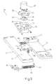
- Figure 3 shows a smaller-scale exploded view in perspective of the Figure 2 actuating assembly;
- Figure 4 shows a view in perspective of a portion of the web during processing;
- Figure 5 shows a logic block diagram illustrating part of the operation of a control device on the Figure 1 unit.
-
- Number 1 in Figure 1 indicates as a whole a unit, in accordance with the present invention, for processing a
web 2 of packaging material for producing sealed packages (not shown) of pourable food products, such as pasteurized or UHT milk, fruit juice, wine, etc. - Unit 1 may be incorporated in a packaging machine (not shown) for continuously producing said packages from
web 2 of packaging material. More specifically,web 2 is folded and sealed longitudinally in known manner to form a vertical tube, which is filled with the sterilized or sterile-processed food product, is sealed at equally spaced cross sections, and undergoes successive mechanical folding operations to form the finished packages. -
Web 2 is fed through unit 1 along a path P, and is provided on one face with a number of optically detectable reference elements, e.g. preprinted markers conveniently including respective bar codes C (Figure 4) equally spaced along path P with a spacing equal to the length ofweb 2 used to produce one package, minus inevitable production tolerances ofweb 2. -
Web 2 of packaging material has a multilayer structure, and substantially comprises a layer of fibrous material, e.g. paper, covered on both sides with respective layers of heat-seal plastic material, e.g. polyethylene. The side ofweb 2 eventually forming the inner face of the package and so contacting the food product also has a layer of barrier material defined, for example, by an aluminium film in turn covered on both sides with respective layers of heat-seal plastic material, e.g. polyethylene. - Unit 1 comprises a known punch station 3 (shown only schematically) located along a first vertical portion P1 of path P, and where
web 2 is punched to form a number of openings or holes 4 (Figure 4) - in the example shown, substantially ogival in shape - equally spaced along path P with a spacing equal to the length of the packaging material used to form one package, minus said production tolerances ofweb 2. - Unit 1 also comprises, downstream from station 3 and in series along a second horizontal portion P2 of path P, a first and a
second station 5, 6 (known and only shown schematically) for respectively applying a patch 7 and a pull-off tab 8 to eachhole 4 and on opposite faces ofweb 2. - More specifically, patches 7 are defined by small rectangular sheets of heat-seal plastic material, and are heat sealed at
station 5 overrespective holes 4 on the face ofweb 2 eventually forming the inside of the packages; and tabs 8 are also made of heat-seal plastic material, are rectangular, and are heat sealed atstation 6 to respective patches 7 on the face ofweb 2 eventually forming the outside of the packages. More specifically, at the end of the operations performed atstations respective hole 4 inweb 2, and is joined to respective patch 7 over a sealing area extending close to and inwards of a lateral edge ofhole 4 and defining a tear portion of patch 7, which is removed when tab 8 is pulled off. - Like
web 2 of packaging material, each tab 8 has a multilayer structure, and is defined by a layer of heat-seal plastic material, e.g. polyethylene, one face of which eventually adheres to respective patch 7; and by a layer of barrier material, normally aluminium, which is fixed to the layer of heat-seal plastic material on the opposite side to patch 7. - Unit 1 also comprises a
feed device 10 forstep feeding web 2 along path P throughstations - More specifically,
feed device 10 comprises tworollers web 2, define a downstream end of portion P2 of path P, and are controlled by aservomotor 13; andweb 2 is guided from portion P1 to portion P2 of path P by anidle guide roller 14. - More specifically,
roller 11 is controlled byservomotor 13 via a first, e.g. toothed-belt,transmission 15, and inturn controls roller 12 via a second, e.g. gear, transmission (not shown). - Feed device 10 - and more specifically servomotor 13 - is controlled by a
control device 20 in response to a presence signal S generated by aposition sensor 21, e.g. a photocell, located along path P, and indicating the passage,past sensor 21, of codes C onweb 2. - More specifically,
sensor 21 is located close to - in the example shown, downstream from - station 3 along path P, so that the distance between eachhole 4, formed at station 3, and respective code C is unaffected by the inevitable pull onweb 2 through unit 1, and detection of codes C bysensor 21 corresponds extremely accurately to detection of therespective holes 4. - Presence signal S assumes a first, e.g. high, logic level as a code C on
web 2 travels pastsensor 21, and a second, e.g. low, logic level in any other condition. - An important aspect of the present invention is that unit 1 also comprises an
actuating device 22, which cooperates withstation 6 to move it in a direction parallel to portion P2 of path P, and is activated bycontrol device 20 to adjust the position ofstation 6 as a function of the presence signal S generated bysensor 21. More specifically, the above adjustment is made by slidingstation 6 along aguide 23 shown schematically in Figure 1. - With reference to Figures 2 and 3,
actuating device 22 substantially comprises anelectric step motor 24 carried by a fixed supportingstructure 25; and amotion converting assembly 26 interposed between anoutput shaft 27 ofmotor 24 and a platelikestructural portion 28 ofstation 6 to convert rotation ofshaft 27 into linear displacement ofstation 6 in a direction parallel to portion P2 of path P. - More specifically, supporting
structure 25 comprises a substantiallyrectangular base plate 30 defining a peripheral C-shaped cavity 31 facingstructural portion 28 ofstation 6; and a substantially prismatic, cup-shaped member 32 fixed toplate 30 so as to engagecavity 31, and having alateral opening 33 facingstation 6, and atop opening 34 closed partly by anannular disk member 35 to whichmotor 24 is fixed coaxially. - As shown in Figures 2 and 3,
shaft 27 engagesdisk member 35 with a certain amount of radial clearance, and projects inside cup-shaped member 32. -
Assembly 26 comprises acam member 36 fitted toshaft 27 and housed inside cup-shapedmember 32; and atappet roller 37 fitted in rotary and axially-fixed manner to anappendix 38 ofstructural portion 28 ofstation 6, and cooperating withcam member 36. - More specifically,
cam member 36 is defined by a substantiallycylindrical sleeve 40, from which a substantially annular, contouredflange 41 projects radially.Flange 41 has a cam profile defined by a curved line increasing gradually in radius, and the ends of which are joined by a substantially radial break portion. - Cam member 36 - or more specifically sleeve 40 - is fitted coaxially, with the interposition of a bearing 42, to a
cylindrical appendix 43 projecting from a bottom wall 44 (Figure 2), opposite top opening 34, of cup-shaped member 32. -
Cam member 36 andtappet roller 37 are maintained contacting by twogarter springs 45 interposed betweenplate 30 andstructural portion 28 ofstation 6, and having respective axes parallel to portion P2 of path P. More specifically, eachspring 45 has a first end fixed to abracket 46 projecting fromplate 30; and an opposite second end fixed to apin 47 projecting fromstructural portion 28 ofstation 6. - With reference to Figure 1,
control device 20 receives presence signal S fromsensor 21, and generates output signals C1, C2, C3, C4, C5 for controllingstations feed device 10 andactuating device 22 respectively. - More specifically, to adjust the position of
station 6 before each tab 8 is applied to arespective hole 4 inweb 2,control device 20 implements the operations described below with reference to the logic block diagram in Figure 5. - As shown in Figure 5,
control device 20 acquires presence signal S indicating the passage,past sensor 21, of a code C relative to arespective hole 4 in web 2 (block 50). -
Control device 20 then processes presence signal S and calculates the absolute value and sign of the time T between the actual instant code C travels pastsensor 21, and the expected or programmed instant in which passage should have occurred (block 51). - As a function of time T determined above and of the traveling speed of
web 2,control device 20 calculates how far and in whichdirection cam member 36 of actuatingdevice 22 must be rotated from its current angular position to achieve a work position ofstation 6 in which tab 8 is applied properly centered with respect to hole 4 (block 52). In other words,control device 20 calculates the absolute value and sign of how farstation 6 must be moved by actuatingdevice 22 for tab 8 to be heat sealed properly centered overrespective hole 4. - As a function of the displacement determined above,
control device 20 generates signal C5 to controlmotor 24 of actuating device 22 (block 53). - The advantages of unit 1 according to the present invention will be clear from the foregoing description.
- In particular, detecting the actual location of each
hole 4 inweb 2 by means ofsensor 21, and by adjusting the position ofstation 6 each time as a function of presence signal S generated bysensor 21, tabs 8 are applied properly centered overrespective holes 4, thus ensuring optimum sealing ofholes 4 and enabling a reduction in the size of tabs 8. - Clearly, changes may be made to unit 1 as described and illustrated herein without, however, departing from the scope of the accompanying Claims.
- In particular, as opposed to codes C,
sensor 21 may detect the passage ofholes 4 themselves; in which case,sensor 21 may be located at any point, betweenstations 3 and 6, enabling the position ofstation 6 to be adjusted following detection and beforestation 6 is activated to apply a tab 8 over the detectedhole 4. - Unit 1 may also comprise a further actuating device identical to actuating
device 22 and controlled bycontrol device 20 to adjust the position ofstation 5 in a direction parallel to portion P2 of path P. - Finally, different operations may be performed downstream from the punch operation; for example, the second operation may comprise injection molding closable opening devices directly onto
respective holes 4 inweb 2.
Claims (10)
- A unit (1) for processing a web (2) of packaging material for producing sealed packages of pourable food products, said unit (1) comprising at least a first station (3) for forming a number of through holes (4) in said web (2); a second station (6) for sealing said holes by applying respective opening devices (7, 8) by which to open the packages; a feed device (10) for step feeding said web (2) along a path (P) through said first and said second station (3, 6); a position sensor (21) generating a presence signal (S) indicating the passage, past the sensor (21), of reference elements (C; 4) on said web (2); and control means (20) for controlling said feed device (10) in response to said presence signal (S); characterized in that said reference elements (C; 4) bear a predetermined relationship with said holes (4) in said web (2); said unit (1) also comprising actuating means (22) cooperating with said second station (6) to move the second station in a direction parallel to said path (P), and activated by said control means (20) to adjust the position of the second station (6) as a function of said presence signal (S).
- A unit as claimed in Claim 1, characterized in that said control means (20) comprise acquiring means (50) for acquiring said presence signal (S); and generating means (53) for generating an adjusting signal (C5) for said actuating means (22) as a function of the time interval (T) between the actual instant at which the passage of a said reference element (C; 4) past said sensor (21) occurs, and an expected instant for said passage.
- A unit as claimed in Claim 2, characterized in that said control means (20) comprise first calculating means (51) for determining the absolute value and sign of said time intervals (T); and second calculating means (52) for determining, as a function of each said time interval (T) and the traveling speed of said web (2), the absolute value and sign of the required displacement of said second station (6) for each said opening device (7, 8) to be applied centrally over the respective said hole (4) in said web (2).
- A unit as claimed in any one of the foregoing Claims, characterized in that said sensor (21) is located close to said first station (3).
- A unit as claimed in any one of the foregoing Claims, characterized in that said sensor (21) is located downstream from said first station (3) along said path (P).
- A unit as claimed in any one of the foregoing Claims, characterized in that said reference elements are preprinted codes (C) repeated along said web (2) of packaging material.
- A unit as claimed in Claim 6, characterized in that said preprinted codes are bar codes (C).
- A unit as claimed in any one of Claims 1 to 5, characterized in that said reference elements are defined by said holes (4) formed at said first station (3).
- A unit as claimed in any one of the foregoing Claims, characterized in that each said opening device comprises a pull-off tab (8) and a patch (7), which are sealed to each other and applied to opposite faces of said web (2) at a respective said hole (4); said second station being a station (6) for applying said pull-off tabs (8); and said unit (1) also comprising a third station (5) for applying said patches (7) and interposed between said first and said second station (3, 6).
- A unit as claimed in any one of the foregoing Claims, characterized in that said second station (6) is mounted to slide along a guide (23) in a direction parallel to said path (P); and in that said actuating means (22) comprise an electric motor (24), and cam and tappet means (36, 37) interposed between an output shaft (27) of said motor (24) and a structural portion (28) of said second station (6).
Priority Applications (14)
| Application Number | Priority Date | Filing Date | Title |
|---|---|---|---|
| DE60003301T DE60003301T2 (en) | 2000-07-07 | 2000-07-07 | Unit for processing a packaging material web for the production of sealed packs with flowable foods |
| ES00830479T ES2199758T3 (en) | 2000-07-07 | 2000-07-07 | UNIT TO PROCESS A BAG OF PACKING MATERIAL TO PRODUCE PACKS OF FOOD PRODUCTS THAT CAN BE VERTER. |
| AT00830479T ATE242725T1 (en) | 2000-07-07 | 2000-07-07 | UNIT FOR PROCESSING A WEB OF PACKAGING MATERIAL FOR PRODUCING SEALED PACKAGINGS OF FLOWABLE FOODS |
| PT00830479T PT1170217E (en) | 2000-07-07 | 2000-07-07 | A PROCESSING UNIT FOR A BODY DEMATERIAL BAND FOR PRODUCTION OF SEALED PACKAGING OF VAZABLE FOOD PRODUCTS |
| EP00830479A EP1170217B1 (en) | 2000-07-07 | 2000-07-07 | Unit for processing a web of packaging material for producing sealed packages of pourable food products |
| DK00830479T DK1170217T3 (en) | 2000-07-07 | 2000-07-07 | Unit for processing a web of packaging material for the production of sealed packages of liquid foods |
| HK04100849.9A HK1058028B (en) | 2000-07-07 | 2001-07-06 | Unit for processing a web of packaging material |
| US10/312,835 US7033310B2 (en) | 2000-07-07 | 2001-07-06 | Unit for processing a web of packaging material |
| PCT/EP2001/007772 WO2002004296A1 (en) | 2000-07-07 | 2001-07-06 | Unit for processing a web of packaging material |
| MXPA02012590A MXPA02012590A (en) | 2000-07-07 | 2001-07-06 | Unit for processing a web of packaging material. |
| CNB018124720A CN1188320C (en) | 2000-07-07 | 2001-07-06 | Unit for processing web of packaging material |
| JP2002508975A JP4744780B2 (en) | 2000-07-07 | 2001-07-06 | Unit for processing a web of packaging material |
| BRPI0112221-5A BR0112221B1 (en) | 2000-07-07 | 2001-07-06 | unit to process a continuous sheet of packaging material. |
| AU2001277527A AU2001277527A1 (en) | 2000-07-07 | 2001-07-06 | Unit for processing a web of packaging material |
Applications Claiming Priority (1)
| Application Number | Priority Date | Filing Date | Title |
|---|---|---|---|
| EP00830479A EP1170217B1 (en) | 2000-07-07 | 2000-07-07 | Unit for processing a web of packaging material for producing sealed packages of pourable food products |
Publications (2)
| Publication Number | Publication Date |
|---|---|
| EP1170217A1 true EP1170217A1 (en) | 2002-01-09 |
| EP1170217B1 EP1170217B1 (en) | 2003-06-11 |
Family
ID=8175396
Family Applications (1)
| Application Number | Title | Priority Date | Filing Date |
|---|---|---|---|
| EP00830479A Expired - Lifetime EP1170217B1 (en) | 2000-07-07 | 2000-07-07 | Unit for processing a web of packaging material for producing sealed packages of pourable food products |
Country Status (13)
| Country | Link |
|---|---|
| US (1) | US7033310B2 (en) |
| EP (1) | EP1170217B1 (en) |
| JP (1) | JP4744780B2 (en) |
| CN (1) | CN1188320C (en) |
| AT (1) | ATE242725T1 (en) |
| AU (1) | AU2001277527A1 (en) |
| BR (1) | BR0112221B1 (en) |
| DE (1) | DE60003301T2 (en) |
| DK (1) | DK1170217T3 (en) |
| ES (1) | ES2199758T3 (en) |
| MX (1) | MXPA02012590A (en) |
| PT (1) | PT1170217E (en) |
| WO (1) | WO2002004296A1 (en) |
Cited By (5)
| Publication number | Priority date | Publication date | Assignee | Title |
|---|---|---|---|---|
| EP1584562A1 (en) * | 2004-03-29 | 2005-10-12 | ILAPAK Research & Development S.A. | Station for applying segments of openable/reclosable strip on a plastic film web destined to form bags |
| EP2025815A2 (en) | 2007-08-13 | 2009-02-18 | Triopan Dähler AG | Tripod for folding sign |
| EP2357138A1 (en) * | 2010-02-12 | 2011-08-17 | Tetra Laval Holdings & Finance S.A. | Device and method for feeding a web of a packaging material |
| WO2014192984A3 (en) * | 2013-09-10 | 2015-02-12 | ユニ・チャーム株式会社 | Manufacturing method for packaged body of sanitary articles, and manufacturing device |
| FR3068639A1 (en) * | 2017-07-06 | 2019-01-11 | Robert Bosch Gmbh | DEVICE FOR INFLUENCING A FILM IN A THERMOFORMING FACILITY |
Families Citing this family (8)
| Publication number | Priority date | Publication date | Assignee | Title |
|---|---|---|---|---|
| SE0302493D0 (en) * | 2003-09-19 | 2003-09-19 | Tetra Laval Holdings & Finance | Ways of controllably transporting an object and devices for transporting runway |
| JP4819110B2 (en) * | 2008-10-28 | 2011-11-24 | トタニ技研工業株式会社 | Bag making machine |
| AU2012201647B2 (en) * | 2011-04-18 | 2016-05-05 | Tna Australia Pty Limited | A barcode scanner |
| NO2848399T3 (en) * | 2013-09-13 | 2018-02-10 | ||
| EP3012782B2 (en) | 2014-10-22 | 2019-10-23 | Textilma Ag | Web processing system and method for processing a base web |
| WO2017136404A1 (en) * | 2016-02-05 | 2017-08-10 | The Procter & Gamble Company | Method and apparatus for detecting holes in substrates in absorbent article converting lines |
| CN107806845B (en) * | 2017-12-06 | 2025-12-05 | 纷美(北京)贸易有限公司 | Packaging materials, methods and devices for detecting lateral offset of packaging materials, filling machines |
| EP3822071A1 (en) * | 2019-11-13 | 2021-05-19 | Tetra Laval Holdings & Finance S.A. | Unit and method for applying opening devices to a web of packaging material |
Citations (2)
| Publication number | Priority date | Publication date | Assignee | Title |
|---|---|---|---|---|
| US4782987A (en) * | 1986-01-28 | 1988-11-08 | Tetra Pak International Ab | Method for the feeding of a material web |
| WO1998018609A1 (en) | 1996-10-31 | 1998-05-07 | Tetra Laval Holdings & Finance Sa | Method and mould tools for injection moulding a plastics material part in a packaging sheet material |
Family Cites Families (30)
| Publication number | Priority date | Publication date | Assignee | Title |
|---|---|---|---|---|
| US3325335A (en) * | 1964-06-05 | 1967-06-13 | Tetra Pak Ab | Device for applying covering wafers, labels of the like to a continuously or intermittently advanced web of material |
| GB1383514A (en) * | 1971-12-22 | 1974-02-12 | Tetra Pak Dev | Apparatus for treating webs of material |
| SE390803B (en) * | 1973-09-14 | 1977-01-24 | Ziristor Ab | DEVICE FOR FEEDING AND CUTTING A PASSED PACKAGING MATERIAL PATH |
| SE401340B (en) * | 1974-06-28 | 1978-05-02 | Tetra Pak Dev | DEVICE FOR FORMING A PACKAGING MATERIAL PATH IN A PACKAGING MACHINE |
| SE391904B (en) * | 1974-06-28 | 1977-03-07 | Tetra Pak Dev | BODIES FOR THE PREPARATION OF FILLERS AND THE FORMATION OF A MATERIAL PATH IN A PACKAGING MACHINE |
| SE398636B (en) * | 1974-10-11 | 1978-01-09 | Ziristor Ab | WAY TO JOIN ONE FROM A ROLL TO A PROCESSING MACHINE RUNNING WITH A REGULAR MONSTER EQUIPPED WITH THE MATERIAL PATH AND A DEVICE FOR PERFORMING THE SET |
| CH621733A5 (en) * | 1976-12-10 | 1981-02-27 | Tetra Pak Dev | |
| SE7704647L (en) * | 1977-04-22 | 1978-10-23 | Tetra Pak Int | SET AND DEVICE FOR SOLVING MATERIAL PATHS |
| SE407043B (en) * | 1977-11-29 | 1979-03-12 | Tetra Pak Int | DEVICE FOR ALTERNATE FEEDING OF A FRONT AND A REAR PART OF A PACKAGING MATERIAL PATH |
| SE429212B (en) * | 1978-04-25 | 1983-08-22 | Tetra Pak Int | DEVICE FOR PROCESSING CURRENT MATERIALS |
| SE429941B (en) * | 1978-08-22 | 1983-10-10 | Tetra Pak Dev | SET AND DEVICE FOR MANUFACTURING A MATERIAL COAT OF FOAMED THERMOPLASTIC |
| SE434256B (en) * | 1979-09-26 | 1984-07-16 | Tetra Pak Int | SET FOR MANUFACTURING A PRINTED, PREVENTED AND OPENING INSTRUCTIONS PROVIDED PACKAGING MATERIAL COVER |
| SE450829B (en) * | 1981-02-25 | 1987-08-03 | Tetra Pak Ab | SET AND DEVICE FOR PROMOTING A MATERIAL COURSE IN REGISTERED WITH A BIG LINING SAMPLE SIZE |
| SE8106547L (en) * | 1981-11-05 | 1983-04-11 | Tetra Pak Int | SET TO MAKE COAT PACK Laminate |
| DE3275918D1 (en) * | 1981-12-29 | 1987-05-07 | Tetra Pak Int | A method for the conversion of a packing laminate web from a primary form to a secondary form |
| SE454584B (en) * | 1982-04-13 | 1988-05-16 | Tetra Pak Ab | DEVICE FOR PROCESSING A TUB-SHAPED MATERIAL COVER |
| SE436023B (en) * | 1983-03-31 | 1984-11-05 | Tetra Pak Int | ROOTABLE WINDS FOR INTERVENTION IN REGISTERS WITH A BIG LINE-TARGED MATERIAL RANGE ROOTABLE WINDS FOR INTERVENTION IN REGISTERS WITH A BIG LINE-TARGED MATERIALS RANGE |
| GB2172550B (en) * | 1985-01-24 | 1988-11-16 | Svecia Antiqua Ltd | A method for the manufacture of a material in the form of paper sheets or a paper web provided with a watermarklike pattern. |
| US5161350A (en) * | 1988-11-09 | 1992-11-10 | Kennak U.S.A. Inc. | Process and apparatus for manufacturing a dispenser-container |
| JPH03157815A (en) * | 1989-11-15 | 1991-07-05 | Sekisui Chem Co Ltd | Disk taking-out jig |
| SE502583C2 (en) * | 1992-04-02 | 1995-11-20 | Tetra Laval Holdings & Finance | Ways of producing packaging material in the form of a web |
| IT1266259B1 (en) * | 1993-02-19 | 1996-12-27 | Azionaria Costruzioni Acma Spa | COMPACTING UNIT OF GROUPS OF FLAT PRODUCTS ARRANGED SIDE BY CUTTING. |
| US5749657A (en) * | 1996-05-10 | 1998-05-12 | Reynolds Consumer Products Inc. | Flexible package with hanghole and tear string and method and apparatus for making the same |
| US5733236A (en) * | 1996-12-19 | 1998-03-31 | Fmc Corporation | Bag-making apparatus having automated positioning of attachments |
| US5833107A (en) * | 1997-03-04 | 1998-11-10 | Ro-An Industries Corporation | Apparatus for drawing, a web through a synchronization section of a bag making machine |
| JPH10338244A (en) * | 1997-06-03 | 1998-12-22 | Houseki Planning:Kk | Sealed bag with tape stuck thereto and its production |
| US6217497B1 (en) * | 1998-11-09 | 2001-04-17 | Profile Packaging, Inc. | Stand-up apparatus for producing flexible pouches |
| DE19856648A1 (en) * | 1998-12-09 | 2000-06-15 | Lemo Maschb Gmbh | Method and device for positioning a plurality of processing devices arranged at a distance from one another along a movement path of a material web, in particular a plastic film web |
| SE521876C2 (en) * | 1999-12-22 | 2003-12-16 | Tetra Laval Holdings & Finance | Multi-stage unit for processing a web-shaped packaging material in a food packaging machine |
| ES2245706T3 (en) * | 2000-11-24 | 2006-01-16 | Cfs Germany Gmbh | PROCEDURE AND DEVICE FOR PLACING FILM BANDS OF A PACKING DEVICE. |
-
2000
- 2000-07-07 DK DK00830479T patent/DK1170217T3/en active
- 2000-07-07 DE DE60003301T patent/DE60003301T2/en not_active Expired - Lifetime
- 2000-07-07 PT PT00830479T patent/PT1170217E/en unknown
- 2000-07-07 AT AT00830479T patent/ATE242725T1/en active
- 2000-07-07 ES ES00830479T patent/ES2199758T3/en not_active Expired - Lifetime
- 2000-07-07 EP EP00830479A patent/EP1170217B1/en not_active Expired - Lifetime
-
2001
- 2001-07-06 AU AU2001277527A patent/AU2001277527A1/en not_active Abandoned
- 2001-07-06 WO PCT/EP2001/007772 patent/WO2002004296A1/en not_active Ceased
- 2001-07-06 JP JP2002508975A patent/JP4744780B2/en not_active Expired - Fee Related
- 2001-07-06 US US10/312,835 patent/US7033310B2/en not_active Expired - Lifetime
- 2001-07-06 CN CNB018124720A patent/CN1188320C/en not_active Expired - Fee Related
- 2001-07-06 BR BRPI0112221-5A patent/BR0112221B1/en not_active IP Right Cessation
- 2001-07-06 MX MXPA02012590A patent/MXPA02012590A/en active IP Right Grant
Patent Citations (2)
| Publication number | Priority date | Publication date | Assignee | Title |
|---|---|---|---|---|
| US4782987A (en) * | 1986-01-28 | 1988-11-08 | Tetra Pak International Ab | Method for the feeding of a material web |
| WO1998018609A1 (en) | 1996-10-31 | 1998-05-07 | Tetra Laval Holdings & Finance Sa | Method and mould tools for injection moulding a plastics material part in a packaging sheet material |
Cited By (10)
| Publication number | Priority date | Publication date | Assignee | Title |
|---|---|---|---|---|
| EP1584562A1 (en) * | 2004-03-29 | 2005-10-12 | ILAPAK Research & Development S.A. | Station for applying segments of openable/reclosable strip on a plastic film web destined to form bags |
| US7341085B2 (en) | 2004-03-29 | 2008-03-11 | Ilapak Research & Development S.A. | Station for applying segments of openable/reclosable strip on a plastic film web destined to form bags |
| EP2025815A2 (en) | 2007-08-13 | 2009-02-18 | Triopan Dähler AG | Tripod for folding sign |
| EP2357138A1 (en) * | 2010-02-12 | 2011-08-17 | Tetra Laval Holdings & Finance S.A. | Device and method for feeding a web of a packaging material |
| WO2011098591A1 (en) * | 2010-02-12 | 2011-08-18 | Tetra Laval Holdings & Finance S.A. | Device and method for feeding a web of a packaging material |
| US9132930B2 (en) | 2010-02-12 | 2015-09-15 | Tetra Laval Holdings & Finance S.A. | Device and method for feeding a web of a packaging material |
| WO2014192984A3 (en) * | 2013-09-10 | 2015-02-12 | ユニ・チャーム株式会社 | Manufacturing method for packaged body of sanitary articles, and manufacturing device |
| JP2015054691A (en) * | 2013-09-10 | 2015-03-23 | ユニ・チャーム株式会社 | Manufacturing method and device of package of hygienic article |
| CN105358437B (en) * | 2013-09-10 | 2017-03-15 | 尤妮佳股份有限公司 | Manufacture method and manufacturing equipment for the packaging of hygienic article |
| FR3068639A1 (en) * | 2017-07-06 | 2019-01-11 | Robert Bosch Gmbh | DEVICE FOR INFLUENCING A FILM IN A THERMOFORMING FACILITY |
Also Published As
| Publication number | Publication date |
|---|---|
| MXPA02012590A (en) | 2003-05-14 |
| ATE242725T1 (en) | 2003-06-15 |
| AU2001277527A1 (en) | 2002-01-21 |
| EP1170217B1 (en) | 2003-06-11 |
| HK1058028A1 (en) | 2004-04-30 |
| BR0112221B1 (en) | 2010-06-29 |
| CN1440348A (en) | 2003-09-03 |
| CN1188320C (en) | 2005-02-09 |
| BR0112221A (en) | 2003-05-06 |
| ES2199758T3 (en) | 2004-03-01 |
| DK1170217T3 (en) | 2003-09-15 |
| US7033310B2 (en) | 2006-04-25 |
| PT1170217E (en) | 2003-10-31 |
| DE60003301T2 (en) | 2004-04-29 |
| WO2002004296A1 (en) | 2002-01-17 |
| US20040038789A1 (en) | 2004-02-26 |
| JP2004502578A (en) | 2004-01-29 |
| DE60003301D1 (en) | 2003-07-17 |
| JP4744780B2 (en) | 2011-08-10 |
Similar Documents
| Publication | Publication Date | Title |
|---|---|---|
| EP1170217B1 (en) | Unit for processing a web of packaging material for producing sealed packages of pourable food products | |
| EP1914168B1 (en) | Process of manufacturing sealed packages containing a pourable food product and packaging equipment for performing such process | |
| EP2376331B1 (en) | Pressure device for exerting pressure on an opening device fitted to a package of a food product pourable into a tube of packaging material | |
| EP3378792B1 (en) | Guiding device | |
| EP2357138B1 (en) | Device and method for feeding a web of a packaging material | |
| WO2002004312A1 (en) | Packaging material for packaging pourable food products, and package made therefrom | |
| EP1110867B1 (en) | Multi-stage unit for processing a web packaging material in a food product packaging machine | |
| US10286583B2 (en) | Unit and a method for carrying out a first operation and a second operation on a web | |
| EP2418154A1 (en) | Method and unit for detecting the effective position of an opening device applied onto a sealed package | |
| EP1215123A1 (en) | Device for controlling the position of packages on a production line | |
| US8038924B2 (en) | Method of controllably conveying an object and an apparatus for conveying a web | |
| HK1058028B (en) | Unit for processing a web of packaging material | |
| EP1215143A1 (en) | Conveyor assembly for a unit for applying opening devices to sealed packages |
Legal Events
| Date | Code | Title | Description |
|---|---|---|---|
| PUAI | Public reference made under article 153(3) epc to a published international application that has entered the european phase |
Free format text: ORIGINAL CODE: 0009012 |
|
| AK | Designated contracting states |
Kind code of ref document: A1 Designated state(s): AT BE CH CY DE DK ES FI FR GB GR IE IT LI LU MC NL PT SE |
|
| AX | Request for extension of the european patent |
Free format text: AL;LT;LV;MK;RO;SI |
|
| 17P | Request for examination filed |
Effective date: 20020708 |
|
| AKX | Designation fees paid |
Free format text: AT BE CH CY DE DK ES FI FR GB GR IE IT LI LU MC NL PT SE |
|
| GRAH | Despatch of communication of intention to grant a patent |
Free format text: ORIGINAL CODE: EPIDOS IGRA |
|
| GRAH | Despatch of communication of intention to grant a patent |
Free format text: ORIGINAL CODE: EPIDOS IGRA |
|
| GRAA | (expected) grant |
Free format text: ORIGINAL CODE: 0009210 |
|
| AK | Designated contracting states |
Designated state(s): AT BE CH CY DE DK ES FI FR GB GR IE IT LI LU MC NL PT SE |
|
| PG25 | Lapsed in a contracting state [announced via postgrant information from national office to epo] |
Ref country code: BE Free format text: LAPSE BECAUSE OF FAILURE TO SUBMIT A TRANSLATION OF THE DESCRIPTION OR TO PAY THE FEE WITHIN THE PRESCRIBED TIME-LIMIT Effective date: 20030611 Ref country code: FI Free format text: LAPSE BECAUSE OF FAILURE TO SUBMIT A TRANSLATION OF THE DESCRIPTION OR TO PAY THE FEE WITHIN THE PRESCRIBED TIME-LIMIT Effective date: 20030611 |
|
| REG | Reference to a national code |
Ref country code: GB Ref legal event code: FG4D |
|
| REG | Reference to a national code |
Ref country code: CH Ref legal event code: EP |
|
| PG25 | Lapsed in a contracting state [announced via postgrant information from national office to epo] |
Ref country code: LU Free format text: LAPSE BECAUSE OF NON-PAYMENT OF DUE FEES Effective date: 20030707 Ref country code: CY Free format text: LAPSE BECAUSE OF FAILURE TO SUBMIT A TRANSLATION OF THE DESCRIPTION OR TO PAY THE FEE WITHIN THE PRESCRIBED TIME-LIMIT Effective date: 20030707 Ref country code: IE Free format text: LAPSE BECAUSE OF NON-PAYMENT OF DUE FEES Effective date: 20030707 |
|
| REG | Reference to a national code |
Ref country code: IE Ref legal event code: FG4D |
|
| REF | Corresponds to: |
Ref document number: 60003301 Country of ref document: DE Date of ref document: 20030717 Kind code of ref document: P |
|
| PG25 | Lapsed in a contracting state [announced via postgrant information from national office to epo] |
Ref country code: MC Free format text: LAPSE BECAUSE OF NON-PAYMENT OF DUE FEES Effective date: 20030731 |
|
| REG | Reference to a national code |
Ref country code: CH Ref legal event code: NV Representative=s name: A. BRAUN, BRAUN, HERITIER, ESCHMANN AG PATENTANWAE |
|
| PG25 | Lapsed in a contracting state [announced via postgrant information from national office to epo] |
Ref country code: GR Free format text: LAPSE BECAUSE OF FAILURE TO SUBMIT A TRANSLATION OF THE DESCRIPTION OR TO PAY THE FEE WITHIN THE PRESCRIBED TIME-LIMIT Effective date: 20030911 |
|
| REG | Reference to a national code |
Ref country code: DK Ref legal event code: T3 |
|
| REG | Reference to a national code |
Ref country code: SE Ref legal event code: TRGR |
|
| REG | Reference to a national code |
Ref country code: ES Ref legal event code: FG2A Ref document number: 2199758 Country of ref document: ES Kind code of ref document: T3 |
|
| ET | Fr: translation filed | ||
| PLBE | No opposition filed within time limit |
Free format text: ORIGINAL CODE: 0009261 |
|
| STAA | Information on the status of an ep patent application or granted ep patent |
Free format text: STATUS: NO OPPOSITION FILED WITHIN TIME LIMIT |
|
| REG | Reference to a national code |
Ref country code: IE Ref legal event code: MM4A |
|
| 26N | No opposition filed |
Effective date: 20040312 |
|
| REG | Reference to a national code |
Ref country code: CH Ref legal event code: PFA Owner name: TETRA LAVAL HOLDINGS & FINANCE S.A. Free format text: TETRA LAVAL HOLDINGS & FINANCE S.A.#AVENUE GENERAL-GUISAN 70#1009 PULLY (CH) -TRANSFER TO- TETRA LAVAL HOLDINGS & FINANCE S.A.#AVENUE GENERAL-GUISAN 70#1009 PULLY (CH) |
|
| PGFP | Annual fee paid to national office [announced via postgrant information from national office to epo] |
Ref country code: DK Payment date: 20110712 Year of fee payment: 12 Ref country code: CH Payment date: 20110712 Year of fee payment: 12 |
|
| PGFP | Annual fee paid to national office [announced via postgrant information from national office to epo] |
Ref country code: PT Payment date: 20110707 Year of fee payment: 12 Ref country code: SE Payment date: 20110712 Year of fee payment: 12 Ref country code: AT Payment date: 20110628 Year of fee payment: 12 Ref country code: GB Payment date: 20110706 Year of fee payment: 12 |
|
| PGFP | Annual fee paid to national office [announced via postgrant information from national office to epo] |
Ref country code: NL Payment date: 20110715 Year of fee payment: 12 |
|
| PGFP | Annual fee paid to national office [announced via postgrant information from national office to epo] |
Ref country code: ES Payment date: 20120824 Year of fee payment: 13 |
|
| REG | Reference to a national code |
Ref country code: PT Ref legal event code: MM4A Free format text: LAPSE DUE TO NON-PAYMENT OF FEES Effective date: 20130107 |
|
| REG | Reference to a national code |
Ref country code: NL Ref legal event code: V1 Effective date: 20130201 |
|
| REG | Reference to a national code |
Ref country code: CH Ref legal event code: PL |
|
| REG | Reference to a national code |
Ref country code: SE Ref legal event code: EUG |
|
| REG | Reference to a national code |
Ref country code: AT Ref legal event code: MM01 Ref document number: 242725 Country of ref document: AT Kind code of ref document: T Effective date: 20120707 |
|
| GBPC | Gb: european patent ceased through non-payment of renewal fee |
Effective date: 20120707 |
|
| REG | Reference to a national code |
Ref country code: DK Ref legal event code: EBP |
|
| PG25 | Lapsed in a contracting state [announced via postgrant information from national office to epo] |
Ref country code: SE Free format text: LAPSE BECAUSE OF NON-PAYMENT OF DUE FEES Effective date: 20120708 Ref country code: CH Free format text: LAPSE BECAUSE OF NON-PAYMENT OF DUE FEES Effective date: 20120731 Ref country code: LI Free format text: LAPSE BECAUSE OF NON-PAYMENT OF DUE FEES Effective date: 20120731 Ref country code: GB Free format text: LAPSE BECAUSE OF NON-PAYMENT OF DUE FEES Effective date: 20120707 Ref country code: NL Free format text: LAPSE BECAUSE OF NON-PAYMENT OF DUE FEES Effective date: 20130201 |
|
| PG25 | Lapsed in a contracting state [announced via postgrant information from national office to epo] |
Ref country code: PT Free format text: LAPSE BECAUSE OF NON-PAYMENT OF DUE FEES Effective date: 20130107 |
|
| PG25 | Lapsed in a contracting state [announced via postgrant information from national office to epo] |
Ref country code: AT Free format text: LAPSE BECAUSE OF NON-PAYMENT OF DUE FEES Effective date: 20120707 |
|
| PG25 | Lapsed in a contracting state [announced via postgrant information from national office to epo] |
Ref country code: DK Free format text: LAPSE BECAUSE OF NON-PAYMENT OF DUE FEES Effective date: 20120731 |
|
| REG | Reference to a national code |
Ref country code: ES Ref legal event code: FD2A Effective date: 20141010 |
|
| PG25 | Lapsed in a contracting state [announced via postgrant information from national office to epo] |
Ref country code: ES Free format text: LAPSE BECAUSE OF NON-PAYMENT OF DUE FEES Effective date: 20130708 |
|
| REG | Reference to a national code |
Ref country code: FR Ref legal event code: PLFP Year of fee payment: 17 |
|
| REG | Reference to a national code |
Ref country code: FR Ref legal event code: PLFP Year of fee payment: 18 |
|
| PGFP | Annual fee paid to national office [announced via postgrant information from national office to epo] |
Ref country code: FR Payment date: 20170613 Year of fee payment: 18 |
|
| PGFP | Annual fee paid to national office [announced via postgrant information from national office to epo] |
Ref country code: IT Payment date: 20170720 Year of fee payment: 18 Ref country code: DE Payment date: 20170705 Year of fee payment: 18 |
|
| REG | Reference to a national code |
Ref country code: DE Ref legal event code: R119 Ref document number: 60003301 Country of ref document: DE |
|
| PG25 | Lapsed in a contracting state [announced via postgrant information from national office to epo] |
Ref country code: FR Free format text: LAPSE BECAUSE OF NON-PAYMENT OF DUE FEES Effective date: 20180731 Ref country code: DE Free format text: LAPSE BECAUSE OF NON-PAYMENT OF DUE FEES Effective date: 20190201 |
|
| PG25 | Lapsed in a contracting state [announced via postgrant information from national office to epo] |
Ref country code: IT Free format text: LAPSE BECAUSE OF NON-PAYMENT OF DUE FEES Effective date: 20180707 |