EP1170144A2 - Method for forming image by thermal transfer - Google Patents

Method for forming image by thermal transfer Download PDF

Info

Publication number
EP1170144A2
EP1170144A2 EP01115581A EP01115581A EP1170144A2 EP 1170144 A2 EP1170144 A2 EP 1170144A2 EP 01115581 A EP01115581 A EP 01115581A EP 01115581 A EP01115581 A EP 01115581A EP 1170144 A2 EP1170144 A2 EP 1170144A2
Authority
EP
European Patent Office
Prior art keywords
color
thermal transfer
image
ink
reflection density
Prior art date
Legal status (The legal status is an assumption and is not a legal conclusion. Google has not performed a legal analysis and makes no representation as to the accuracy of the status listed.)
Withdrawn
Application number
EP01115581A
Other languages
German (de)
French (fr)
Other versions
EP1170144A3 (en
Inventor
Jun c/oTech. Centr. of Fujicopian Co.Ltd. Sogabe
Tetuo c/oTech.Cent.of Fujicopian Co.Ltd. Hoshino
Yasutoshi c/oAlps Electric Co. Ltd. Inoue
Current Assignee (The listed assignees may be inaccurate. Google has not performed a legal analysis and makes no representation or warranty as to the accuracy of the list.)
Fujicopian Co Ltd
Alps Alpine Co Ltd
Original Assignee
Alps Electric Co Ltd
Fuji Kagakushi Kogyo Co Ltd
Fujicopian Co Ltd
Priority date (The priority date is an assumption and is not a legal conclusion. Google has not performed a legal analysis and makes no representation as to the accuracy of the date listed.)
Filing date
Publication date
Application filed by Alps Electric Co Ltd, Fuji Kagakushi Kogyo Co Ltd, Fujicopian Co Ltd filed Critical Alps Electric Co Ltd
Publication of EP1170144A2 publication Critical patent/EP1170144A2/en
Publication of EP1170144A3 publication Critical patent/EP1170144A3/en
Withdrawn legal-status Critical Current

Links

Classifications

    • BPERFORMING OPERATIONS; TRANSPORTING
    • B41PRINTING; LINING MACHINES; TYPEWRITERS; STAMPS
    • B41JTYPEWRITERS; SELECTIVE PRINTING MECHANISMS, i.e. MECHANISMS PRINTING OTHERWISE THAN FROM A FORME; CORRECTION OF TYPOGRAPHICAL ERRORS
    • B41J31/00Ink ribbons; Renovating or testing ink ribbons

Definitions

  • the present invention relates to a method for forming a multi-color image by selectively and thermally transferring two chromatic color heat sensitive ink layers onto an image receptor by means of a thermal transfer printer such as a printer with a thermal head.
  • the method has a disadvantage that the image data for outputting the image tends to become immense. Further, upon outputting the image, it is required to superimpose the colors three or four times, and hence, the method is not necessarily satisfactory in terms of the time required to carry out the printing and the consumption of the ink ribbons.
  • some images are not necessarily required to have a high-quality and a wide color reproductivity just like the above described image.
  • the present inventors tried to form a multi-color image by thermal transfer using only two color ink ribbons.
  • the color expression ranges were narrow and natural color expression could not be performed even if two colors among cyan (C), magenta (M), yellow (Y), and black (BK) conventionally used for process colors were used in combination, and the combinations of these two colors were found practically useless although high speed could be achieved.
  • the present invention provides a method for forming an image by thermal transfer:
  • the present invention provides a method for performing a multi-color expression using two chromatic color thermal transfer ink ribbons, characterized by a method for forming an image by thermal transfer using two color thermal transfer ink ribbons A and B having respective chromatic colors which satisfy that the sum of the optical reflection density for each color component obtained by color-separating the reflection density of the color of the ink ribbon A into Y, M, C components and the optical reflection density for each color component obtained by color-separating the reflection density of the color of the ink ribbon B into Y, M, C components is 1.0 or higher for every color component, as described above.
  • the minimum value of the sum of the respective optical reflection density values of the ink ribbons A and B for each color component is 1.0 or higher, shadow parts (black parts) expressed by superimposing two colors are made clear and sharp images can be provided. More preferably, the minimum value of the sum of the respective optical reflection density values of the ink ribbons A and B for each color component is 1.5 or higher. That is, it is more preferable to use thermal transfer ink ribbons having the respective optical reflection densities satisfying the following relations: Y A +Y B ⁇ 1.5 M A +M B ⁇ 1.5 C A +C B ⁇ 1.5.
  • the chromatic color of one ribbon A out of the thermal transfer ink ribbons to be employed for the present invention is preferable to satisfy that the density value of at least one color component among the optical reflection density values (Y A , M A , and C A ) for components Y, M, and C obtained by separating the optical reflection density of the ribbon A into the respective color components is 0.9 or lower, more preferably 0.5 or lower.
  • the chromatic color of the other ribbon B out of the thermal transfer ink ribbons to be employed for the present invention is preferable to satisfy that the density value of at least one color component among the optical reflection density values (Y B , M B , and C B ) for components Y, M, and C obtained by separating the optical reflection density of the ribbon B into the respective color components is 0.9 or lower, more preferably 0.5 or lower.
  • the density value of at least one color component among the optical reflection density values (Y A , M A , and C A ) or (Y B , M B , and C B ) obtained by separating the reflection density of each of the thermal transfer ink ribbons A and B into the respective color components exceeds the foregoing range, the resultant images are inferior in the color clearness and expression as chromatic colors tends to be deteriorated.
  • the optical reflection density values (Y A , M A , and C A ) and (Y B , M B , and C B ) of the respective components Y, M, and C for two chromatic color thermal transfer ink ribbons A, B are measured by employing Gratag Macbeth RD-918 (produced by Macbeth Co.).
  • the filters used respectively have the spectral sensitivity characteristics of ISO status 1 and have peak wave wavelength of 432 nm for blue, 536 nm for green, and 624 nm for red.
  • the optical reflection density measurement was directly carried out on the surface of the colored ink layers of the thermal transfer ink ribbons.
  • polyester films with a thickness of 1 to 6 ⁇ m are preferable and a poly (ethylene terephthalate) film (PET film) is especially preferable. It is desirable to provide a heat resistant lubricating layer on the rear side (the side with which a thermal head or the like is brought into a sliding contact) of the support.
  • thermoly transferable inks For the ink layer of the above described ink ribbons, a variety of materials usable for conventionally known thermally transferable inks can be used, including those which comprises a binder composed of mainly a wax material and/or a thermoplastic resin, and a coloring agent dispersed in the binder.
  • wax materials are, for example, paraffin wax, microcrystalline wax, Fischer-Tropsch wax, polyethylene waxes with various molecular weights and their modified waxes, carnauba wax, and the like. These wax materials can be used solely or as a mixture of two or more of them.
  • thermoplastic resins are, for example, one or more of polymers selected from olefin copolymers such as ethylene/vinyl acetate copolymer, polyamide resin, polyester resin, butyral resin; methacrylic acid esters such as methyl methacrylate, ethyl methacrylate, butyl methacrylate, hydroxyethyl methacrylate and the like, and methacrylic acid, acrylic acid esters such as methyl acrylate, ethyl acrylate, butyl acrylate and the like, and acrylic acid; natural rubber, petroleum resin, rosin resin, styrene resin, and the like. These resin materials may be used solely or as a mixture of two or more of them.
  • olefin copolymers such as ethylene/vinyl acetate copolymer, polyamide resin, polyester resin, butyral resin
  • methacrylic acid esters such as methyl methacrylate, ethyl methacrylate, but
  • coloring agents are a variety of known pigments and dyes, and examples are azo type, phthalocyanine type, quinacridone type, thioindigo type, anthraquinone type, and isoindoline type pigments. These coloring agents may be used solely or as a mixture of two or more of them in combination.
  • the content of a coloring agent per unit area for an ink layer is preferably 0.3 to 1.5 g/m 2 . If the content per unit area for the ink layer is less than 0.3 g/m 2 , the optical reflection density becomes insufficient and on the other hand, if higher than 1.5 g/m 2 , the color clearness tends to be deteriorated.
  • a pigment such as a black pigment, e.g. carbon black, or a pigment with high density such as phthalocyanine type pigment, or a variety of fillers with high light-shielding property such as titanium oxide, aluminum powder or the like to a primary pigment (pigment determining the hue of an ink) to the extent within which they do not deteriorate the subtractive color mixing of two colors.
  • the amount of such an auxiliary component is preferably 0.1 to 20 % by weight, more preferably 0.1 to 10 % by weight to the primary pigment. If the amount of the auxiliary component is less than the foregoing ranges, it is difficult to provide the effect of improving the deep color and on the other hand, if higher than the foregoing ranges, color cleanness tends to be deteriorated.
  • a surface modifying agent such as a lubricant or a variety of fillers may be added.
  • the ink layer is preferably thin from the viewpoint of the image reproductivity and the thickness thereof is preferably 0.2 to 3.0 ⁇ m.
  • an adhesive layer composed mainly of a thermoplastic resin may be provided on the ink layer.
  • thermoplastic resins those exemplified for the ink layer may appropriately be selected.
  • the release layer is composed mainly of a wax material and may contain a thermoplastic resin if required.
  • a wax material those exemplified for the ink layer may appropriately be selected.
  • the thermoplastic resins are olefin copolymers such as ethylene/vinyl acetate copolymer, polyamide resin, polyester resin, natural rubber, petroleum resin, rosin resin, styrene resin, and the like.
  • the thickness of the release is preferably within a range of 0.1 to 2.0 ⁇ m in terms of thermal transferability.
  • the thickness of the release layer is smaller than the foregoing range, the effect of improving the releasability becomes insufficient and on the other hand, if greater than the foregoing range, too much heat quantity is required to melt the release layer and the transferability tends to be deteriorated.
  • the image formation method of the present invention using two chromatic color ink ribbons can be carried out as follows: An original image was image-processed to be color-separated into three color components; red, green, and blue. Among the optical reflection density values obtained by color separation of the optical reflection density of each ink ribbon to be used into Y component, M component, and C component, two components with higher values are selected. These two components selected in such a manner and the color separation data of the image to be employed for printing are correlated with each other as shown in Table 1. The color separation data of the image (one among red, green, and blue) to be employed for printing are determined for each ink ribbon using the correlation shown in Table 1.
  • One color separation data of the image determined in such a manner and one of ink ribbons are used to form an image on a receptor by a thermal transfer printer and then the other color separation data of the image and the other ink ribbon are used to form an image on the former image.
  • Two color separation data of the image to be employed for image formation can appropriately be determined depending upon the type of colors of the original image, the use purpose of the image to be formed, and the like.
  • a PET film with 2.5 ⁇ m thickness and having a 0.2 ⁇ m-thick silicone resin-based heat resistant lubricating layer on the rear side was used as a support.
  • the following coating liquid for a release layer was applied onto the front side of the support and dried to form a 0.7 ⁇ m-thick release layer.
  • Coating liquid for release layer Component Parts by weight Paraffin wax (melting point: 75°C) 7.0 Candelilla wax (melting point: 70°C) 3.0 Toluene 90.0 Total 100.0
  • Coating liquid for an ink layer Component Parts by weight Ethylene/vinyl acetate copolymer 5.0 Terpene phenol resin (melting point: 120°C) 2.0 Phthalocyanine Green 2.5 Disazo Yellow 0.3 Carbon black 0.2 Dispersant 0.1 Toluene 40.0 Total 50.1
  • An ink ribbon 2 was obtained in the same manner as that for the ink ribbon 1 except the following coating liquid was used to form a 1.5 ⁇ m-thick ink layer.
  • Coating liquid for ink layer Component Parts by weight Ethylene/vinyl acetate copolymer 5.0 Terpene phenol resin (melting point: 120°C) 2.0 Indanthrene Blue 2.5 Phthalocyanine Blue 0.5 Carbon black 0.2 Dispersant 0.1 Toluene 40.0 Total 50.3
  • An ink ribbon 3 was obtained in the same manner as that for the ink ribbon 1 except the following coating liquid was used to form a 1.5 ⁇ m-thick ink layer.
  • Coating liquid for ink layer Component Parts by weight Ethylene/vinyl acetate copolymer 5.0 Terpene phenol resin (melting point: 120°C) 2.0 Anthraquinonyl Red 3.0 Carbon black 0.2 Dispersant 0.1 Toluene 40.0 Total 50.3
  • An ink ribbon 4 was obtained in the same manner as that for the ink ribbon 1 except the following coating liquid was used to form a 1.5 ⁇ m-thick ink layer.
  • Coating solution for ink layer Component Parts by weight Ethylene/vinyl acetate copolymer 5.0 Terpene phenol resin (melting point: 120°C) 2.0 Disazo Yellow 3.0 Dispersant 0.3 Toluene 40.0 Total 50.3
  • An ink ribbon 5 was obtained in the same manner as that for the ink ribbon 1 except the following coating liquid was used to form a 1.5 ⁇ m-thick ink layer.
  • Coating liquid for ink layer Component Parts by weight Ethylene/vinyl acetate copolymer 5.0 Terpene phenol resin (melting point: 120°C) 2.0 Carmine 6 B 3.0 Dispersant 0.3 Toluene 40.0 Total 50.3
  • An ink ribbon 6 was obtained in the same manner as that for the ink ribbon 1 except the following coating liquid was used to form a 1.5 ⁇ m-thick ink layer.
  • Coating liquid for ink layer Component Parts by weight Ethylene/vinyl acetate copolymer 5.0 Terpene phenol resin (melting point: 120°C) 2.0 Phthalocyanine Blue 3.0 Dispersant 0.3 Toluene 40.0 Total 50.3
  • the image data of a full-color evaluation pattern (a fruit basket, ISO/DIS 12640 registered data) was subjected to a color separation processing into red, green, and blue.
  • the image data to be used was selected (two among red, green, and blue were selected) based on the values of Y, M, C components of the optical reflection density of the ink ribbons A, B selected from the ink ribbons 1 to 6 shown in Table 2.
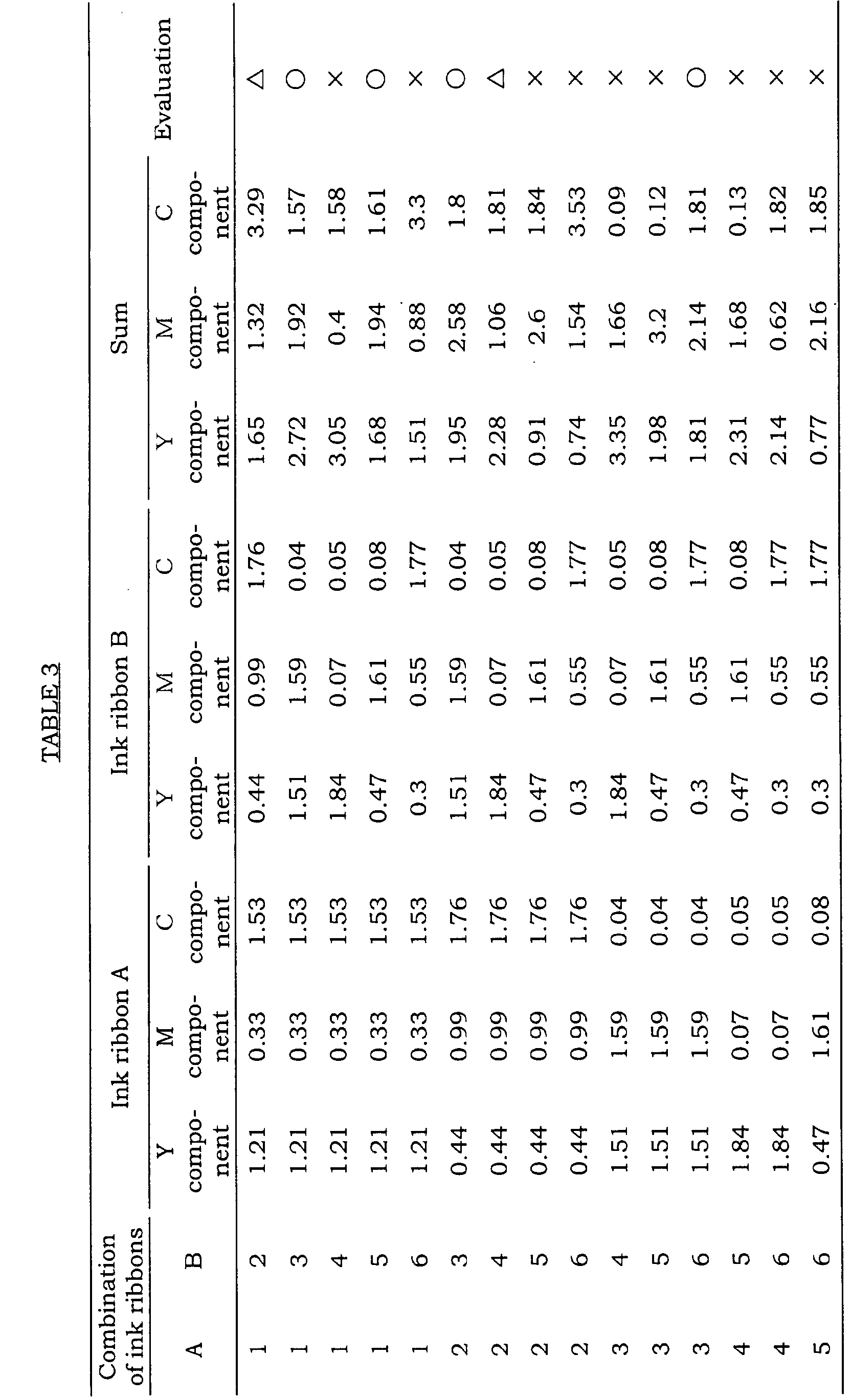
  • An image was formed under the following printing conditions by combining the selected image data and the combination of the ink ribbons A, B and the obtained image was observed with eyes and the natural degrees of the colors were evaluated according to the following criteria. The results are shown in Table 3.
  • Pseudo-full-color expression can be performed easily by thermal transfer using two color ink ribbons to save the time and the cost.
  • a method for forming an image by thermal transfer comprising forming a multi-color image using two chromatic color thermal transfer ink ribbons A and B, the thermal transfer ink ribbons A and B having respective chromatic colors which satisfy the following relations: Y A +Y B ⁇ 1.0 M A +M B ⁇ 1.0 C A +C B ⁇ 1.0 wherein Y A , M A , and C A are defined respectively as values obtained by color separation of the optical reflection density of the thermal transfer ink ribbon A into Y, M, and C components, and Y B , M B , and C B are defined respectively as values obtained by color separation of the optical reflection density of the thermal transfer ink ribbon B into Y, M, and C components.
Landscapes

  • Thermal Transfer Or Thermal Recording In General (AREA)
  • Impression-Transfer Materials And Handling Thereof (AREA)
  • Electronic Switches (AREA)

Abstract

A method for forming an image by thermal transfer: comprising forming a multi-color image using two chromatic color thermal transfer ink ribbons A and B, the thermal transfer ink ribbons A and B having respective chromatic colors which satisfy the following relations: YA + YB ≧ 1.0 MA + MB ≧ 1.0 CA + CB ≧ 1.0 wherein YA, MA, and CA are defined respectively as values obtained by color separation of the optical reflection density of the thermal transfer ink ribbon A into Y, M, and C components, and YB, MB, and CB are defined respectively as values obtained by color separation of the optical reflection density of the thermal transfer ink ribbon B into Y, M, and C components.

Description

The present invention relates to a method for forming a multi-color image by selectively and thermally transferring two chromatic color heat sensitive ink layers onto an image receptor by means of a thermal transfer printer such as a printer with a thermal head.
Conventionally, full-color expression by thermal transfer was performed by utilizing colors obtained by a subtractive color mixing wherein three colors of cyan (C), magenta (M) and yellow (Y), which are process colors, or four colors including these three colors and further black (BK) were superimposed.
Although a high-quality color image with colors close to natural colors can be obtained by this method, the method has a disadvantage that the image data for outputting the image tends to become immense. Further, upon outputting the image, it is required to superimpose the colors three or four times, and hence, the method is not necessarily satisfactory in terms of the time required to carry out the printing and the consumption of the ink ribbons.
Especially, depending on the type of images to be required, some images are not necessarily required to have a high-quality and a wide color reproductivity just like the above described image. For example, in the case of instruction manuals of appliances, diagrammatic figures of appliances, and the like, it tends to be desirable to obtain an image economically at a high speed rather than the color reproductivity.
To deal with the above described requirements, the present inventors tried to form a multi-color image by thermal transfer using only two color ink ribbons. However, the color expression ranges were narrow and natural color expression could not be performed even if two colors among cyan (C), magenta (M), yellow (Y), and black (BK) conventionally used for process colors were used in combination, and the combinations of these two colors were found practically useless although high speed could be achieved. Further, it was especially difficult to express excellent shadow parts (black parts) by the foregoing two color combinations, resulting in failure to obtain a sharp and high-quality image.
In view of the foregoing, it is an object of the present invention to provide a thermal transfer image formation method capable of easily performing pseudo-full-color expression using two color ink ribbons while suppressing the cost and saving the time.
This and other objects of the present invention will become apparent from the description hereinafter.
The present invention provides a method for forming an image by thermal transfer:
  • comprising forming a multi-color image using two chromatic color thermal transfer ink ribbons A and B,
  • the thermal transfer ink ribbons A and B having respective chromatic colors which satisfy the following relations: YA+YB ≧1.0 MA+MB ≧ 1.0 CA+CB ≧ 1.0
  • wherein YA, MA, and CA are defined respectively as values obtained by color separation of the optical reflection density of the thermal transfer ink ribbon A into Y, M, and C components, and YB, MB, and CB are defined respectively as values obtained by color separation of the optical reflection density of the thermal transfer ink ribbon B into Y, M, and C components.
    The present invention provides a method for performing a multi-color expression using two chromatic color thermal transfer ink ribbons, characterized by a method for forming an image by thermal transfer using two color thermal transfer ink ribbons A and B having respective chromatic colors which satisfy that the sum of the optical reflection density for each color component obtained by color-separating the reflection density of the color of the ink ribbon A into Y, M, C components and the optical reflection density for each color component obtained by color-separating the reflection density of the color of the ink ribbon B into Y, M, C components is 1.0 or higher for every color component, as described above.
    By superimposing two colors satisfying the above described specified relations, all of Y, M, C components, which are three primary colors, can exist in the resultant image. As a result, natural color expression with rich hue is made possible. Further, since the minimum value of the sum of the respective optical reflection density values of the ink ribbons A and B for each color component is 1.0 or higher, shadow parts (black parts) expressed by superimposing two colors are made clear and sharp images can be provided. More preferably, the minimum value of the sum of the respective optical reflection density values of the ink ribbons A and B for each color component is 1.5 or higher. That is, it is more preferable to use thermal transfer ink ribbons having the respective optical reflection densities satisfying the following relations: YA+YB ≧1.5 MA+MB ≧ 1.5 CA+CB ≧ 1.5.
    Further, the chromatic color of one ribbon A out of the thermal transfer ink ribbons to be employed for the present invention is preferable to satisfy that the density value of at least one color component among the optical reflection density values (YA, MA, and CA) for components Y, M, and C obtained by separating the optical reflection density of the ribbon A into the respective color components is 0.9 or lower, more preferably 0.5 or lower. Just like, the chromatic color of the other ribbon B out of the thermal transfer ink ribbons to be employed for the present invention is preferable to satisfy that the density value of at least one color component among the optical reflection density values (YB, MB, and CB) for components Y, M, and C obtained by separating the optical reflection density of the ribbon B into the respective color components is 0.9 or lower, more preferably 0.5 or lower. If the density value of at least one color component among the optical reflection density values (YA, MA, and CA) or (YB, MB, and CB) obtained by separating the reflection density of each of the thermal transfer ink ribbons A and B into the respective color components exceeds the foregoing range, the resultant images are inferior in the color clearness and expression as chromatic colors tends to be deteriorated.
    In the present invention, the optical reflection density values (YA, MA, and CA) and (YB, MB, and CB) of the respective components Y, M, and C for two chromatic color thermal transfer ink ribbons A, B are measured by employing Gratag Macbeth RD-918 (produced by Macbeth Co.). The filters used respectively have the spectral sensitivity characteristics of ISO status 1 and have peak wave wavelength of 432 nm for blue, 536 nm for green, and 624 nm for red. The optical reflection density measurement was directly carried out on the surface of the colored ink layers of the thermal transfer ink ribbons.
    As the two chromatic color thermal transfer ink ribbons A, B to be used for the method of the present invention, any can be employed without particular limitation on other elements so long as they satisfy the above described optical reflection density conditions.
    For example, a variety of materials used as supports for conventional thermal transfer ink ribbons can be employed as a support to be used for the above described ink ribbons. However, from the viewpoints of heat resistance, heat conduction and the cost, polyester films with a thickness of 1 to 6 µm are preferable and a poly (ethylene terephthalate) film (PET film) is especially preferable. It is desirable to provide a heat resistant lubricating layer on the rear side (the side with which a thermal head or the like is brought into a sliding contact) of the support.
    For the ink layer of the above described ink ribbons, a variety of materials usable for conventionally known thermally transferable inks can be used, including those which comprises a binder composed of mainly a wax material and/or a thermoplastic resin, and a coloring agent dispersed in the binder.
    Those usable as the above described wax materials are, for example, paraffin wax, microcrystalline wax, Fischer-Tropsch wax, polyethylene waxes with various molecular weights and their modified waxes, carnauba wax, and the like. These wax materials can be used solely or as a mixture of two or more of them.
    Those usable as the above described thermoplastic resins are, for example, one or more of polymers selected from olefin copolymers such as ethylene/vinyl acetate copolymer, polyamide resin, polyester resin, butyral resin; methacrylic acid esters such as methyl methacrylate, ethyl methacrylate, butyl methacrylate, hydroxyethyl methacrylate and the like, and methacrylic acid, acrylic acid esters such as methyl acrylate, ethyl acrylate, butyl acrylate and the like, and acrylic acid; natural rubber, petroleum resin, rosin resin, styrene resin, and the like. These resin materials may be used solely or as a mixture of two or more of them.
    Those usable as the above described coloring agents are a variety of known pigments and dyes, and examples are azo type, phthalocyanine type, quinacridone type, thioindigo type, anthraquinone type, and isoindoline type pigments. These coloring agents may be used solely or as a mixture of two or more of them in combination.
    Further, in order to secure a clear color, the content of a coloring agent per unit area for an ink layer is preferably 0.3 to 1.5 g/m2. If the content per unit area for the ink layer is less than 0.3 g/m2, the optical reflection density becomes insufficient and on the other hand, if higher than 1.5 g/m2, the color clearness tends to be deteriorated.
    Further, in order to enhance a deep color as a whole, it may be to add a pigment such as a black pigment, e.g. carbon black, or a pigment with high density such as phthalocyanine type pigment, or a variety of fillers with high light-shielding property such as titanium oxide, aluminum powder or the like to a primary pigment (pigment determining the hue of an ink) to the extent within which they do not deteriorate the subtractive color mixing of two colors. The amount of such an auxiliary component is preferably 0.1 to 20 % by weight, more preferably 0.1 to 10 % by weight to the primary pigment. If the amount of the auxiliary component is less than the foregoing ranges, it is difficult to provide the effect of improving the deep color and on the other hand, if higher than the foregoing ranges, color cleanness tends to be deteriorated.
    In order to control the adhesion property of the surface of an ink layer, a surface modifying agent such as a lubricant or a variety of fillers may be added.
    The ink layer is preferably thin from the viewpoint of the image reproductivity and the thickness thereof is preferably 0.2 to 3.0 µm.
    In an ink ribbon to be employed for the present invention, in order to improve the adhesion property of the surface of the ink layer, an adhesive layer composed mainly of a thermoplastic resin may be provided on the ink layer. As the thermoplastic resins, those exemplified for the ink layer may appropriately be selected.
    Further, in order to improve the releasability of the ink layer from the support, it is preferable to provide a thermally fusible release layer between the support and the ink layer. The release layer is composed mainly of a wax material and may contain a thermoplastic resin if required. As the wax materials, those exemplified for the ink layer may appropriately be selected. Examples of the thermoplastic resins are olefin copolymers such as ethylene/vinyl acetate copolymer, polyamide resin, polyester resin, natural rubber, petroleum resin, rosin resin, styrene resin, and the like. The thickness of the release is preferably within a range of 0.1 to 2.0 µm in terms of thermal transferability. If the thickness of the release layer is smaller than the foregoing range, the effect of improving the releasability becomes insufficient and on the other hand, if greater than the foregoing range, too much heat quantity is required to melt the release layer and the transferability tends to be deteriorated.
    The image formation method of the present invention using two chromatic color ink ribbons can be carried out as follows: An original image was image-processed to be color-separated into three color components; red, green, and blue. Among the optical reflection density values obtained by color separation of the optical reflection density of each ink ribbon to be used into Y component, M component, and C component, two components with higher values are selected. These two components selected in such a manner and the color separation data of the image to be employed for printing are correlated with each other as shown in Table 1. The color separation data of the image (one among red, green, and blue) to be employed for printing are determined for each ink ribbon using the correlation shown in Table 1. One color separation data of the image determined in such a manner and one of ink ribbons are used to form an image on a receptor by a thermal transfer printer and then the other color separation data of the image and the other ink ribbon are used to form an image on the former image. Two color separation data of the image to be employed for image formation can appropriately be determined depending upon the type of colors of the original image, the use purpose of the image to be formed, and the like.
    Two components with higher values selected among optical reflection density values obtained by separation of optical reflection density of each ink ribbon into Y component, M component, and C component Color separation data of image to be used for printing
    Y component, M component Red
    M component, C component Blue
    C component, Y component Green
    The present invention will be described in detail by way of Examples. It is to be understood that the present invention is not limited to the Examples, and various change and modifications may be made in the present invention without departing from the spirit and scope thereof.
    Manufacture of ink ribbon 1
    A PET film with 2.5 µm thickness and having a 0.2 µm-thick silicone resin-based heat resistant lubricating layer on the rear side was used as a support. The following coating liquid for a release layer was applied onto the front side of the support and dried to form a 0.7 µm-thick release layer.
    Coating liquid for release layer
    Component Parts by weight
    Paraffin wax (melting point: 75°C) 7.0
    Candelilla wax (melting point: 70°C) 3.0
    Toluene 90.0
    Total 100.0
    The following coating liquid for an ink layer was applied onto the foregoing release layer and dried to form a 1.5 µm-thick ink layer, yielding an ink ribbon 1.
    Coating liquid for ink layer
    Component Parts by weight
    Ethylene/vinyl acetate copolymer 5.0
    Terpene phenol resin (melting point: 120°C) 2.0
    Phthalocyanine Green 2.5
    Disazo Yellow 0.3
    Carbon black 0.2
    Dispersant 0.1
    Toluene 40.0
    Total 50.1
    Manufacture of ink ribbon 2
    An ink ribbon 2 was obtained in the same manner as that for the ink ribbon 1 except the following coating liquid was used to form a 1.5 µm-thick ink layer.
    Coating liquid for ink layer
    Component Parts by weight
    Ethylene/vinyl acetate copolymer 5.0
    Terpene phenol resin (melting point: 120°C) 2.0
    Indanthrene Blue 2.5
    Phthalocyanine Blue 0.5
    Carbon black 0.2
    Dispersant 0.1
    Toluene 40.0
    Total 50.3
    Manufacture of ink ribbon 3
    An ink ribbon 3 was obtained in the same manner as that for the ink ribbon 1 except the following coating liquid was used to form a 1.5 µm-thick ink layer.
    Coating liquid for ink layer
    Component Parts by weight
    Ethylene/vinyl acetate copolymer 5.0
    Terpene phenol resin (melting point: 120°C) 2.0
    Anthraquinonyl Red 3.0
    Carbon black 0.2
    Dispersant 0.1
    Toluene 40.0
    Total 50.3
    Manufacture of ink ribbon 4
    An ink ribbon 4 was obtained in the same manner as that for the ink ribbon 1 except the following coating liquid was used to form a 1.5 µm-thick ink layer.
    Coating solution for ink layer
    Component Parts by weight
    Ethylene/vinyl acetate copolymer 5.0
    Terpene phenol resin (melting point: 120°C) 2.0
    Disazo Yellow 3.0
    Dispersant 0.3
    Toluene 40.0
    Total 50.3
    Manufacture of ink ribbon 5
    An ink ribbon 5 was obtained in the same manner as that for the ink ribbon 1 except the following coating liquid was used to form a 1.5 µm-thick ink layer.
    Coating liquid for ink layer
    Component Parts by weight
    Ethylene/vinyl acetate copolymer 5.0
    Terpene phenol resin (melting point: 120°C) 2.0
    Carmine 6 B 3.0
    Dispersant 0.3
    Toluene 40.0
    Total 50.3
    Manufacture of ink ribbon 6
    An ink ribbon 6 was obtained in the same manner as that for the ink ribbon 1 except the following coating liquid was used to form a 1.5 µm-thick ink layer.
    Coating liquid for ink layer
    Component Parts by weight
    Ethylene/vinyl acetate copolymer 5.0
    Terpene phenol resin (melting point: 120°C) 2.0
    Phthalocyanine Blue 3.0
    Dispersant 0.3
    Toluene 40.0
    Total 50.3
    With respect to each of the obtained ink ribbons 1 to 6, the optical reflection density values of the respective Y, M, and C components were measured. The results are shown in Table 2.
    Optical reflection density
    Y component M component C component
    Ribbon 1 1.21 0.33 1.53
    Ribbon 2 0.44 0.99 1.76
    Ribbon 3 1.51 1.59 0.04
    Ribbon 4 1.84 0.07 0.05
    Ribbon 5 0.47 1.61 0.08
    Ribbon 6 0.30 0.55 1.77
    Evaluation method
    The image data of a full-color evaluation pattern (a fruit basket, ISO/DIS 12640 registered data) was subjected to a color separation processing into red, green, and blue. According to the correlation shown in Table 1, the image data to be used was selected (two among red, green, and blue were selected) based on the values of Y, M, C components of the optical reflection density of the ink ribbons A, B selected from the ink ribbons 1 to 6 shown in Table 2. An image was formed under the following printing conditions by combining the selected image data and the combination of the ink ribbons A, B and the obtained image was observed with eyes and the natural degrees of the colors were evaluated according to the following criteria. The results are shown in Table 3.
    Printing conditions:
  • Printer: a thermal printer (a testing apparatus)
  • Print head: 600 dots per inch (edge distance: 100 µm)
  • Printing speed: 24.5 cm/sec
  • Receptor: Super Mat Art paper (manufactured by Mitsubishi Paper Mills, Ltd.)
  • Evaluation criteria:
  • ○: Approximately natural colors are reproduced.
  • Δ: Natural expression to a certain extent is obtained.
  • ×: An image with almost a single color is obtained.
    Figure 00150001
  • As being made clear according to the results in Table 3, in the case where the sum of the respective optical reflection density values for each color component obtained by color separation of the respective optical reflection density of two color thermal transfer ink ribbons used into Y component, M component and C component were 1.0 or higher, an image with colors close to a full-color original image could be obtained.
    In addition to the materials and ingredients used in the Examples, other materials and ingredients can be used in Examples as set forth in the specification to obtain substantially the same results.
    Pseudo-full-color expression can be performed easily by thermal transfer using two color ink ribbons to save the time and the cost.
    A method for forming an image by thermal transfer: comprising forming a multi-color image using two chromatic color thermal transfer ink ribbons A and B, the thermal transfer ink ribbons A and B having respective chromatic colors which satisfy the following relations: YA+YB ≧1.0 MA+MB ≧ 1.0 CA+CB ≧ 1.0 wherein YA, MA, and CA are defined respectively as values obtained by color separation of the optical reflection density of the thermal transfer ink ribbon A into Y, M, and C components, and YB, MB, and CB are defined respectively as values obtained by color separation of the optical reflection density of the thermal transfer ink ribbon B into Y, M, and C components.

    Claims (2)

    1. A method for forming an image by thermal transfer:
      comprising forming a multi-color image using two chromatic color thermal transfer ink ribbons A and B,
      the thermal transfer ink ribbons A and B having respective chromatic colors which satisfy the following relations: YA+YB ≧ 1.0 MA+MB ≧ 1.0 CA+CB ≧ 1.0
      wherein YA, MA, and CA are defined respectively as values obtained by color separation of the optical reflection density of the thermal transfer ink ribbon A into Y, M, and C components, and YB, MB, and CB are defined respectively as values obtained by color separation of the optical reflection density of the thermal transfer ink ribbon B into Y, M, and C components.
    2. The method for forming an image by thermal transfer according to Claim 1, wherein at least one among the optical reflection density values YA, MA, and CA is 0.9 or lower, and at least one among the optical reflection density values YB, MB, and CB is 0.9 or lower.
    EP01115581A 2000-06-29 2001-06-28 Method for forming image by thermal transfer Withdrawn EP1170144A3 (en)

    Applications Claiming Priority (2)

    Application Number Priority Date Filing Date Title
    JP2000197024 2000-06-29
    JP2000197024A JP4581053B2 (en) 2000-06-29 2000-06-29 Thermal transfer image forming method

    Publications (2)

    Publication Number Publication Date
    EP1170144A2 true EP1170144A2 (en) 2002-01-09
    EP1170144A3 EP1170144A3 (en) 2002-10-02

    Family

    ID=18695413

    Family Applications (1)

    Application Number Title Priority Date Filing Date
    EP01115581A Withdrawn EP1170144A3 (en) 2000-06-29 2001-06-28 Method for forming image by thermal transfer

    Country Status (3)

    Country Link
    US (1) US6504560B2 (en)
    EP (1) EP1170144A3 (en)
    JP (1) JP4581053B2 (en)

    Families Citing this family (1)

    * Cited by examiner, † Cited by third party
    Publication number Priority date Publication date Assignee Title
    JP7243189B2 (en) * 2018-12-28 2023-03-22 凸版印刷株式会社 THERMAL TRANSFER PRINTER, INK RIBBON, CONTROLLER AND DATA PROCESSING METHOD

    Family Cites Families (8)

    * Cited by examiner, † Cited by third party
    Publication number Priority date Publication date Assignee Title
    JPS61154868A (en) * 1984-12-27 1986-07-14 Minolta Camera Co Ltd Thermal printer
    JPS62255189A (en) * 1986-04-30 1987-11-06 Dainippon Printing Co Ltd Thermal transfer sheet for forming color picture
    US4903048A (en) * 1988-11-28 1990-02-20 Xerox Corporation Simulated color imaging using only two different colorants/toners
    JPH05193166A (en) * 1992-01-22 1993-08-03 Mitsubishi Electric Corp Thermal transfer recorder
    JP3204820B2 (en) * 1993-10-21 2001-09-04 富士写真フイルム株式会社 Thermal transfer recording material and image forming method
    JPH07214853A (en) * 1994-02-02 1995-08-15 Casio Comput Co Ltd Ribbon cassette and thermal transfer printing apparatus using the same
    US6046118A (en) * 1996-08-02 2000-04-04 E. I. Du Pont De Nemours And Company Composite sheet material
    JP4080077B2 (en) * 1998-11-19 2008-04-23 フジコピアン株式会社 Method for forming metallic gloss image

    Also Published As

    Publication number Publication date
    US20020109769A1 (en) 2002-08-15
    US6504560B2 (en) 2003-01-07
    JP2002011898A (en) 2002-01-15
    JP4581053B2 (en) 2010-11-17
    EP1170144A3 (en) 2002-10-02

    Similar Documents

    Publication Publication Date Title
    EP0492356A1 (en) Ink ribbon for thermal transfer printer
    JPH08112970A (en) Thermal transfer recording material
    JPH07117359A (en) Thermal transfer recording material and image forming method
    US6633320B2 (en) Multi-gradation recording method and thermal transfer recording medium used in the method
    EP0673789B1 (en) Thermal transfer recording medium
    US6504560B2 (en) Method for forming image by thermal transfer
    JPH0885269A (en) Thermal transfer sheet
    US6623589B2 (en) Color thermal transfer recording medium
    JPH11208130A (en) Thermal transfer recording medium
    JP4368503B2 (en) Image forming method
    EP1033260B1 (en) Thermal transfer recording medium
    JPH08197861A (en) Thermal transfer sheet and manufacturing method thereof
    JPH11221972A (en) Thermal transfer sheet
    JP3114977B2 (en) Thermal transfer sheet
    JP3357961B2 (en) Thermal transfer sheet
    JPH10329435A (en) Thermal transfer recording medium
    JP4090545B2 (en) Thermal transfer image forming method
    JPH0930140A (en) Metallic glossy thermal transfer recording material, recording method and recorded matter using the same
    JP2971556B2 (en) Thermal transfer ink ribbon
    JP4168106B2 (en) Thermal transfer recording medium
    JP2000190644A (en) Transcription sheet
    JPH0930141A (en) Metallic glossy thermal transfer recording material, recording method and recorded matter using the same
    JPH07276833A (en) Thermal transfer sheet and thermal transfer method
    JP4143742B2 (en) Thermal transfer recording medium
    JPH03166991A (en) thermal transfer sheet

    Legal Events

    Date Code Title Description
    PUAI Public reference made under article 153(3) epc to a published international application that has entered the european phase

    Free format text: ORIGINAL CODE: 0009012

    AK Designated contracting states

    Kind code of ref document: A2

    Designated state(s): AT BE CH CY DE DK ES FI FR GB GR IE IT LI LU MC NL PT SE TR

    AX Request for extension of the european patent

    Free format text: AL;LT;LV;MK;RO;SI

    PUAL Search report despatched

    Free format text: ORIGINAL CODE: 0009013

    AK Designated contracting states

    Kind code of ref document: A3

    Designated state(s): AT BE CH CY DE DK ES FI FR GB GR IE IT LI LU MC NL PT SE TR

    AX Request for extension of the european patent

    Free format text: AL;LT;LV;MK;RO;SI

    AKX Designation fees paid

    Designated state(s): DE FR GB

    STAA Information on the status of an ep patent application or granted ep patent

    Free format text: STATUS: THE APPLICATION IS DEEMED TO BE WITHDRAWN

    18D Application deemed to be withdrawn

    Effective date: 20030403