EP1170137A2 - Image forming apparatus - Google Patents
Image forming apparatus Download PDFInfo
- Publication number
- EP1170137A2 EP1170137A2 EP01115724A EP01115724A EP1170137A2 EP 1170137 A2 EP1170137 A2 EP 1170137A2 EP 01115724 A EP01115724 A EP 01115724A EP 01115724 A EP01115724 A EP 01115724A EP 1170137 A2 EP1170137 A2 EP 1170137A2
- Authority
- EP
- European Patent Office
- Prior art keywords
- lens array
- image
- conjugate length
- mtfave
- tco
- Prior art date
- Legal status (The legal status is an assumption and is not a legal conclusion. Google has not performed a legal analysis and makes no representation as to the accuracy of the status listed.)
- Withdrawn
Links
Images



Classifications
-
- G—PHYSICS
- G02—OPTICS
- G02B—OPTICAL ELEMENTS, SYSTEMS OR APPARATUS
- G02B13/00—Optical objectives specially designed for the purposes specified below
- G02B13/24—Optical objectives specially designed for the purposes specified below for reproducing or copying at short object distances
-
- H—ELECTRICITY
- H04—ELECTRIC COMMUNICATION TECHNIQUE
- H04N—PICTORIAL COMMUNICATION, e.g. TELEVISION
- H04N1/00—Scanning, transmission or reproduction of documents or the like, e.g. facsimile transmission; Details thereof
- H04N1/024—Details of scanning heads ; Means for illuminating the original
- H04N1/028—Details of scanning heads ; Means for illuminating the original for picture information pick-up
- H04N1/03—Details of scanning heads ; Means for illuminating the original for picture information pick-up with photodetectors arranged in a substantially linear array
- H04N1/031—Details of scanning heads ; Means for illuminating the original for picture information pick-up with photodetectors arranged in a substantially linear array the photodetectors having a one-to-one and optically positive correspondence with the scanned picture elements, e.g. linear contact sensors
- H04N1/0311—Details of scanning heads ; Means for illuminating the original for picture information pick-up with photodetectors arranged in a substantially linear array the photodetectors having a one-to-one and optically positive correspondence with the scanned picture elements, e.g. linear contact sensors using an array of elements to project the scanned image elements onto the photodetectors
-
- B—PERFORMING OPERATIONS; TRANSPORTING
- B41—PRINTING; LINING MACHINES; TYPEWRITERS; STAMPS
- B41J—TYPEWRITERS; SELECTIVE PRINTING MECHANISMS, i.e. MECHANISMS PRINTING OTHERWISE THAN FROM A FORME; CORRECTION OF TYPOGRAPHICAL ERRORS
- B41J2/00—Typewriters or selective printing mechanisms characterised by the printing or marking process for which they are designed
- B41J2/435—Typewriters or selective printing mechanisms characterised by the printing or marking process for which they are designed characterised by selective application of radiation to a printing material or impression-transfer material
- B41J2/447—Typewriters or selective printing mechanisms characterised by the printing or marking process for which they are designed characterised by selective application of radiation to a printing material or impression-transfer material using arrays of radiation sources
- B41J2/45—Typewriters or selective printing mechanisms characterised by the printing or marking process for which they are designed characterised by selective application of radiation to a printing material or impression-transfer material using arrays of radiation sources using light-emitting diode [LED] or laser arrays
- B41J2/451—Special optical means therefor, e.g. lenses, mirrors, focusing means
-
- H—ELECTRICITY
- H04—ELECTRIC COMMUNICATION TECHNIQUE
- H04N—PICTORIAL COMMUNICATION, e.g. TELEVISION
- H04N1/00—Scanning, transmission or reproduction of documents or the like, e.g. facsimile transmission; Details thereof
- H04N1/024—Details of scanning heads ; Means for illuminating the original
- H04N1/028—Details of scanning heads ; Means for illuminating the original for picture information pick-up
- H04N1/03—Details of scanning heads ; Means for illuminating the original for picture information pick-up with photodetectors arranged in a substantially linear array
- H04N1/031—Details of scanning heads ; Means for illuminating the original for picture information pick-up with photodetectors arranged in a substantially linear array the photodetectors having a one-to-one and optically positive correspondence with the scanned picture elements, e.g. linear contact sensors
- H04N1/0311—Details of scanning heads ; Means for illuminating the original for picture information pick-up with photodetectors arranged in a substantially linear array the photodetectors having a one-to-one and optically positive correspondence with the scanned picture elements, e.g. linear contact sensors using an array of elements to project the scanned image elements onto the photodetectors
- H04N1/0312—Details of scanning heads ; Means for illuminating the original for picture information pick-up with photodetectors arranged in a substantially linear array the photodetectors having a one-to-one and optically positive correspondence with the scanned picture elements, e.g. linear contact sensors using an array of elements to project the scanned image elements onto the photodetectors using an array of optical fibres or rod-lenses
-
- G—PHYSICS
- G02—OPTICS
- G02B—OPTICAL ELEMENTS, SYSTEMS OR APPARATUS
- G02B3/00—Simple or compound lenses
- G02B3/0006—Arrays
- G02B3/0037—Arrays characterized by the distribution or form of lenses
- G02B3/005—Arrays characterized by the distribution or form of lenses arranged along a single direction only, e.g. lenticular sheets
-
- G—PHYSICS
- G02—OPTICS
- G02B—OPTICAL ELEMENTS, SYSTEMS OR APPARATUS
- G02B3/00—Simple or compound lenses
- G02B3/0006—Arrays
- G02B3/0037—Arrays characterized by the distribution or form of lenses
- G02B3/0056—Arrays characterized by the distribution or form of lenses arranged along two different directions in a plane, e.g. honeycomb arrangement of lenses
-
- G—PHYSICS
- G02—OPTICS
- G02B—OPTICAL ELEMENTS, SYSTEMS OR APPARATUS
- G02B3/00—Simple or compound lenses
- G02B3/0087—Simple or compound lenses with index gradient
-
- H—ELECTRICITY
- H04—ELECTRIC COMMUNICATION TECHNIQUE
- H04N—PICTORIAL COMMUNICATION, e.g. TELEVISION
- H04N2201/00—Indexing scheme relating to scanning, transmission or reproduction of documents or the like, and to details thereof
- H04N2201/024—Indexing scheme relating to scanning, transmission or reproduction of documents or the like, and to details thereof deleted
- H04N2201/028—Indexing scheme relating to scanning, transmission or reproduction of documents or the like, and to details thereof deleted for picture information pick-up
- H04N2201/03—Indexing scheme relating to scanning, transmission or reproduction of documents or the like, and to details thereof deleted for picture information pick-up deleted
- H04N2201/031—Indexing scheme relating to scanning, transmission or reproduction of documents or the like, and to details thereof deleted for picture information pick-up deleted deleted
- H04N2201/03104—Integral pick-up heads, i.e. self-contained heads whose basic elements are a light source, a lens and a photodetector supported by a single-piece frame
- H04N2201/03108—Components of integral heads
- H04N2201/03112—Light source
-
- H—ELECTRICITY
- H04—ELECTRIC COMMUNICATION TECHNIQUE
- H04N—PICTORIAL COMMUNICATION, e.g. TELEVISION
- H04N2201/00—Indexing scheme relating to scanning, transmission or reproduction of documents or the like, and to details thereof
- H04N2201/024—Indexing scheme relating to scanning, transmission or reproduction of documents or the like, and to details thereof deleted
- H04N2201/028—Indexing scheme relating to scanning, transmission or reproduction of documents or the like, and to details thereof deleted for picture information pick-up
- H04N2201/03—Indexing scheme relating to scanning, transmission or reproduction of documents or the like, and to details thereof deleted for picture information pick-up deleted
- H04N2201/031—Indexing scheme relating to scanning, transmission or reproduction of documents or the like, and to details thereof deleted for picture information pick-up deleted deleted
- H04N2201/03104—Integral pick-up heads, i.e. self-contained heads whose basic elements are a light source, a lens and a photodetector supported by a single-piece frame
- H04N2201/03108—Components of integral heads
- H04N2201/03125—Light guide upstream of the scanned picture elements
-
- H—ELECTRICITY
- H04—ELECTRIC COMMUNICATION TECHNIQUE
- H04N—PICTORIAL COMMUNICATION, e.g. TELEVISION
- H04N2201/00—Indexing scheme relating to scanning, transmission or reproduction of documents or the like, and to details thereof
- H04N2201/024—Indexing scheme relating to scanning, transmission or reproduction of documents or the like, and to details thereof deleted
- H04N2201/028—Indexing scheme relating to scanning, transmission or reproduction of documents or the like, and to details thereof deleted for picture information pick-up
- H04N2201/03—Indexing scheme relating to scanning, transmission or reproduction of documents or the like, and to details thereof deleted for picture information pick-up deleted
- H04N2201/031—Indexing scheme relating to scanning, transmission or reproduction of documents or the like, and to details thereof deleted for picture information pick-up deleted deleted
- H04N2201/03104—Integral pick-up heads, i.e. self-contained heads whose basic elements are a light source, a lens and a photodetector supported by a single-piece frame
- H04N2201/03108—Components of integral heads
- H04N2201/03133—Window, i.e. a transparent member mounted in the frame
-
- H—ELECTRICITY
- H04—ELECTRIC COMMUNICATION TECHNIQUE
- H04N—PICTORIAL COMMUNICATION, e.g. TELEVISION
- H04N2201/00—Indexing scheme relating to scanning, transmission or reproduction of documents or the like, and to details thereof
- H04N2201/024—Indexing scheme relating to scanning, transmission or reproduction of documents or the like, and to details thereof deleted
- H04N2201/028—Indexing scheme relating to scanning, transmission or reproduction of documents or the like, and to details thereof deleted for picture information pick-up
- H04N2201/03—Indexing scheme relating to scanning, transmission or reproduction of documents or the like, and to details thereof deleted for picture information pick-up deleted
- H04N2201/031—Indexing scheme relating to scanning, transmission or reproduction of documents or the like, and to details thereof deleted for picture information pick-up deleted deleted
- H04N2201/03104—Integral pick-up heads, i.e. self-contained heads whose basic elements are a light source, a lens and a photodetector supported by a single-piece frame
- H04N2201/03108—Components of integral heads
- H04N2201/03141—Photodetector lens
-
- H—ELECTRICITY
- H04—ELECTRIC COMMUNICATION TECHNIQUE
- H04N—PICTORIAL COMMUNICATION, e.g. TELEVISION
- H04N2201/00—Indexing scheme relating to scanning, transmission or reproduction of documents or the like, and to details thereof
- H04N2201/024—Indexing scheme relating to scanning, transmission or reproduction of documents or the like, and to details thereof deleted
- H04N2201/028—Indexing scheme relating to scanning, transmission or reproduction of documents or the like, and to details thereof deleted for picture information pick-up
- H04N2201/03—Indexing scheme relating to scanning, transmission or reproduction of documents or the like, and to details thereof deleted for picture information pick-up deleted
- H04N2201/031—Indexing scheme relating to scanning, transmission or reproduction of documents or the like, and to details thereof deleted for picture information pick-up deleted deleted
- H04N2201/03104—Integral pick-up heads, i.e. self-contained heads whose basic elements are a light source, a lens and a photodetector supported by a single-piece frame
- H04N2201/03108—Components of integral heads
- H04N2201/03145—Photodetector
Definitions
- the present invention relates to an image forming apparatus using a rod lens array. More particularly, the invention relates to an image forming apparatus which secures uniformity of resolution while retaining its fundamental resolving power by disposing an object surface and an image surface at appropriate positions. This technique is useful when it is applied to a contact image sensor or an LED printer.
- a rod lens array 10 is constructed as an unit magnification imaging optical system in which a number of rod lenses 12 each having a refractive index distribution in the radial direction are arrayed such that their optical axes are arranged parallel to one another.
- the unit magnification imaging optical system is widely employed in facsimile equipment, copying machines, scanners, LED printers and the like.
- An object surface 14 is disposed facing one end faces of the rod lenses 12, and an image surface 16 is disposed facing the other end faces thereof.
- the object surface 14 is an original document surface and the image surface 16 is a sensorpixel contained surface.
- the object surface is a light emitting surface of the LED elements, and the image surface is a drum surface.
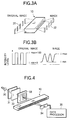
- the MTF indicates a fundamental resolving power of the rod lens array.
- Another approach, sometimes employed, is to adjust a distance TC between the object surface and the image surface (referred to as an object-image distance TC) so as to maximize the average value MTFave of the MTF.
- MTF (%) [(imax - imin)/(imax + imin)] x 100
- imax and imin are obtained in the following manner.
- a sensor receives the image 22.
- the relative maximum imax and the relative minimum imin of a light amount of the received image 22 are measured. It is evaluated that as the MTF is closer to 100%, an image formed by the optical system more accurately resembles an original image (the resolving power of the optical system is larger).
- the actual measurement is conducted using an optical system as shown in Fig. 4.
- a light source 30 such as a halogen lamp passes through a filter 31, a diffusion plate 32, and a rectangular test chart 33.
- a rectangular grating pattern is formed.
- the rod lens array 10 forms an image of the rectangular grating pattern.
- a CCD image sensor 34 receives the image and transforms it into a corresponding electrical signal.
- the rod lens array 10 is moved in the direction of a void arrow. Through the movement of the rod lens array, the image is inspected over the entire length thereof.
- a waveform of an output signal of the CCD image sensor 34 is output to a data processor 35.
- the data processor 35 appropriately processes the output wave form to have the relative maximum imax and the relative minimum imin of the waveform, and computes the MTF by using them.
- An average value of the MTF as computed in the lens array direction is the MTFave of the lens array.
- an image writing system can employ a defocused positional relationship in order to lessen the adverse influence of the variations in the light emissions of the LED elements.
- the resolution is distributed in the radial direction within a visual field. Consequently, an image superimposed by the rod lens array contains the resolution fluctuation in the longitudinal direction at a cycle of the lens radius (when the sensor pixel/LED element is aligned with the center position of the lens array) or at a cycle of the lens diameter (when the sensor pixel/LED element is not aligned with the center position of the lens array). If the rod lens array currently marketed is used at the resolution power of 600dip or higher, this resolution fluctuation is not negligible.
- an object of the present invention is to provide an image forming apparatus which secures uniformity of resolution in the lens array direction, while retaining the fundamental resolving power, and hence lessens the optical density non-uniformity to be negligible even in handling the half-tone image.
- an image forming apparatus which uses an unit magnification imaging rod lens array including a number of rod lenses each having a refractive index distribution in the radial direction and being arrayed such that their optical axes are arranged parallel to one another, and in which an object surface is disposed facing one end face of a rod lens array, while an image surface is disposed facing the other end face thereof, and a lens working distance of the rod lens array on the object side is substantially equal to that on the image side.
- the object-image distance Tco is set within +0.05mm ⁇ ⁇ TC ⁇ +0.15mm.
- the inventors of the present patent application studied such a phenomenon that when the half-tone image is used at high resolution, the optical density non-uniformity is noticeable, and reached the following conclusion.
- the following facts were found: 1) It is convenient to use a new parameter ⁇ MTF in evaluating the optical density non-uniformity, and 2) Generally, a conjugate length TC1 at which the average value MTFave of the MTF in the lens array direction (longitudinal direction) is maximized is not equal to a conjugate length TC2 at which ⁇ MTF is minimized.
- a direction in which the conjugate length TC2 at which ⁇ MTF is minimized is shifted with respect to the conjugate length TC1 at which the MTFave is maximized is determined by a refractive index distribution coefficient of the rod lens and the like (the direction : + direction in which the conjugate length increases or - direction in which it decreases). Accordingly, in the invention, it is important that the actual object-image distance Tco is set between the conjugate length TC1 at which the average value MTFave of the MTF of the rod lens array in the lens array direction is maximized and the conjugate length TC2 at which the ⁇ MTF is minimized. Further, in the invention, the lens working distance of the rod lens array on the object side is substantially equal to that on the image side.
- an optical shift quantity on each of the object side and the image side is ⁇ TC/2. Because of this, the decrease of the average value MTFave of the MTF is within a tolerable range. The uniformity of resolution in the lens array direction is secured while sustaining the high resolving power. Accordingly, the optical density non-uniformity is negligible even in handling the half-tone image.
- the MTF of a rod lens array having design specifications given below was calculated in the longitudinal direction (lens element array direction) for different higher order refractive index distribution coefficients.
- the calculation result is shown in Fig. 5.
- the design specifications of a basic rod lens array are:
- the difference between those lengths is shifted to the right or left (in the direction in which the object-image distance increases or decreases).
- the shift quantity ⁇ TC is set within a range +0.05mm ⁇ ⁇ TC ⁇ +0.15mm, the MTFave is high and ⁇ MTF is low. That is, good results are obtained.
- Fig. 6 is a graph showing variations of the average value MTFave of the MTF and ⁇ MTF' as measured by using the rod lens array specified on the basis of the simulation. In the measurement, the MTF full width profile at 12 lp/mm is actually measured. Variations of the average value MTFave of the MTF and ⁇ MTF' were obtained on the basis of the MTF full width profile.
- the present invention succeeds in providing an image forming apparatus with less variation of the resolution in the longitudinal direction without greatly decreasing the fundamental resolving power.
- the shift quantity ⁇ TC is set within a range of +0. 05mm ⁇ ⁇ TC ⁇ +0.15mm, a good characteristic where the average value MTFave and the ⁇ MTF are well balanced is obtained.
Landscapes
- Engineering & Computer Science (AREA)
- Signal Processing (AREA)
- Physics & Mathematics (AREA)
- Multimedia (AREA)
- Optics & Photonics (AREA)
- General Health & Medical Sciences (AREA)
- Toxicology (AREA)
- Health & Medical Sciences (AREA)
- General Physics & Mathematics (AREA)
- Facsimile Heads (AREA)
- Lenses (AREA)
- Printers Or Recording Devices Using Electromagnetic And Radiation Means (AREA)
- Light Sources And Details Of Projection-Printing Devices (AREA)
- Optical Fibers, Optical Fiber Cores, And Optical Fiber Bundles (AREA)
Abstract
Description
- where r : distance radially measured from the optical axis of the rod lens
- no : refractive index (= 1.625) on the optical axis of the rod lens
- g : refractive index distribution coefficient (= 0.8423) h4, h6, h8 : higher order refractive index distribution coefficient
| Case | h4 | h6 | h8 |
| A | 1.50 | -25 | 175 |
| B | 1.50 | -27 | 200 |
| C | 1.50 | -22 | 200 |
| D | 1.40 | -25 | 200 |
Claims (6)
- An image forming apparatus which uses an unit magnification imaging rod lens array including a number of rod lenses each having a refractive index distribution in the radial direction and being arrayed such that their optical axes are arranged parallel to one another, and in which an object surface is disposed facing one end face of the rod lens array, while an image surface is disposed facing the other end face thereof, and a lens working distance of the rod lens array on the object side is substantially equal to that on the image side,
wherein an actual object-image distance Tco is set between a conjugate length TC1 at which an average value MTFave of MTF of the rod lens array in the lens array direction is maximized and a conjugate length TC2 at which ΔMTF (= (MTFmax-MTFmin) /MTFave) is minimized. - The image forming apparatus according to claim 1, wherein said actual object-image distance Tco is equal to the conjugate length TC2 at which the ΔMTF is minimized and set, with respect to the conjugate length TC1 at which the MTFave is maximized, such that a shift quantity ΔTC (= |TCo - TC1|) is set within 0mm < ΔTC < +0.2mm.
- The image forming apparatus according to claim 2, wherein said actual object-image distance Tco is set, with respect to the conjugate length TC1 at which the MTFave is maximized, such that the shift quantity ΔTC (= |TCo - TC1|) is within +0.05mm < ΔTC < +0.15mm.
- An image forming apparatus which uses an unit magnification imaging rod lens array including a number of rod lenses each having a refractive index distribution in the radial direction and being arrayed such that their optical axes are arranged parallel to one another, and in which an object surface is disposed facing one end face of the rod lens array, while an image surface is disposed facing the other end face thereof, and a lens working distance of the rod lens array on the object side is substantially equal to that on the image side,
wherein an actual object-image distance Tco is equal to a conjugate length TC2 at which ΔMTF (= (MTFmax - MTFmin)/MTFave) is minimized and set, with respect to a conjugate length TC1 at which the MTFave is maximized, such that a shift quantity ΔTC (= |TCo - TC1|) is set within 0mm < ΔTC < +0.2mm. - The image forming apparatus according to claim 4, wherein said actual object-image distance TCo is set, with respect to the conjugate length TC1 at which the MTFave is maximized, such that the shift quantity ΔTC (= |TCo - TC1|) is within +0.05mm < ΔTC < +0.15mm.
- An image forming apparatus comprising:a rod lens array in which gradient index rod lenses are arrayed so that their optical axes are parallel to one another, the rod lens array having a characteristic of defining a first conjugate length TC1 at which an average value MTFave of MTF in the lens array direction is maximized and a second conjugate length TC2 at which ΔMTF (= (MTFmax - MTFmin)/MTFave) is minimized;an object surface facing one end face of the rod lens array; andan image surface facing the other end face of the rod lens array, and being disposed so that:a distance TCo between the object surface and the image surface falls within a range between the first conjugate length TC1 and the second conjugate length TC2, orthe distance TCo is substantially equal to the second conjugate length TC2 and offset from the first conjugate length TC1 by a predetermined shift quantity ΔTC (= I TCo - TC1|) falling within a range of 0mm to +0.2mm.
Applications Claiming Priority (2)
| Application Number | Priority Date | Filing Date | Title |
|---|---|---|---|
| JP2000207380 | 2000-07-07 | ||
| JP2000207380A JP4132599B2 (en) | 2000-07-07 | 2000-07-07 | Image forming apparatus |
Publications (2)
| Publication Number | Publication Date |
|---|---|
| EP1170137A2 true EP1170137A2 (en) | 2002-01-09 |
| EP1170137A3 EP1170137A3 (en) | 2002-03-06 |
Family
ID=18704147
Family Applications (1)
| Application Number | Title | Priority Date | Filing Date |
|---|---|---|---|
| EP01115724A Withdrawn EP1170137A3 (en) | 2000-07-07 | 2001-07-06 | Image forming apparatus |
Country Status (5)
| Country | Link |
|---|---|
| US (1) | US6563104B2 (en) |
| EP (1) | EP1170137A3 (en) |
| JP (1) | JP4132599B2 (en) |
| KR (1) | KR20020005458A (en) |
| CN (1) | CN1189767C (en) |
Cited By (1)
| Publication number | Priority date | Publication date | Assignee | Title |
|---|---|---|---|---|
| JP2013120298A (en) * | 2011-12-07 | 2013-06-17 | V Technology Co Ltd | Focal length measuring instrument and method of microlens array |
Families Citing this family (13)
| Publication number | Priority date | Publication date | Assignee | Title |
|---|---|---|---|---|
| JPH1097612A (en) * | 1996-08-02 | 1998-04-14 | Canon Inc | Image reading device and image reading system |
| JP2002144626A (en) * | 2000-11-15 | 2002-05-22 | Ricoh Co Ltd | Optical print head and image forming apparatus |
| CN100427973C (en) * | 2003-01-29 | 2008-10-22 | 三菱丽阳株式会社 | Rod lens array manufacturing device and manufacturing method |
| CN100472235C (en) * | 2003-01-29 | 2009-03-25 | 三菱丽阳株式会社 | Cutting method and device for original plate of rod lens array |
| EP1654002B2 (en) * | 2003-08-07 | 2014-01-29 | Allergan, Inc. | Compositions for delivery of therapeutics into the eyes |
| CN100523907C (en) * | 2006-12-11 | 2009-08-05 | 环隆电气股份有限公司 | Light emitting module and alignment and assembly method thereof |
| CN101242471B (en) * | 2007-02-05 | 2010-07-21 | 环隆电气股份有限公司 | Optical module and its alignment and assembly method |
| CN101413646B (en) * | 2007-10-19 | 2010-09-22 | 环隆电气股份有限公司 | Multi-wavelength light-emitting module |
| WO2011027536A1 (en) | 2009-09-01 | 2011-03-10 | オリンパス株式会社 | Optical device, image capturing device using same, and image capturing system |
| JP5569098B2 (en) * | 2010-03-30 | 2014-08-13 | 凸版印刷株式会社 | Outlet stopper for bag-like container |
| CN101950039B (en) * | 2010-08-24 | 2015-02-25 | 威海华菱光电有限公司 | Rod-shaped lens array and image reading device therefrom |
| JP2013186195A (en) * | 2012-03-06 | 2013-09-19 | Toshiba Tec Corp | Image forming apparatus, and lens array and manufacturing method of the same |
| JP6407811B2 (en) * | 2015-07-08 | 2018-10-17 | 富士フイルム株式会社 | Imaging apparatus and method |
Family Cites Families (16)
| Publication number | Priority date | Publication date | Assignee | Title |
|---|---|---|---|---|
| DE3438949C2 (en) * | 1983-10-25 | 1994-03-10 | Canon Kk | Printing device |
| JPH01243004A (en) * | 1988-03-25 | 1989-09-27 | Toshiba Corp | Module for optical communication |
| JPH0296541A (en) | 1988-09-30 | 1990-04-09 | Toshiba Corp | Complex metal alkoxide, method for forming magnetic thin film and dielectric thin film |
| US5185166A (en) * | 1988-12-07 | 1993-02-09 | San-Ei Chemical Industries, Ltd. | Process for the production of milk mineral concentrate and drink containing minerals |
| JPH0834531B2 (en) * | 1989-09-19 | 1996-03-29 | 三菱電機株式会社 | Reader |
| JPH03295354A (en) * | 1990-04-13 | 1991-12-26 | Fuji Xerox Co Ltd | Picture reader |
| JP3029662B2 (en) * | 1990-11-05 | 2000-04-04 | 株式会社東芝 | Playback device |
| JPH05237860A (en) * | 1992-02-26 | 1993-09-17 | Sanai:Kk | Vacuum chamber separator |
| JPH05260249A (en) * | 1992-03-12 | 1993-10-08 | Mitsubishi Rayon Co Ltd | Picture read unit |
| JP3178623B2 (en) * | 1992-06-29 | 2001-06-25 | 沖電気工業株式会社 | Electrophotographic printer, LED array head, and method of adjusting electrophotographic printer |
| JP3296623B2 (en) * | 1993-05-11 | 2002-07-02 | 三洋電機株式会社 | Optical print head |
| JP2966705B2 (en) * | 1993-09-24 | 1999-10-25 | 沖電気工業株式会社 | Image reading / writing device |
| JP2854537B2 (en) * | 1995-03-29 | 1999-02-03 | 双葉電子工業株式会社 | Photosensitive recording device |
| JP3294972B2 (en) * | 1995-08-14 | 2002-06-24 | 株式会社沖データ | LED head and LED position adjustment method |
| JP3337413B2 (en) * | 1998-02-13 | 2002-10-21 | 日本板硝子株式会社 | Imaging optics |
| JP2001194585A (en) * | 2000-01-12 | 2001-07-19 | Nippon Sheet Glass Co Ltd | Imaging optics |
-
2000
- 2000-07-07 JP JP2000207380A patent/JP4132599B2/en not_active Expired - Lifetime
-
2001
- 2001-07-05 US US09/898,030 patent/US6563104B2/en not_active Expired - Lifetime
- 2001-07-06 CN CNB011202025A patent/CN1189767C/en not_active Expired - Lifetime
- 2001-07-06 KR KR1020010040195A patent/KR20020005458A/en not_active Withdrawn
- 2001-07-06 EP EP01115724A patent/EP1170137A3/en not_active Withdrawn
Cited By (1)
| Publication number | Priority date | Publication date | Assignee | Title |
|---|---|---|---|---|
| JP2013120298A (en) * | 2011-12-07 | 2013-06-17 | V Technology Co Ltd | Focal length measuring instrument and method of microlens array |
Also Published As
| Publication number | Publication date |
|---|---|
| CN1332381A (en) | 2002-01-23 |
| EP1170137A3 (en) | 2002-03-06 |
| KR20020005458A (en) | 2002-01-17 |
| JP2002027197A (en) | 2002-01-25 |
| CN1189767C (en) | 2005-02-16 |
| US6563104B2 (en) | 2003-05-13 |
| US20020036255A1 (en) | 2002-03-28 |
| JP4132599B2 (en) | 2008-08-13 |
Similar Documents
| Publication | Publication Date | Title |
|---|---|---|
| US6563104B2 (en) | Image forming apparatus | |
| JPWO2009011153A1 (en) | Image reading device | |
| JP2000221442A (en) | Imaging optics | |
| US20120140111A1 (en) | Adjusting method for a lens unit, lens unit and image reading apparatus | |
| JPWO2007040246A1 (en) | Image imaging optical system, image reading apparatus and image writing apparatus using image imaging optical system | |
| EP0898181A2 (en) | Rod lens array and life-size imaging optical apparatus using the same | |
| TW460712B (en) | Optical imaging system | |
| EP1146355A2 (en) | Rod lens array | |
| US6724537B2 (en) | Lens array for unity magnification imaging, and image reading apparatus using the same array | |
| EP0786814A1 (en) | Photosensor array with compensation for optical aberrations and illumination non-uniformity | |
| US5959783A (en) | Rod lens array and life-size imaging optical apparatus using the same | |
| CN116235082B (en) | Image reading device | |
| US9103963B2 (en) | Rod lens array and equal-magnification imaging optical apparatus using rod lens array | |
| EP4538684A1 (en) | Optical line sensor | |
| US8274716B2 (en) | Image reading apparatus and method of controlling the same | |
| EP1191358A2 (en) | Rod lens array for line scanning | |
| CN119384625A (en) | Optical device, image sensor, and method for manufacturing optical device | |
| EP1345063B1 (en) | Imaging optical system for scanning | |
| US6469837B2 (en) | Imaging optical apparatus | |
| JP2007148047A (en) | Image reading unit, image reading apparatus, and image forming apparatus | |
| JP7709901B2 (en) | Reading device, inspection device, reading system, and method for manufacturing reading device | |
| TWI913196B (en) | Optical linear sensor and surface inspection device | |
| CN107238917B (en) | Optical devices and image readers | |
| JP2002318302A (en) | Rod lens and rod lens array | |
| JP2023179945A (en) | optical line sensor |
Legal Events
| Date | Code | Title | Description |
|---|---|---|---|
| PUAI | Public reference made under article 153(3) epc to a published international application that has entered the european phase |
Free format text: ORIGINAL CODE: 0009012 |
|
| AK | Designated contracting states |
Kind code of ref document: A2 Designated state(s): BE DE NL Kind code of ref document: A2 Designated state(s): AT BE CH CY DE DK ES FI FR GB GR IE IT LI LU MC NL PT SE TR |
|
| AX | Request for extension of the european patent |
Free format text: AL;LT;LV;MK;RO;SI |
|
| PUAL | Search report despatched |
Free format text: ORIGINAL CODE: 0009013 |
|
| AK | Designated contracting states |
Kind code of ref document: A3 Designated state(s): AT BE CH CY DE DK ES FI FR GB GR IE IT LI LU MC NL PT SE TR |
|
| AX | Request for extension of the european patent |
Free format text: AL;LT;LV;MK;RO;SI |
|
| RIC1 | Information provided on ipc code assigned before grant |
Free format text: 7G 02B 3/00 A, 7B 41J 2/45 B, 7H 04N 1/031 B |
|
| 17P | Request for examination filed |
Effective date: 20020612 |
|
| AKX | Designation fees paid |
Free format text: BE DE NL |
|
| STAA | Information on the status of an ep patent application or granted ep patent |
Free format text: STATUS: THE APPLICATION HAS BEEN WITHDRAWN |
|
| 18W | Application withdrawn |
Effective date: 20040206 |