EP0898181A2 - Rod lens array and life-size imaging optical apparatus using the same - Google Patents
Rod lens array and life-size imaging optical apparatus using the same Download PDFInfo
- Publication number
- EP0898181A2 EP0898181A2 EP98115504A EP98115504A EP0898181A2 EP 0898181 A2 EP0898181 A2 EP 0898181A2 EP 98115504 A EP98115504 A EP 98115504A EP 98115504 A EP98115504 A EP 98115504A EP 0898181 A2 EP0898181 A2 EP 0898181A2
- Authority
- EP
- European Patent Office
- Prior art keywords
- rod lens
- distance
- rod
- lens
- lens array
- Prior art date
- Legal status (The legal status is an assumption and is not a legal conclusion. Google has not performed a legal analysis and makes no representation as to the accuracy of the status listed.)
- Withdrawn
Links
- 230000003287 optical effect Effects 0.000 title claims abstract description 55
- 238000003384 imaging method Methods 0.000 title claims abstract description 26
- 239000000758 substrate Substances 0.000 claims description 14
- 230000000737 periodic effect Effects 0.000 claims description 6
- 238000005259 measurement Methods 0.000 description 9
- 239000011521 glass Substances 0.000 description 8
- 238000001444 catalytic combustion detection Methods 0.000 description 4
- 238000004519 manufacturing process Methods 0.000 description 4
- 239000006059 cover glass Substances 0.000 description 3
- 238000013461 design Methods 0.000 description 3
- 238000000034 method Methods 0.000 description 3
- 230000015572 biosynthetic process Effects 0.000 description 2
- 230000000052 comparative effect Effects 0.000 description 2
- 238000005286 illumination Methods 0.000 description 2
- 239000004033 plastic Substances 0.000 description 2
- 229920003023 plastic Polymers 0.000 description 2
- 230000004304 visual acuity Effects 0.000 description 2
- FUJCRWPEOMXPAD-UHFFFAOYSA-N Li2O Inorganic materials [Li+].[Li+].[O-2] FUJCRWPEOMXPAD-UHFFFAOYSA-N 0.000 description 1
- 230000004075 alteration Effects 0.000 description 1
- 125000002091 cationic group Chemical group 0.000 description 1
- XUCJHNOBJLKZNU-UHFFFAOYSA-M dilithium;hydroxide Chemical compound [Li+].[Li+].[OH-] XUCJHNOBJLKZNU-UHFFFAOYSA-M 0.000 description 1
- 230000000694 effects Effects 0.000 description 1
- 238000005516 engineering process Methods 0.000 description 1
- 238000005342 ion exchange Methods 0.000 description 1
- 239000000463 material Substances 0.000 description 1
- 230000001012 protector Effects 0.000 description 1
- 238000012552 review Methods 0.000 description 1
- 238000012360 testing method Methods 0.000 description 1
Images


Classifications
-
- G—PHYSICS
- G02—OPTICS
- G02B—OPTICAL ELEMENTS, SYSTEMS OR APPARATUS
- G02B3/00—Simple or compound lenses
- G02B3/0087—Simple or compound lenses with index gradient
-
- G—PHYSICS
- G02—OPTICS
- G02B—OPTICAL ELEMENTS, SYSTEMS OR APPARATUS
- G02B3/00—Simple or compound lenses
- G02B3/0006—Arrays
- G02B3/0037—Arrays characterized by the distribution or form of lenses
- G02B3/005—Arrays characterized by the distribution or form of lenses arranged along a single direction only, e.g. lenticular sheets
Definitions
- the present invention relates to a life-size imaging rod lens array comprising a plurality of small-diameter rod lenses arranged in one row.
- the invention also relates to a life-size imaging optical apparatus which has the surface of a document and a sensor provided on opposite sides of the rod lens array such that the image on the surface of a document is read and transmitted to the sensor.
- the technology of the invention is useful when applied to the optics of facsimile and other optical machines.
- a common scanning apparatus is of a "contact" type that comprises illumination optics, a rod lens array as life-size imaging optics, a sensor, a cover glass (transparent substrate) and other parts mounted in a frame.
- the document is placed in contact with the surface of the cover glass and illuminated with light from the illumination optics.
- the illuminated image on the document passes through the rod lens array to be focused on the sensor, where it is converted to an electrical signal.
- the rod lens array is life-size imaging optics in which a plurality of rod lenses each having a refractive-index distribution in the radial direction are arranged, typically in one or two rows.
- the lens material of which the rod lens array is made is either glass or plastics.
- Glass rod lenses with a refractive-index distribution are manufactured by ion-exchange or thermal interdiffusion or a like method.
- the rod lenses in a commercial glass rod lens array have a minimum outside diameter of 0.6 mm.
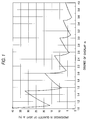
- a single rod lens forms a life-size image in a range defined by a circle with a radius of X 0 (i.e., the view radius) and the quantity of light which is maximal on the optical axis decrease with the increasing radial distance. Therefore, the distribution of the quantity of light along the length of the lens array experiences unevenness at a period which is equal to the distance between adjacent lenses.
- Fig. 1 shows how the unevenness in the quantity of light varies as a function of the degree of overlap m in a one-row rod lens array for a so-called "line scanning system" which utilizes light in an extremely narrow range near to the overall optical axis of the lens array.
- Fig. 1 The values of unevenness in the quantity of light that are shown in Fig. 1 are those which occur when the sensor is positioned accurately on the overall optical axis of the lens array.
- actual mass-produced scanning apparatus unavoidably suffer from a certain amount of transverse misalignment between the sensor and the overall axis of the lens array on account of dimensional errors in parts and assembling errors.
- each rod lens has an outside diameter of 0.6 mm or more
- the above-defined transverse misalignment is sufficiently smaller than the view radius X 0 that it can be ignored without any problem.
- the idea of reducing the rod lens diameter is recently under review in order to realize a compact scanning apparatus and if rod lenses with a diameter smaller than 0.5 mm are employed, the relative amount of transverse misalignment between the sensor and the overall axis of the lens array increases to potentially cause an unevenness in the quantity of light that exceeds the design value.
- An object, therefore, of the present invention is to provide a life-size imaging rod lens array which can be operated to produce a minimal amount of unevenness in the quantity of light even if a transverse misalignment occurs between the sensor and the overall axis of the lens array on account of the dimensional errors in parts and assembling errors resulting from the use of smaller-diameter rod lenses and which therefore contributes not only to the reduction in the size of a life-size imaging optical apparatus but also to the ease in its manufacture.
- Another object of the invention is to provide a life-size imaging optical apparatus using said rod lens array.
- the first aspect of the present invention is a life-size imaging rod lens array in which a plurality of rod lenses each having a refractive-index distribution in the radial direction are arranged in one row such that the optical axes are parallel to each other.
- the rod lens array is adapted to satisfy the following conditions:
- r 0 is equal to R.
- adjacent rod lenses are spaced apart by a certain distance for some reason associated with the process of assembling the lens array or the marginal area of each rod lens is sometimes rendered opaque in order to block the rays of light that will pass through that area where an undesirable index distribution will occur.
- the degree of overlap is defined in terms of R.
- the transverse misalignment between the sensor and the overall axis of the rod lens array is problematic if the rod lenses have a small diameter (R ⁇ 0.5 mm).
- R is specified to be at least 0.05 mm and smaller lens diameters are practically infeasible for various reasons such as one associated with manufacturing (e.g. extreme difficulty in handling). Another requirement is that r 0 be 0.5R or more but not greater than 1.0R. If r 0 is less than 0.5R, the brightness of the image will decrease to an undesirably low level.
- the rod lens array desirably has a ⁇ 0 of 0.05 or more.
- a rod lens having a ⁇ 0 in excess of 0.50 is difficult to fabricate by reason of the limits on the contents of index distributing components (e.g. Tl 2 O and Li 2 O to be used in glass lenses).
- the angle of aperture ⁇ 0 is specified to lie within the range 0.05 ⁇ n 0 ⁇ g ⁇ r 0 ⁇ 0.50 .
- the refractive index of each rod lens at the optical axis which is expressed by n 0 is preferably as large as possible since the angle of aperture ⁇ 0 increases with n 0 .
- the high contents of monovalent cationic components permit n 0 to take actual values within the range 1.40 ⁇ n 0 ⁇ 1.75.
- the unevenness is the quantity of light that occurs in the presence of transverse misalignment between the sensor and the overall axis of the lens array can be determined by using a mathematical expression for the distribution of the quantity of light within the view radius.
- the unevenness in the quantity of light that is tolerated by the scanning apparatus should generally be 15% or less, preferably 13% or less, more preferably 10% or less, at the design stage.
- a maximal amount of transverse misalignment is plotted in Fig. 4 against the degree of overlap m for three different cases where the unevenness in the quantity of light ⁇ i is not more than 15%, 13% and 10%.
- the transverse misalignment that occurs in the assembling process is on the order of 0.2 mm.
- the precision in assembling has to be further improved while securing the tolerable range of the transverse misalignment.
- the decrease in the quantity of light that occurs from transverse misalignment is desirably kept no more than 10%. If the amount of transverse misalignment divided by R exceeds 1.0, the average quantity of light drops to about 90% and below; hence, the amount of transverse misalignment must be held below 1.0R.
- the degree of overlap m should be within the range of 1.61 ⁇ m ⁇ 1.80 or 2.06 ⁇ m ⁇ 2.50, where the unevenness in the quantity of light is not more than 15% and the maximal amount of transverse misalignment is at least 1.0R or more.
- the unevenness in the quantity of light is often greater than the calculated value due to the variations in the performance and arrangement of individual lenses.
- the degree of overlap m should be assigned to lie between 1.62 (inclusive) and 1.72 (inclusive) or between 2.07 (inclusive) and 2.48 (inclusive), where the unevenness in the quantity of light is not more than 13%; a preferred range is 2.09 ⁇ m ⁇ 2.29 where the unevenness in the quantity of light is not more than 10%.
- a life-size imaging optical apparatus which uses a life-size imaging rod lens array in which a plurality of rod lenses each having a refractive-index distribution in the radial direction are arranged in two rows such that the optical axes are parallel to each other, with the surface of a document and a sensor being positioned on opposite sides of said lens array, said lens array satisfying the following conditions:
- One of the characteristic features of the rod lens array is that even if the distance L between the surface of a document and an end face of each proximal rod lens and the distance L between the sensor and an end face of each proximal rod lens, each distance being calculated as that of an air layer, are offset slightly from the lens working distance L 0 (i.e., to form a slightly defocused image), its resolving power will not deteriorate very much.
- L is between 0.8L 0 (inclusive) and 1.2L 0 (inclusive)
- the MTF value will not drop significantly but the unevenness in the quantity of light can be adjusted by varying the apparent degree of overlap m' through the adjustment of L.
- the thus set range is 1.61 ⁇ m' ⁇ 1.80 or 2.06 ⁇ m' ⁇ 2.50.
- a preferred range is 1.62 ⁇ m' ⁇ 1.72 or 2.07 ⁇ m' ⁇ 2.48, where the unevenness in the quantity of light is not more than 13% and a more preferred range is 2.09 ⁇ m' ⁇ 2.29 where the unevenness in the quantity of light is not more than 10%.
- n(r) 2 n 0 2 ⁇ 1-(g ⁇ r) 2 +h 4 ⁇ (g ⁇ r) 4 +h 6 ⁇ (g ⁇ r) 6 + ⁇ where h 4 and h 6 are coefficients of index distribution.
- h 4 influences the spherical aberration and the curvature of field and, hence, it has a substantial effect on the resolving power of the lens.
- h 4 is preferably between -0.5 (inclusive) and 1.5 (inclusive).
- the life-size imaging optical apparatus is to be used to read documents, it is usually equipped with a cover glass.
- a transparent substrate of which the observe surface provides the surface of a document is disposed in such a way that the surface of a document coincides with the front focal position of the lens array.
- the transparent substrate may be made of glass or plastics.
- an end face of the lens array is preferably placed in contact with the reverse surface of the transparent substrate.
- the transparent substrate serves not only as a protector of the individual rod lenses but also to keep a constant distance between the surface of a document and an end face of each proximal rod lens.
- the distance L between the surface of a document and an end face of each proximal rod lens, as well as the distance L between the sensor and an end face of each proximal rod lens, each distance being calculated as that of an air layer, have to be adjusted in accordance with the thickness of the transparent substrate and its refractive index. If the thickness of the transparent substrate is made equal to the distance L, one only need bring the lens surface of the rod lens array into contact with the reverse surface of the transparent substrate, whereupon the front focal distance of the lens array can always be rendered to coincide with the surface of the document (i.e., the obverse surface of the transparent substrate) without making any positional adjustment. As a result, the positioning of the front focal point of the lens array is obviated and the overall manufacturing process can be simplified.
- the unevenness in the quantity of light versus transverse misalignment was measured on various samples of a rod lens array in which a plurality of glass rod lenses were arranged in one row.
- Each rod lens had an outside diameter of 0.4 mm and its marginal portions were pigmented in black in order to block marginal rays of light that would not contribute to effective formation of a focused image.
- the effective lens radius r 0 was about 0.14 mm.
- the optical parameters of each rod lens array sample and their numerical values are shown in Tables 1 and 2.
- certain parameters of a rod lens array are specified in such a way that even if a transverse misalignment occurs between the sensor and the overall axis of the lens array due to the dimensional errors in parts and the assembling errors which accompany the adoption of smaller-diameter rod lenses, the unevenness in the quantity of light can be minimized to contribute to the realization of a compact life-size imaging optical apparatus and to greater ease in its manufacture.
Landscapes
- Physics & Mathematics (AREA)
- General Physics & Mathematics (AREA)
- Optics & Photonics (AREA)
- Lenses (AREA)
- Facsimile Heads (AREA)
- Optical Fibers, Optical Fiber Cores, And Optical Fiber Bundles (AREA)
Abstract
Description
- 2R:
- the distance between the optical axes of adjacent rod lenses;
- r3:
- the radius of the effective area of each rod lens that provides a lens action;
where
- r:
- the distance from the optical axis;
- n(r):
- the refractive index at distance r from the optical axis;
- n0:
- the refractive index at the optical axis;
- g:
- the coefficient of the refractive-index distribution;
- P:
- the periodic length of each rod lens as defined
by
- X0:
- the view radius of a single rod lens which is given
by
- L0:
- the lens working distance given by
- E0:
- the quantity of light on the optical axis;
- X:
- the distance from the optical axis; and
- E(X):
- the quantity of light at distance X from the optical axis.
- 2R:
- the distance between the optical axes of adjacent rod lenses;
- r0:
- the radius of the effective area of each rod lens that provides a lens action;
where
- r:
- the distance from the optical axis;
- n(r):
- the refractive index at distance r from the optical axis;
- n0:
- the refractive index at the optical axis;
- g:
- the coefficient of the refractive-index distribution;
- P:
- the periodic length of each rod lens as defined
by
- X':
- the view radius of a single rod lens which is given
by
- L0:
- the lens working distance given by
| Run | A | B | C | D | E |
| n0 | 1.59 | 1.59 | 1.59 | 1.59 | 1.59 |
| r0 (mm) | 0.141 | 0.141 | 0.141 | 0.142 | 0.144 |
| g (mm-1) | 1.008 | 0.990 | 0.995 | 0.994 | 0.989 |
| n0·g·r0 | 0.226 | 0.222 | 0.223 | 0.224 | 0.226 |
| P (mm) | 6.233 | 6.347 | 6.315 | 6.321 | 6.353 |
| Z0 (mm) | 3.613 | 3.608 | 3.565 | 3.563 | 3.565 |
| Z0/P | 0.580 | 0.568 | 0.565 | 0.564 | 0.561 |
| 2R (mm) | 0.4 | 0.4 | 0.4 | 0.4 | 0.4 |
| r0/R | 0.705 | 0.705 | 0.705 | 0.710 | 0.720 |
| L0 (mm) | 2.442 | 2.907 | 3.074 | 3.121 | 3.270 |
| X0 (mm) | 0.570 | 0.660 | 0.700 | 0.715 | 0.754 |
| L (mm) | L0 | L0 | L0 | L0 | L0 |
| Degree of overlap | 1.42 | 1.65 | 1.75 | 1.79 | 1.89 |
| MTF (%) | 82.13 | 80.76 | 78.74 | 78.58 | 75.33 |
| Run | F | G | H | I | J |
| n0 | 1.59 | 1.59 | 1.59 | 1.59 | 1.59 |
| r0 (mm) | 0.145 | 0.141 | 0.140 | 0.142 | 0.144 |
| g (mm-1) | 0.994 | 0.998 | 0.989 | 0.996 | 0.987 |
| n0·g·r0 | 0.229 | 0.224 | 0.220 | 0.225 | 0.226 |
| P (mm) | 6.321 | 6.296 | 6.353 | 6.308 | 6.366 |
| Z0 (mm) | 3.505 | 3.463 | 3.464 | 3.405 | 3.407 |
| Z0/P | 0.554 | 0.550 | 0.545 | 0.540 | 0.535 |
| 2R (mm) | 0.4 | 0.4 | 0.4 | 0.4 | 0.4 |
| r0/R | 0.725 | 0.705 | 0.700 | 0.710 | 0.720 |
| L0 (mm) | 3.660 | 3.975 | 4.443 | 5.030 | 5.740 |
| X0 (mm) | 0.851 | 0.900 | 0.988 | 1.140 | 1.305 |
| L (mm) | L0 | L0 | L0 | L0 | L0 |
| Degree of overlap | 2.13 | 2.25 | 2.47 | 2.85 | 3.26 |
| MTF (%) | 77.13 | 75.61 | 73.02 | 63.24 | 50.48 |
| Run | K | L | M | N | O | P | Q | R |
| n0 | 1.59 | 1.59 | 1.59 | 1.59 | 1.59 | 1.59 | 1.59 | 1.59 |
| r0 (mm) | 0.145 | 0.145 | 0.145 | 0.145 | 0.145 | 0.145 | 0.145 | 0.145 |
| g (mm-1) | 0.994 | 0.994 | 0.994 | 0.994 | 0.994 | 0.994 | 0.994 | 0.994 |
| n0·g·r0 | 0.229 | 0.229 | 0.229 | 0.229 | 0.229 | 0.229 | 0.229 | 0.229 |
| P (mm) | 6.321 | 6.321 | 6.321 | 6.321 | 6.321 | 6.321 | 6.321 | 6.321 |
| Z0 (mm) | 3.505 | 3.505 | 3.505 | 3.505 | 3.505 | 3.505 | 3.505 | 3.505 |
| Z0/P | 0.554 | 0.554 | 0.554 | 0.554 | 0.554 | 0.554 | 0.554 | 0.554 |
| 2R (mm) | 0.4 | 0.4 | 0.4 | 0.4 | 0.4 | 0.4 | 0.4 | 0.4 |
| r0/R | 0.725 | 0.725 | 0.725 | 0.725 | 0.725 | 0.725 | 0.725 | 0.725 |
| L0 (mm) | 3.660 | 3.660 | 3.660 | 3.660 | 3.660 | 3.660 | 3.660 | 3.660 |
| L (mm) | 2.648 | 2.848 | 3.048 | 3.248 | 3.448 | 3.848 | 4.248 | 4.448 |
| L/L0 | 0.724 | 0.778 | 0.833 | 0.887 | 0.942 | 1.05 | 1.161 | 1.215 |
| X' (mm) | 0.616 | 0.662 | 0.709 | 0.755 | 0.802 | 0.894 | 0.988 | 1.035 |
| Degree of overlap | 1.54 | 1.66 | 1.77 | 1.89 | 2.00 | 2.23 | 2.47 | 2.59 |
| MTF (%) | 46.11 | 58.22 | 68.86 | 75.04 | 76.88 | 76.69 | 67.36 | 56.24 |
Claims (7)
- A life-size imaging rod lens array comprising:a plurality of rod lenses each having a refractive-index distribution in the radial direction are arranged in one row such that the optical axes are parallel to each other, said rod lens array satisfying the following conditions:(1) the outside diameter of each rod lens is such that
- 2R:
- the distance between the optical axes of adjacent rod lenses;
- r0:
- the radius of the effective area of each rod lens that provides a lens action;
(2) when the refractive-index distribution of each rod lens is approximated by
where- r:
- the distance from the optical axis;
- n(r):
- the refractive index at distance r from the optical axis;
- n0:
- the refractive index at the optical axis;
- g:
- the coefficient of the refractive-index distribution;
(3) the length of each rod lens Z0 is such that- P:
- the periodic length of each rod lens as defined
by
(4) the degree of overlap m defined by- X0:
- the view radius of a single rod lens which is given
by
- A life-size imaging optical apparatus comprising:a life-size imaging rod lens array in which a plurality of rod lenses each having a refractive-index distribution in the radial direction are arranged in one row such that the optical axes are parallel to each other, with the surface of a document and a sensor being positioned on opposite sides of said lens array, said rod lens array satisfying the following conditions:wherein the distance L between the surface of a document and an end face of each proximal rod lens and the distance L between the sensor and an end face of each proximal rod lens, each distance being calculated as that of an air layer, both satisfy the following condition:(1) the outside diameter of each rod lens is such that
- 2R:
- the distance between the optical axes of adjacent rod lenses;
- r0:
- the radius of the effective area of each rod lens that
provides a lens action;
(2) when the refractive-index distribution of each rod lens is
approximated by
where r: the distance from the optical axis; - n(r):
- the refractive index at distance r from the optical axis;
- n0:
- the refractive index at the optical axis;
- g:
- the coefficient of the refractive-index distribution;
(3) the length of each rod lens Z0 is such that- P:
- the periodic length of each rod lens as defined
by
(4) the degree of overlap m defined by- X0:
- the view radius of a single rod lens which is given by X0 = -r0/cos(Z0π/P),
- L0:
- the lens working distance given by
- A life-size imaging optical apparatus which uses a life-size imaging rod lens array in which a plurality of rod lenses each having a refractive-index distribution in the radial direction are arranged in one row such that the optical axes are parallel to each other, with the surface of a document and a sensor being positioned on opposite sides of said lens array, said lens array satisfying the following conditions:(1) the outside diameter of each rod lens is such that
- 2R:
- the distance between the optical axes of adjacent rod lenses;
- r0:
- the radius of the effective area of each rod lens that provides a lens action;
(2) when the refractive-index distribution of each rod lens is approximated by
where- r:
- the distance from the optical axis;
- n(r):
- the refractive index at distance r from the optical axis;
- n0:
- the refractive index at the optical axis;
- g:
- the coefficient of the refractive-index distribution;
(3) the length of each rod lens Z0 is such that- P:
- the periodic length of each rod lens as defined
by
(4) the degree of apparent overlap m' defined by- X':
- the view radius of a single rod lens which is given by X' = L·n0·g·r0/sin(Z0π/P); and
(5) the distance L between the surface of a document and an end face of each proximal rod lens and the distance L between the sensor and an end face of each proximal rod lens, each distance being calculated as that of an air layer, are each such that- L0:
- the lens working distance given by
- The life-size imaging optical apparatus according to claim 2, wherein a transparent substrate of which the obverse surface provides the surface of a document is disposed in such a way that the surface of a document coincides with the front focal position of the lens array.
- The life-size imaging optical apparatus according to claim 3, wherein a transparent substrate of which the obverse surface provides the surface of a document is disposed in such a way that the surface of a document coincides with the front focal position of the lens array.
- The life-size imaging optical apparatus according to claim 4, wherein an end face of the lens array is in contact with the reverse surface of the transparent substrate.
- The life-size imaging optical apparatus according to claim 5, wherein an end face of the lens array is in contact with the reverse surface of the transparent substrate.
Applications Claiming Priority (3)
| Application Number | Priority Date | Filing Date | Title |
|---|---|---|---|
| JP23652097 | 1997-08-18 | ||
| JP236520/97 | 1997-08-18 | ||
| JP23652097A JP4132145B2 (en) | 1997-08-18 | 1997-08-18 | 1X imaging optical device |
Publications (2)
| Publication Number | Publication Date |
|---|---|
| EP0898181A2 true EP0898181A2 (en) | 1999-02-24 |
| EP0898181A3 EP0898181A3 (en) | 1999-09-22 |
Family
ID=17001925
Family Applications (1)
| Application Number | Title | Priority Date | Filing Date |
|---|---|---|---|
| EP98115504A Withdrawn EP0898181A3 (en) | 1997-08-18 | 1998-08-18 | Rod lens array and life-size imaging optical apparatus using the same |
Country Status (4)
| Country | Link |
|---|---|
| US (1) | US5978146A (en) |
| EP (1) | EP0898181A3 (en) |
| JP (1) | JP4132145B2 (en) |
| TW (1) | TW396278B (en) |
Cited By (2)
| Publication number | Priority date | Publication date | Assignee | Title |
|---|---|---|---|---|
| EP0926513A3 (en) * | 1997-12-24 | 1999-10-06 | Nippon Sheet Glass Co., Ltd. | Rod lens array for optical imaging system |
| EP1231486A1 (en) * | 2001-02-07 | 2002-08-14 | Nippon Sheet Glass Co., Ltd. | Rod lens array for optical imaging system |
Families Citing this family (14)
| Publication number | Priority date | Publication date | Assignee | Title |
|---|---|---|---|---|
| TW524995B (en) | 1999-10-27 | 2003-03-21 | Mitsubishi Rayon Co | Lens array, image sensor, and information processor and information processing system comprising the image sensor |
| JP2001174606A (en) | 1999-12-20 | 2001-06-29 | Nippon Sheet Glass Co Ltd | Image forming optical device |
| TW504588B (en) * | 2000-09-22 | 2002-10-01 | Nippon Sheet Glass Co Ltd | Array of rod lenses used in scanner |
| TW499571B (en) * | 2000-09-29 | 2002-08-21 | Nippon Sheet Glass Co Ltd | Rod lens array and a process for producing the same |
| JP4172621B2 (en) | 2001-04-02 | 2008-10-29 | 日本板硝子株式会社 | Manufacturing method of rod lens array |
| US7139404B2 (en) | 2001-08-10 | 2006-11-21 | Hear-Wear Technologies, Llc | BTE/CIC auditory device and modular connector system therefor |
| JP2003121608A (en) * | 2001-10-10 | 2003-04-23 | Nippon Sheet Glass Co Ltd | Lens array for unmagnification imaging, image reader using the same array, and portable electronic equipment using the same device |
| JP2004174771A (en) * | 2002-11-25 | 2004-06-24 | Kyocera Corp | Image forming device |
| JP4704069B2 (en) * | 2005-02-28 | 2011-06-15 | 富士フイルム株式会社 | Endoscope illumination optical system |
| JP4864509B2 (en) * | 2006-03-31 | 2012-02-01 | 株式会社沖データ | Lens array, exposure apparatus, and image forming apparatus |
| US9103963B2 (en) | 2012-12-20 | 2015-08-11 | Mitsubishi Rayon Co., Ltd. | Rod lens array and equal-magnification imaging optical apparatus using rod lens array |
| JP6162315B1 (en) | 2016-12-22 | 2017-07-12 | 日本板硝子株式会社 | Manufacturing method of image sensor unit |
| US20230258846A1 (en) * | 2020-06-25 | 2023-08-17 | Nippon Sheet Glass Company, Limited | Rod lens array, optical device, image sensor, printer, inspection apparatus, base glass composition for gradient-index rod lens, and method of manufacturing gradient-index rod lens |
| WO2024210091A1 (en) * | 2023-04-06 | 2024-10-10 | 日本板硝子株式会社 | Rod lens array, contact image sensor, reading device, image inspection device, and method for manufacturing rod lens array |
Family Cites Families (7)
| Publication number | Priority date | Publication date | Assignee | Title |
|---|---|---|---|---|
| JPS5121594B2 (en) * | 1971-12-25 | 1976-07-03 | ||
| US4349248A (en) * | 1980-04-23 | 1982-09-14 | Xerox Corporation | Gradient index lens array with improved exposure uniformity |
| US4844589A (en) * | 1984-07-17 | 1989-07-04 | Hoya Corporation | Lenses having plural contiguous refractive index distribution substrates and method of manufacture |
| JP2684227B2 (en) * | 1989-04-19 | 1997-12-03 | 三菱電機株式会社 | Image sensor |
| JP2815130B2 (en) * | 1992-11-04 | 1998-10-27 | キヤノン株式会社 | Lens array and contact image sensor using the same |
| US5450157A (en) * | 1993-12-06 | 1995-09-12 | Xerox Corporation | Imaging system using a gradient index lens array with improved depth of focus |
| US5568320A (en) * | 1994-11-30 | 1996-10-22 | Xerox Corporation | Multiple row lens array alignable with multiple row image bar |
-
1997
- 1997-08-18 JP JP23652097A patent/JP4132145B2/en not_active Expired - Fee Related
-
1998
- 1998-07-29 US US09/124,074 patent/US5978146A/en not_active Expired - Lifetime
- 1998-08-17 TW TW087113490A patent/TW396278B/en not_active IP Right Cessation
- 1998-08-18 EP EP98115504A patent/EP0898181A3/en not_active Withdrawn
Cited By (4)
| Publication number | Priority date | Publication date | Assignee | Title |
|---|---|---|---|---|
| EP0926513A3 (en) * | 1997-12-24 | 1999-10-06 | Nippon Sheet Glass Co., Ltd. | Rod lens array for optical imaging system |
| US6031668A (en) * | 1997-12-24 | 2000-02-29 | Nippon Sheet Glass Co., Ltd. | Optical imaging system |
| EP1231486A1 (en) * | 2001-02-07 | 2002-08-14 | Nippon Sheet Glass Co., Ltd. | Rod lens array for optical imaging system |
| US7012721B2 (en) | 2001-02-07 | 2006-03-14 | Nippon Sheet Glass Company Limited | Optical imaging system with rod lens array |
Also Published As
| Publication number | Publication date |
|---|---|
| JP4132145B2 (en) | 2008-08-13 |
| TW396278B (en) | 2000-07-01 |
| EP0898181A3 (en) | 1999-09-22 |
| US5978146A (en) | 1999-11-02 |
| JPH1164605A (en) | 1999-03-05 |
Similar Documents
| Publication | Publication Date | Title |
|---|---|---|
| US5978146A (en) | Rod lens array and life-size imaging optical apparatus using the same | |
| EP0461660B1 (en) | F-Theta lens and image forming apparatus using the same | |
| EP0827004B1 (en) | Corrected scanning optical apparatus | |
| US5291008A (en) | Optical assembly and apparatus employing same using an aspherical lens and an aperture stop | |
| US4553036A (en) | Information detecting apparatus | |
| EP2166743A1 (en) | Image-scanning device | |
| US5418356A (en) | Reading optical system | |
| US5959783A (en) | Rod lens array and life-size imaging optical apparatus using the same | |
| TW460712B (en) | Optical imaging system | |
| CN100520479C (en) | Image reading apparatus using image reading lens | |
| EP0786815A1 (en) | Photosensor array with compensation for optical aberrations and illumination nonuniformity | |
| US5731914A (en) | Zoom lens | |
| EP1170137A2 (en) | Image forming apparatus | |
| EP0926513A2 (en) | Rod lens array for optical imaging system | |
| US5329403A (en) | Image reading lens | |
| US6366412B1 (en) | Lens system for reading images and image reader | |
| US6320704B1 (en) | Image readout lens and image readout apparatus using the same | |
| EP0857991B1 (en) | Scanning optical system | |
| US6738164B1 (en) | Color image reading apparatus | |
| US6288850B1 (en) | Image readout lens and image readout apparatus | |
| JP3337413B2 (en) | Imaging optics | |
| US5886827A (en) | Microscope objective lens with separated lens groups | |
| US20020158274A1 (en) | Charge coupled device with multi-focus lengths | |
| US6999246B2 (en) | Image scanning lens and image scanning device that uses same | |
| US6178030B1 (en) | Light-scanning optical system having wobble-correcting function and light-scanning apparatus using the same |
Legal Events
| Date | Code | Title | Description |
|---|---|---|---|
| PUAI | Public reference made under article 153(3) epc to a published international application that has entered the european phase |
Free format text: ORIGINAL CODE: 0009012 |
|
| AK | Designated contracting states |
Kind code of ref document: A2 Designated state(s): DE FR GB |
|
| AX | Request for extension of the european patent |
Free format text: AL;LT;LV;MK;RO;SI |
|
| PUAL | Search report despatched |
Free format text: ORIGINAL CODE: 0009013 |
|
| AK | Designated contracting states |
Kind code of ref document: A3 Designated state(s): AT BE CH CY DE DK ES FI FR GB GR IE IT LI LU MC NL PT SE |
|
| AX | Request for extension of the european patent |
Free format text: AL;LT;LV;MK;RO;SI |
|
| RIC1 | Information provided on ipc code assigned before grant |
Free format text: 6G 02B 3/00 A, 6H 04N 1/031 B |
|
| 17P | Request for examination filed |
Effective date: 19991223 |
|
| AKX | Designation fees paid |
Free format text: DE FR GB |
|
| 17Q | First examination report despatched |
Effective date: 20040113 |
|
| STAA | Information on the status of an ep patent application or granted ep patent |
Free format text: STATUS: THE APPLICATION IS DEEMED TO BE WITHDRAWN |
|
| 18D | Application deemed to be withdrawn |
Effective date: 20040525 |