EP1170050A1 - Method for regenerating electrically conductive adsorbents charged with organic substances - Google Patents
Method for regenerating electrically conductive adsorbents charged with organic substances Download PDFInfo
- Publication number
- EP1170050A1 EP1170050A1 EP01115901A EP01115901A EP1170050A1 EP 1170050 A1 EP1170050 A1 EP 1170050A1 EP 01115901 A EP01115901 A EP 01115901A EP 01115901 A EP01115901 A EP 01115901A EP 1170050 A1 EP1170050 A1 EP 1170050A1
- Authority
- EP
- European Patent Office
- Prior art keywords
- adsorbent
- regeneration
- heating
- gas
- organic substances
- Prior art date
- Legal status (The legal status is an assumption and is not a legal conclusion. Google has not performed a legal analysis and makes no representation as to the accuracy of the status listed.)
- Ceased
Links
Images


Classifications
-
- B—PERFORMING OPERATIONS; TRANSPORTING
- B01—PHYSICAL OR CHEMICAL PROCESSES OR APPARATUS IN GENERAL
- B01J—CHEMICAL OR PHYSICAL PROCESSES, e.g. CATALYSIS OR COLLOID CHEMISTRY; THEIR RELEVANT APPARATUS
- B01J20/00—Solid sorbent compositions or filter aid compositions; Sorbents for chromatography; Processes for preparing, regenerating or reactivating thereof
- B01J20/30—Processes for preparing, regenerating, or reactivating
- B01J20/34—Regenerating or reactivating
- B01J20/3441—Regeneration or reactivation by electric current, ultrasound or irradiation, e.g. electromagnetic radiation such as X-rays, UV, light, microwaves
-
- B—PERFORMING OPERATIONS; TRANSPORTING
- B01—PHYSICAL OR CHEMICAL PROCESSES OR APPARATUS IN GENERAL
- B01D—SEPARATION
- B01D53/00—Separation of gases or vapours; Recovering vapours of volatile solvents from gases; Chemical or biological purification of waste gases, e.g. engine exhaust gases, smoke, fumes, flue gases, aerosols
- B01D53/02—Separation of gases or vapours; Recovering vapours of volatile solvents from gases; Chemical or biological purification of waste gases, e.g. engine exhaust gases, smoke, fumes, flue gases, aerosols by adsorption, e.g. preparative gas chromatography
- B01D53/04—Separation of gases or vapours; Recovering vapours of volatile solvents from gases; Chemical or biological purification of waste gases, e.g. engine exhaust gases, smoke, fumes, flue gases, aerosols by adsorption, e.g. preparative gas chromatography with stationary adsorbents
-
- B—PERFORMING OPERATIONS; TRANSPORTING
- B01—PHYSICAL OR CHEMICAL PROCESSES OR APPARATUS IN GENERAL
- B01D—SEPARATION
- B01D2253/00—Adsorbents used in seperation treatment of gases and vapours
- B01D2253/10—Inorganic adsorbents
- B01D2253/102—Carbon
-
- B—PERFORMING OPERATIONS; TRANSPORTING
- B01—PHYSICAL OR CHEMICAL PROCESSES OR APPARATUS IN GENERAL
- B01D—SEPARATION
- B01D2259/00—Type of treatment
- B01D2259/40—Further details for adsorption processes and devices
- B01D2259/40083—Regeneration of adsorbents in processes other than pressure or temperature swing adsorption
- B01D2259/40088—Regeneration of adsorbents in processes other than pressure or temperature swing adsorption by heating
- B01D2259/40096—Regeneration of adsorbents in processes other than pressure or temperature swing adsorption by heating by using electrical resistance heating
Definitions
- the invention relates to a process for the regeneration of organic Substances containing electrically conductive adsorbents, which are heated by the passage of electrical current.
- the front of the load moves during the loading process in the direction of flow through the adsorber. If the adsorbent at the end of the adsorber seen in the flow direction is far loaded that the clean gas concentration a predetermined Limit is reached, the loading process of this adsorber is ended and switched to another freshly regenerated adsorber.
- the aim is usually that regenerate loaded adsorbent.
- regeneration is not possible or not is economical. This is especially the case when the concentration of organic matter is very small, such as in the supply air for buildings or in the circulating air of air conditioning systems from Buildings. In these cases, the loaded adsorbent is disposed of and replaced with new one.
- the bound ones can organic substances from the adsorbent in the regeneration step again be removed by changing the equilibrium conditions become.
- This can be done, for example, by the adsorbent is heated and the adsorbed organic substances by a Purge gas stream are expelled from the adsorbent.
- This method is used, for example, for steam-regenerated and inert-gas regenerated Activated carbon adsorption systems applied.
- the purge gas also serves as a heating medium for the adsorbent. Heating of the adsorbent and desorption of the organic So substances are inextricably linked.
- the inert gas regeneration as a rule Nitrogen used as an inert gas is even more complex than that Steam regeneration, because here the nitrogen via the adsorber in the circuit and this very deep in the condensation step must be cooled so that the desorbed organic substances condense and the residual loading of the adsorbent at the end of the regeneration step is so low that the desired clean gas concentration can be adhered to in the subsequent loading step.
- An essential one Improvement can be achieved if the adsorbent is not indirectly through the purge gas, but directly through the passage of electric current is heated. In this case, because of Decoupling the processes of heating and purging the amount of purge gas can be significantly reduced and significantly higher enrichment factors can be achieved.
- a device for recovering organic solvents which consists of a ring-shaped, electrically heated fixed bed filled with activated carbon granules, which first adsorbs the solvent from the exhaust gas stream and then for desorption or regeneration with the Regeneration gas is applied.
- the outer and inner jacket of the annular fixed bed consists of a grid metal forming the electrodes.
- the innermost coal layer is only insufficiently regenerated and it is therefore not possible to achieve very low clean gas concentrations during the loading step, for example a few ⁇ g / m 3 , as are required, for example, in the supply air for clean rooms.
- the disadvantage is that a great deal of effort must be made to distribute the regeneration gas evenly over the filter surface. So is the regeneration gas velocity, based on the Filter area in the example above, a 1 m x 3 m nur filter only 0.01 m / s. At this flow rate, for example, five layers of activated carbon fiber a pressure loss of only 10 Pa, see above that when the regeneration gas hits the filter, the gas must be evenly distributed. For example, this can be achieved are through a system of manifolds with over the height and the cross section distributed numerous holes from which the Regeneration gas emerges in the free jet (Fig. 2).
- Filter frame modules With a large amount of air to be treated, i.e. a variety of Filter frame modules are therefore either a large number (3 x Number of filter frames) to install manifolds or the distance between a manifold and the filter must be very large can be selected (0.87 m), which makes the construction volume of the apparatus uneconomical increased.
- the disadvantage of this method is that the regulation the temperature of the activated carbon fabric, which also comes from safety Reasons of essential importance for the practical Use of the procedure is very difficult.
- the reason for this Problem lies among others in that the thermal conductivity and the heat capacity of activated carbon fiber fabric is very low, making conventional Methods of temperature measurement, such as with electrically insulated thermocouples, react only with a long delay and in addition the "measured value" has very strong errors, because it depends on how good the (accidental) mechanical contact is between thermocouple and tissue. Since the heating up time of the Tissue from room temperature to about 200 ° C, for example, only about one Minute and also the electrical resistance of activated carbon fabric has a negative temperature coefficient This procedure poses a great risk of overheating of the activated carbon tissue.
- the loading in the laboratory adsorber 1 took place in the direction shown, coming from the raw gas line 5 via the filter 2 to the clean gas line 4.
- Five layers of ACF were clamped in the filter frame.
- the supply and discharge lines 3 and 6 are closed during the loading phase.
- the loading concentration was chosen at about 40 mg / m 3 for the solvent toluene, the relative humidity of the raw gas being kept at 50% at a temperature of 23 ° C.
- the speed at the filter was 0.07 m wide and 0.21 m high, was 0.3 m / s.
- the tests were carried out up to a breakthrough concentration of 10% of the raw gas concentration (FIG. 5).
- the chosen breakthrough concentration was 4 mg / m 3 , which was reached after about 40 min.
- the air flow was carried out in opposite direction to adsorption, depending on the gas velocity either via the desorption tube 3 or the normal piping 4 the desorption gas is introduced was (see Figs. 6 and 7).
- the regeneration air was through the regeneration air line 6 dissipated. During the entire regeneration, the heating and desorbing / There is cooling, the pipe gas line 5 is always closed.
- the temperature during the desorption was measured using IR measurement without contact on the filter surface and with special prepared thermocouples between the filter layers.
- the regeneration gas velocity has practically no influence on the desorption quality, the consumption of electrical energy or the electrical connected load and on the clean gas quality in the subsequent loading phase if the number of desorption intervals remains unchanged.
- Regeneration gas velocity (cm / s) 5 10 20 Regeneration gas distributor Yes No No Number of desorption intervals 7 7 7 Electrical heating power (kW) 0.16 0.16 0.16 Energy input per desorption interval (kJ) 24 24 24 24 Maximum desorption gas concentration (g / m 3 ) 10.2 11.5 10.5 Raw gas concentration (mg / m 3 toluene) 40 40 40 Relative humidity (%) 50 50 50 Clean gas concentration at the beginning of the subsequent loading phase (mg / m3 toluene) 0.1 0.18 0.13 Service life up to the breakthrough concentration of 10% of the raw gas concentration (min) 44 39 40
Abstract
Description
Die Erfindung betrifft ein Verfahren zur Regenerierung von mit organischen Substanzen beladenen elektrisch leitfähigen Adsorbentien, die durch Durchleitung von elektrischem Strom aufgeheizt werden.The invention relates to a process for the regeneration of organic Substances containing electrically conductive adsorbents, which are heated by the passage of electrical current.
Verfahren zur Abscheidung von organischen gasförmigen Stoffen aus Abgasströmen durch Adsorption an Adsorbentien, insbesondere an Aktivkohle, werden seit vielen Jahren industriell eingesetzt, so zum Beispiel in Anlagen zur Lösemittelrückgewinnung. Als Aktivkohle werden dabei überwiegend Festbettgranulatschüttungen verwendet. Seltener wird faserförmige Aktivkohle in Form von Matten, wie zum Beispiel Vliesen, Geweben oder Gestricken, die zu Ringadsorbern gewickelt oder in Rahmenkonstruktionen eingespannt sind, eingesetzt. Der Gesamtprozeß der Abgasreinigung durch Adsorption erfolgt in der Regel in drei Hauptschritten: dem Beladeschritt, dem Regenerationsschritt und dem Kühlschritt. Beim Beladeschritt wird das Adsorbens vom zu reinigenden Abgas durchströmt und bindet bei diesem Vorgang die organischen Stoffe in seiner inneren Porenstruktur. Im Laufe des Beladevorganges wandert dabei die Front der Beladung in Strömungsrichtung durch den Adsorber. Wenn das Adsorbens am in Strömungsrichtung gesehenen Ende des Adsorbers so weit beladen ist, dass die Reingaskonzentration einen vorgegebenen Grenzwert erreicht, wird der Beladevorgang dieses Adsorbers beendet und auf einen anderen frisch regenerierten Adsorber umgeschaltet. Aus wirtschaftlichen Gründen wird in der Regel angestrebt, das beladene Adsorbens zu regenerieren. Allerdings sind auch zahlreiche Fälle bekannt, bei denen eine Regeneration nicht möglich oder nicht wirtschaftlich ist. Dies ist insbesondere dann der Fall, wenn die Konzentration der organischen Stoffe sehr klein ist, wie zum Beispiel in der Zuluft für Gebäude oder in der Kreislaufluft von Klimaanlagen von Gebäuden. In diesen Fällen wird das beladene Adsorbens entsorgt und durch neues ersetzt.Process for the separation of organic gaseous substances Exhaust gas flows through adsorption on adsorbents, in particular Activated carbon has been used industrially for many years, so for Example in systems for solvent recovery. As activated carbon fixed bed granulate fillings are mainly used. Fibrous activated carbon in the form of mats, such as Example nonwovens, woven fabrics or knitted fabrics that form ring adsorbers wrapped or clamped in frame structures. The overall process of exhaust gas purification takes place through adsorption usually in three main steps: the loading step, the regeneration step and the cooling step. In the loading step, this will be Flue gas to be cleaned flows through adsorbent and binds this process the organic matter in its inner pore structure. The front of the load moves during the loading process in the direction of flow through the adsorber. If the adsorbent at the end of the adsorber seen in the flow direction is far loaded that the clean gas concentration a predetermined Limit is reached, the loading process of this adsorber is ended and switched to another freshly regenerated adsorber. For economic reasons, the aim is usually that regenerate loaded adsorbent. However, there are also numerous Known cases where regeneration is not possible or not is economical. This is especially the case when the concentration of organic matter is very small, such as in the supply air for buildings or in the circulating air of air conditioning systems from Buildings. In these cases, the loaded adsorbent is disposed of and replaced with new one.
Da die Adsorption ein reversibler Prozeß ist, können die gebundenen organischen Stoffe vom Adsorbens im Regenerationsschritt wieder entfernt werden, indem die Gleichgewichtsbedingungen geändert werden. Dies kann beispielsweise dadurch erfolgen, dass das Adsorbens erhitzt wird und die adsorbierten organischen Stoffe durch einen Spülgasstrom vom Adsorbens ausgetrieben werden. Dieses Verfahren wird beispielsweise bei den wasserdampfregenerierten und inertgasregenerierten Aktivkohleadsorptionsanlagen angewendet. In beiden Fällen dient das Spülgas gleichzeitig als Heizmedium für das Adsorbens. Aufheizung des Adsorbens und Desorption der organischen Stoffe sind also untrennbar gekoppelt. Wegen dieser indirekten Aufheizung des beladenen Adsorbens mit dem Spülgas sind sehr große Volumenströme des Spülgases erforderlich. Im Falle der Regeneration mit Wasserdampf muß dieser nach Austritt aus dem Adsorber gemeinsam mit den vom Adsorbens desorbierten organischen Stoffen kondensiert werden. Das entstehende Kondensat muß dann anschließend in aufwendigen Prozessen, zum Beispiel durch Rektifikation, so aufgearbeitet werden, dass Wasser und organische Stoffe separiert werden. Die Inertgasregeneration, bei der in der Regel Stickstoff als Inertgas verwendet wird, ist noch aufwendiger als die Wasserdampfregeneration, weil hier der Stickstoff über den Adsorber im Kreislauf geführt wird und dieser im Kondensationsschritt sehr tief gekühlt werden muß, damit die desorbierten organischen Stoffe kondensieren und die Restbeladung des Adsorbens am Ende des Regenerationsschritts so niedrig ist, dass die gewünschte Reingaskonzentration im nachfolgenden Beladeschritt eingehalten werden kann.Since adsorption is a reversible process, the bound ones can organic substances from the adsorbent in the regeneration step again be removed by changing the equilibrium conditions become. This can be done, for example, by the adsorbent is heated and the adsorbed organic substances by a Purge gas stream are expelled from the adsorbent. This method is used, for example, for steam-regenerated and inert-gas regenerated Activated carbon adsorption systems applied. In both In some cases, the purge gas also serves as a heating medium for the adsorbent. Heating of the adsorbent and desorption of the organic So substances are inextricably linked. Because of this indirect heating of the loaded adsorbent with the purge gas are very large Volume flows of the purge gas required. In the case of regeneration with water vapor, this must come together after exiting the adsorber with the organic substances desorbed from the adsorbent be condensed. The resulting condensate must then in complex processes, for example by rectification, be processed so that water and organic matter be separated. The inert gas regeneration, as a rule Nitrogen used as an inert gas is even more complex than that Steam regeneration, because here the nitrogen via the adsorber in the circuit and this very deep in the condensation step must be cooled so that the desorbed organic substances condense and the residual loading of the adsorbent at the end of the regeneration step is so low that the desired clean gas concentration can be adhered to in the subsequent loading step.
Dadurch, dass die Aufheizung des Adsorbens durch das Inertgas wegen dessen geringer Wärmekapazität nur sehr langsam erfolgt und dass große Strömungsgeschwindigkeiten, die zwischen 0,1 und 0,5 m/s liegen, erforderlich sind, können mit diesem Verfahren Anreicherungsfaktoren (= maximale Regenerationsgaskonzentration/Rohgaskonzentration) von nur etwa 40 erreicht werden. Eine schon wesentliche Verbesserung kann erreicht werden, wenn das Adsorbens nicht indirekt durch das Spülgas, sondern direkt durch Durchleitung von elektrischem Strom aufgeheizt wird. In diesem Fall kann wegen der Entkoppelung der Vorgänge Aufheizen und Spülen die Spülgasmenge wesentlich reduziert werden und können wesentlich höhere Anreicherungsfaktoren erreicht werden.Because the adsorbent is heated by the inert gas whose low heat capacity is very slow and that large flow rates that are between 0.1 and 0.5 m / s are required, enrichment factors can be obtained with this method (= maximum regeneration gas concentration / raw gas concentration) of only about 40 can be achieved. An essential one Improvement can be achieved if the adsorbent is not indirectly through the purge gas, but directly through the passage of electric current is heated. In this case, because of Decoupling the processes of heating and purging the amount of purge gas can be significantly reduced and significantly higher enrichment factors can be achieved.
So ist aus der DE 195 13 376 A1 eine Vorrichtung zur Rückgewinnung von organischen Lösemitteln bekannt, die aus einem ringförmigen, mit Aktivkohlegranulat gefüllten, elektrisch aufheizbaren Festbett besteht, welches zur Adsorption des Lösemittels zunächst von dem Abgasstrom und anschließend zur Desorption bzw. Regenerierung mit dem Regeneriergas beaufschlagt wird. Bei dieser Vorrichtung besteht der äußere und innere Mantel des ringförmigen Festbettes aus einem die Elektroden bildenden Gittermetall. Mit diesem Verfahren können Anreicherungsfaktoren von 120 erreicht werden und damit die erforderlichen Spülgasvolumenströme auf 5 bis 10 % der Rohgasvolumenströme reduziert werden. Bei den dann bezogen auf die Anströmfläche des Kohlebetts sehr kleinen spezifischen Gasmengen kann eine für eine gute Regeneration erforderliche gleichmäßig Beaufschlagung der Kohle mit Spülgas nur erreicht werden, wenn diese zentral im Inneren des Adsorbers zum Beispiel durch ein Verteilerrohr mit zahlreichen feinen Bohrungen erfolgt. Nachteilig für die Beladestandzeit und die Qualität der Reingaskonzentrationen bei diesem Verfahren ist, dass der Regenerationsgasstrom selbst durch die Aktivkohle aufgeheizt wird und bei der Regenerierung von innen nach außen deshalb die Kohle in der innersten Kohleschicht eine wesentlich niedrigere Regenerationstemperatur erreicht als in der äußeren Schicht. Als Folge hiervon wird die innerste Kohleschicht nur unzureichend regeneriert und es können somit keine sehr niedrigen Reingaskonzentrationen beim Beladeschritt erreicht werden von zum Beispiel einigen µg/m3, wie sie beispielsweise bei der Zuluft für Reinsträume erforderlich sind.From DE 195 13 376 A1, a device for recovering organic solvents is known, which consists of a ring-shaped, electrically heated fixed bed filled with activated carbon granules, which first adsorbs the solvent from the exhaust gas stream and then for desorption or regeneration with the Regeneration gas is applied. In this device, the outer and inner jacket of the annular fixed bed consists of a grid metal forming the electrodes. With this process, enrichment factors of 120 can be achieved and the required purge gas volume flows reduced to 5 to 10% of the raw gas volume flows. With the specific gas quantities then very small in relation to the inflow surface of the coal bed, a uniform application of purging gas to the coal required for good regeneration can only be achieved if this takes place centrally in the interior of the adsorber, for example through a distributor pipe with numerous fine bores. A disadvantage of the loading time and the quality of the clean gas concentrations in this process is that the regeneration gas stream is itself heated by the activated carbon and therefore, when regenerating from the inside out, the coal in the innermost layer of coal reaches a much lower regeneration temperature than in the outer layer. As a result, the innermost coal layer is only insufficiently regenerated and it is therefore not possible to achieve very low clean gas concentrations during the loading step, for example a few µg / m 3 , as are required, for example, in the supply air for clean rooms.
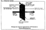
Aus der Patentschrift DE 41 04 513 C2 ist ein Adsorber bekannt, der ebenfalls direkt mit elektrischem Strom aufgeheizt wird, der dadurch gekennzeichnet ist, dass als adsorbierendes Material faserförmige Aktivkohle verwendet wird, die beispielsweise in Form von Matten vorliegt. Eine Ausführungsform eines solchen Adsorbers ist schematisch in Fig. 1 dargestellt.From the patent DE 41 04 513 C2 an adsorber is known which is also heated directly with electrical current, which thereby is characterized in that the adsorbent material is fibrous Activated carbon is used, for example in the form of mats is present. An embodiment of such an adsorber is schematic shown in Fig. 1.
Mehrere dieser Rahmen können zur Behandlung größerer Abluftmengen lufttechnisch und elektrisch in zahlreichen sinnvollen Anordnungen verschaltet werden. Wegen der sehr schnellen elektrischen Aufheizung der Gewebe, die in weniger als einer Minute erfolgen kann, können sehr hohe Anreicherungsfaktoren von bis zu 1500 erreicht werden, die vorteilhaft sind, wenn zum Beispiel Lösemittel zurückgewonnen werden sollen.Several of these frames can be used to treat larger amounts of exhaust air Ventilation and electrical in numerous sensible arrangements can be connected. Because of the very fast electrical heating the tissue that can be done in less than a minute can reach very high enrichment factors of up to 1500 which are advantageous when, for example, solvents are recovered should be.
Nachteilig ist, dass ein großer Aufwand getrieben werden muß, um das Regenerationsgas gleichmäßig über die Filterfläche zu verteilen. So beträgt die Regenerationsgasgeschwindigkeit, bezogen auf die Filterfläche im obigen Beispiel, eines 1 m x 3 m ―Filters nur 0,01 m/s. Bei dieser Strömungsgeschwindigkeit ergibt sich durch zum Beispiel fünf Lagen Aktivkohlefasergewebe ein Druckverlust von nur 10 Pa, so dass beim Auftreffen des Regenerationsgases auf das Filter das Gas schon gleichmäßig verteilt sein muß. Dies kann zum Beispiel erreicht werden durch ein System von Verteilerrohren mit über die Höhe und den Querschnitt verteilten zahlreichen Bohrungen, aus denen das Regenerationsgas im Freistrahl austritt (Fig. 2).The disadvantage is that a great deal of effort must be made to distribute the regeneration gas evenly over the filter surface. So is the regeneration gas velocity, based on the Filter area in the example above, a 1 m x 3 m nur filter only 0.01 m / s. At this flow rate, for example, five layers of activated carbon fiber a pressure loss of only 10 Pa, see above that when the regeneration gas hits the filter, the gas must be evenly distributed. For example, this can be achieved are through a system of manifolds with over the height and the cross section distributed numerous holes from which the Regeneration gas emerges in the free jet (Fig. 2).
Bei einer großen zu behandelnden Luftmenge, d.h. einer Vielzahl von Filterrahmenmodulen, sind deshalb entweder eine große Zahl (3 x Anzahl der Filterrahmen) Verteilerrohre zu installieren oder der Abstand zwischen einem Verteilerrohr und dem Filter muß sehr groß gewählt werden (0,87 m), was das Bauvolumen der Apparate unwirtschaftlich vergrößert.With a large amount of air to be treated, i.e. a variety of Filter frame modules are therefore either a large number (3 x Number of filter frames) to install manifolds or the distance between a manifold and the filter must be very large can be selected (0.87 m), which makes the construction volume of the apparatus uneconomical increased.
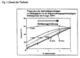
Weiterhin ist nachteilig, dass auch bei diesem Verfahren der elektrischen Regeneration die Desorptionsgasaufheizung durch Wärmeübertrag vom elektrisch aufgeheizten Gewebe auf die Luft stattfindet, mit den oben beschriebenen negativen Folgen auf die Wirksamkeit des Abluftreinigungsverfahrens durch Ausbildung eines Temperaturgradienten. Beim Einsatz von Aktivkohlefasergewebe wirkt sich dies, wie Fig. 3 zeigt, wegen der geringen Mengen der eingesetzten Kohle noch wesentlich stärker aus als bei Granulatkohle, wo zur Behandlung der gleichen Abluftmengen die mehr als 100-fache Menge Aktivkohle eingesetzt wird. Folge dieses starken Temperaturgradienten ist, dass bei der Regeneration gerade die für die Feinreinigung der Abluft wichtigen, in Regenerationsrichtung gesehen ersten Gewebelagen, nicht optimal regeneriert werden, was sich in einer Verkürzung der Beladestandzeiten und in einer Verschlechterung der erreichbaren Reingaskonzentrationen beim nachfolgenden Beladen bemerkbar macht. Dieser negative Effekt wirkt sich natürlich umso stärker aus, je höher die Regenerationsgasgeschwindigkeiten sind.Another disadvantage is that the electrical Regeneration of desorption gas heating by heat transfer from the electrically heated tissue to the air, with the negative effects on effectiveness described above the exhaust air purification process by forming a temperature gradient. When using activated carbon fiber fabric, this affects 3 shows, because of the small amounts of coal used even much stronger than with granular coal, where for treatment the same amount of exhaust air more than 100 times the amount of activated carbon is used. Follow this strong temperature gradient is that the regeneration is precisely that for the fine cleaning of the Exhaust air important, seen in the regeneration direction first layers of fabric, not be optimally regenerated, which results in a shortening the loading times and in a deterioration of the achievable Clean gas concentrations noticeable during subsequent loading makes. Of course, this negative effect is even more pronounced the higher the regeneration gas velocities.
Weiterhin ist nachteilig, dass, wie aus der nachfolgenden Tabelle
hervorgeht, bei höheren Desorptionsgasgeschwindigkeiten die erforderliche
elektrische Heizleistung drastisch mit zunehmender Desorptionsgasgeschwindigkeit
ansteigt. Dies hat zur Folge, dass aus wirtschaftlichen
Gründen bei elektrisch regenerierten Adsorbern aus Aktivkohlefasergewebe
die Regenerationsgasgeschwindigkeiten so gering
wie möglich gehalten werden, was wiederum die Installation eines
aufwendigen Regenerationsgasverteilersystems erforderlich
macht.
Schließlich ist bei diesem Verfahren nachteilig, dass die Regelung der Temperatur des Aktivkohlegewebes, die auch aus sicherheitstechnischen Gründen von essentieller Bedeutung für den praktischen Einsatz des Verfahrens ist, sehr schwierig ist. Der Grund für dieses Problem liegt u.a. darin, dass die Wärmeleitfähigkeit und die Wärmekapazität von Aktivkohlefasergewebe sehr gering ist, so dass herkömmliche Verfahren der Temperaturmessung, wie zum Beispiel mit elektrisch isolierten Thermoelementen, nur stark zeitverzögert reagieren und zudem der "Messwert" mit sehr starken Fehlern behaftet ist, weil er davon abhängt, wie gut der (zufällige) mechanische Kontakt zwischen Thermoelement und Gewebe ist. Da die Aufheizzeit des Gewebes von Raumtemperatur zum Beispiel auf 200°C nur etwa eine Minute beträgt und zudem der elektrische Widerstand von Aktivkohlegewebe einen negativen Temperaturkoeffizienten hat, besteht bei diesem Verfahren eine große Gefahr der Überhitzung des Aktivkohlegewebes. Finally, the disadvantage of this method is that the regulation the temperature of the activated carbon fabric, which also comes from safety Reasons of essential importance for the practical Use of the procedure is very difficult. The reason for this Problem lies among others in that the thermal conductivity and the heat capacity of activated carbon fiber fabric is very low, making conventional Methods of temperature measurement, such as with electrically insulated thermocouples, react only with a long delay and in addition the "measured value" has very strong errors, because it depends on how good the (accidental) mechanical contact is between thermocouple and tissue. Since the heating up time of the Tissue from room temperature to about 200 ° C, for example, only about one Minute and also the electrical resistance of activated carbon fabric has a negative temperature coefficient This procedure poses a great risk of overheating of the activated carbon tissue.
Bei beiden bekannten Verfahren der elektrischen Regeneration von Adsorbentien schließt sich der Kühlschritt an, bei dem das Adsorbens durch Durchleiten von Luft oder Inertgas auf die Temperatur gekühlt wird, wie sie für den nachfolgenden Beladeschritt erforderlich ist.In both known methods of electrical regeneration from Adsorbents are followed by the cooling step, in which the adsorbent cooled to temperature by passing air or inert gas through it as required for the subsequent loading step.
Aufgabe der Erfindung ist es deshalb, ein Verfahren der elektrischen Regenerierung von elektrisch leitfähigen Adsorbentien, insbesondere von Aktivkohlefasergeweben, zu finden, das einerseits die Vorzüge der elektrischen Regenerierung im Vergleich zu herkömmlichen Regenerationsverfahren, wie Inertgasregeneration und Wasserdampfregeneration, aufweist, wie
- sehr kurze Desorptionszeiten,
- sehr kurze Aufheizzeiten,
- sehr große Anreicherungsfaktoren bei der Regeneration,
- bei Bedarf Regenerationstemperaturen bis 300°C,
- bei faserförmigen Sorbentien extrem schnelle Kinetik des Stoffübergangs aus der Gas- in die Sorbensphase,
- gute Wirtschaftlichkeit, weil bei den Verfahren mit elektrischer
Regeneration nur die Aktivkohle und das Regenerationsgas und
nicht Rohrleitungen, Behälter und sonstige Anlagenteile aufgeheizt
werden,
aber nicht die Nachteile der herkömmlichen Verfahren zur elektrischen Regeneration von Adsorbentien aufweist, wie sie oben beschrieben wurden, also insbesondere: - auch große Desorptionsgasgeschwindigkeiten von wesentlich mehr als 2 cm/s ermöglicht, ohne dass der elektrische Anschlusswert zum Aufheizen des Adsorbens wesentlich größer ist als bei Desorptionsgasgeschwindigkeiten unter 1 cm/s. Dies ist insbesondere wünschenswert, wenn als Regenerationsgas Luft verwendet wird und diese Regenerationsluft nicht weiter gereinigt werden muß, wie zum Beispiel bei der Aufgabe, die Zuluft von Gebäuden von in der Außenluft vorhandenen gasförmigen Substanzen zu befreien,
- keine aufwendige Vorrichtung für die gleichmäßige Verteilung des Regenerationsgases über die Anströmfläche des Filters erfordert, so dass zum einen der apparative Aufwand für diese Verteilungseinrichtung entfällt und zum anderen der Platzbedarf derartiger Filter gegenüber der herkömmlichen Bauweise wesentlich reduziert wird,
- das Regenerationsverfahren intrinsisch sicher gegen Überhitzung oder Brand der Aktivkohlefaser ist, d.h. keine Temperaturregelung der elektrischen Leistung erforderlich ist.
- very short desorption times,
- very short heating times,
- very large enrichment factors during regeneration,
- if necessary regeneration temperatures up to 300 ° C,
- in the case of fibrous sorbents, extremely rapid kinetics of the mass transfer from the gas to the sorbent phase,
- good economic efficiency, because in the processes with electrical regeneration only the activated carbon and the regeneration gas are heated up and not the pipes, containers and other system parts,
but does not have the disadvantages of the conventional methods for electrical regeneration of adsorbents as described above, in particular: - it also enables high desorption gas velocities of significantly more than 2 cm / s without the electrical connection value for heating the adsorbent being significantly greater than at desorption gas velocities below 1 cm / s. This is particularly desirable if air is used as the regeneration gas and this regeneration air does not have to be purified further, for example in the case of the task of removing gaseous substances present in the outside air from the supply air to buildings.
- does not require any complex device for the uniform distribution of the regeneration gas over the inflow surface of the filter, so that on the one hand the expenditure on equipment for this distribution device is eliminated and on the other hand the space requirement of such filters is significantly reduced compared to the conventional design,
- the regeneration process is intrinsically safe against overheating or fire of the activated carbon fiber, ie no temperature control of the electrical power is required.
Erfindungsgemäß wird diese Aufgabe gelöst durch ein Regenerationsverfahren
gemäß den Patentansprüchen 1 bis 7.According to the invention, this object is achieved by a regeneration process
according to
Dies soll anhand des folgenden Beispiels, das auf Messwerten einer Versuchsanlage beruht, und bei dem alle Kennzeichen des erfindungsgemäßen Verfahrens angewandt wurden, erläutert werden.This should be based on the following example, which is based on measured values of a Test facility is based, and in which all the characteristics of the invention Procedures were used to be explained.
In einer Laborversuchsanlage, die für Luftmengen von 0 bis 30 m3/h dimensioniert ist, wurden gemäß den nachfolgenden Darstellungen Versuche zur Adsorption und Desorption mit Intervalltaktung während der Desorption durchgeführt.In a laboratory test facility, which is dimensioned for air volumes from 0 to 30 m 3 / h, tests for adsorption and desorption with interval clocking were carried out during the desorption according to the following representations.
Es zeigen
- Fig. 4
- eine geschnittene Darstellung des erfindungsgemäßen Adsorbers,
- Fig. 5
- die damit erzielte Durchbruchkurve Toluol,
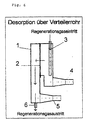
- Fig. 6 und Fig. 7
- schematische Darstellungen der Desorption über das Verteilerrohr und ohne das Verteilerrohr,
- Fig. 8 bis Fig. 11
- die zeitlichen Abläufe der getakteten Desorption.
- Fig. 4
- a sectional view of the adsorber according to the invention,
- Fig. 5
- the toluene breakthrough curve thus achieved,
- 6 and 7
- schematic representations of the desorption via the distributor pipe and without the distributor pipe,
- 8 to 11
- the temporal processes of the clocked desorption.
Wie in Fig. 4 dargestellt, erfolgte die Beladung im Laboradsorber 1 in
dargestellter Richtung von der Rohgasleitung 5 kommend über das
Filter 2 zur Reingasleitung 4. Dabei waren fünf Lagen ACF im Filterrahmen
eingespannt. Die zu- und abführenden Leitungen 3 und 6
sind während der Beladephase geschlossen. Die Beladekonzentration
wurde bei etwa 40 mg/m3 für das Lösemittel Toluol gewählt, wobei
die relative Feuchte des Rohgases bei einer Temperatur von 23°C
auf 50 % gehalten wurde.As shown in FIG. 4, the loading in the
Die Geschwindigkeit am Filter, dessen freie Filterfläche bei 0,07 m Breite und 0,21 m Höhe lag, betrug 0,3 m/s. Gefahren wurden die Versuche bis zu einer Durchbruchskonzentration von 10 % der Rohgaskonzentration (Fig. 5). Die gewählte Durchbruchskonzentration war 4 mg/m3, die nach etwa 40 min erreicht wurde.The speed at the filter, the free filter area of which was 0.07 m wide and 0.21 m high, was 0.3 m / s. The tests were carried out up to a breakthrough concentration of 10% of the raw gas concentration (FIG. 5). The chosen breakthrough concentration was 4 mg / m 3 , which was reached after about 40 min.
Bei der sich anschließenden Desorption erfolgte die Luftführung in
entgegengesetzter Richtung zur Adsorption, wobei in Abhängigkeit
von der Gasgeschwindigkeit entweder über das Desorptionsrohr 3
oder die normale Rohrleitungsführung 4 das Desorptionsgas eingeleitet
wurde (s. Fig. 6 und 7). Die Regenerationsluft wurde über die Regenerationsluftleitung
6 abgeführt. Während der gesamten Regeneration,
die aus den beiden Teilschritten Aufheizen und Desorbieren/
Kühlen besteht, ist die Rohrgasleitung 5 immer geschlossen.During the subsequent desorption, the air flow was carried out in
opposite direction to adsorption, depending on
the gas velocity either via the
Die Messung der Temperatur während der Desorption erfolgte mittels IR-Messung berührungslos auf der Filteroberfläche und mit speziell präparierten Thermoelementen zwischen den Filterlagen. The temperature during the desorption was measured using IR measurement without contact on the filter surface and with special prepared thermocouples between the filter layers.
Die getaktete Desorption wurde wie folgt (s. Fig. 8 bis 11) durchgeführt:
- Aufheizung des Filtermaterials durch direkte elektrische Beheizung
bei konstanter Leistungszufuhr über eine
Zeit von Nach Nach 0,5 Minuten Schließen der Ventile am Adsorber.- Aufheizung des Filtermaterials durch direkte elektrische Beheizung
bei konstanter Leistungszufuhr über eine
Zeit von
- Heating of the filter material by direct electrical heating with constant power supply over a period of 2.5 minutes. The valves on the adsorber were closed.
- After the electrical power supply has stopped for 2.5 minutes, the valves on the filter adsorber open for more than 0.5 minutes. During this time, the desorbed solvent and water are removed and the temperature at the filter is reduced. After closing the valves on the adsorber for 0.5 minutes.
- Heating of the filter material by direct electrical heating with constant power supply over a period of 2.5 minutes.
Durch diese zeitliche Taktung und Verfahrensführung erfolgte insgesamt jeweils sieben Mal für das Aufheizen und Durchströmung, danach wurde abgebrochen und es konnte ein weiterer Adsorptionsvorgang beginnen.This timing and process management resulted in a total seven times each for heating and flow, afterwards was canceled and another adsorption process was possible kick off.
Die bei den ersten beiden Intervallen erreichten geringeren Temperaturen während des Aufheizens am Filter sind bedingt durch die vorrangig stattfindende Desorption des adsorbierten Wassers auf der ACF. Ab dem dritten Intervall wurden dann die stationären Temperaturen für die entsprechende Leistungszufuhr und Zeit erreicht.The lower temperatures reached in the first two intervals while heating up the filter are due to the priority Desorption of the adsorbed water on the ACF. From the third interval onwards the steady-state temperatures became for the corresponding power supply and time reached.
Überraschend wurde nun festgestellt, dass mit dieser intervallmäßigen Regenerierung das Aktivkohlefasergewebe mit nur sieben Intervallen weitgehend desorbiert werden kann, obwohl während der eigentlichen Desorptionszeit ― die identisch ist mit der Kühlzeit ― keine elektrische Heizleistung zugeführt wurde, diese Zeit sehr kurz warzum Beispiel nur 30 Sekunden bei einer Regenerationsluftgeschwindigkeit von 20 cm/s ― sowie in dieser Zeit die Temperatur der Aktivkohlefasergewebe von ursprünglich 220°C auf ca. 40°C sank. Bei der nachfolgenden Beladephase wurde wieder die gleiche Standzeit erreicht; dies zeigt, dass ein stationärer Zustand vorlag, d.h. dass bei der Intervalldesorption die gleiche Menge Toluol desorbiert wurde, wie vorher in der Beladephase adsorbiert wurde.It has now surprisingly been found that with this interval Regeneration of the activated carbon fiber fabric with only seven intervals can be largely desorbed, although during the actual Desorption time - which is identical to the cooling time - none electrical heating power was supplied, this time was very short Example only 30 seconds at a regeneration air speed of 20 cm / s - and during this time the temperature of the activated carbon fiber fabrics dropped from originally 220 ° C to approx. 40 ° C. In the the same loading time was reached again in the subsequent loading phase; this shows that there was a steady state, i.e. that at the same amount of toluene was desorbed in the interval desorption, as previously adsorbed in the loading phase.
Überraschend, und für das vorgeschlagene Verfahren sehr vorteilhaft,
wurde weiterhin gefunden, dass bei dem erfindungsgemäßen
Regenerationsverfahren die Regenerationsgasgeschwindigkeit in weitem
Bereich praktisch keinen Einfluß auf die Desorptionsqualität, den
Verbrauch an elektrischer Energie bzw. die elektrische Anschlussleistung
und auf die Reingasqualität bei der nachfolgenden Beladephase
hat, wenn die Anzahl der Desorptionsintervalle unverändert bleibt.
Dies verdeutlicht die folgende Tabelle:
Claims (7)
dadurch gekennzeichnet, dass abwechselnd zeitlich nacheinander das Adsorbens durch Durchleitung von elektrischem Strom aufgeheizt wird, wobei kein Spülgasstrom durch das Adsorbens geführt wird und anschließend bei abgestelltem elektrischen Strom ein Spülgasstrom durch das Adsorbens geleitet wird, wodurch gleichzeitig die adsorbierten organischen Substanzen ausgetrieben werden und das Adsorbens gekühlt wird.Process for the regeneration of electrically conductive adsorbents loaded with organic substances, which are heated by the passage of electrical current,
characterized in that the adsorbent is alternately heated one after the other by passing electric current through, no purge gas flow being passed through the adsorbent and then, when the electric current is switched off, a purge gas flow is passed through the adsorbent, thereby simultaneously expelling the adsorbed organic substances and the adsorbent is cooled.
dadurch gekennzeichnet, dass die beiden Teilschritte Aufheizen und Desorbieren/Kühlen zeitlich nacheinander mehrmals wiederholt werden.Method according to claim 1,
characterized in that the two partial steps of heating and desorbing / cooling are repeated several times in succession.
dadurch gekennzeichnet, dass der Schritt Aufheizen für eine vorgegebene feste Zeit erfolgt.The method of claim 1 or 2,
characterized in that the heating step is carried out for a predetermined fixed time.
dadurch gekennzeichnet, dass die feste vorgegebene Heizzeit in der Weise berechnet wird, dass es die Zeit ist, die minimal benötigt wird, um bei einer gegebenen elektrischen Heizleistung das völlig unbeladene Adsorbens auf eine vorgegebene Maximaltemperatur aufzuheizen.Method according to claim 3,
characterized in that the fixed predetermined heating time is calculated in such a way that it is the minimum time required to heat the completely unloaded adsorbent to a predetermined maximum temperature at a given electrical heating power.
dadurch gekennzeichnet, dass die Leerrohrgeschwindigkeit durch das Adsorbens 0,1 bis 0,5 m/s beträgt.Method according to one of claims 1 to 4,
characterized in that the empty pipe speed through the adsorbent is 0.1 to 0.5 m / s.
dadurch gekennzeichnet, dass das Adsorbens aus faserförmiger Aktivkohle besteht, die in Form von Vliesen, Geweben oder Gestricken vorliegt.Method according to one of claims 1 to 5,
characterized in that the adsorbent consists of fibrous activated carbon, which is in the form of nonwovens, fabrics or knitted fabrics.
dadurch gekennzeichnet, dass die vorgegebenen Zeiten so gewählt werden, dass adsorbierte Gemische gemäß ihrer Flüchtigkeit nacheinander desorbiert und aufgefangen werden.Method according to one of claims 1 to 3,
characterized in that the predetermined times are chosen so that adsorbed mixtures are desorbed and collected one after the other according to their volatility.
Applications Claiming Priority (2)
| Application Number | Priority Date | Filing Date | Title |
|---|---|---|---|
| DE10032385 | 2000-07-06 | ||
| DE10032385A DE10032385B4 (en) | 2000-07-06 | 2000-07-06 | Process for the regeneration of electrically conductive adsorbents loaded with organic substances |
Publications (1)
| Publication Number | Publication Date |
|---|---|
| EP1170050A1 true EP1170050A1 (en) | 2002-01-09 |
Family
ID=7647687
Family Applications (1)
| Application Number | Title | Priority Date | Filing Date |
|---|---|---|---|
| EP01115901A Ceased EP1170050A1 (en) | 2000-07-06 | 2001-06-29 | Method for regenerating electrically conductive adsorbents charged with organic substances |
Country Status (8)
| Country | Link |
|---|---|
| US (1) | US6458186B1 (en) |
| EP (1) | EP1170050A1 (en) |
| JP (1) | JP2002102693A (en) |
| KR (1) | KR20020003518A (en) |
| CN (1) | CN1159094C (en) |
| DE (1) | DE10032385B4 (en) |
| SG (1) | SG94849A1 (en) |
| TW (1) | TWI278341B (en) |
Cited By (1)
| Publication number | Priority date | Publication date | Assignee | Title |
|---|---|---|---|---|
| WO2015036711A1 (en) | 2013-09-13 | 2015-03-19 | Arol Energy | Regenerative method for removing siloxane compounds from biogas |
Families Citing this family (10)
| Publication number | Priority date | Publication date | Assignee | Title |
|---|---|---|---|---|
| GB0106082D0 (en) * | 2001-03-13 | 2001-05-02 | Mat & Separations Tech Int Ltd | Method and equipment for removing volatile compounds from air |
| FI120637B (en) * | 2008-06-02 | 2009-12-31 | Environics Oy | Devices for concentrating and analyzing the components of a liquid medium and assay method |
| CN101450305B (en) * | 2008-12-10 | 2011-12-28 | 南华大学 | Direct-energization heating desorption regeneration device and method of radon-absorption active carbon |
| US20160303507A1 (en) * | 2015-04-17 | 2016-10-20 | Generon Igs, Inc. | Gas separation membrane module with integrated filter |
| KR102267445B1 (en) | 2016-02-15 | 2021-06-18 | 질리카 페어파렌스테크니크 게엠베하 | Device and method for treating a gas laden with pollutants |
| DE102017001114B4 (en) | 2016-02-15 | 2022-08-18 | Silica Verfahrenstechnik Gmbh | Device and method for treating a gas contaminated with pollutants |
| DE202016000949U1 (en) | 2016-02-15 | 2016-03-17 | Silica Verfahrenstechnik Gmbh | Apparatus for treating a contaminated gas |
| EP3488912B1 (en) * | 2017-11-28 | 2020-07-08 | Ammann Switzerland Ltd. | Gaseous stream treatment apparatus and plant for the production of bituminous macadams comprising said treatment apparatus |
| KR102124000B1 (en) | 2018-11-12 | 2020-06-17 | 한국에너지기술연구원 | Module type absorption system using absorption module unit |
| KR102158053B1 (en) | 2018-11-12 | 2020-09-28 | 한국에너지기술연구원 | Absorption apparatus using Active carbon fiber |
Citations (6)
| Publication number | Priority date | Publication date | Assignee | Title |
|---|---|---|---|---|
| JPS61287445A (en) * | 1985-06-13 | 1986-12-17 | Taiyo N P S Kk | Heat-regeneration method for adsorption apparatus |
| US4737164A (en) | 1984-07-06 | 1988-04-12 | Seinajoen Kylmakone A ja T Saikkonen Ky | Process for recovering contaminants from gases |
| DE4104513A1 (en) * | 1990-02-14 | 1991-08-29 | Chmiel Horst | Regeneration method for adsorbent carbon - by electrical heating of carbon material which has been removed from its locating unit and pressed into shapes or fibres |
| EP0532814A1 (en) | 1991-09-20 | 1993-03-24 | Guy Martin | Device for treating fluids with an adsorption structure of superposed and spaced layers and regeneration by joule effect |
| DE19513376A1 (en) | 1995-04-08 | 1996-10-10 | Gewerk Keramchemie | Recovery of organic solvents in exhaust air |
| US5628819A (en) * | 1995-09-28 | 1997-05-13 | Calgon Carbon Corporation | Method and apparatus for continuous adsorption of adsorbable contaminates and adsorber regeneration |
Family Cites Families (4)
| Publication number | Priority date | Publication date | Assignee | Title |
|---|---|---|---|---|
| US3608273A (en) * | 1969-01-15 | 1971-09-28 | Lowell Technological Inst Rese | Apparatus and process for desorption of filter beds by electric current |
| US5912423A (en) * | 1997-01-23 | 1999-06-15 | Calgon Carbon Corporation | Method and means for purifying air with a regenerable carbon cloth sorbent |
| US5827355A (en) * | 1997-01-31 | 1998-10-27 | Lockheed Martin Energy Research Corporation | Carbon fiber composite molecular sieve electrically regenerable air filter media |
| US6364936B1 (en) * | 2000-05-15 | 2002-04-02 | The Board Of Trustees Of The University Of Illinois | Selective sorption and desorption of gases with electrically heated activated carbon fiber cloth element |
-
2000
- 2000-07-06 DE DE10032385A patent/DE10032385B4/en not_active Expired - Fee Related
-
2001
- 2001-06-29 EP EP01115901A patent/EP1170050A1/en not_active Ceased
- 2001-06-29 TW TW090115917A patent/TWI278341B/en not_active IP Right Cessation
- 2001-07-04 KR KR1020010039724A patent/KR20020003518A/en not_active Application Discontinuation
- 2001-07-05 SG SG200104051A patent/SG94849A1/en unknown
- 2001-07-05 JP JP2001205219A patent/JP2002102693A/en active Pending
- 2001-07-05 US US09/899,578 patent/US6458186B1/en not_active Expired - Fee Related
- 2001-07-05 CN CNB011227192A patent/CN1159094C/en not_active Expired - Fee Related
Patent Citations (7)
| Publication number | Priority date | Publication date | Assignee | Title |
|---|---|---|---|---|
| US4737164A (en) | 1984-07-06 | 1988-04-12 | Seinajoen Kylmakone A ja T Saikkonen Ky | Process for recovering contaminants from gases |
| JPS61287445A (en) * | 1985-06-13 | 1986-12-17 | Taiyo N P S Kk | Heat-regeneration method for adsorption apparatus |
| DE4104513A1 (en) * | 1990-02-14 | 1991-08-29 | Chmiel Horst | Regeneration method for adsorbent carbon - by electrical heating of carbon material which has been removed from its locating unit and pressed into shapes or fibres |
| DE4104513C2 (en) | 1990-02-14 | 1996-11-28 | Chmiel Horst | Adsorber |
| EP0532814A1 (en) | 1991-09-20 | 1993-03-24 | Guy Martin | Device for treating fluids with an adsorption structure of superposed and spaced layers and regeneration by joule effect |
| DE19513376A1 (en) | 1995-04-08 | 1996-10-10 | Gewerk Keramchemie | Recovery of organic solvents in exhaust air |
| US5628819A (en) * | 1995-09-28 | 1997-05-13 | Calgon Carbon Corporation | Method and apparatus for continuous adsorption of adsorbable contaminates and adsorber regeneration |
Non-Patent Citations (1)
| Title |
|---|
| DATABASE WPI Section Ch Week 198705, Derwent World Patents Index; Class J01, AN 1987-032139, XP002179234 * |
Cited By (1)
| Publication number | Priority date | Publication date | Assignee | Title |
|---|---|---|---|---|
| WO2015036711A1 (en) | 2013-09-13 | 2015-03-19 | Arol Energy | Regenerative method for removing siloxane compounds from biogas |
Also Published As
| Publication number | Publication date |
|---|---|
| CN1159094C (en) | 2004-07-28 |
| DE10032385B4 (en) | 2005-07-14 |
| SG94849A1 (en) | 2003-03-18 |
| US6458186B1 (en) | 2002-10-01 |
| US20020088344A1 (en) | 2002-07-11 |
| CN1341482A (en) | 2002-03-27 |
| TWI278341B (en) | 2007-04-11 |
| JP2002102693A (en) | 2002-04-09 |
| KR20020003518A (en) | 2002-01-12 |
| DE10032385A1 (en) | 2002-01-24 |
Similar Documents
| Publication | Publication Date | Title |
|---|---|---|
| DE2534068C2 (en) | ||
| DE69910655T2 (en) | Adsorption process for solvent recovery | |
| DE69533426T2 (en) | Pressure and temperature change adsorption and temperature change adsorption | |
| DE2400492C2 (en) | Process for purifying an inert gas | |
| DE1963773A1 (en) | Process for the separation of oxygen from air | |
| DE3412007A1 (en) | METHOD FOR CLEANING WORKPIECES BY MEANS OF A LIQUID SOLVENT | |
| DE2917750A1 (en) | DEVICE FOR THE CONTINUOUS RECOVERY OF SOLVENT | |
| DE102017001114B4 (en) | Device and method for treating a gas contaminated with pollutants | |
| EP1170050A1 (en) | Method for regenerating electrically conductive adsorbents charged with organic substances | |
| DE102007020421A1 (en) | Process for the preparation of elemental sulfur doped carbonaceous adsorbents and methods for exhaust gas purification using such adsorbents | |
| EP3112010A1 (en) | Method for regenerating a voc adsorber and adsorbent device | |
| DE2645740A1 (en) | METHOD OF ELIMINATING THE LIQUID PHASE OF HYDROCARBONS OR DERIVATIVES FROM AN AEROSOL AND FILTER TO CARRY OUT THE PROCEDURE | |
| DE3139369C2 (en) | Adsorption filter with desorption device | |
| DE2901894A1 (en) | PROCEDURE FOR OPERATING AN ADSORBER SYSTEM AND ADSORBER SYSTEM FOR CARRYING OUT THIS PROCEDURE | |
| DE3303423C2 (en) | Process for the regeneration of the adsorber units in the low-water recovery of solvents from a gas stream and device for carrying out this process | |
| EP0381002B1 (en) | Process for the desorption of adsorbents | |
| EP3260185A1 (en) | Device and method for temperature swing adsorption for the purification of gases | |
| DE3123981A1 (en) | METHOD FOR REMOVING IMPURITIES FROM AN ACTIVE CARBON FILTER | |
| EP1358923B1 (en) | Particle or hybrid filter, in particular for the treatment of air to be introduced in a vehicle passenger compartment | |
| DE455798C (en) | Method and device for the recovery of the substances taken up by adsorbents | |
| DE102018006960A1 (en) | Method for operating a temperature swing adsorption plant and temperature swing adsorption plant | |
| EP0405119A1 (en) | Process and apparatus for separating metallic mercury from gas obtained by gasification or combustion of coal | |
| DE3320735C2 (en) | ||
| DE19513376A1 (en) | Recovery of organic solvents in exhaust air | |
| DE3827806C2 (en) |
Legal Events
| Date | Code | Title | Description |
|---|---|---|---|
| PUAI | Public reference made under article 153(3) epc to a published international application that has entered the european phase |
Free format text: ORIGINAL CODE: 0009012 |
|
| AK | Designated contracting states |
Kind code of ref document: A1 Designated state(s): AT BE CH CY DE DK ES FI FR GB GR IE IT LI LU MC NL PT SE TR |
|
| AX | Request for extension of the european patent |
Free format text: AL;LT;LV;MK;RO;SI |
|
| 17P | Request for examination filed |
Effective date: 20020529 |
|
| AKX | Designation fees paid |
Free format text: AT BE CH CY DE DK ES FI FR GB GR IE IT LI LU MC NL PT SE TR |
|
| 17Q | First examination report despatched |
Effective date: 20061221 |
|
| APBK | Appeal reference recorded |
Free format text: ORIGINAL CODE: EPIDOSNREFNE |
|
| APBN | Date of receipt of notice of appeal recorded |
Free format text: ORIGINAL CODE: EPIDOSNNOA2E |
|
| APBR | Date of receipt of statement of grounds of appeal recorded |
Free format text: ORIGINAL CODE: EPIDOSNNOA3E |
|
| APAF | Appeal reference modified |
Free format text: ORIGINAL CODE: EPIDOSCREFNE |
|
| APBT | Appeal procedure closed |
Free format text: ORIGINAL CODE: EPIDOSNNOA9E |
|
| STAA | Information on the status of an ep patent application or granted ep patent |
Free format text: STATUS: THE APPLICATION HAS BEEN REFUSED |
|
| 18R | Application refused |
Effective date: 20101117 |