EP1168675A2 - Gerät und Verfahren zur asymetrische Verwendung des Frequenzspektrums in einem drahtlosen Netz - Google Patents
Gerät und Verfahren zur asymetrische Verwendung des Frequenzspektrums in einem drahtlosen Netz Download PDFInfo
- Publication number
- EP1168675A2 EP1168675A2 EP01305585A EP01305585A EP1168675A2 EP 1168675 A2 EP1168675 A2 EP 1168675A2 EP 01305585 A EP01305585 A EP 01305585A EP 01305585 A EP01305585 A EP 01305585A EP 1168675 A2 EP1168675 A2 EP 1168675A2
- Authority
- EP
- European Patent Office
- Prior art keywords
- frequency
- band
- coupled
- converter
- link
- Prior art date
- Legal status (The legal status is an assumption and is not a legal conclusion. Google has not performed a legal analysis and makes no representation as to the accuracy of the status listed.)
- Withdrawn
Links
Images





Classifications
-
- H—ELECTRICITY
- H04—ELECTRIC COMMUNICATION TECHNIQUE
- H04B—TRANSMISSION
- H04B7/00—Radio transmission systems, i.e. using radiation field
- H04B7/24—Radio transmission systems, i.e. using radiation field for communication between two or more posts
- H04B7/26—Radio transmission systems, i.e. using radiation field for communication between two or more posts at least one of which is mobile
- H04B7/2621—Radio transmission systems, i.e. using radiation field for communication between two or more posts at least one of which is mobile using frequency division multiple access [FDMA]
Definitions
- This invention relates generally to wireless networks and, in particular, to apparatus and methods for asymmetrical frequency spectrum utilization in a wireless network.
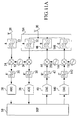
- FIGURE 1A A standard allocation of frequency spectrum for use in a wireless network is illustrated in FIGURE 1A.
- up-link traffic includes all communications from Mobile Terminals (MTs) to Base Transceiver Stations (BTSs) and down-link traffic includes all communications from the BTSs to the MTs.
- BTSs Base Transceiver Stations
- F.G. Frequency Gap
- frequency spectrum allocation such as that illustrated in FIGURE 1A is the implementation of the cellular communications band in North America.
- up-link traffic is assigned the block of frequencies between 824 and 849 MHz and down-link traffic is assigned the block of frequencies between 869 and 894 MHz, thus maintaining a frequency separation of exactly 45 MHz between up-link and down-link channels.
- each sub-block comprising a plurality of Radio Frequency (RF) channels.
- RF Radio Frequency
- their sub-block within the A block (the A sub-block) and their sub-block within the B block (the B sub-block) are located at relatively the same positions within their respective blocks.
- each of the Radio Frequency (RF) channels within the A sub-block has a corresponding RF channel within the B sub-block at a fixed frequency offset, the fixed 45 MHz frequency offset being the same for all of the RF channels within all of the sub-blocks.
- the fixed frequency offset allows for a single oscillator to be implemented within each MT for both the up-link and down-link communications. If there was a variable frequency offset, an oscillator would have to be implemented for each possible offset, thus increasing costs and power consumption for the MT considerably.
- FIGURE 1B illustrates the situation in which there is a plurality of frequency bands available for use by the MTs, particularly the cellular band and the PCS band.
- This new system will preferably allow for fixed offsets to be maintained between the paired up-link and down-link traffic, thus allowing for relatively simple and cheap MT implementations, while also allowing for additional bandwidth to be assessable for bandwidth hungry down-link communications.
- the present invention is directed to apparatus and methods for implementing asymmetrical wireless communications without significant wastage of bandwidth within the up-link block of frequency spectrum.
- the frequency spectrum is divided such that a single up-link block is paired with a plurality of corresponding down-link blocks of similar bandwidth size and respective fixed frequency offsets.
- MTs that utilize different down-link blocks share a common up-link block so that, in ideal statistical situations, the up-link block statistically runs out of bandwidth at approximately the same time as the combination of the down-link blocks.
- the present invention is a Base Transceiver Station (BTS) arranged to be implemented within a wireless network.
- the BTS includes one or more antennas; at least one receive apparatus coupled to the one or more antennas and first and second transmit apparatus each coupled to the one or more antennas.
- the receive apparatus operates to receive up-link signals from a plurality of mobile terminals within the wireless network via a channel within a first frequency block.
- the first transmit apparatus operates to transmit down-link signals to a first set of the plurality of mobile terminals via a channel within a second frequency block.
- the second transmit apparatus operates to transmit down-link signals to a second set of the plurality of mobile terminals via a channel within a third frequency block.
- the channels within the first and second frequency blocks have a first predetermined frequency offset and the channels within the first and third frequency blocks have a second predetermined frequency offset.
- this first predetermined frequency offset is set by the relative frequency tuning between first and second narrow-band BPFs within the receive and first transmit apparatus respectively while the second predetermined frequency offset is set by the relative frequency tuning between first and third narrow-band BPFs within the receive and second transmit apparatus respectively.
- the first predetermined frequency offset is set by a relative frequency difference between first and second reference oscillation signals input to the receive and first transmit apparatus respectively while the second predetermined frequency offset is set by a relative frequency difference between first and third reference oscillation signals input to the receive and second transmit apparatus respectively.
- the present invention is a wireless network including a plurality of mobile stations and a Base Transceiver Station (BTS).
- the BTS operates to: receive up-link signals from each of the mobile terminals via a channel within a first frequency block, transmit down-link signals to a first set of the plurality of mobile terminals via a channel within a second frequency block and transmit down-link signals to a second set of the plurality of mobile terminals via a channel within a third frequency block.
- the present invention is a method for utilizing frequency spectrum within a wireless network.
- the method includes receiving up-link signals from each of a plurality of mobile terminals via a channel within a first frequency block.
- the method includes transmitting down-link signals to a first set of the plurality of mobile terminals via a channel within a second frequency block and transmitting down-link signals to a second set of the plurality of mobile terminals via a channel within a third frequency block.
- the present invention is a mobile terminal arranged to be implemented within a wireless network.
- the mobile terminal includes an antenna, a transmit apparatus coupled to the antenna and a plurality of receive apparatus that are each coupled to the antenna.
- the transmit apparatus operates to transmit up-link signals to a Base Transceiver Station (BTS) within the wireless network via a channel within a first frequency block.
- BTS Base Transceiver Station
- the plurality of receive apparatus operate to receive down-link signals from the BTS via channels within a plurality of other corresponding frequency blocks.
- the present invention is a Base Transceiver Station (BTS) arranged to be implemented within a wireless network.
- the BTS including means for receiving up-link signals from a plurality of mobile terminals within the wireless network via a channel within a first frequency block; and means for transmitting down-link signals to a first set of the plurality of mobile terminals via a channel within a second frequency block and transmitting down-link signals to a second set of the plurality of mobile terminals via a channel within a third frequency block.
- the present invention is a mobile terminal arranged to be implemented within a wireless network.
- the mobile terminal including means for transmitting up-link signals to a Base Transceiver Station (BTS) within the wireless network via a channel within a first frequency block; and means for receiving down-link signals from the BTS via channels within a plurality of other corresponding frequency blocks.
- BTS Base Transceiver Station
- the present invention is a Base Transceiver Station (BTS) arranged to be implemented within a wireless network.
- the BTS includes one or more antennas, at least one receive apparatus coupled to the one or more antennas and at least one transmit apparatus also coupled to the one or more antennas.
- the receive apparatus operates to receive up-link signals from a plurality of mobile terminals within the wireless network via a channel within a first frequency block while the transmit apparatus operates to transmit down-link signals to a first set of the plurality of mobile terminals via a channel within a second frequency block.
- the frequency offset between the channels within the first and second frequency blocks is dynamically controlled.
- the present invention is similar to that of the fifth broad aspect, but is directed to a mobile terminal with an antenna, transmit apparatus and receive apparatus, the transmit and receive apparatus being similar to those within the fifth broad aspect.
- the present invention is directed to apparatus and methods for using frequency spectrum within a wireless network asymmetrically between up-link and down-link communications.
- a single up-link block of frequency spectrum corresponds to a plurality of down-link blocks. Therefore, for each RF channel within the up-link block, there are a plurality of corresponding RF channels for down-link communications, one at a corresponding point in each of the plurality of down-link blocks.
- a MT can be assigned significantly different bandwidths with respect to up-link and down-link communications.
- the up-link traffic can be assigned a small bandwidth (for example 1 kbps) while the down-link traffic can be assigned a relatively large bandwidth (for example 100 kbps).
- FIGURE 2 depicts a block diagram of a well-known BTS implemented within a wireless network with the frequency spectrum allocation scheme of FIGURE 1A.
- the BTS comprises a first receive path including a first antenna 20 coupled in series with a first wide-band BPF 22, a first down-converter 24, a first narrow-band BPF 26 and a first Analog-to-Digital Converter (ADC) 28; a second receive path, used for diversity reception of the same signal, including a second antenna 30 coupled in series with a second wide-band BPF 32, a second down-converter 34, a second narrow-band BPF 36 and a second ADC 38; and a transmit path including a Digital-to-Analog Converter (DAC) 40 coupled in series with a third narrow-band BPF 42, an up-converter 44, a third wide-band BPF 46 and the second antenna 30.
- DAC Digital-to-Analog Converter
- a Digital Signal Processor (DSP) 50 is independently coupled to the output of the first ADC 28, the output of the second ADC 38 and the input of the DAC 40 while an oscillator 52 is independently coupled to the first down-converter 24, the second down-converter 34 and the up-converter 44.
- DSP Digital Signal Processor
- the BTS operates to receive the same radio signals from MTs on both the first and second receive diversity paths, these signals including voice or data information within one of the RF channels of the up-link block (the A block within FIGURE 1A). These signals are received at the first and second antennas 22,32 and forwarded to their respective first and second wide-band BPFs 22,32. At the BPFs 22,32, the signals are filtered such that only the signals within the frequencies of the A frequency block or a sub-block of the A block (depending upon the design) are forwarded, the remaining frequencies containing noise or other unwanted signals being removed.
- the filtered signals are received at the respective down-converters 24,34 and down-converted from Radio Frequency (RF) to either an intermediate frequency or baseband frequency.
- RF Radio Frequency
- These down-converted signals are then further filtered by their respective narrow-band filters 26,36 which limit the signals to a particular frequency channel or limited set of frequency channels.
- the channel-filtered signals are converted to digital signals by their respective ADCs 28,38.
- the digital results are output from the ADCs 28,38 and received at the DSP 50 where they are processed.
- One function that is performed within the DSP 50 is the logical combination of the digital signals to reduce the error rate and improve the signal quality.
- the receive paths may contain one or more low-power amplification stages (not shown).
- the DSP 50 operates to output signals to the transmit path, these signals being digital representations of voice or data information. These digital signals are first sent to the DAC 40 where they are converted to analog signals at a predetermined frequency. Next, the resulting analog signals are filtered by the third narrow-band BPF 42 which limits the signals to a particular frequency channel, removing any noise generated at the DAC 40 on other frequencies. The channel-filtered analog signals are then up-converted to an RF channel within the B block by the up-converter 44 and further filtered by the third wide-band BPF 46 which removes any signals within frequencies outside of the B frequency block or a specified B sub-block (depending upon the design). The resulting signals are subsequently output via the second antenna 30. It should be recognized that the transmit path may contain one or more amplification stages.
- the oscillator 52 within the BTS of FIGURE 2 provides the reference frequency for the down-conversion and up-conversion operations.
- the reference frequency can be the same for both the down-conversion and up-conversion operations due to the up-link and down-link frequency spectrum blocks being relatively close in frequency, and the separation being fixed. With these blocks being close, the frequency offset between the A and B blocks can be implemented with the first and second narrow-band BPFs 26,36 being tuned differently than the third narrow-band BPF 42.
- the second and third wide-band BPFs 32,46 that are both coupled to the second antenna 30 could be seen as comprising a duplexer 54.
- the filters 32,46 essentially operate to split signals traversing the duplexer 54, thus allowing signals on one frequency band (within the A block) to be input and signals on a second frequency band (within the B block) to be output with the use of the single antenna.
- the receive antennas and transmit antennas are shared between many independent transceivers and thus, the BPF 46 could be used with other similar BPFs (tuned to other B block frequencies) to combine other independent transmissions which share the same antenna.
- BPF 46 could be implemented as a relatively narrow-band filter for combining and a wide-band filter for duplex purposes. Further, it is noted that some implementations may not share a common antenna between transmit and receive paths.
- FIGURE 3 is a block diagram of a well-known MT implemented within a wireless network with a frequency spectrum allocation scheme of FIGURE 1A.
- the MT comprises a receive path including an antenna 60 coupled in series with a first wide-band BPF 62, a down-converter 64, a first narrow-band BPF 66 and an ADC 68; and a transmit path including a DAC 70 coupled in series with a second narrow-band BPF 72, an up-converter 74, a second wide-band BPF 76 and the antenna 60.
- the MT comprises a DSP 80 that is independently coupled to the ADC 68 and the DAC 70 and an oscillator 82 that is coupled to the down-converter 64 and the up-converter 74.
- the receive operation within the MT of FIGURE 3 is similar to the receive operation described above for the BTS of FIGURE 2.
- the MT operates to receive signals from a BTS on its receive path, these signals including voice or data information within one of the RF channels of the down-link block (the B block within FIGURE 1A).
- the processing of these signals after being received occurs in a similar manner to that described for each of the receive paths within the BTS of FIGURE 2 but with two main modifications.
- the first wide-band BPF 62 filters the received signals such that only signals within the frequencies of the B block or a sub-block of the B block (depending upon the design) are forwarded while the first narrow-band filter 66 limits the received signals to a particular frequency channel or limited set of frequency channels that corresponded, prior to being down-converted, to the B frequency block.
- the wide-band BPF 62 and the narrow-band BPF 66 would be tuned similarly to the wide-band BPF 46 and the narrow-band BPF 42 respectively of FIGURE 2. It is noted that there may not generally be two receive paths within the MT since, for convenience and cost to the user, there is generally only a single antenna.
- the transmit operation of the MT within FIGURE 3 is also similar to that of the transmit operation described above for the BTS of FIGURE 2.
- the key differences is the frequency band with respect to the filtering that is being performed by the second narrow-band BPF 72 and the second wide-band BPF 76.
- the analog signals output from the DAC 70 are filtered to limit the signals to a particular frequency channel, removing any noise within other frequencies that were generated within the DAC 70.
- the analog signals output from the up-converter 74 are filtered to remove any frequency that is outside of the A block or a specific A sub-block (depending upon the design).
- the narrow-band BPF 72 and the wide-band BPF 76 would be tuned similarly to the narrow-band BPFs 26,36 and the wide-band BPFs 22,32 respectively of FIGURE 2.
- the oscillator 82 can provide the reference frequency for the down-conversion and up-conversion operations within the MT of FIGURE 3 due to the difference in tuning within the narrow-band BPFs 66,72, this difference in tuning maintaining the frequency offset between the A and B frequency blocks. Further, it would be understood that the first and second wide-band BPFs 62,76 that are both coupled to the antenna 60 can be seen to comprise a duplexer 84.
- the filters 62,76 essentially operate to split signals traversing the duplexer 84, thus allowing signals on one frequency band (within the B block) to be input and signals on a second frequency band (within the A block) to be output with the use of the single antenna.
- the MT may use amplification stages in the receive path and/or the transmit path.
- FIGURE 4 is a graphical illustration of a frequency spectrum allocation scheme according to an embodiment of the present invention.
- A an up-link block labelled A
- B a down-link block labelled B
- a frequency separation between the A and B blocks similar to the frequency spectrum allocation of FIGURE 1A.
- the frequency spectrum allocation of FIGURE 4 comprises a second down-link block labelled block C.
- the C block the second down-link block
- the C block is immediately adjacent to the B block (the first down-link block) with no band between them.
- the C block could be implemented in a band separate from the B block or the C block could occur elsewhere in the frequency spectrum.
- the frequency spectrum allocation of the present invention has been illustrated within FIGURE 4 with an up-link block adjacent to two down-link blocks, this should not limit the scope of the present invention.
- the ratio of down-link blocks to up-link blocks could be modified. In many cases in which data traffic is implemented, the ratio should be increased such that there are more down-link blocks per up-link block.
- the up-link blocks could outnumber the down-link blocks while still applying the technique of the present invention to accomplish this.
- the relative location of the up-link and down-link blocks does not necessarily have to be adjacent. One or more of these blocks could be at different locations within the frequency spectrum, the consequences of which will be described below. (for example, with the frequency offset being large between blocks, additional oscillator(s) within the BTS and at least some of the MTs may be necessary for proper up/down-conversions) .
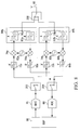
- FIGURE 5 illustrates a sample block diagram of a BTS according to the present invention implemented within a wireless network with a frequency spectrum allocation scheme of FIGURE 4.
- the BTS is identical to that described above for the well-known BTS of FIGURE 2 but with an additional transmit path implemented and modifications within the DSP as will be described herein below.
- the additional transmit path includes a second DAC 140 coupled in series with a fourth narrow-band BPF 142, a second up-converter 144, a fourth wide-band BPF 146 and the second antenna 30.
- this second transmit path could make the duplexer 154 as depicted in FIGURE 5 also perform combining, although alternatively the fourth wide-band BPF 146 could be independently coupled to a different antenna (not shown) (possibly antenna 20, via a second duplexer).
- the BTS of FIGURE 5 comprises a second oscillator 152 that is coupled to the second up-converter 144.
- This second oscillator 152 operates at a modified frequency from that of the first oscillator 52 so that the analog signals output from the narrow-band BPF 142 will be up-converted to the appropriate frequency band for the C block, that being with the appropriate frequency offset with respect to the A and B blocks.
- This additional transmit path is the same as that previously described above for the BTS of FIGURE 2 but with the fourth wide-band BPF 146 being tuned to the C block frequency band and the addition of the second oscillator 152.
- the DSP 50 is modified so that the DAC 140 outputs at a new frequency and a modified narrow-band BPF replaces the BPF 142.
- the reference frequency generated from the oscillator 52 could be used within the second up-converter 144 with the new frequency from the narrow-band BPF 142 being tuned such that it maintains the frequency offset between the B and C blocks.
- the key advantage of the first described implementation of the BTS of FIGURE 5 is that the additional transmit path could be implemented as a separate module to a pre-existing product, thus allowing quick integration within pre-existing networks and further allowing for different customers to receive different options. Further, the first described implementation allows for the previously designed narrow-band BPF 42 to be implemented as the narrow-band BPF 142.
- the key advantage of the alternative embodiment described above is the ability to remove the second oscillator 152, thus reducing cost and space requirements.
- each up-link frequency in the A block is paired with a corresponding down-link frequency in the B block and also with a corresponding down-link frequency in the C block.
- the BTS of FIGURE 5 is specific for two transmit paths on two down-link frequency blocks, it should be recognized that further transmit paths could be implemented in a similar manner, thus allowing for wireless networks with greater than two down-link frequency blocks for each up-link frequency block as will be described below.
- the BTS can receive data or voice via RF channels within the A frequency block while it can transmit data or voice via paired RF channels within either the B or C frequency blocks.
- the decision with respect to which down-link block (B block or C block) to utilize for particular down-link data/voice depends upon the capabilities of the MT that is concerned as will be described herein below with reference to the simplified flow chart of FIGURE 7.
- the MTs communicating with the BTS of FIGURE 5 can be grouped into at least two different groups, those that transmit data/voice on RF channels within the A frequency block and receive data/voice on paired RF channels within the B frequency block, similar to the MT illustrated within FIGURE 3, and those that transmit data/voice on RF channels within the A frequency block and receive data/voice on paired RF channels within the C frequency block, as will now be described with reference to FIGURE 6.
- the MT of FIGURE 6 is a slightly modified version of the MT of FIGURE 3.
- the key differences between the MT of FIGURE 3 and that of FIGURE 6 is the difference within the receive path in terms of the tuning of the BPFs.
- the wide-band BPF 62 of FIGURE 3 is replaced with a wide-band BPF 162 which filters out all noise and signals not within the frequency band of the C block instead of the frequency band of the B block.
- the narrow-band BPF 66 within FIGURE 3 is replaced with a narrow-band BPF 166 which filters the output of the down-converter 64 such that only the selected channel originating from within the C block is forwarded to the ADC 68.
- the tuning of the narrow-band BPF 166 maintains the appropriate frequency offset between the A and C blocks.
- the appropriate frequency offset between the A and C blocks could be maintained with the use of a different oscillator being utilized for the down-conversion operation from the oscillator that is utilized for the up-conversion operation (hence oscillator 82 within FIGURE 6 representing two oscillators).
- the narrow-band BPF 166 could be the same as the narrow-band BPF 66 of FIGURE 3. Further, this would allow for the C frequency block to be significantly displaced from the A frequency block.
- various MTs according to FIGURES 3 and 6 are communicating with a BTS according to FIGURE 5.
- an algorithm must be operated within the DSP 50 of the BTS and/or the cellular switching, call handling and control system that communicates with the BTS to determine which transmit path data/voice should be transmitted to any particular MT.
- a simplified algorithm that could be utilized in the DSP 50 is now described with reference to FIGURE 7.
- the BTS DSP 50 and attached cellular switching, call handling and control system receives and processes data/voice signals from the ADCs 28,38 as depicted at step 180.
- This processing preferably includes logically combining the signals received from the two receive paths in order to improve the signal quality and processing for the particular format (CDMA, TDMA, etc.) that the signals relate. Of course, if there were only one receive path, this logical combining would not be necessary. Further, the processing includes determining where to forward the data/voice signals. If the received signals comprise an Internet request packet, this data could be routed to an Internet server for processing and result in large quantities of data information being returned for subsequent transmitting to the particular MT.
- the DSP 50 and attached cellular switching, call handling and control system determines at step 182 which MT corresponds to the received data/voice signals. This determination can be achieved with well-known wireless BTS algorithms. With this determination, at step 184, the DSP 50 within the BTS of FIGURE 5 checks the frequency capabilities of the determined MT to determine its corresponding down-link frequency block (in the case of the BTS of FIGURE 5, the down-link frequency block being one of the B or C frequency blocks). This look-up is preferably performed with an internal database that is updated during initial handshaking between the MT and the BTS, the MT transmitting information indicating its down-link frequency block during this handshaking procedure.
- step 186 based upon the look-up at step 184, there is a determination to send data via RF channels within the B frequency block or the C frequency block. If the data/voice signals are to be sent via the B frequency block, the digital signals are output from the DSP 50 to the DAC 40 while, if the data/voice signals are to be sent via the C frequency block, the digital signals are output from the DSP 50 to the DAC 140.
- MTs are designed such that they have access to the up-link frequency block along with two down-link frequency blocks, hereinafter referred to as dual-band MTs, or two or more down-link frequency blocks, hereinafter referred to as multi-band MTs.
- the well-known dual-band MT is implemented within a wireless network with a frequency spectrum allocation scheme of FIGURE 1B.
- the MT is similar to the MT of FIGURE 3 but with two receive paths (one for each of the B frequency block and the Y frequency block) and two transmit paths (one for each of the A frequency block and the X frequency block).
- the shared components of the receive paths include the antenna 60 and the ADC 68 while the shared components for the transmit paths include the DAC 70 and the antenna 60.
- the remaining components of the receive paths are duplicated for the two possible down-link frequency blocks that the MT can receive from, these components including wide-band BPFs 62a,62b coupled in series with respective down-converters 64a,64b and respective narrow-band BPFs 66a,66b.
- the remaining components of the transmit paths are duplicated for the two possible up-link frequency blocks that the MT can transmit to, these components including narrow-band BPFs 72a,72b coupled in series with respective up-converters 74a,74b and respective wide-band BPFs 76a,76b.
- independent oscillators 82a,82b are required for generating different reference frequencies for the two sets of up/down-converters.
- the transition from one band to the other band within the MT of FIGURE 8 is performed with the use of switches 200,202,204 that couple the shared components to the frequency band specific components.
- the antenna 60 is coupled via switch 200 to both of the duplexers 84a,84b comprising the wide-band BPFs 62a,72a and the wide-band BPFs 62b,72b respectively.
- the narrow-band BPFs 66a,66b are coupled to the ADC 68 via switch 204 and the narrow-band BPFs 72a,72b are coupled to the DAC 70 via switch 202.
- Each of the switches 200,202,204 has two possible operating positions, one in which the corresponding shared component is coupled to the components of the A/B frequency band and one in which the corresponding shared component is coupled to the components of the X/Y frequency bands.
- FIGURE 9 is a sample block diagram of a dual-mode MT according to the present invention implemented within a wireless network with a frequency spectrum allocation scheme of FIGURE 4.
- the MT is essentially an amalgamation of the MTs of FIGURES 3 and 6.
- the key difference between the MT of FIGURE 6 and that of FIGURE 9 is the replacing of the wide-band BPF 162 with the wide-band BPF 206 that is tuned to both the B and C adjacent frequency blocks and the implementation of the narrow-band BPF 66 of FIGURE 3 in parallel with the narrow-band BPF 166 of FIGURE 6.
- each of the narrow-band BPFs 66,166 are tuned for a different frequency offset compared to the A frequency block. This allows the single oscillator 82 in this embodiment to be used for up-link communications in the A frequency block and down-link communications in both the B and C frequency blocks.
- the switch 208 could be implemented directly after the wide-band BPF 206, thus forcing both narrow-band BPFs 66,166 to have a corresponding down-converter 64.
- the two down-converters could have the same reference frequencies input, hence requiring the predetermined frequency offset between the B and C blocks to be set by the tuning of the BPFs 66,166, or could have two different reference frequencies (from two different oscillators) input such that the predetermined frequency offset is set in the down-conversion operation, hence allowing the BPFs 66,166 to be tuned the same.
- the switch 208 could be moved within the duplexer 84 such that it is coupled between the antenna 60 and two wide-band BPFs, one tuned to each of the B and C frequency blocks. In this case, the wide-band BPF 206 would be replaced by these two wide-band BPFs. In an even another alternative embodiment, the switch 210 could be moved directly before the DSP 80 such that the two narrow-band BPFs 66,166 would be coupled to a corresponding ADC similar to ADC 68.
- FIGURE 9 there are numerous implementations of the dual-band MT of FIGURE 9 depending on which components are shared (possibly none, though it would seem advantageous to at least share the antenna 60) and where the predetermined frequency offset is implemented (the down-conversion operation or the narrow-band BPFs). Yet further, it should be recognized that the implementation of FIGURE 9 could be expanded to implementations with more than two down-link frequency blocks with the insertion of additional components that can allow the MT to switch to alternative predetermined frequency offsets related to the additional down-link frequency blocks.
- the switches in the implementation depicted in FIGURE 9 could be of many forms such as mechanical or electrical. Further, these switches could be automatically controlled from a BTS via control signals. For instance, the BTS could determine the operating frequency band for dual-band MTs like that depicted in FIGURE 9 based upon the frequency band capabilities of the BTS and/or its bandwidth usage in the particular frequency bands. For instance, if one band is considered to have very limited available bandwidth, a BTS could select a MT with dual-band capabilities to operate within the frequency band (A/B band or X/Y band) that has the greater available bandwidth.
- FIGURE 10 is a graphical illustration of a simplified wireless network according to an embodiment of the present invention.
- a number of MTs 220,222,224,226 are depicted, one MT 220 being a wireless handset while the remaining MTs 222,224,226 being wireless computers.
- a computer can be any computing device, for example a desktop computer, Palm Pilot or clone and a wireless computer refers to any computer that has a wireless network link.
- a block for four down-link frequency blocks (B, C, D and E blocks) along with a duplex separation band (indicated by an "X") on either side of the up-link frequency block.
- the wireless handset 220 is communicating up-link on a frequency in the A block at 10kbps and communicating down-link on the paired frequency in the B block at 10kbps while the wireless computers 222,224,226 are each communicating up-link on the same A block frequency as each other and the wireless handset 220 at 1 kbps and communicating down-link on the paired frequency in the C, D and E blocks respectively at 100 kbps.
- FIGURE 10 represents one possible network implementation in which a plurality of MTs share a single up-link frequency block, although in reality each of the MTs of FIGURE 10 would represent a large number of MTs. That is, a plurality of MTs would share each paired set of frequencies.
- wireless computer 222 represents a plurality of wireless computers and/or wireless handsets that all transmit up-link communications on a particular channel within the A block and receive down-link communications on a paired channel within the E block.
- wireless handset 220 represents a plurality of wireless computers and/or wireless handsets that all transmit up-link communications on the same channel within the A block and receive down-link communications on a paired channel within the B block.
- Wireless computers 224,226 represent correspondingly similar devices for paired channels within the C and D blocks respectively.
- FIGURE 10 illustrates a situation with particular bit rates for up-link and down-link communications for the wireless handset 220 and the wireless computers 222,224,226, these numbers should be considered one possible implementation while of course further bit rates could be used.
- MTs those being a combination of wireless handsets and wireless computers, within a wireless network is preferably designed in order to achieve appropriate statistical distribution of users such that no one frequency block is more overburdened than other frequency blocks.
- a calculation is first performed to determine the expected ratio between up-link and down-link traffic within the network.
- categories are established encompassing different types of traffic that have varying ratios of down-link traffic to up-link traffic. For instance, down-link:up-link ratios for voice communications, email receiving/sending over the long term, Internet surfing and ftp transfers potentially could be determined to be 1:1, 5:1, 25:1 and 125:1 respectively.
- the percent of overall down-link traffic that is included in each category is statistically determined and, from this, the overall down-link:up-link ratio is calculated. For instance, if it was determined that 40% of down-link traffic is voice communications while the other 60% of down-link traffic is emailing, there would be an up-link traffic requirement of only 52% of the total down-link traffic, hence resulting in a required down-link:up-link ratio of 1.92.
- an appropriate number of down-link frequency blocks are assigned per up-link frequency block. For instance in the first example of a 1.92 ratio, two down-link frequency blocks for a single up-link frequency block would be appropriate while in the second example of a 3.93 ratio, four down-link blocks are appropriate.
- the assignment of up-link and down-link frequency blocks at this level are generally regulated by governments and, thus the ideal ratio of down-link to up-link frequency blocks for a particular company may not be possible.
- the wireless handsets 220 operate as A/B MTs while the wireless computers operate as one of A/C, A/D and A/E MTs.
- a wireless handset utilizes 10 kbps of up-link bandwidth and 10 kbps of down-link bandwidth while a wireless computer utilizes on average 1 kbps of up-link bandwidth and 100 kbps of down-link bandwidth
- 10 wireless computers creates equivalent up-link traffic to a single wireless handset within the A frequency block. This means that for every 10 wireless computers, a single wireless handset cannot utilize the A block for up-link communications.
- the B block is exclusively used by wireless handsets (thus allowing current wireless handset networks to remain compatible to the new network architecture), not all of the bandwidth within the B frequency block will be utilized since not all of the A block will be available for wireless handset communications.
- This problem can be rectified by allowing some wireless computers to utilize the remaining statistical bandwidth within the B frequency block. This can be done by selling some A/B wireless computers or by selling some multi-band wireless computers that include the B frequency block as one of its down-link blocks.
- any one or more of the MTs within FIGURE 10 could be a multi-band MT and hence could allow the BTS to adjust the down-link frequency blocks for these MTs.
- the BTS can reduce the situations in which available bandwidth becomes critical or is inefficiently used.
- a MT operating very high capacity applications could simultaneously use a plurality of down-link channels corresponding to a plurality of down-link blocks.
- a MT in this embodiment is utilizing a plurality of the paired channels for a single application.
- frequency blocks do not generally have to be adjacent to one another, but one or more of the frequency blocks could be isolated from the other blocks, thus simply creating a larger frequency offset between it and the other frequency blocks.
- One key advantage of the implementation of the present invention is the ability to adjust the down-link bandwidth to up-link bandwidth ratio from the standard symmetrical implementation. This ability can result in a significant increase in usage efficiency for the frequency spectrum. With the increasingly skewed down-link to up-link ratios caused by increasing wireless data traffic, the utilization efficiency of the up-link frequency block(s) (sub-blocks) increase significantly with users sharing them between down-link frequency blocks (sub-blocks).
- One disadvantage of the present invention could occur if significant up-link bandwidth is required for such things as up-loading data to a server from a MT. In this case, this large up-link traffic could result in a large monopolization of up-link bandwidth that could cause considerable blocking and/or slowing of voice/data sessions.
- One solution to this problem is simply to limit the up-link bandwidth provided to any user in times of critical up-link bandwidth, thus resulting in a slower uploading of data for this user but no significant side affects to the wireless networks as a whole.
- the up-link frequency block is the same size as each of the down-link frequency blocks, this is not meant to limit the scope of the present invention in its broadest aspect.
- the up-link block and at least one down-link are of different frequency sizes. For one, using different multiplexing standards as discussed above, different block sizes may be necessary. Further, using non-uniform frequency offsets between paired up-link/down-link channels can allow for different sized up-link/down-link frequency blocks.
- one MT could utilize the first channel within the A block for up-link communications and the fifth channel within the B block for down-link communications while a second MT could utilize the first channel within the A block for up-link communications and the fourth channel within the B block for down-link communications while a third MT could utilize the first channel within the A block for up-link communications and the fourth channel within the C block for down-link communications.
Landscapes
- Engineering & Computer Science (AREA)
- Computer Networks & Wireless Communication (AREA)
- Signal Processing (AREA)
- Mobile Radio Communication Systems (AREA)
- Transceivers (AREA)
Applications Claiming Priority (2)
| Application Number | Priority Date | Filing Date | Title |
|---|---|---|---|
| US606690 | 2000-06-30 | ||
| US09/606,690 US6731953B1 (en) | 2000-06-30 | 2000-06-30 | Apparatus and method for asymmetrical frequency spectrum utilization in a wireless network |
Publications (2)
| Publication Number | Publication Date |
|---|---|
| EP1168675A2 true EP1168675A2 (de) | 2002-01-02 |
| EP1168675A3 EP1168675A3 (de) | 2004-07-28 |
Family
ID=24429041
Family Applications (1)
| Application Number | Title | Priority Date | Filing Date |
|---|---|---|---|
| EP01305585A Withdrawn EP1168675A3 (de) | 2000-06-30 | 2001-06-28 | Gerät und Verfahren zur asymetrische Verwendung des Frequenzspektrums in einem drahtlosen Netz |
Country Status (3)
| Country | Link |
|---|---|
| US (1) | US6731953B1 (de) |
| EP (1) | EP1168675A3 (de) |
| CA (1) | CA2345858A1 (de) |
Cited By (1)
| Publication number | Priority date | Publication date | Assignee | Title |
|---|---|---|---|---|
| WO2018024816A1 (fr) * | 2016-08-05 | 2018-02-08 | Sigfox | Procédé et système de communication sans fil entre terminaux et stations de base avec coordination des fréquences montantes et descendantes |
Families Citing this family (14)
| Publication number | Priority date | Publication date | Assignee | Title |
|---|---|---|---|---|
| US6947507B2 (en) * | 2000-11-27 | 2005-09-20 | Calamp Corp. | Spatial-temporal methods and systems for reception of non-line-of-sight communication signals |
| US6914539B2 (en) * | 2002-10-07 | 2005-07-05 | General Electric Company | System and method for a low rate, in-band broadcast communication for medical telemetry |
| US20040198421A1 (en) * | 2003-02-07 | 2004-10-07 | Coan Philip David | Multi-radio terminals with different intermediate frequencies |
| US7218896B1 (en) * | 2003-12-21 | 2007-05-15 | Redpine Signals, Inc. | Multiplexed wireless receiver and transmitter |
| WO2005072468A2 (en) * | 2004-01-28 | 2005-08-11 | Paratek Microwave Inc. | Apparatus and method capable of utilizing a tunable antenna-duplexer combination |
| US20060062249A1 (en) * | 2004-06-28 | 2006-03-23 | Hall David R | Apparatus and method for adjusting bandwidth allocation in downhole drilling networks |
| KR20070073138A (ko) * | 2006-01-03 | 2007-07-10 | 삼성전자주식회사 | 다중 홉 릴레이 방식의 광대역 무선 접속 통신 시스템에서투명 중계하기 위한 장치 및 방법 |
| JP2008177954A (ja) * | 2007-01-19 | 2008-07-31 | Nec Electronics Corp | 受信装置 |
| US9217653B2 (en) * | 2007-09-13 | 2015-12-22 | Rosemount Inc. | High performance architecture for process transmitters |
| KR101452750B1 (ko) * | 2008-01-29 | 2014-10-21 | 삼성전자주식회사 | 동시대기 단말의 수신경로 제어회로 및 방법 |
| US20090307739A1 (en) * | 2008-06-05 | 2009-12-10 | Qualcomm Incorporated | Remote distributed antenna |
| US8812571B2 (en) | 2011-05-12 | 2014-08-19 | Telefonaktiebolaget L M Ericsson (Publ) | Spectrum agile radio |
| US9031567B2 (en) | 2012-12-28 | 2015-05-12 | Spreadtrum Communications Usa Inc. | Method and apparatus for transmitter optimization based on allocated transmission band |
| US11469503B2 (en) * | 2020-02-28 | 2022-10-11 | T-Mobile Usa, Inc. | Self-optimizing wide band array antennas |
Family Cites Families (10)
| Publication number | Priority date | Publication date | Assignee | Title |
|---|---|---|---|---|
| CA2118273C (en) * | 1993-11-23 | 2000-04-25 | Pi-Hui Chao | Method and apparatus for dynamic channel allocation for wireless communication |
| US5812951A (en) * | 1994-11-23 | 1998-09-22 | Hughes Electronics Corporation | Wireless personal communication system |
| GB2310342A (en) * | 1996-02-16 | 1997-08-20 | Northern Telecom Ltd | Dual mode radio transceiver front end |
| US6415162B1 (en) * | 1996-10-11 | 2002-07-02 | Ericsson Inc. | Interstitial sector system |
| US5790959A (en) * | 1996-11-13 | 1998-08-04 | Hewlett-Packard Company | Programmable band select and transfer module for local multipoint distribution service basestation |
| GB2332822B (en) * | 1997-12-23 | 2002-08-28 | Northern Telecom Ltd | Communication device having a wideband receiver and operating method therefor |
| JP4150101B2 (ja) * | 1998-04-10 | 2008-09-17 | 富士通株式会社 | 無線受信装置 |
| WO2000022755A1 (de) * | 1998-10-12 | 2000-04-20 | Siemens Aktiengesellschaft | Verfahren zum betreiben eines mobilfunksystems und basisstationssystem |
| US6487219B1 (en) * | 1999-09-08 | 2002-11-26 | Skyworks Solutions, Inc. | Multi-band receiver having multi-slot capability |
| US6956836B2 (en) * | 2001-05-17 | 2005-10-18 | Ericsson, Inc. | Asymmetric frequency allocation for packet channels in a wireless network |
-
2000
- 2000-06-30 US US09/606,690 patent/US6731953B1/en not_active Expired - Lifetime
-
2001
- 2001-05-01 CA CA002345858A patent/CA2345858A1/en not_active Abandoned
- 2001-06-28 EP EP01305585A patent/EP1168675A3/de not_active Withdrawn
Cited By (2)
| Publication number | Priority date | Publication date | Assignee | Title |
|---|---|---|---|---|
| WO2018024816A1 (fr) * | 2016-08-05 | 2018-02-08 | Sigfox | Procédé et système de communication sans fil entre terminaux et stations de base avec coordination des fréquences montantes et descendantes |
| FR3054946A1 (fr) * | 2016-08-05 | 2018-02-09 | Sigfox | Procede et systeme de communication sans fil entre terminaux et stations de base avec coordination des frequences montantes et descendantes |
Also Published As
| Publication number | Publication date |
|---|---|
| US6731953B1 (en) | 2004-05-04 |
| CA2345858A1 (en) | 2001-12-30 |
| EP1168675A3 (de) | 2004-07-28 |
Similar Documents
| Publication | Publication Date | Title |
|---|---|---|
| US6731953B1 (en) | Apparatus and method for asymmetrical frequency spectrum utilization in a wireless network | |
| KR100559763B1 (ko) | 코드 분할 다중 접속 전송 시스템용 이동국 | |
| EP0966115B1 (de) | Sende-Empfänger für drahtlose Kommunikation | |
| US8121645B2 (en) | Software defined radio base station and configuration method | |
| CA2154795C (en) | An apparatus and method for digitally processing signals in a radio frequency communication system | |
| KR100782866B1 (ko) | 비대칭 채널 할당을 이용하는 무선 데이터 통신 방법 | |
| US7272366B2 (en) | Method and apparatus for reducing RF filter induced distortion in a wide bandwidth wireless system by the use of channel-dependent RF filter compensation | |
| EP1398887A1 (de) | Doppelband-Diversitätsempfänger | |
| US6359866B1 (en) | Base station having transceivers used for communicating voice and packet data signals | |
| US20080311925A1 (en) | Base station, mobile communication system and channel assignment method | |
| KR20180041562A (ko) | 이동형 기지국 장치 및 이를 이용한 무선 통신 방법 | |
| US11075742B2 (en) | Devices and methods for asymmetrical multicarrier transmission and reception | |
| US20050002360A1 (en) | Method of and apparatus for communication via multiplexed links | |
| EP1377097B1 (de) | Verfahren und Vorrichtung zur Steuerung der Übertragungsratenumschaltung für ein Mobilkommunikationssystem | |
| US20010040882A1 (en) | FDM-CDMA transmitting method, FDM-CDMA receiving method, FDM-CDMA transmitting device and FDM-CDMA receiving device | |
| JPH09289500A (ja) | Tdma通信方法および装置 | |
| GB2383721A (en) | A transmitter for a mobile communication system operable in more than one protocol | |
| KR20010060268A (ko) | 전자기 신호용 송신/수신 장치, 송신/수신 셀, 송신/수신국 및 주파수 호핑 방법 | |
| KR101180110B1 (ko) | 듀얼 신호처리 기능이 구비된 이동 통신 단말기 및 그 신호처리 방법 | |
| KR20030060675A (ko) | 멀티캐리어 통신시스템의 송신기 및 그에 의한 신호 송신방법 | |
| Smitha et al. | A reconfigurable low complexity architecture for channel adaptation in cognitive radio | |
| Panasik et al. | The Challenges of | |
| Smitha et al. | A Low Power Reconfigurable Channel Filter Using Multi-Band and Masking Architecture for Channel Adaptation in Cognitive Radio |
Legal Events
| Date | Code | Title | Description |
|---|---|---|---|
| PUAI | Public reference made under article 153(3) epc to a published international application that has entered the european phase |
Free format text: ORIGINAL CODE: 0009012 |
|
| AK | Designated contracting states |
Kind code of ref document: A2 Designated state(s): AT BE CH CY DE DK ES FI FR GB GR IE IT LI LU MC NL PT SE TR |
|
| AX | Request for extension of the european patent |
Free format text: AL;LT;LV;MK;RO;SI |
|
| RAP1 | Party data changed (applicant data changed or rights of an application transferred) |
Owner name: NORTEL NETWORKS LIMITED |
|
| PUAL | Search report despatched |
Free format text: ORIGINAL CODE: 0009013 |
|
| AK | Designated contracting states |
Kind code of ref document: A3 Designated state(s): AT BE CH CY DE DK ES FI FR GB GR IE IT LI LU MC NL PT SE TR |
|
| AX | Request for extension of the european patent |
Extension state: AL LT LV MK RO SI |
|
| RIC1 | Information provided on ipc code assigned before grant |
Ipc: 7H 04Q 7/30 A |
|
| 17P | Request for examination filed |
Effective date: 20041229 |
|
| AKX | Designation fees paid |
Designated state(s): DE FR GB |
|
| 17Q | First examination report despatched |
Effective date: 20060320 |
|
| STAA | Information on the status of an ep patent application or granted ep patent |
Free format text: STATUS: THE APPLICATION IS DEEMED TO BE WITHDRAWN |
|
| 18D | Application deemed to be withdrawn |
Effective date: 20080814 |