EP1168671A2 - Anordnung zur Steuerung der Aufwärtsstärke für Satelliten Kommunikationssystem mit Satelliten an bord Verarbeitung und Schätzung des Signalschwundes - Google Patents
Anordnung zur Steuerung der Aufwärtsstärke für Satelliten Kommunikationssystem mit Satelliten an bord Verarbeitung und Schätzung des Signalschwundes Download PDFInfo
- Publication number
- EP1168671A2 EP1168671A2 EP01305411A EP01305411A EP1168671A2 EP 1168671 A2 EP1168671 A2 EP 1168671A2 EP 01305411 A EP01305411 A EP 01305411A EP 01305411 A EP01305411 A EP 01305411A EP 1168671 A2 EP1168671 A2 EP 1168671A2
- Authority
- EP
- European Patent Office
- Prior art keywords
- uplink
- satellite
- data
- signal
- power control
- Prior art date
- Legal status (The legal status is an assumption and is not a legal conclusion. Google has not performed a legal analysis and makes no representation as to the accuracy of the status listed.)
- Withdrawn
Links
Images


Classifications
-
- H—ELECTRICITY
- H04—ELECTRIC COMMUNICATION TECHNIQUE
- H04B—TRANSMISSION
- H04B7/00—Radio transmission systems, i.e. using radiation field
- H04B7/14—Relay systems
- H04B7/15—Active relay systems
- H04B7/185—Space-based or airborne stations; Stations for satellite systems
- H04B7/1851—Systems using a satellite or space-based relay
- H04B7/18513—Transmission in a satellite or space-based system
-
- H—ELECTRICITY
- H04—ELECTRIC COMMUNICATION TECHNIQUE
- H04B—TRANSMISSION
- H04B7/00—Radio transmission systems, i.e. using radiation field
- H04B7/14—Relay systems
- H04B7/15—Active relay systems
- H04B7/185—Space-based or airborne stations; Stations for satellite systems
- H04B7/1853—Satellite systems for providing telephony service to a mobile station, i.e. mobile satellite service
- H04B7/18539—Arrangements for managing radio, resources, i.e. for establishing or releasing a connection
- H04B7/18543—Arrangements for managing radio, resources, i.e. for establishing or releasing a connection for adaptation of transmission parameters, e.g. power control
Definitions
- the invention relates to an uplink power control system and more particularly to an uplink power control system employing fade estimation, on-board processing and feedback signaling, and autonomous transmit power adjustment per carrier frequency at terminals.
- a number of existing uplink power control systems for satellite communication systems employ open loop power control and therefore provide no feedback to terminals or stations in the communication system regarding power levels of signals received at a satellite following transmission from the terminals or stations.
- Other uplink power control systems such as those described in U.S. Patent Nos. 5,619,525 and 6,097,752 employ closed loop power control; however, the satellites are repeaters and do not generate feedback data based on received signals from terminals. In other words, these systems are bent-pipe systems whereby the satellite does not impart intelligence to the power control loops (e.g., a loop between a terminal and a satellite repeater and loop between a ground station and a satellite repeater) employed by the closed loop power system.
- the power control loops e.g., a loop between a terminal and a satellite repeater and loop between a ground station and a satellite repeater
- ULPC uplink power control
- the ULPC algorithm of the present invention receives feedback information generated on-board the satellite.
- the satellite is operable to perform a number of noise and signal-to-noise measurements and signal-to-noise and interference measurements using received uplink signals from terminals and to generate a status packet having information for each terminal relating to its recent uplink signal transmission on a particular channel.
- the ULPC algorithm uses the status packet when determining transmit power for its corresponding terminal when transmitting on that particular channel.
- ULPC system of the present invention employs an essentially constant power beacon signal generated by the satellite and cell cast periodically to terminals.
- the ULPC algorithm at each terminal derives carrier-to-noise data relating to the beacon signal that is used to estimate the downlink fade and facilitate adjustment of terminal transmit power.
- the ULPC algorithm maintains and updates filter tables using feedback data generated by the satellite.
- the tables relate to system variations such as the terminal temperature variation and satellite gain-to-temperature variation, estimated uplink spectrum shape and fade estimation and are used to select terminal transmit power.
- FIG. 1 An illustrative broadband multimedia satellite system 10 constructed in accordance with the present invention is depicted in Fig. 1.
- the payload 21 on-board the satellite 20 in the system 10 performs inter-beam routing among satellite terminals (STs) 40 in different cells.
- the satellite provides for flexible allocation of its demodulator resources among uplink cells and can transmit packets from terminals to one or more terminals in one or more downlink cells using different delivery options such as point-to-point service, cellcasts, multicasts and broadcasts.
- the uplink preferably uses a frequency division multiple access/time division multiple access or FDMA TDMA signal format.
- STs are assigned frequencies and time slots in signal frames at which to transmit signals.
- the system 10 supports different data rates and different types of connections.
- Data rates that can be supported on a single carrier can be, for example, 16.384 Mbps (8E1), 2.048 Mbps (E1) and 512 kbps (E1/4). Lower rates are used when STs enter a fallback mode described below.
- Different connection services include, but are not limited to, connectionless and connection-oriented calls.
- NOCC network operations control center
- NOCC network operations control center
- an ST 40 communicates with the satellite payload 21 directly without first obtaining authorization from the NOCC 28.
- the ST first sends a contention channel request to the payload 21 for uplink bandwidth.
- the payload in turn, sends an assignment to the terminal, as well as a power measurement, to allow the ST to adjust uplink power.
- the payload 21 receives packet segments from the STs 40 via uplink signals, validates signatures provided therein, schedules packets for downlink transmission and then transmits them.
- the present invention provides the system 10 with an uplink power control (ULPC) system 50 which is specifically designed to compensate for the transmission environment.
- ULPC uplink power control
- the major portions of the ULPC system 50 are distributed between the satellite 20 and the ST 40.
- the NOCC 28 plays a lesser role.
- Each ST adjusts its uplink (U/L) transmit power per carrier frequency based on beacon power measurements and satellite feedback (e.g., power measurement of U/L packets).
- the satellite 20 is, therefore, responsible for maintaining a stable beacon signal over time, and for performing power measurements on U/L packets from the STs.
- each ST 40 is preferably provided with an Uplink Power Control (ULPC) algorithm 52 that regulates the ST transmit power to accomplish two objectives.
- the algorithm 52 guarantees an adequate link margin against interference and atmospheric impairments (i.e., satisfy the uplink packet loss rate (PLR) and the power control error (PCE) specifications for the system 10).
- the algorithm 52 compensates for ST and satellite radio frequency (RF) imperfections such as power versus frequency and time variations.
- the satellite payload is preferably provided with a power control module 54 that performs different measurements using received uplink signals from the STs and generates feedback data comprising a beacon signal and status packets that are used by the ULPC algorithm 52 at the STs to adjust transmit power.
- the uplink power control (ULPC) algorithm preferably operates as shown in Fig. 3.
- the algorithm employs a system tracking filter (STF) 56, a frequency table filter (FTF) 58, and a C/N table filter (CNTF) 60.
- STF system tracking filter
- FTF frequency table filter
- CNTF C/N table filter
- the STF 56 tracks changes in the amplitude of the uplink (U/L) chain spectrum.
- the U/L chain spectrum jointly describes the ST transmit spectrum and the satellite receive spectrum.
- the FTF 58 estimates the shape of the U/L chain spectrum.
- the CNTF 60 estimates the U/L fade from the downlink (D/L) beacon signal-to-noise ratio (SNR) measurements.
- D/L downlink
- SNR beacon signal-to-noise ratio
- the inputs to the ULPC algorithm 52 include a ULPC status packet received from the satellite 20, a beacon signal-to-noise ratio (SNR) measurement derived from the beacon signal received from the satellite, a power setting request generated by the satellite terminal software, and the channel (frequency), frame number, and slot number associated with the impending transmission.
- the outputs of the algorithm 52 comprise the selected transmit (TX) power, a request (when needed) for a foreground calibration channel, and a fallback mode indicator.
- Inputs and outputs generated and used within the ULPC algorithm 52 comprise a channel number to index FTF and beacon C/N to indicate CNTF used to compute the transmit (TX) power, a clear sky threshold (e.g., average beacon SNR), and the frame number and slot number associated with the impending transmission.
- TX transmit
- SNR beacon signal-to-noise
- a top-level state diagram of the ULPC algorithm 52 is shown in Fig. 4.
- a power setting request 70 is made to the ULPC algorithm 52.
- the algorithm 52 consults the STF 56, the FTF 58, and the CNTF 60 to compute the appropriate uplink TX power (event 72).
- Periodic beacon SNR measurements (event 78) and satellite feedback (e.g., ULPC status packets) (event 76) are used to update the aforementioned filter and tables (74).
- the ULPC status packets are also used to determine whether the ST should ingress into or egress out of the fallback mode.
- a foreground calibration request (event 80) is issued to track changes in the amplitude of the U/L chain spectrum. A description of these events follows.
- the ST preferably makes beacon SNR measurements every 3 ms. These raw SNR measurements are smoothed with a narrow bandwidth filter to minimize the measurement error and to track the D/L fade. This smoothed value is used to determine a clear sky threshold. The clear sky threshold value is set to the smoothed SNR value if the magnitude of the former is found to be smaller than that of the latter.
- the raw beacon SNR measurements are also filtered using a second wide bandwidth filter. This averaged SNR value is quantized to select an appropriate CNTF bin to compute the uplink TX power for an impending transmission.
- ULPC status packets generated at the satellite 20 are cellcast to individual STs 40 preferably every 96 ms.
- the successful reception and/or the latency of these packets is contingent upon the weather and/or channel impairments and satellite queuing delays.
- the ULPC status packets comprise the noise floor, the SNR, and the signal-to-noise-and-interference ratio (SINR) measured at the satellite.
- the packets also comprise an implicit Reed-Solomon (RS) pass/fail indicator, a frame number, and a slot number that correspond to the aforementioned measurements.
- RS Reed-Solomon
- the contents of each ULPC status packet also correspond to a particular U/L frequency channel.
- Fig. 5 depicts a flow chart for ULPC filter and table updates.
- the ST computes an error metric by measuring the difference between the SNR value reported in the packet and the target SNR value stored within the ST (block 86).
- the frame and slot numbers in the ULPC status packet are compared against those stored in an ST's TX buffer. A match indicates that the ULPC packet in question corresponds to a previous transmission.
- the ULPC table buffer 64 also contains the FTF bin and the CNTF bin used to compute the uplink power for a previous transmission (block 90).
- the aforementioned error metric is used to update the FTF and the CNTF bins referred to in the ULPC table buffer 64 (block 92).
- the FTF 68 is preferably updated only when the smoothed beacon SNR indicates a clear sky condition (i.e., when the absolute difference between the smoothed beacon SNR and the clear sky threshold is less than a predetermined small number.
- the error metric with the implicit RS pass/fail indicator is also used to update the STF (block 94).
- An average of the SNR and the SINR reported in the ULPC status packets is computed and used to update the fallback mode indicator (block 96).
- the RS fail indicator is used to augment the output of the STF by a small, predetermined increment to avoid successive RS failures at the satellite (block 98).
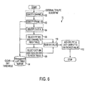
- Fig. 6 shows a flow chart for a ULPC power assignment procedure in accordance with the present invention.
- the ULPC algorithm 52 computes the uplink TX power by adding the output of the STF 56, the FTF 58, and the CNTF 60 to a pre-determined link budget value (block 112).
- the output of the STF is its current memory value.
- the output of the FTF corresponds to the bin associated with the selected channel (blocks 106 and 110).
- the output of the CNTF corresponds to the bin associated with the current quantized, smoothed beacon SNR value (blocks 108 and 110).
- Fig. 7 depicts a flow chart for a ULPC foreground calibration procedure in accordance with an embodiment of the present invention.
- An active ST sets and resets its timeout timer whenever it makes a transmission to a satellite (block 116). However, a period of inactivity (i.e., lack of transmissions) longer than a predetermined period of time (e.g., 10 minutes) causes the ST to issue a foreground calibration request.
- Foreground calibration updates the ULPC filters and tables while the ST is dormant. The request involves selecting a contention channel (block 118), computing the uplink TX power (block 120), transmitting a self loop-back calibration message (112), and resetting the ST timeout timer (block 124).
- the satellite 20 receives an U/L burst from an ST, makes a series of power measurements, and reports the results of these measurements via cellcast to each ST.
- These measurements comprise a noise measurement per carrier using the noise estimation period in each U/L frame, a signal-to-noise ratio measurement for each U/L packet received, a block decode metric from which the ST can derive the signal-to-noise-interference ratio (Ec/(No+Io)) using a pre-defined table lookup, and an implicit Reed-Solomon (RS) decoding pass or fail indicator.
- the NOCC 28 plays a lesser role in the ULPC process.
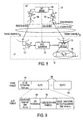
- Fig. 8 illustrates the ULPC system 50 with system parameters that the ULPC system takes into account.
- the transmit and receive RF sections 132 and 130, and 138 and 136, respectively, of an ST 40 and the satellite are shown for illustrative purposes, as well as the ULPC algorithm 52 and a satellite demodulator 134.
- the ST monitors the received beacon slot at each 3ms D/L frame.
- the beacon C/N indicates the current channel condition.
- the ULPC algorithm 52 also receives the ULPC status packet feedback from the satellite for each successful transmission. Using both feedback and beacon C/N measurement, the ULPC compensates the U/L channel fading.
- the ST transmit (TX) spectrum H ST ( f ) 140 is unknown to the ULPC algorithm and the satellite receiver gain is time varying.
- the overall U/L chain spectrum is unknown and time varying.
- the ULPC system 50 also needs to estimate and track the U/L chain spectrum such that U/L power across whole bandwidth is equalized.
- Signal Power: P sig G ST + C 0 + C v - F DL ,
- C 0 is the beacon nominal power
- C v is the beacon power variation
- F DL is the D/L fade
- G ST is the ST receiver gain.
- F n is the noise floor change caused by the fade and N 0 is the nominal receiver noise floor.
- the ST transmit EIRP (in dB): P ST P UL + H ST ( f c ) , where H ST ( f c ) is the ST TX spectrum, f c is the U/L carrier frequency and P UL is the ULPC setting power.
- I i the interference
- G RX ( f ) the satellite receive gain
- N is the satellite receive noise floor
- F UL is the U/L fade
- H ( f ) G RX ( f ) + H ST ( f ) is defined as the U/L chain system spectrum.
- H(f) is unknown and time varying to the ST.
- Thermal noise and channel interference contaminate the signal received at the satellite.
- the satellite preferably continuously monitors signal quality and informs the STs. Each ST adjusts its transmission power such that the expected signal quality is achieved at the satellite.
- the transmission of U/L power control status packets is preferably accomplished in cellcast mode.
- the signal quality in the satellite is reported as:
- each U/L frame 144 has a noise estimation interval where the satellite only receives thermal noise.
- This noise slot 146 is followed by data slots 148.
- Each U/L data slot has UW symbols 150 and coded data symbols 152.
- Noise power N is estimated over the noise estimation interval 146.
- the signal power C is estimated over a slot's UW portion 150.
- the SNR is calculated as (C / N ) SAT .
- Coded block data 152 is received with both additive noise and interference. The number of bit errors can be counted at the Hamming block decoder output.
- the bit error rate is a function of Ec/(No+Io) (SINR), where Io is the interference power. If the SINR and block decoding BER relationship is known, the SINR can be calculated based on the number of bit errors at the block decoder output.
- the payload 21 preferably makes 24, 2 Mbps noise measurements per demodulator 134.
- the noise measurement is performed after a channelizer filter (sqrt-Nyquist filter with 40% excess BW).
- the payload 21 power control module 54 preferably comprises a noise and signal estimator modules (e.g., software components for the PCC).
- the uplink noise sample corresponds to the uplink noise over the 2 Mbps FDMA carrier bandwidth that overlaps the FDMA carrier or carriers being acknowledged.
- the noise sample corresponds to the uplink noise sampled over the bandwidth of the FDMA carrier being acknowledged.
- the noise sample subfield corresponds to the uplink noise samples collected over the bandwidth of the eight 2 Mbps FDMA carriers contained within the 16 Mbps FDMA carrier being acknowledged.
- the signal estimator module cross-correlates the received UW 150 with a stored version of the UW.
- the magnitude of this cross-correlation is proportional to the incoming signal's amplitude (not power).
- the cross-correlation is given by:
- the SNR can be calculated based on the estimated noise variance and the signal amplitude.
- the SNR estimate is the signal amplitude estimate divided by the noise estimate.
- the satellite reports back the SNR measurement to STs in a ULPC status packet.
- C N SAT satellite received C/N
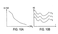
- the U/L fade and the D/L beacon C/N profile is shown in Fig. 10A.
- This figure reflects a long time averaged D/L C/N and U/L fade slope. Since the slope is only an averaged one, the U/L fade is not necessarily equal to the beacon (C/N) times a scaling factor at each instantaneous time due to the U/L and D/L de-correlation.
- An U/L spectrum profile is shown in Fig. 10B. The spectrum shape is unknown but unchanged, and only the spectrum amplitude changes with time.
- the ULPC algorithm 52 Based on the satellite feedback and beacon C N b , the ULPC algorithm 52 preferably derives following metrics to control its U/L power:
- the C/N table P C/N reflects the long-term statistics between D/L C/N and U/L fade.
- the frequency table P f equalizes the U/L chain spectrurn shape (fixed) and P s tracks system variation. Since the ULPC PCE is greater in poor weather conditions, the C/N target C N Target can be raised to achieve required PLR.
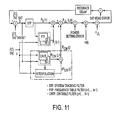
- a closed-loop ULPC algorithm 52 based on satellite feedback and beacon C/N is shown in Fig. 11.
- the closed-loop preferably consists of the following three filters:
- the STF tracks the system variation ( dH ( f )).
- the STF is shared by all frequency bins and all beacon C/N bins. It is updated any time when there is a feedback received.
- the FTF is used to estimate the U/L spectrum shape ( H(f) ).
- the U/L spectrum is divided into M frequency bins.
- the spectrum shape is estimated only when in clear sky, or C N b - C N ref ⁇ Th where C N b is the averaged beacon C/N, C N ref is the beacon reference C/N and Th is the threshold (0.25dB).
- a ULPC algorithm is preferably implemented for all traffic channels. After a ULPC status packet is received and it is considered as valid, the ULPC algorithm preferably performs identically for all traffic channels.
- the traffic channels and their interaction with the ULPC algorithm are shown in Table 1.
- Table 1 U/L Traffic Channels and ULPC Algorithm Interaction Traffic Type Description Interaction with ULPC Control Contention Channel 512/128 Kbps, a random carrier frequency is selected from the list of available contention channels
- the ST receives ULPC status packet and bandwidth on demand (BoD) grant from the satellite.
- the C/N is used by the ULPC algorithm when the BoD request is confirmed and RS is passed.
- a random carrier frequency is selected from the list of available contention channels
- the ST receives ULPC status packet from the satellite.
- the C/N is used by the ULPC algorithm when the RS decoding is passed.
- Foreground Calibration via Contention Channel 512/128 Kbps a random carrier frequency is selected from the list of available contention channels
- the ST sends the ULPC Calibration Message on contention channel when the ST is idle for a long time (10 minutes).
- the ST receives ULPC status packet from the satellite.
- the C/N is used by the ULPC algorithm when the RS decoding is passed.
- volume Channel 512/128 Kbps, 2Mbps and 16Mbps the carrier frequency is dynamically selected by the PCC on the satellite
- the ST receives ULPC status packet from the satellite.
- the C/N is used by the ULPC algorithm when the RS decoding is passed.
- Rate Channel 512/128 Kbps, 2Mbps and 16Mbps the carrier frequency is dynamically selected by the PCC on the satellite or the NOCC
- the ST receives ULPC status packet from the satellite.
- the C/N is used by the ULPC algorithm when the RS decoding is passed.
- the U/L power control is based on the D/L beacon measurement and satellite feedback packets.
- the closed-loop follows same procedures for all contention or traffic channels. Therefore the closed-loop control is identical to all channels.
- the U/L power P UL ( i , j , k ) is set according to STF, FTF and CNTF output.
- a frequency bin is preferably shared by one 2Mbps carrier or four 512Kbps carriers.
- a 16 Mbps channel uses eight frequency bins within its bandwidth.
- CNTF table is built based on the 512Kpbs channel. In order to achieve about same C/N target at the satellite, a margin needs to be added to the U/L power.
- the U/L power is set as: where i is the frequency bin for current transmission ( i is the first bin of eight for a 16Mbps transmission), j is the current beacon bin and Mode_offset is a power offset for different date rate traffic as shown in Table 2. Higher data rate traffic requires a wider receiver bandwidth at the satellite, hence receives higher noise power. In order to achieve same received C/N at the satellite, a power offset is added to the ST transmission power. Table 2: Maximum Power and offset for the different Mode Mode Offset 128 Kbps 0 dB 512 Kbps 0 dB 2 Mbps 6.02 dB 16 Mbps 15.05 dB
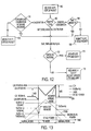
- Fig. 12 is a flow chart depicting ULPC status packet handling for terminal uplink power control.
- the ULPC status packet is received for every ST transmission (block 160).
- the ULPC status packet is processed according to its channel type (block 162). For example, different channel types can be:
- the ULPC algorithm 52 When the ULPC algorithm 52 receives the ULPC status packet, it updates the STF, FTF and CNTF if RS is passed (blocks 172 and 174); otherwise, a fixed power margin is added to the STF to increase the U/L power for next few transmissions (block 176).
- the calibration message referred to in block 168 and the BoD grant referred to in block 164 preferably arrive within selected timeout periods.
- Table 3 An example of the operation of the ULPC algorithm in the ST is shown in Table 3. This table illustrates how the ST operates for different traffic types on each frame and how the various filters in the closed loop get updated.
- Table 3 Example of ULPC Algorithm Operation. Frame No ST-TX P UL ( i , j , k ) ST-RX Update CNTF Update FTF 1 Update STF Comment 1 P UL (5,10,1) Start of Volume transmission. Transmit on freq bin 5; C/N bin 10 and frame #1. 2 P UL (5,10,2) Continue volume transmission.
- foreground calibrations are sent by each ST through the contention channel if there is no transmission for a long time.
- the foreground calibration is triggered by the ULPC algorithm 52 preferably if, and only if, there is no transmission for a selected period of time (e.g., 10 minutes).
- Fallback (FB) mode is used to increase the availability provided to certain satellite communication system 10 customers by reducing the ST uplink data rate during times of heavy rain.
- the reduced data rates are preferably
- the ULPC algorithm requests a switch to enter into and exit from the fallback (FB) mode based the ULPC status packet.
- the Normal mode to FB mode switch preferably depends only on the satellite feedback E 0 N 0 + I 0 (+) SAT ave and not on the beacon C/N.
- Fig. 13 illustrates the ULPC/FB interactions, along with the signal quality, fade and the ST U/L power. As the fade increases, the ST U/L transmit power increases until it reaches its maximum power. Until then, the Ec/(No+Io) at the satellite 20 is maintained at the nominal level, after which it decreases as the fade increases.
- E 0 N 0 + I 0 (+) SAT ave plays an important role in determining when to switch to the FB Mode since it is desirable to maintain the PLR during the rainy fade condition.
- the normal mode is switched to the fallback mode.
- the ULPC algorithm 52 sends a FB request if: • E 0 N 0 + I 0 (+) SAT ave ⁇ E 0 N 0 + I 0 Threshold , and
- the switch to the normal mode is made when C N (+) SAT ave is higher than the ( C/N ) SAT ceiling (( C / N ) SAT nominal+6dB for a 2Mbps channel).
- the ULPC sends a FB Mode Off request if: C N (+) SAT ave > C N Ceiling
Landscapes
- Engineering & Computer Science (AREA)
- Physics & Mathematics (AREA)
- Astronomy & Astrophysics (AREA)
- Aviation & Aerospace Engineering (AREA)
- General Physics & Mathematics (AREA)
- Computer Networks & Wireless Communication (AREA)
- Signal Processing (AREA)
- Radio Relay Systems (AREA)
- Mobile Radio Communication Systems (AREA)
Applications Claiming Priority (2)
| Application Number | Priority Date | Filing Date | Title |
|---|---|---|---|
| US21416500P | 2000-06-26 | 2000-06-26 | |
| US214165P | 2000-06-26 |
Publications (2)
| Publication Number | Publication Date |
|---|---|
| EP1168671A2 true EP1168671A2 (de) | 2002-01-02 |
| EP1168671A3 EP1168671A3 (de) | 2002-12-18 |
Family
ID=22798019
Family Applications (1)
| Application Number | Title | Priority Date | Filing Date |
|---|---|---|---|
| EP01305411A Withdrawn EP1168671A3 (de) | 2000-06-26 | 2001-06-21 | Anordnung zur Steuerung der Aufwärtsstärke für Satelliten Kommunikationssystem mit Satelliten an bord Verarbeitung und Schätzung des Signalschwundes |
Country Status (4)
| Country | Link |
|---|---|
| EP (1) | EP1168671A3 (de) |
| CA (1) | CA2351702A1 (de) |
| IL (1) | IL143820A0 (de) |
| MX (1) | MXPA01006562A (de) |
Cited By (5)
| Publication number | Priority date | Publication date | Assignee | Title |
|---|---|---|---|---|
| GB2407005A (en) * | 2003-10-07 | 2005-04-13 | Roke Manor Research | Controlling interference from a transmitter in one communication system to a receiver in another communication system |
| EP2273693A3 (de) * | 2009-07-08 | 2012-07-25 | ViaSat Inc. | Steuerung der Stärke einer interferenzbeständigen Satellitenverbindung durch Verwendung eines abwärts Bakesignals |
| EP2273694A3 (de) * | 2009-07-09 | 2012-08-01 | ViaSat Inc. | Interferenzbeständige Steuerung der Stärke einer Satellitenverbindung durch aufwärts Geräuschmessung |
| EP2282420A3 (de) * | 2009-07-09 | 2013-12-18 | ViaSat Inc. | MF-TDMA-Satellitenverbindungsleistungssteuerung |
| CN115225134A (zh) * | 2021-04-16 | 2022-10-21 | 中电科航空电子有限公司 | 一种克服雨衰的功率谱密度控制方法及系统 |
Citations (4)
| Publication number | Priority date | Publication date | Assignee | Title |
|---|---|---|---|---|
| WO1998009387A1 (en) * | 1996-08-28 | 1998-03-05 | Ericsson, Inc. | Method and apparatus for improving the link margin in wireless communications |
| EP0837569A2 (de) * | 1996-10-21 | 1998-04-22 | Globalstar L.P. | Fadingdämpfungskontrollanordnung für mehrere Satelliten |
| WO1999021291A1 (en) * | 1997-10-20 | 1999-04-29 | Comsat Corporation | Power output control system for rf communications system |
| EP0969607A2 (de) * | 1998-06-29 | 2000-01-05 | Hughes Electronics Corporation | Satellitemesssystem für Leistungsregelung in der Aufwärtsverbindung und Zeitsynchronisierung |
-
2001
- 2001-06-18 IL IL14382001A patent/IL143820A0/xx unknown
- 2001-06-21 EP EP01305411A patent/EP1168671A3/de not_active Withdrawn
- 2001-06-25 MX MXPA01006562A patent/MXPA01006562A/es unknown
- 2001-06-26 CA CA002351702A patent/CA2351702A1/en not_active Abandoned
Patent Citations (4)
| Publication number | Priority date | Publication date | Assignee | Title |
|---|---|---|---|---|
| WO1998009387A1 (en) * | 1996-08-28 | 1998-03-05 | Ericsson, Inc. | Method and apparatus for improving the link margin in wireless communications |
| EP0837569A2 (de) * | 1996-10-21 | 1998-04-22 | Globalstar L.P. | Fadingdämpfungskontrollanordnung für mehrere Satelliten |
| WO1999021291A1 (en) * | 1997-10-20 | 1999-04-29 | Comsat Corporation | Power output control system for rf communications system |
| EP0969607A2 (de) * | 1998-06-29 | 2000-01-05 | Hughes Electronics Corporation | Satellitemesssystem für Leistungsregelung in der Aufwärtsverbindung und Zeitsynchronisierung |
Cited By (9)
| Publication number | Priority date | Publication date | Assignee | Title |
|---|---|---|---|---|
| GB2407005A (en) * | 2003-10-07 | 2005-04-13 | Roke Manor Research | Controlling interference from a transmitter in one communication system to a receiver in another communication system |
| GB2407005B (en) * | 2003-10-07 | 2006-02-01 | Roke Manor Research | A method of controlling interference from a transmitter in one communication system to a receiver in another communication system |
| US7848730B2 (en) | 2003-10-07 | 2010-12-07 | Roke Manor Research Limited | Method of controlling interference from a transmitter in one communication system to a receiver in another communication system |
| EP2273693A3 (de) * | 2009-07-08 | 2012-07-25 | ViaSat Inc. | Steuerung der Stärke einer interferenzbeständigen Satellitenverbindung durch Verwendung eines abwärts Bakesignals |
| US8385223B2 (en) | 2009-07-08 | 2013-02-26 | Viasat, Inc. | Interference resistant satellite link power control using downlink beacon |
| US8483609B2 (en) | 2009-07-08 | 2013-07-09 | Viasat, Inc. | Interference resistant satellite link power control using uplink noise measurements |
| EP2273694A3 (de) * | 2009-07-09 | 2012-08-01 | ViaSat Inc. | Interferenzbeständige Steuerung der Stärke einer Satellitenverbindung durch aufwärts Geräuschmessung |
| EP2282420A3 (de) * | 2009-07-09 | 2013-12-18 | ViaSat Inc. | MF-TDMA-Satellitenverbindungsleistungssteuerung |
| CN115225134A (zh) * | 2021-04-16 | 2022-10-21 | 中电科航空电子有限公司 | 一种克服雨衰的功率谱密度控制方法及系统 |
Also Published As
| Publication number | Publication date |
|---|---|
| EP1168671A3 (de) | 2002-12-18 |
| CA2351702A1 (en) | 2001-12-26 |
| MXPA01006562A (es) | 2004-08-11 |
| IL143820A0 (en) | 2002-04-21 |
Similar Documents
| Publication | Publication Date | Title |
|---|---|---|
| US7043199B2 (en) | Uplink power control system for satellite communication system employing on-board satellite processing and fade estimation | |
| US8311491B2 (en) | Adaptive data rate control for narrowcast networks | |
| US5511079A (en) | Apparatus and method for controlling forward error correction encoding in a very small aperture terminal | |
| US8131212B2 (en) | Method and apparatus for compensation for weather-based attenuation in a satellite link | |
| US6212360B1 (en) | Methods and apparatus for controlling earth-station transmitted power in a VSAT network | |
| EP2282420B1 (de) | MF-TDMA-Satellitenverbindungsleistungssteuerung | |
| EP2286523B1 (de) | Verfahren und vorrichtung zur kompensation einer auf wetter basierenden dämpfung in einer satellitenverbindung | |
| US7386310B2 (en) | Fallback mode ingress/egress mechanism for satellite communication system | |
| EP3340491A1 (de) | Verfahren und vorrichtung zur kompensation einer auf wetter basierenden dampfung in einer satellitenverbindung | |
| EP2073399B1 (de) | Mehrdimensionale anpassbare Übertragungstechnik | |
| JP2002344368A (ja) | 衛星通信システムのアップリンク電力制御方法及び装置 | |
| EP1168671A2 (de) | Anordnung zur Steuerung der Aufwärtsstärke für Satelliten Kommunikationssystem mit Satelliten an bord Verarbeitung und Schätzung des Signalschwundes | |
| Toshinaga et al. | Bi-directional multimedia satellite communication system employing superposed transmission |
Legal Events
| Date | Code | Title | Description |
|---|---|---|---|
| PUAI | Public reference made under article 153(3) epc to a published international application that has entered the european phase |
Free format text: ORIGINAL CODE: 0009012 |
|
| AK | Designated contracting states |
Kind code of ref document: A2 Designated state(s): AT BE CH CY DE DK ES FI FR GB GR IE IT LI LU MC NL PT SE TR |
|
| AX | Request for extension of the european patent |
Free format text: AL;LT;LV;MK;RO;SI |
|
| PUAL | Search report despatched |
Free format text: ORIGINAL CODE: 0009013 |
|
| AK | Designated contracting states |
Kind code of ref document: A3 Designated state(s): AT BE CH CY DE DK ES FI FR GB GR IE IT LI LU MC NL PT SE TR |
|
| AX | Request for extension of the european patent |
Free format text: AL;LT;LV;MK;RO;SI |
|
| 17P | Request for examination filed |
Effective date: 20030603 |
|
| 17Q | First examination report despatched |
Effective date: 20030724 |
|
| AKX | Designation fees paid |
Designated state(s): DE FI FR GB IT SE |
|
| RAP1 | Party data changed (applicant data changed or rights of an application transferred) |
Owner name: HUGHES NETWORK SYSTEMS, LLC |
|
| STAA | Information on the status of an ep patent application or granted ep patent |
Free format text: STATUS: THE APPLICATION IS DEEMED TO BE WITHDRAWN |
|
| 18D | Application deemed to be withdrawn |
Effective date: 20060502 |