EP1168237B1 - Broad bandwidth, high impedance transponder for electronic identification system - Google Patents
Broad bandwidth, high impedance transponder for electronic identification system Download PDFInfo
- Publication number
- EP1168237B1 EP1168237B1 EP01305265A EP01305265A EP1168237B1 EP 1168237 B1 EP1168237 B1 EP 1168237B1 EP 01305265 A EP01305265 A EP 01305265A EP 01305265 A EP01305265 A EP 01305265A EP 1168237 B1 EP1168237 B1 EP 1168237B1
- Authority
- EP
- European Patent Office
- Prior art keywords
- transponder
- antenna
- feedpoint
- impedance
- input
- Prior art date
- Legal status (The legal status is an assumption and is not a legal conclusion. Google has not performed a legal analysis and makes no representation as to the accuracy of the status listed.)
- Revoked
Links
Images


Classifications
-
- G—PHYSICS
- G06—COMPUTING; CALCULATING OR COUNTING
- G06K—GRAPHICAL DATA READING; PRESENTATION OF DATA; RECORD CARRIERS; HANDLING RECORD CARRIERS
- G06K19/00—Record carriers for use with machines and with at least a part designed to carry digital markings
- G06K19/06—Record carriers for use with machines and with at least a part designed to carry digital markings characterised by the kind of the digital marking, e.g. shape, nature, code
- G06K19/067—Record carriers with conductive marks, printed circuits or semiconductor circuit elements, e.g. credit or identity cards also with resonating or responding marks without active components
- G06K19/07—Record carriers with conductive marks, printed circuits or semiconductor circuit elements, e.g. credit or identity cards also with resonating or responding marks without active components with integrated circuit chips
- G06K19/077—Constructional details, e.g. mounting of circuits in the carrier
- G06K19/07749—Constructional details, e.g. mounting of circuits in the carrier the record carrier being capable of non-contact communication, e.g. constructional details of the antenna of a non-contact smart card
-
- G—PHYSICS
- G06—COMPUTING; CALCULATING OR COUNTING
- G06K—GRAPHICAL DATA READING; PRESENTATION OF DATA; RECORD CARRIERS; HANDLING RECORD CARRIERS
- G06K19/00—Record carriers for use with machines and with at least a part designed to carry digital markings
- G06K19/06—Record carriers for use with machines and with at least a part designed to carry digital markings characterised by the kind of the digital marking, e.g. shape, nature, code
- G06K19/067—Record carriers with conductive marks, printed circuits or semiconductor circuit elements, e.g. credit or identity cards also with resonating or responding marks without active components
- G06K19/07—Record carriers with conductive marks, printed circuits or semiconductor circuit elements, e.g. credit or identity cards also with resonating or responding marks without active components with integrated circuit chips
- G06K19/0723—Record carriers with conductive marks, printed circuits or semiconductor circuit elements, e.g. credit or identity cards also with resonating or responding marks without active components with integrated circuit chips the record carrier comprising an arrangement for non-contact communication, e.g. wireless communication circuits on transponder cards, non-contact smart cards or RFIDs
-
- H—ELECTRICITY
- H01—ELECTRIC ELEMENTS
- H01Q—ANTENNAS, i.e. RADIO AERIALS
- H01Q1/00—Details of, or arrangements associated with, antennas
- H01Q1/12—Supports; Mounting means
- H01Q1/22—Supports; Mounting means by structural association with other equipment or articles
- H01Q1/24—Supports; Mounting means by structural association with other equipment or articles with receiving set
-
- H—ELECTRICITY
- H01—ELECTRIC ELEMENTS
- H01Q—ANTENNAS, i.e. RADIO AERIALS
- H01Q5/00—Arrangements for simultaneous operation of antennas on two or more different wavebands, e.g. dual-band or multi-band arrangements
- H01Q5/30—Arrangements for providing operation on different wavebands
- H01Q5/307—Individual or coupled radiating elements, each element being fed in an unspecified way
- H01Q5/342—Individual or coupled radiating elements, each element being fed in an unspecified way for different propagation modes
- H01Q5/357—Individual or coupled radiating elements, each element being fed in an unspecified way for different propagation modes using a single feed point
- H01Q5/364—Creating multiple current paths
- H01Q5/371—Branching current paths
-
- H—ELECTRICITY
- H01—ELECTRIC ELEMENTS
- H01Q—ANTENNAS, i.e. RADIO AERIALS
- H01Q9/00—Electrically-short antennas having dimensions not more than twice the operating wavelength and consisting of conductive active radiating elements
- H01Q9/04—Resonant antennas
- H01Q9/0407—Substantially flat resonant element parallel to ground plane, e.g. patch antenna
- H01Q9/0421—Substantially flat resonant element parallel to ground plane, e.g. patch antenna with a shorting wall or a shorting pin at one end of the element
Definitions
- THIS invention relates to electronic radio frequency (RF) identification systems comprising a reader and a plurality of transponders.
- the invention more particularly relates to transponders forming part of such a system.
- Known electronic systems of the aforementioned kind comprise an interrogator or reader comprising a transmitter for transmitting an energizing or interrogation signal to the transponders and a receiver for receiving a response signal from the transponders.
- a microprocessor in the reader identifies a particular transponder by a data stream in the response signal.
- Each transponder comprises an antenna connected to an integrated circuit hosting electronic circuitry for receiving and collecting power from the interrogation signal to present a high enough voltage on a voltage storage capacitor, to power the circuitry which in turn generate the aforementioned data stream.
- the data stream is used by the transponder to modulate the energizing signal and to reflect back to the reader a portion of the energy in the energizing signal, by what is known as backscatter modulation.
- US Patent 6,054,925 there is disclosed a transponder with a high input impedance which the applicant believes will improve on the limited effective distance of prior art systems. The higher the input impedance of the integrated circuit and the antenna feedpoint impedance, the higher the voltage recovered from the energizing signal and stored on the capacitor.
- a transponder for an electronic identification system comprising:
- the circuit may have an input impedance comprising a real component and a capacitive reactive component.
- An inductive element may be connected between the antenna and the circuit in parallel with the input impedance and which is operative to resonate with the capacitive component of the input impedance.
- the real part of the input impedance may be at least 400 ohms, typically 1000 ohms and is preferably larger than 1500 ohms.
- the first frequency may be between 850 MHz and 900 MHz and the second frequency may be between 900 MHz and 1 GHz.
- the antenna may comprise any one of a combination of a patch antenna and a transmission line both connected to the feedpoint; a combination of a shorted ring patch antenna and a transmission line both connected to the feedpoint; and a combination of a loop and an appendage to the loop.
- the appendage may comprise a second loop.
- the first and second frequencies may be associated with first and second dimensions of the antenna and the first and second frequencies may be selected by selection of the first and second dimensions.
- the invention also extends to an electronic radio frequency identification system comprising a reader or interrogator and at least one transponder as herein defined and/or described.
- RFID radio frequency identification
- the system comprises a reader 12 and a transponder population 14 comprising transponders 14.1 to 14.n.
- the transponders may be mounted on or otherwise associated with items or articles (not shown) to be counted or identified.
- the transponders are preferably passive transponders in that they derive power to operate, from an energizing signal 16 transmitted by the reader.
- the transponders are similar in configuration and therefore transponder 14.1 only will be described further.
- Transponder 14.1 comprises an antenna 18, an integrated circuit 19 connected to the antenna and comprising a modulator 20, a controller 22 and a memory arrangement 24.
- the reader transmits an energizing signal 16 having a frequency f c towards the transponder population 14.
- the transponders derive their power from this signal as is known in the art and transmit respective response signals 26.1 to 26.n by backscatter modulating the signal in known manner with data pre-stored in memory arrangement 24.
- the reader sequentially locks onto one of the response signals and reads the data as will hereinafter be described. Once the population has been read, the aforementioned items are identified and/or counted.
- the transponder 14.1 comprises an antenna 18 having a feedpoint 30 in a region thereof where there is a current minimum, so that it has a relatively high feedpoint impedance Z A .
- the antenna feedpoint 30 is connected to input C of the aforementioned integrated circuit (IC) 19, having an input impedance Z c .
- IC 19 comprises a capacitance 21 of about 1.95 pF capacitor 21 in parallel with a resistance 23 of larger than 400 ohms, typically larger than 1000 ohms and preferably 1600 ⁇ .
- a parallel tuning inductor 34 is connected between the antenna 18 and IC 19.
- FIG 3 there is shown a diagram of voltage developed across the input impedance Z c of the IC against frequency of an incident energizing signal 16.
- first and second voltage maxima 36 and 38 are developed at first and second frequencies f L and f H respectively.
- the transponder 14.1 provides wideband characteristics, superior to that of prior art transponders.
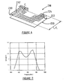
- a first embodiment 118 of an antenna according to the invention for use with a transponder 14.1 is shown in figure 4.
- the antenna 118 is a patch antenna comprising a conductive ground plane 120, on one face of a dielectric layer 122 of about 10mm in thickness and a grid or conductive layer 124 on another face and connected to the ground plane 120 as shown.
- the antenna 118 is driven at feedpoint 130 located in a region where there is a current minimum.
- a conductor or transmission line 132 having a length l 1 is integrated with the patch antenna and is also connected to the feedpoint 130 and layer 124.
- the resulting transponder 14.1 has a voltage against frequency curve at C in figure 2, as shown in figure 5, clearly displaying dual voltage maxima and consequent wideband characteristics.
- the frequencies f L and f H may be manipulated by manipulating dimensions l 1 and l 2 . It is believed that the frequency dependent antenna impedance is substantially matched at frequencies f L and f H to the input impedance Z c , resulting in the voltage maxima developed across the input impedance at C at these frequencies.
- a second embodiment 218 of an antenna according to the invention for use with a transponder 14.1 is shown in figure 6.
- the antenna 218 is a shorted ring patch antenna comprising a ground, plane 220 on one face of an insulating layer 222 of air and a conductive grid or layer 224 on another face and connected to the ground plane 220 as shown.
- the antenna 218 has a feedpoint 230 located in a region where there is a current minimum.
- a transmission line 232 having a length l 1 is integrated with the patch antenna and is also connected to the feedpoint 230.
- the resulting transponder 14.1 has a voltage against frequency curve at C in figure 2, as shown in figure 7. The curve clearly displays dual voltage maxima and consequent wideband characteristics.
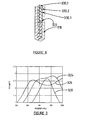
- a third embodiment 318 of an antenna according to the invention for use with a transponder 14.1 is shown in figure 8.
- the antenna 318 is a zigzag hybrid loop.
- Three typical feedpoints 330.1, 330.2 and 330.3 are shown.
- the antenna has a single voltage maximum as shown at 320 in figure 9.
- it exhibits dual voltage maxima characteristics.
- the dual mode operation is caused by different path lengths l 1 and l 2 (clockwise and anti-clockwise) around the loop 322.
- the first and second frequencies are closer together, as shown at 324 in figure 9 and at feedpoint 330.3 the first and second frequencies are further apart, as shown at 326 in figure 9.
- a fourth embodiment 418 of an antenna according to the invention for use with a transponder 14.1 is shown in figure 10.
- the antenna comprises first and second linked loops 420 and 422 and has a feedpoint 430, where IC 19 is connected to the antenna.
- the parallel tuning inductor is shown at 34.
- a curve of voltage at the input of IC 19 against frequency is shown at 432 in figure 11. The dual voltage maxima and consequent wideband characteristics covering the band 840 MHz to 950 MHz is clearly visible.
- the diagram in figure 12 illustrates the effect on the curve of the patch antenna in figure 4, if an inductor 34 is chosen such that the inductor 34 and IC capacitance resonate at any one of three different frequencies (860 MHz; 900 MHz and 940 MHz) in the region of f L and f H .
- the resulting voltage against frequency curves are shown at 500, 502 and 504 in figure 12. It is shown that there is no additional voltage maximum, but that the voltage peaks can be adjusted using an appropriate tuned frequency for the LC network. The same method may be utilized to obtain a flatter response.
Abstract
Description
- THIS invention relates to electronic radio frequency (RF) identification systems comprising a reader and a plurality of transponders. The invention more particularly relates to transponders forming part of such a system.
- Known electronic systems of the aforementioned kind comprise an interrogator or reader comprising a transmitter for transmitting an energizing or interrogation signal to the transponders and a receiver for receiving a response signal from the transponders. A microprocessor in the reader identifies a particular transponder by a data stream in the response signal. Each transponder comprises an antenna connected to an integrated circuit hosting electronic circuitry for receiving and collecting power from the interrogation signal to present a high enough voltage on a voltage storage capacitor, to power the circuitry which in turn generate the aforementioned data stream. The data stream is used by the transponder to modulate the energizing signal and to reflect back to the reader a portion of the energy in the energizing signal, by what is known as backscatter modulation. In the applicant's US Patent 6,054,925, there is disclosed a transponder with a high input impedance which the applicant believes will improve on the limited effective distance of prior art systems. The higher the input impedance of the integrated circuit and the antenna feedpoint impedance, the higher the voltage recovered from the energizing signal and stored on the capacitor.
- It is also known that the higher the aforementioned impedances, the higher the quality factor (Q) of the circuit and consequently the narrower the bandwidth of the transponder becomes. Known transponders with relatively high impedances have a bandwidth of in the order of 1% -2%. The applicant has identified a need for a practical system to cover the
range 860 MHz to 930 MHz and which hence requires a bandwidth of about 7% to 10%. - In US 5,317,330 to Everett there is disclosed a two way communication system wherein a series or resonant circuit and a parallel or anti-resonant circuit are utilized to divide a bandwidth into a transmitting part and a separate receiving part. The result is two discrete narrow bands for use in transmitting and receiving coded information at different frequencies. Such a system would not be able to cover the aforementioned range adequately.
- Accordingly it is an object of the present invention to provide an electronic identification system and a transponder with which the applicant believes the aforementioned disadvantages may at least be alleviated.
- According to the invention there is provided a transponder for an electronic identification system comprising:
- an antenna having an antenna impedance at a feedpoint thereof;
- an electronic circuit having an input impedance at an input thereof, the input being connected to the feedpoint; and
- the antenna impedance having frequency dependent impedance characteristics for developing first and second voltage maxima across the input at first and second frequencies respectively, thereby to provide a continuous operative frequency band for the transponder including the first and second frequencies.
- The circuit may have an input impedance comprising a real component and a capacitive reactive component.
- An inductive element may be connected between the antenna and the circuit in parallel with the input impedance and which is operative to resonate with the capacitive component of the input impedance.
- The real part of the input impedance may be at least 400 ohms, typically 1000 ohms and is preferably larger than 1500 ohms.
- The first frequency may be between 850 MHz and 900 MHz and the second frequency may be between 900 MHz and 1 GHz.
- The antenna may comprise any one of a combination of a patch antenna and a transmission line both connected to the feedpoint; a combination of a shorted ring patch antenna and a transmission line both connected to the feedpoint; and a combination of a loop and an appendage to the loop. The appendage may comprise a second loop.
- The first and second frequencies may be associated with first and second dimensions of the antenna and the first and second frequencies may be selected by selection of the first and second dimensions.
- The invention also extends to an electronic radio frequency identification system comprising a reader or interrogator and at least one transponder as herein defined and/or described.
- The invention will now further be described, by way of example only, with reference to the accompanying diagrams wherein:
- figure 1
- is a block diagram of an electronic radio frequency (RF) identification system;
- figure 2
- is a very basic block diagram of a transponder according to the invention;
- figure 3
- is a basic diagram of voltage against frequency at point C of the transponder according to the invention in figure 2;
- figure 4
- is a diagram of a first embodiment of an antenna forming part of the transponder according to the invention;
- figure 5
- is a diagram of voltage against frequency at point C of the transponder in figure 2 comprising the antenna in figure 4;
- figure 6
- is a diagram of a second embodiment of an antenna forming part of the transponder according to the invention;
- figure 7
- is a diagram of voltage against frequency at point C of the transponder in figure 2 comprising the antenna in figure 6;
- figure 8
- is a diagram of a third embodiment of an antenna forming part of the transponder according to the invention;
- figure 9
- is a diagram of voltage against frequency at point C of the transponder in figure 2 comprising the antenna in figure 8;
- figure 10
- is a diagram of a transponder according to the invention comprising a fourth embodiment of the antenna;
- figure 11
- is a diagram of voltage against frequency at an input of transponder circuitry forming part of the transponder in figure 10; and
- figure 12
- is a diagram of voltage against frequency at point C of the transponder in figure 2 comprising the antenna in figure 4 for different values of a parallel inductor between the antenna and the transponder circuitry.
- An electronic radio frequency identification (RFID) system according to the invention is generally designated by the
reference numeral 10 in figure 1. - The system comprises a
reader 12 and atransponder population 14 comprising transponders 14.1 to 14.n. In use, the transponders may be mounted on or otherwise associated with items or articles (not shown) to be counted or identified. The transponders are preferably passive transponders in that they derive power to operate, from anenergizing signal 16 transmitted by the reader. The transponders are similar in configuration and therefore transponder 14.1 only will be described further. Transponder 14.1 comprises anantenna 18, anintegrated circuit 19 connected to the antenna and comprising amodulator 20, acontroller 22 and amemory arrangement 24. - In use, the reader transmits an
energizing signal 16 having a frequency fc towards thetransponder population 14. The transponders derive their power from this signal as is known in the art and transmit respective response signals 26.1 to 26.n by backscatter modulating the signal in known manner with data pre-stored inmemory arrangement 24. The reader sequentially locks onto one of the response signals and reads the data as will hereinafter be described. Once the population has been read, the aforementioned items are identified and/or counted. - A block diagram of the transponder 14.1 is shown in figure 2. The transponder 14.1 comprises an
antenna 18 having afeedpoint 30 in a region thereof where there is a current minimum, so that it has a relatively high feedpoint impedance ZA. Theantenna feedpoint 30 is connected to input C of the aforementioned integrated circuit (IC) 19, having an input impedance Zc. A typical input impedance of theIC 19 comprises a capacitance 21 of about 1.95 pF capacitor 21 in parallel with a resistance 23 of larger than 400 ohms, typically larger than 1000 ohms and preferably 1600 Ω. Aparallel tuning inductor 34 is connected between theantenna 18 andIC 19. - In figure 3, there is shown a diagram of voltage developed across the input impedance Zc of the IC against frequency of an
incident energizing signal 16. It will be seen that first andsecond voltage maxima - A
first embodiment 118 of an antenna according to the invention for use with a transponder 14.1 is shown in figure 4. Theantenna 118 is a patch antenna comprising aconductive ground plane 120, on one face of adielectric layer 122 of about 10mm in thickness and a grid orconductive layer 124 on another face and connected to theground plane 120 as shown. Theantenna 118 is driven atfeedpoint 130 located in a region where there is a current minimum. A conductor ortransmission line 132 having a length ℓ1 is integrated with the patch antenna and is also connected to thefeedpoint 130 andlayer 124. The resulting transponder 14.1 has a voltage against frequency curve at C in figure 2, as shown in figure 5, clearly displaying dual voltage maxima and consequent wideband characteristics. The frequencies fL and fH may be manipulated by manipulating dimensions ℓ1 and ℓ2. It is believed that the frequency dependent antenna impedance is substantially matched at frequencies fL and fH to the input impedance Zc, resulting in the voltage maxima developed across the input impedance at C at these frequencies. - A
second embodiment 218 of an antenna according to the invention for use with a transponder 14.1 is shown in figure 6. Theantenna 218 is a shorted ring patch antenna comprising a ground,plane 220 on one face of an insulatinglayer 222 of air and a conductive grid orlayer 224 on another face and connected to theground plane 220 as shown. Theantenna 218 has afeedpoint 230 located in a region where there is a current minimum. Atransmission line 232 having a length ℓ1 is integrated with the patch antenna and is also connected to thefeedpoint 230. The resulting transponder 14.1 has a voltage against frequency curve at C in figure 2, as shown in figure 7. The curve clearly displays dual voltage maxima and consequent wideband characteristics. - A
third embodiment 318 of an antenna according to the invention for use with a transponder 14.1 is shown in figure 8. Theantenna 318 is a zigzag hybrid loop. Three typical feedpoints 330.1, 330.2 and 330.3 are shown. At feedpoint 330.1, the antenna has a single voltage maximum as shown at 320 in figure 9. However, at feedpoint 330.2 or feedpoint 330.3, it exhibits dual voltage maxima characteristics. The dual mode operation is caused by different path lengths ℓ1 and ℓ2 (clockwise and anti-clockwise) around theloop 322. At the preferred feedpoint 330.2 the first and second frequencies are closer together, as shown at 324 in figure 9 and at feedpoint 330.3 the first and second frequencies are further apart, as shown at 326 in figure 9. - A
fourth embodiment 418 of an antenna according to the invention for use with a transponder 14.1 is shown in figure 10. The antenna comprises first and second linkedloops feedpoint 430, whereIC 19 is connected to the antenna. The parallel tuning inductor is shown at 34. A curve of voltage at the input ofIC 19 against frequency is shown at 432 in figure 11. The dual voltage maxima and consequent wideband characteristics covering theband 840 MHz to 950 MHz is clearly visible. - It has been found that the
parallel inductor 34 between theantenna 18 andIC 19 cannot be used to add a further voltage maximum, but can advantageously be used to adjust or emphasize one existing maximum relative to another. The diagram in figure 12 illustrates the effect on the curve of the patch antenna in figure 4, if aninductor 34 is chosen such that theinductor 34 and IC capacitance resonate at any one of three different frequencies (860 MHz; 900 MHz and 940 MHz) in the region of fL and fH. The resulting voltage against frequency curves are shown at 500, 502 and 504 in figure 12. It is shown that there is no additional voltage maximum, but that the voltage peaks can be adjusted using an appropriate tuned frequency for the LC network. The same method may be utilized to obtain a flatter response.
Claims (8)
- A transponder (14) for an electronic radio frequency identification system comprising:- an antenna (18, 118, 218, 318, 418) having an antenna impedance at a feedpoint (30) thereof;- an electronic circuit (19) having an input impedance at an input (C) thereof; the input being connected to the feedpoint (30); and- the antenna impedance having impedance characteristics for developing first and second voltage maxima across the input (C) at first and second frequencies respectively, thereby to provide a continuous operative frequency band for the transponder (14) including the first and second frequencies.
- A transponder (14) as claimed in claim 1 wherein the input impedance comprises a real component (23) and a capacitive reactive component (21).
- A transponder (14) as claimed in claim 2 wherein an inductive element (34) is connected between the antenna (18, 118, 218, 318, 418) and the circuit (19) in parallel with the input impedance and which is operative to resonate with the capacitive component (21) of the input impedance.
- A transponder (14) as claimed in claim 2 or claim 3 wherein the real component (23) of the input impedance is at least 400 ohms.
- A transponder (14) as claimed in any one of claims 1 to 4 wherein the first frequency is between 850 MHz and 900 MHz and the second frequency is between 900 MHz and 1 GHz.
- A transponder (14) as claimed in any one of the preceding claims wherein the antenna (18, 118, 218, 318, 418) comprises one of a combination of a patch antenna and a transmission line (132) both connected to the feedpoint (130), a combination of a shorted ring patch antenna and a transmission line (232) both connected to the feedpoint (230), and a combination of a loop (322) and an appendage to the loop.
- A transponder as claimed in any one of claims 1 to 6 wherein the first and second frequencies are associated with first and second dimensions of the antenna (18, 118, 218, 318, 418) and wherein the first and second frequencies are selectable by selection of the first and second dimensions.
- An electronic radio frequency identification system (10) comprising a reader (12) and at least one transponder (14) as claimed in any one of claims 1 to 7.
Priority Applications (1)
| Application Number | Priority Date | Filing Date | Title |
|---|---|---|---|
| EP06009425A EP1686511A3 (en) | 2000-06-19 | 2001-06-18 | Broad bandwidth, high impedance transponder for electronic identification system |
Applications Claiming Priority (2)
| Application Number | Priority Date | Filing Date | Title |
|---|---|---|---|
| ZA200003072 | 2000-06-19 | ||
| ZA200003072 | 2000-06-19 |
Related Child Applications (1)
| Application Number | Title | Priority Date | Filing Date |
|---|---|---|---|
| EP06009425A Division EP1686511A3 (en) | 2000-06-19 | 2001-06-18 | Broad bandwidth, high impedance transponder for electronic identification system |
Publications (3)
| Publication Number | Publication Date |
|---|---|
| EP1168237A2 EP1168237A2 (en) | 2002-01-02 |
| EP1168237A3 EP1168237A3 (en) | 2003-02-05 |
| EP1168237B1 true EP1168237B1 (en) | 2006-05-10 |
Family
ID=25588799
Family Applications (2)
| Application Number | Title | Priority Date | Filing Date |
|---|---|---|---|
| EP06009425A Withdrawn EP1686511A3 (en) | 2000-06-19 | 2001-06-18 | Broad bandwidth, high impedance transponder for electronic identification system |
| EP01305265A Revoked EP1168237B1 (en) | 2000-06-19 | 2001-06-18 | Broad bandwidth, high impedance transponder for electronic identification system |
Family Applications Before (1)
| Application Number | Title | Priority Date | Filing Date |
|---|---|---|---|
| EP06009425A Withdrawn EP1686511A3 (en) | 2000-06-19 | 2001-06-18 | Broad bandwidth, high impedance transponder for electronic identification system |
Country Status (7)
| Country | Link |
|---|---|
| US (1) | US6891466B2 (en) |
| EP (2) | EP1686511A3 (en) |
| JP (1) | JP2002111536A (en) |
| CN (1) | CN1227823C (en) |
| AT (1) | ATE326041T1 (en) |
| DE (1) | DE60119437T2 (en) |
| ES (1) | ES2263559T3 (en) |
Families Citing this family (15)
| Publication number | Priority date | Publication date | Assignee | Title |
|---|---|---|---|---|
| US6970089B2 (en) | 2002-07-03 | 2005-11-29 | Battelle Memorial Institute K1-53 | Full-spectrum passive communication system and method |
| US7183917B2 (en) * | 2003-05-19 | 2007-02-27 | Checkpoint Systems, Inc. | EAS/RFID identification hard tags |
| JP4498364B2 (en) * | 2004-12-14 | 2010-07-07 | 富士通株式会社 | Antenna and contactless tag |
| US7164354B1 (en) | 2005-01-25 | 2007-01-16 | Justin Panzer | Child protection system |
| US7714726B2 (en) | 2005-05-06 | 2010-05-11 | Dominic M. Kotab | Semi-transparent RFID tags |
| US7777626B2 (en) * | 2005-10-13 | 2010-08-17 | BAE Systems Information and Electronic Systems, Integration, Inc. | RFID tag incorporating at least two integrated circuits |
| US8078103B2 (en) | 2005-10-31 | 2011-12-13 | Zih Corp. | Multi-element RFID coupler |
| WO2007054900A2 (en) | 2005-11-10 | 2007-05-18 | Nxp B.V. | Broadband antenna for a transponder of a radio frequency identification system |
| US7768468B2 (en) * | 2006-08-29 | 2010-08-03 | Rincon Research Corporation | Arrangement and method for increasing bandwidth |
| WO2009013817A1 (en) * | 2007-07-25 | 2009-01-29 | Fujitsu Limited | Wireless tag |
| JP5199259B2 (en) | 2007-08-08 | 2013-05-15 | 富士通株式会社 | Tag antenna for tag and RFID tag using the same |
| US9508213B2 (en) * | 2010-03-22 | 2016-11-29 | Dominic M. Kotab | Systems and methods of reading gaming chips and other stacked items |
| US10107844B2 (en) * | 2013-02-11 | 2018-10-23 | Telefonaktiebolaget Lm Ericsson (Publ) | Antennas with unique electronic signature |
| US9571132B1 (en) * | 2016-03-04 | 2017-02-14 | Continental Electronics Corp. | Radio transmitter system and method |
| CN112424844B (en) | 2018-05-17 | 2023-05-09 | 关卡系统股份有限公司 | Dual hard tag |
Family Cites Families (10)
| Publication number | Priority date | Publication date | Assignee | Title |
|---|---|---|---|---|
| US4737790A (en) * | 1986-03-03 | 1988-04-12 | X-Cyte, Inc. | Passive interrogator label system with a surface acoustic wave transponder operating at its third harmonic and having increased bandwidth |
| US5317330A (en) | 1992-10-07 | 1994-05-31 | Westinghouse Electric Corp. | Dual resonant antenna circuit for RF tags |
| NL9301169A (en) * | 1993-07-05 | 1995-02-01 | Nedap Nv | Fast communication to a programmable identification label. |
| JP3464277B2 (en) * | 1994-06-20 | 2003-11-05 | 株式会社東芝 | Circularly polarized patch antenna |
| US5952922A (en) * | 1996-12-31 | 1999-09-14 | Lucent Technologies Inc. | In-building modulated backscatter system |
| GB2321726A (en) * | 1997-01-30 | 1998-08-05 | Motorola Inc | Apparatus and method for regulating power on a contactless portable data carrier |
| US5933115A (en) | 1997-06-06 | 1999-08-03 | Motorola, Inc. | Planar antenna with patch radiators for wide bandwidth |
| US6054925A (en) | 1997-08-27 | 2000-04-25 | Data Investments Limited | High impedance transponder with improved backscatter modulator for electronic identification system |
| WO2000026993A1 (en) | 1998-10-30 | 2000-05-11 | Intermec Ip Corp. | Radio frequency tag with optimum power transfer |
| EP1026779A3 (en) * | 1999-02-01 | 2003-06-04 | Supersensor (Proprietary) Limited | Hydrid antenna arrangement for use with electronic identification systems |
-
2001
- 2001-06-18 DE DE60119437T patent/DE60119437T2/en not_active Revoked
- 2001-06-18 EP EP06009425A patent/EP1686511A3/en not_active Withdrawn
- 2001-06-18 US US09/881,741 patent/US6891466B2/en not_active Expired - Lifetime
- 2001-06-18 EP EP01305265A patent/EP1168237B1/en not_active Revoked
- 2001-06-18 ES ES01305265T patent/ES2263559T3/en not_active Expired - Lifetime
- 2001-06-18 AT AT01305265T patent/ATE326041T1/en not_active IP Right Cessation
- 2001-06-19 JP JP2001184904A patent/JP2002111536A/en active Pending
- 2001-06-19 CN CN01129277.6A patent/CN1227823C/en not_active Expired - Lifetime
Also Published As
| Publication number | Publication date |
|---|---|
| ATE326041T1 (en) | 2006-06-15 |
| US6891466B2 (en) | 2005-05-10 |
| US20020014993A1 (en) | 2002-02-07 |
| CN1227823C (en) | 2005-11-16 |
| JP2002111536A (en) | 2002-04-12 |
| DE60119437D1 (en) | 2006-06-14 |
| CN1329398A (en) | 2002-01-02 |
| EP1686511A2 (en) | 2006-08-02 |
| EP1168237A3 (en) | 2003-02-05 |
| EP1686511A3 (en) | 2008-09-03 |
| ES2263559T3 (en) | 2006-12-16 |
| DE60119437T2 (en) | 2007-03-01 |
| EP1168237A2 (en) | 2002-01-02 |
Similar Documents
| Publication | Publication Date | Title |
|---|---|---|
| EP1168237B1 (en) | Broad bandwidth, high impedance transponder for electronic identification system | |
| US6281794B1 (en) | Radio frequency transponder with improved read distance | |
| EP2133827B1 (en) | Radio ic device | |
| EP2697864B1 (en) | Small broadband loop antenna for near field applications | |
| US20050092845A1 (en) | Self-compensating antennas for substrates having differing dielectric constant values | |
| TW201347295A (en) | Discontinuous loop antennas suitable for radio-frequency identification (RFID) tags, and related components, systems, and methods | |
| EP0704928A3 (en) | RF transponder system with parallel resonant interrogation and series resonant response | |
| EP3379734B1 (en) | Nfc reader with remote antenna | |
| EP2300963A2 (en) | Rfid device with conductive loop shield | |
| WO2007070857A2 (en) | Virtual short circuit for providing reference signal in rfid tag | |
| US20070080867A1 (en) | Antenna using proximity-coupled feed method, RFID tag having the same, and antenna impedance matching method thereof | |
| KR20070079295A (en) | Antenna using a proximity coupling with a short-ended feed line and rfid tag thereof, and antenna impedance matching method thereof | |
| EP1620922B1 (en) | Self-compensating antennas for substrates having differing dielectric constant values | |
| GB2326529A (en) | Tag interrogation field system | |
| WO2007089106A1 (en) | Antenna using proximity-coupling between radiation patch and short-ended feed line, rfid tag employing the same, and antenna impedance matching method thereof | |
| US6674365B2 (en) | Communication terminal | |
| Sumi et al. | Frequency signature based chipless RFID tag using shorted stub resonators | |
| KR101720688B1 (en) | Microstrip antenna | |
| KR20120103298A (en) | Nfc(near field communication) antenna module | |
| Eken | RFID Receiver Antenna Project for 13.56 Mhz Band | |
| JP2003133995A (en) | Mobile unit identification device | |
| MXPA98008917A (en) | High-frequency identification means with passive electronic data storage medium |
Legal Events
| Date | Code | Title | Description |
|---|---|---|---|
| PUAI | Public reference made under article 153(3) epc to a published international application that has entered the european phase |
Free format text: ORIGINAL CODE: 0009012 |
|
| AK | Designated contracting states |
Kind code of ref document: A2 Designated state(s): AT BE CH CY DE DK ES FI FR GB GR IE IT LI LU MC NL PT SE TR |
|
| AX | Request for extension of the european patent |
Free format text: AL;LT;LV;MK;RO;SI |
|
| RIN1 | Information on inventor provided before grant (corrected) |
Inventor name: FOURIE, ANDRIES PETRUS CRONJE Inventor name: PROCTOR, DAVID EDWIN Inventor name: TURNER, CHRISTOPHER GORDON GERVASE |
|
| PUAL | Search report despatched |
Free format text: ORIGINAL CODE: 0009013 |
|
| AK | Designated contracting states |
Designated state(s): AT BE CH CY DE DK ES FI FR GB GR IE IT LI LU MC NL PT SE TR |
|
| AX | Request for extension of the european patent |
Extension state: AL LT LV MK RO SI |
|
| 17P | Request for examination filed |
Effective date: 20030725 |
|
| AKX | Designation fees paid |
Designated state(s): AT BE CH CY DE DK ES FI FR GB GR IE IT LI LU MC NL PT SE TR |
|
| 17Q | First examination report despatched |
Effective date: 20030923 |
|
| GRAP | Despatch of communication of intention to grant a patent |
Free format text: ORIGINAL CODE: EPIDOSNIGR1 |
|
| GRAS | Grant fee paid |
Free format text: ORIGINAL CODE: EPIDOSNIGR3 |
|
| GRAA | (expected) grant |
Free format text: ORIGINAL CODE: 0009210 |
|
| AK | Designated contracting states |
Kind code of ref document: B1 Designated state(s): AT BE CH CY DE DK ES FI FR GB GR IE IT LI LU MC NL PT SE TR |
|
| PG25 | Lapsed in a contracting state [announced via postgrant information from national office to epo] |
Ref country code: FI Free format text: LAPSE BECAUSE OF FAILURE TO SUBMIT A TRANSLATION OF THE DESCRIPTION OR TO PAY THE FEE WITHIN THE PRESCRIBED TIME-LIMIT Effective date: 20060510 |
|
| REG | Reference to a national code |
Ref country code: GB Ref legal event code: FG4D |
|
| REG | Reference to a national code |
Ref country code: CH Ref legal event code: EP |
|
| PGFP | Annual fee paid to national office [announced via postgrant information from national office to epo] |
Ref country code: GB Payment date: 20060601 Year of fee payment: 6 |
|
| PGFP | Annual fee paid to national office [announced via postgrant information from national office to epo] |
Ref country code: NL Payment date: 20060604 Year of fee payment: 6 |
|
| PGFP | Annual fee paid to national office [announced via postgrant information from national office to epo] |
Ref country code: FR Payment date: 20060608 Year of fee payment: 6 |
|
| PGFP | Annual fee paid to national office [announced via postgrant information from national office to epo] |
Ref country code: AT Payment date: 20060613 Year of fee payment: 6 |
|
| PGFP | Annual fee paid to national office [announced via postgrant information from national office to epo] |
Ref country code: CH Payment date: 20060614 Year of fee payment: 6 |
|
| REF | Corresponds to: |
Ref document number: 60119437 Country of ref document: DE Date of ref document: 20060614 Kind code of ref document: P |
|
| REG | Reference to a national code |
Ref country code: IE Ref legal event code: FG4D |
|
| PGFP | Annual fee paid to national office [announced via postgrant information from national office to epo] |
Ref country code: DE Payment date: 20060615 Year of fee payment: 6 |
|
| PGFP | Annual fee paid to national office [announced via postgrant information from national office to epo] |
Ref country code: BE Payment date: 20060616 Year of fee payment: 6 |
|
| PG25 | Lapsed in a contracting state [announced via postgrant information from national office to epo] |
Ref country code: IE Free format text: LAPSE BECAUSE OF NON-PAYMENT OF DUE FEES Effective date: 20060619 |
|
| PGFP | Annual fee paid to national office [announced via postgrant information from national office to epo] |
Ref country code: ES Payment date: 20060621 Year of fee payment: 6 |
|
| PG25 | Lapsed in a contracting state [announced via postgrant information from national office to epo] |
Ref country code: MC Free format text: LAPSE BECAUSE OF NON-PAYMENT OF DUE FEES Effective date: 20060630 |
|
| PGFP | Annual fee paid to national office [announced via postgrant information from national office to epo] |
Ref country code: IT Payment date: 20060630 Year of fee payment: 6 |
|
| PG25 | Lapsed in a contracting state [announced via postgrant information from national office to epo] |
Ref country code: DK Free format text: LAPSE BECAUSE OF FAILURE TO SUBMIT A TRANSLATION OF THE DESCRIPTION OR TO PAY THE FEE WITHIN THE PRESCRIBED TIME-LIMIT Effective date: 20060810 Ref country code: SE Free format text: LAPSE BECAUSE OF FAILURE TO SUBMIT A TRANSLATION OF THE DESCRIPTION OR TO PAY THE FEE WITHIN THE PRESCRIBED TIME-LIMIT Effective date: 20060810 |
|
| REG | Reference to a national code |
Ref country code: CH Ref legal event code: NV Representative=s name: MICHELI & CIE INGENIEURS-CONSEILS |
|
| PG25 | Lapsed in a contracting state [announced via postgrant information from national office to epo] |
Ref country code: PT Free format text: LAPSE BECAUSE OF FAILURE TO SUBMIT A TRANSLATION OF THE DESCRIPTION OR TO PAY THE FEE WITHIN THE PRESCRIBED TIME-LIMIT Effective date: 20061010 |
|
| REG | Reference to a national code |
Ref country code: CH Ref legal event code: PUE Owner name: BTG INTERNATIONAL LIMITED Free format text: SUPERSENSOR (PROPRIETARY) LIMITED#KERNICK HOUSE, WATERFALL PARK, BEKKER ROAD#MIDRAND 1685, GAUTENG (ZA) -TRANSFER TO- BTG INTERNATIONAL LIMITED#10, FLEET PLACE LIMEBURGER LANE#LONDON EC4M 7SB (GB) |
|
| REG | Reference to a national code |
Ref country code: CH Ref legal event code: PK Free format text: ADRESSE WURDE FEHLERHAFT ERFASST Ref country code: CH Ref legal event code: PK Free format text: BERICHTIGUNG. |
|
| NLS | Nl: assignments of ep-patents |
Owner name: BTG INTERNATIONAL LTD. Effective date: 20060829 |
|
| REG | Reference to a national code |
Ref country code: GB Ref legal event code: 732E |
|
| REG | Reference to a national code |
Ref country code: ES Ref legal event code: FG2A Ref document number: 2263559 Country of ref document: ES Kind code of ref document: T3 |
|
| ET | Fr: translation filed | ||
| REG | Reference to a national code |
Ref country code: FR Ref legal event code: TP |
|
| PLBI | Opposition filed |
Free format text: ORIGINAL CODE: 0009260 |
|
| PLAX | Notice of opposition and request to file observation + time limit sent |
Free format text: ORIGINAL CODE: EPIDOSNOBS2 |
|
| 26 | Opposition filed |
Opponent name: GIESECKE & DEVRIENT GMBH Effective date: 20070209 |
|
| NLR1 | Nl: opposition has been filed with the epo |
Opponent name: GIESECKE & DEVRIENT GMBH |
|
| RDAF | Communication despatched that patent is revoked |
Free format text: ORIGINAL CODE: EPIDOSNREV1 |
|
| PLBB | Reply of patent proprietor to notice(s) of opposition received |
Free format text: ORIGINAL CODE: EPIDOSNOBS3 |
|
| RDAG | Patent revoked |
Free format text: ORIGINAL CODE: 0009271 |
|
| STAA | Information on the status of an ep patent application or granted ep patent |
Free format text: STATUS: PATENT REVOKED |
|
| 27W | Patent revoked |
Effective date: 20070715 |
|
| GBPR | Gb: patent revoked under art. 102 of the ep convention designating the uk as contracting state |
Free format text: 20070715 |
|
| REG | Reference to a national code |
Ref country code: CH Ref legal event code: PL |
|
| BECA | Be: change of holder's address |
Owner name: *BTG INTERNATIONAL LTD10 FLEET PLACE, LIMEBURNER L Effective date: 20060510 |
|
| BECH | Be: change of holder |
Owner name: *BTG INTERNATIONAL LTD Effective date: 20060510 |
|
| NLR2 | Nl: decision of opposition |
Effective date: 20070715 |
|
| PG25 | Lapsed in a contracting state [announced via postgrant information from national office to epo] |
Ref country code: GR Free format text: LAPSE BECAUSE OF FAILURE TO SUBMIT A TRANSLATION OF THE DESCRIPTION OR TO PAY THE FEE WITHIN THE PRESCRIBED TIME-LIMIT Effective date: 20060811 |
|
| PG25 | Lapsed in a contracting state [announced via postgrant information from national office to epo] |
Ref country code: LU Free format text: LAPSE BECAUSE OF NON-PAYMENT OF DUE FEES Effective date: 20060618 Ref country code: TR Free format text: LAPSE BECAUSE OF FAILURE TO SUBMIT A TRANSLATION OF THE DESCRIPTION OR TO PAY THE FEE WITHIN THE PRESCRIBED TIME-LIMIT Effective date: 20060510 |
|
| PG25 | Lapsed in a contracting state [announced via postgrant information from national office to epo] |
Ref country code: CY Free format text: LAPSE BECAUSE OF FAILURE TO SUBMIT A TRANSLATION OF THE DESCRIPTION OR TO PAY THE FEE WITHIN THE PRESCRIBED TIME-LIMIT Effective date: 20060510 |
|
| PG25 | Lapsed in a contracting state [announced via postgrant information from national office to epo] |
Ref country code: ES Free format text: LAPSE BECAUSE OF NON-PAYMENT OF DUE FEES Effective date: 20070619 |