EP1168023A2 - High-count optical fiber communication cable - Google Patents
High-count optical fiber communication cable Download PDFInfo
- Publication number
- EP1168023A2 EP1168023A2 EP00202970A EP00202970A EP1168023A2 EP 1168023 A2 EP1168023 A2 EP 1168023A2 EP 00202970 A EP00202970 A EP 00202970A EP 00202970 A EP00202970 A EP 00202970A EP 1168023 A2 EP1168023 A2 EP 1168023A2
- Authority
- EP
- European Patent Office
- Prior art keywords
- buffer tubes
- cable
- adhesive
- outer sheath
- buffer
- Prior art date
- Legal status (The legal status is an assumption and is not a legal conclusion. Google has not performed a legal analysis and makes no representation as to the accuracy of the status listed.)
- Granted
Links
- 239000013307 optical fiber Substances 0.000 title claims abstract description 29
- 239000000853 adhesive Substances 0.000 claims abstract description 20
- 230000001070 adhesive effect Effects 0.000 claims abstract description 20
- 238000004873 anchoring Methods 0.000 claims abstract description 8
- 238000000034 method Methods 0.000 claims description 12
- 230000008878 coupling Effects 0.000 claims description 7
- 238000010168 coupling process Methods 0.000 claims description 7
- 238000005859 coupling reaction Methods 0.000 claims description 7
- 239000004831 Hot glue Substances 0.000 claims description 3
- 238000004519 manufacturing process Methods 0.000 claims description 3
- 239000000463 material Substances 0.000 description 11
- 230000004927 fusion Effects 0.000 description 8
- 239000000835 fiber Substances 0.000 description 7
- 238000005452 bending Methods 0.000 description 6
- 230000008602 contraction Effects 0.000 description 6
- 230000009471 action Effects 0.000 description 3
- 239000000126 substance Substances 0.000 description 3
- 230000008901 benefit Effects 0.000 description 2
- 230000000694 effects Effects 0.000 description 2
- 230000003287 optical effect Effects 0.000 description 2
- 239000004033 plastic Substances 0.000 description 2
- 229920003023 plastic Polymers 0.000 description 2
- -1 polyethylene Polymers 0.000 description 2
- 239000004952 Polyamide Substances 0.000 description 1
- 239000004698 Polyethylene Substances 0.000 description 1
- 239000004743 Polypropylene Substances 0.000 description 1
- 238000013459 approach Methods 0.000 description 1
- 230000000295 complement effect Effects 0.000 description 1
- 238000010276 construction Methods 0.000 description 1
- 238000007796 conventional method Methods 0.000 description 1
- 229920001577 copolymer Polymers 0.000 description 1
- 238000001125 extrusion Methods 0.000 description 1
- 239000011521 glass Substances 0.000 description 1
- 238000010438 heat treatment Methods 0.000 description 1
- 230000003993 interaction Effects 0.000 description 1
- 238000002844 melting Methods 0.000 description 1
- 230000008018 melting Effects 0.000 description 1
- 229920002647 polyamide Polymers 0.000 description 1
- 229920000728 polyester Polymers 0.000 description 1
- 229920000573 polyethylene Polymers 0.000 description 1
- 229920002959 polymer blend Polymers 0.000 description 1
- 229920001155 polypropylene Polymers 0.000 description 1
- 229920000915 polyvinyl chloride Polymers 0.000 description 1
- 239000004800 polyvinyl chloride Substances 0.000 description 1
- 230000008569 process Effects 0.000 description 1
- XLYOFNOQVPJJNP-UHFFFAOYSA-N water Substances O XLYOFNOQVPJJNP-UHFFFAOYSA-N 0.000 description 1
Images



Classifications
-
- G—PHYSICS
- G02—OPTICS
- G02B—OPTICAL ELEMENTS, SYSTEMS OR APPARATUS
- G02B6/00—Light guides; Structural details of arrangements comprising light guides and other optical elements, e.g. couplings
- G02B6/44—Mechanical structures for providing tensile strength and external protection for fibres, e.g. optical transmission cables
- G02B6/4401—Optical cables
- G02B6/4429—Means specially adapted for strengthening or protecting the cables
- G02B6/443—Protective covering
Definitions
- the present invention relates in general to optical cables, and more particularly to a cable having buffer tubes in which optical fibers are loosely provided.
- the optical (fiber) cables are used, for example, in telecommunications to transmit voice, data, video and multimedia information.
- a compact cable design is important in order to attain a high efficiency (i.e ., a high fiber count in a small cable volume).
- Another consideration is the cable's performance during temperature variations in the environment in which the cable is installed. Temperature variations cause the cable to expand and contract, which leads to signal attenuation. Signal attenuation is particularly problematic in central cavity cable designs.
- a central cavity cable 1 has an outer sheath 2 in which buffer tubes 3 are provided.
- Each of the buffer tubes 3 surrounds a plurality of loosely provided optical fibers 5.
- the outer sheath 2 and buffer tubes 3 are typically made from plastic materials. These plastic materials have a much higher coefficient of thermal expansion than the glass materials that make up the optical fibers 5. Therefore, during temperature variations, the outer sheath 2 and buffer tubes 3 tend to deform more severely than the optical fibers 5. This relative deformation difference causes the buffer tubes 3 to bend, or in an extreme case, buckle, thereby increasing signal loss.
- the buffer tube deformation is negligible because the buffer tubes 3 are thin walled and delicate relative to the optical fibers 2. In fact, for cable compactness, it is desirable to make the buffer tubes 3 with as little material as possible.
- the optical fibers 5 are stiff enough to withstand and counteract the relatively weak deformation forces exerted by the delicate buffer tubes 3. Further, the buffer tubes 3 have free space in which the optical fibers 5 may move. That is, the optical fibers 5 are loosely provided in the buffer tubes 3. Therefore, some buffer tube deformation may occur without having any affect on the optical fibers 5 therein.
- the outer sheath deformation is more problematic.
- the outer sheath 2 is much bulkier (made from more material per unit length) than the buffer tubes 3. Therefore, the outer sheath 2 drastically deforms due to thermal fluctuations.
- the outer sheath's deformation forces are much stronger than the optical fibers 5 are capable of withstanding.
- Fig. 2(A) shows the cable 1 in a non-buckled state.
- the inner surface of the outer sheath 2 frictionally engages with the outer surface of one of the buffer tubes 3' ("a contacting buffer tube").
- the buffer tubes 3, 3' may contract (or deform) slightly in a longitudinal direction 15. But this contraction is counteracted by the stiffness of the optical fibers 5, or altogether avoided due to the free space within the buffer tubes 3, 3'.
- the outer sheath 2 contracts severely in the longitudinal direction 15. The bulkiness of the outer sheath 2 also creates substantial contraction forces.
- the frictional engagement at the contact point 10 effectively combines the contraction forces from the outer sheath 2 and the contacting buffer tube 3'. These combined contraction and contact forces overcome the stiffness of the optical fibers 5 in the contacting buffer tube 3'.
- the contacting buffer tube 3' bends, and in extreme conditions, buckles.
- the inner diameter of the contacting buffer tube 3' engages with and bends the optical fibers 5 therein.
- This phenomenon of fiber microscopic bending/buckling due to the combined contacting and frictional forces is known in the art as micro bending. Micro bending increases signal loss.
- Fig. 2(C) illustrates one example of a centrally located anchoring element, which is referred to in the art as a central strength member 4.
- the buffer tubes 3 are stranded around the central strength member 4 during cable fabrication. In this way, the central strength member 4 serves to "anchor" the buffer tubes 3.
- the central strength member 4 is formed from materials that are stiff, and have very small thermal deformation characteristics. Consequently, the central strength member 4 provides buckling resistance and counteracts outer sheath contractions.
- the second technique is to design the cable 1 with increased free space in which the buffer tubes 3 or optical fibers 5 are moveable. This increased free space enables the optical fibers 5 to readily move away from a buckled portion of the contacting buffer tube 3'.
- both techniques increase cable dimensions, and therefore reduce cable efficiency (i.e ., smaller fiber count per cable volume).
- the centrally located anchoring members significantly reduce the cable's flexibility, which is particularly problematic for some applications.
- the object of this invention is to provide a unique cable design having improved performance throughout temperature variations that occur in the installed environment. More specifically, the object of this invention is to effectively avoid optical fiber micro bending (and the associated signal loss) that result from thermal deformation, without reducing the fiber count per cable volume.
- the invention resides in a cable having an outer sheath with a central cavity in which a plurality of buffer tubes is provided. At least one optical fiber is provided in each of the buffer tubes.
- the buffer tubes are coupled together to prevent slippage between the buffer tubes.
- the coupled together buffer tubes have an increase buckling resistance.
- an adhesive couples together the buffer tubes.
- the buffer tubes are fused together.
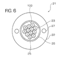
- Fig. 3 shows a cable 21 according to an embodiment of the present invention.
- the cable 21 has an outer sheath 22 in which buffer tubes 23 are provided.
- Each of the buffer tubes 23 surrounds a plurality of loosely provided optical fibers 25.
- the buffer tubes 23 are coupled together to prevent slippage between adjacent buffer tubes 23.
- the buffer tubes 23 form an undivided, compact core unit 100.
- the buffer tube coupling may be achieved by a variety of means.
- an adhesive 30 may bond the buffer tubes 23 together.
- the adhesive 30 may be a hot-melt adhesive or an ultraviolet light curable adhesive. Such adhesives are well known in the relevant art and therefore a detailed discussion of the same will not be provided.
- the bond strength of the adhesive 30 is less than the tear strength of the buffer tubes 23. Accordingly, when accessing the optical fibers 25 (to perform fiber splicing for example), a selected buffer tube 23 may be easily uncoupled from the core unit 100.
- the cable 21 does not include an anchoring element located at the center of the cavity. This feature advantageously provides the present cable design with improved cable efficiency. That is, the present cable design has an increased fiber count per cable volume as compared to that of conventional cable designs.
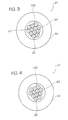
- Fig. 4 shows a second embodiment of the invention.
- the second embodiment has the same elements as those shown in Fig. 3.
- the embodiment in Fig. 4 does not use an adhesive to couple together the buffer tubes 23. Instead, the buffer tubes 23 are fused together to form the core unit 100.
- Fusion may be achieved thermally, chemically, or by a combination of the two approaches.
- the buffer tubes 23 are heated over their melting temperature and pressed together so that the contacting surfaces of adjacent buffer tubes 23 become bonded together.
- the heating of the buffer tubes occurs just after an extrusion step to achieve the desired thermal fusion effect.
- a chemical may be provided on the buffer tubes to achieve a chemical fusion effect, i.e ., a chemical bond between the contacting surfaces of adjacent buffer tubes 23.
- the cable 21 has the same elements as the first and second embodiments.
- the buffer tubes 23 are not held together by an adhesive (first embodiment) or fusion boding (second embodiment).
- the buffer tubes 23 have high friction, outer surfaces.
- the outer surfaces may be textured.
- a thread may wrap around and hold the buffer tubes 23 in contact with each other. The high friction surfaces and the thread cooperate to prevent slippage between adjacent buffer tubes 23.
- the buffer tubes 23 and the thread form the core unit 100.
- the buffer tubes 23 are mechanically coupled together.
- one buffer tube 23 may have a grooved outer surface that meshes with a complementary shaped outer surface of an adjacent buffer tube 23.
- the grooves in the outer surfaces of the buffer tubes 23 may function to prevent slippage between adjacent buffer tubes, as well as hold the buffer tubes 23 together in an undivided, compact core unit 100.
- the grooved outer surfaces may be provided in conjunction with another coupling means, such as an adhesive (first embodiment) or fusion bonding (second embodiment).
- Fig. 5(A) shows the cable 21 at a relatively high temperature
- Fig. 5(B) shows the cable 21 at a relatively low temperature
- Figs. 5(A) and 5(B) show the core unit 100 generally, and the details of only one buffer tube 23 and the optical fibers 5 therein.
- a point 200 exists along the length of the cable 21 at which the inner surface of the outer sheath 22 frictionally engages with the outer surface of the illustrated buffer tube 23' ("the contacting buffer tube").
- the buffer tubes 23, 23' may contract (or deform) slightly in a longitudinal direction 15. But the buffer tube contraction is counteracted by the stiffness of the optical fibers 5, or altogether avoided due to the free space within the buffer tubes 23, 23'.
- the outer sheath 22 also contracts longitudinally. Due to its bulkiness, the outer sheath 22 contracts more severely and with more force.
- the core unit 100 does not bend/buckle. Instead, the core unit 100 has enough buckling resistance to overcome the frictional engagement at the contact point 200. Consequently, at the contact point 200, the inner surface of the outer sheath 22 slides across the outer surface of the contacting buffer tube 23'. That is, the initial contact surface 201 of the outer sheath 22 may move relative to the core unit 100 a certain distance d.
- the core unit 100 has an increased buckling resistance compared to a single, uncoupled buffer tube 23.
- This increased buckling resistance may be attributable to at least the following factors.
- the stiffness of all of the optical fibers 25 (not just the optical fibers in the contacting buffer tube 23') counteract the transverse forces applied by the outer sheath 22.
- the buckling resistance of the core unit 100 needs to be increased enough to overcome the frictional engagement at the contact point 200 between the outer sheath 22 and the contacting buffer tube 23'.
- the core unit 100 does not buckle. This action will eliminate or greatly reduce the localized sharp bends or buckle of the buffer tubes at the contact positions. Accordingly, the contacting buffer tube 23' does not engage with and bend/buckle the optical fibers 5 therein. In this way, the present cable design significantly reduces the micro bending phenomenon (and the associated increased signal attenuation) that would otherwise occur due to temperature fluctuations.
- conventional materials may be used to fabricate the cable elements.
- Conventional materials include, but are not limited to polyethylene, polypropylene, polyvinyl chloride, polyester, polyamide or copolymer or polymer blend of the above. Such materials are well known in the relevant art, and therefore a detailed description of the same will not be provided.
- New materials may also be formulated to generate fusion between the buffer tubes. The characteristics of such new materials will include, but not be limited to, lower surface smoothness and low surface thermal stability.
- the cable 21 may include an armoring 26 provided in the outer sheath 22, or strength members 27 in the outer sheath 22.
- the cable 21 may also include yarns, tapes, and water swellable elements. All of these additional cable elements are well known in the art and therefore a detailed description of the same will not be provided.
- a cable according to the present invention provides significant advantages. Namely, the present cable has increase performance during temperature variations, without compromising compactness.
Landscapes
- Physics & Mathematics (AREA)
- General Physics & Mathematics (AREA)
- Optics & Photonics (AREA)
- Insulated Conductors (AREA)
- Light Guides In General And Applications Therefor (AREA)
- Communication Cables (AREA)
- Measuring Temperature Or Quantity Of Heat (AREA)
Abstract
Description
Claims (15)
- A cable (21) comprising:wherein said buffer tubes are coupled together to prevent slippage between said buffer tubes.an outer sheath (22) with a central cavity that does not have an anchoring element located at a center of said central cavity;a plurality of buffer tubes (23) provided in said central cavity; andat least one optical fiber (25) provided in each of said buffer tubes,
- The cable according to claim 1, further comprising:an adhesive (30) coupling together said buffer tubes.
- The cable according to claim 2, wherein said adhesive is a hot-melt adhesive.
- The cable according to claim 2, wherein said adhesive is an ultraviolet light curable adhesive.
- The cable according to claim 2, 3 or 4, wherein a bond strength of said adhesive is less than a tear strength of said buffer tubes.
- The cable according to claim 1, wherein said buffer tubes are fused together.
- The cable according to claim 1, further comprising:an armoring (26) provided in said outer sheath and surrounding said buffer tubes.
- The cable according to claim 1, wherein said at least one optical fiber (25) is loosely provided in each of said buffer tubes (23).
- A method of making a cable (21), the method comprising the steps of:positioning at least one optical fiber (25) in each of a plurality of buffer tubes (23);coupling the buffer tubes together to prevent slippage between the buffer tubes; andproviding an outer sheath (22) over the coupled together buffer tubes, such that a cavity of the outer sheath does not have an anchoring element located at a center of the cavity.
- The method according to claim 9, wherein the coupling step comprises providing an adhesive (30) on the buffer tubes to couple together the buffer tubes.
- The method according to claim 10, wherein the adhesive is a hot-melt adhesive.
- The method according to claim 10, wherein the adhesive is an ultraviolet light curable adhesive.
- The method according to claim 10, 11 or 12, wherein the adhesive has a bond strength that is less than a tear strength of the buffer tubes.
- The method according to claim 9, wherein the coupling step comprises fusing the buffer tubes together.
- The method according to claim 9, further comprising the step of:providing an armoring (26) in the outer sheath to surround the buffer tubes.
Applications Claiming Priority (4)
| Application Number | Priority Date | Filing Date | Title |
|---|---|---|---|
| US590167 | 1990-09-28 | ||
| US15224799P | 1999-09-03 | 1999-09-03 | |
| US152247P | 1999-09-03 | ||
| US09/590,167 US6504980B1 (en) | 1999-09-03 | 2000-06-09 | Highly compact optical fiber communications cable |
Publications (3)
| Publication Number | Publication Date |
|---|---|
| EP1168023A2 true EP1168023A2 (en) | 2002-01-02 |
| EP1168023A3 EP1168023A3 (en) | 2004-03-31 |
| EP1168023B1 EP1168023B1 (en) | 2006-08-16 |
Family
ID=26849383
Family Applications (1)
| Application Number | Title | Priority Date | Filing Date |
|---|---|---|---|
| EP00202970A Expired - Lifetime EP1168023B1 (en) | 1999-09-03 | 2000-08-28 | High-count optical fiber communication cable |
Country Status (6)
| Country | Link |
|---|---|
| US (1) | US6504980B1 (en) |
| EP (1) | EP1168023B1 (en) |
| CN (1) | CN1320381C (en) |
| AT (1) | ATE336734T1 (en) |
| DE (1) | DE60030098T2 (en) |
| ES (1) | ES2269064T3 (en) |
Cited By (2)
| Publication number | Priority date | Publication date | Assignee | Title |
|---|---|---|---|---|
| EP1591814A1 (en) * | 2004-04-28 | 2005-11-02 | Furukawa Electric North America Inc. | High count optical fiber cable |
| WO2017160666A1 (en) * | 2016-03-15 | 2017-09-21 | Commscope, Inc. Of North Carolina | Multi-member cable with improved mid-span access |
Families Citing this family (9)
| Publication number | Priority date | Publication date | Assignee | Title |
|---|---|---|---|---|
| KR100442605B1 (en) | 2002-03-04 | 2004-08-02 | 삼성전자주식회사 | Lightweight optical cable |
| US7421169B2 (en) * | 2003-06-20 | 2008-09-02 | Fujikura Ltd. | Optical fiber cable |
| US7515795B2 (en) * | 2005-07-20 | 2009-04-07 | Draka Comteq B.V. | Water-swellable tape, adhesive-backed for coupling when used inside a buffer tube |
| US7567739B2 (en) * | 2007-01-31 | 2009-07-28 | Draka Comteq B.V. | Fiber optic cable having a water-swellable element |
| US7599589B2 (en) * | 2005-07-20 | 2009-10-06 | Draka Comteq B.V. | Gel-free buffer tube with adhesively coupled optical element |
| US8682123B2 (en) | 2010-07-15 | 2014-03-25 | Draka Comteq, B.V. | Adhesively coupled optical fibers and enclosing tape |
| CN103604382A (en) * | 2013-11-01 | 2014-02-26 | 河海大学 | Bellows-distributed optical fiber measuring sensor |
| US10809475B2 (en) | 2014-03-18 | 2020-10-20 | Corning Optical Communications LLC | Jacket for a fiber optic cable |
| AT518541B1 (en) * | 2016-05-09 | 2017-11-15 | Teufelberger Seil Ges M B H | steel cable |
Family Cites Families (14)
| Publication number | Priority date | Publication date | Assignee | Title |
|---|---|---|---|---|
| JPS57141606A (en) * | 1981-02-18 | 1982-09-02 | Furukawa Electric Co Ltd:The | Optical communication cable |
| US5013127A (en) * | 1990-04-26 | 1991-05-07 | Siecor Corporation | Flexible fiber optic distribution cable |
| FR2665266B1 (en) * | 1990-07-27 | 1993-07-30 | Silec Liaisons Elec | FIBER OPTIC TELECOMMUNICATION CABLE. |
| US5325457A (en) * | 1991-09-20 | 1994-06-28 | Bottoms Jack Jr | Field protected self-supporting fiber optic cable |
| US5224192A (en) * | 1992-04-13 | 1993-06-29 | Siecor Corporation | Cable with light waveguide tubes in a matrix |
| GB2271859B (en) | 1992-10-21 | 1995-10-18 | Northern Telecom Ltd | Optical fibre cable comprising stack of ribbon fibre elements |
| CN2171878Y (en) * | 1993-07-09 | 1994-07-13 | 深圳光通发展有限公司 | Pipe type light cable with multiple metal wire flat armoured centre bunch |
| US5425121A (en) * | 1994-02-02 | 1995-06-13 | Siecor Corporation | Cable assembly for use with opto-electronic equipment enclosures |
| FR2725041B1 (en) | 1994-09-23 | 1996-11-22 | Alcatel Cable | OPTICAL FIBER CABLE |
| DE19517118A1 (en) * | 1995-05-10 | 1996-11-14 | Siemens Ag | Optical fibre transmission element for optical or electrical cable |
| US5970196A (en) * | 1997-09-22 | 1999-10-19 | Siecor Corporation | Fiber optic protective member with removable section to facilitate separation thereof |
| JPH11142702A (en) * | 1997-11-13 | 1999-05-28 | Sumitomo Electric Ind Ltd | Optical cable and installation method thereof |
| US6226431B1 (en) * | 1999-06-29 | 2001-05-01 | Lucent Technology Inc. | Optical fiber cable |
| US6584251B1 (en) * | 2000-05-23 | 2003-06-24 | Alcatel | Solid stranding flextube unit |
-
2000
- 2000-06-09 US US09/590,167 patent/US6504980B1/en not_active Expired - Lifetime
- 2000-08-28 CN CNB001262025A patent/CN1320381C/en not_active Expired - Fee Related
- 2000-08-28 AT AT00202970T patent/ATE336734T1/en not_active IP Right Cessation
- 2000-08-28 DE DE60030098T patent/DE60030098T2/en not_active Expired - Lifetime
- 2000-08-28 EP EP00202970A patent/EP1168023B1/en not_active Expired - Lifetime
- 2000-08-28 ES ES00202970T patent/ES2269064T3/en not_active Expired - Lifetime
Cited By (4)
| Publication number | Priority date | Publication date | Assignee | Title |
|---|---|---|---|---|
| EP1591814A1 (en) * | 2004-04-28 | 2005-11-02 | Furukawa Electric North America Inc. | High count optical fiber cable |
| US6973246B2 (en) | 2004-04-28 | 2005-12-06 | Furukawa Electric North America, Inc. | High count optical fiber cable |
| WO2017160666A1 (en) * | 2016-03-15 | 2017-09-21 | Commscope, Inc. Of North Carolina | Multi-member cable with improved mid-span access |
| US10600533B2 (en) | 2016-03-15 | 2020-03-24 | Commscope, Inc. Of North Carolina | Multi-member cable with improved mid-span access |
Also Published As
| Publication number | Publication date |
|---|---|
| ATE336734T1 (en) | 2006-09-15 |
| ES2269064T3 (en) | 2007-04-01 |
| EP1168023A3 (en) | 2004-03-31 |
| CN1289056A (en) | 2001-03-28 |
| DE60030098D1 (en) | 2006-09-28 |
| CN1320381C (en) | 2007-06-06 |
| EP1168023B1 (en) | 2006-08-16 |
| DE60030098T2 (en) | 2007-02-15 |
| US6504980B1 (en) | 2003-01-07 |
Similar Documents
| Publication | Publication Date | Title |
|---|---|---|
| US6504980B1 (en) | Highly compact optical fiber communications cable | |
| US8944702B2 (en) | Fiber optic connector with fiber take-up region | |
| US6542674B1 (en) | Fiber optic cables with strength members | |
| AU2015230803B2 (en) | Fiber optic connector, connection system and adapter | |
| AU654044B2 (en) | Multiple optical fiber splice | |
| TW294789B (en) | ||
| JP5235125B2 (en) | Optical fiber tape and optical fiber cable | |
| JP2010008923A (en) | Fiber optic cable | |
| EP0602105A1 (en) | Multiple optical fiber splice | |
| WO2005036232A3 (en) | Fiber optic cable and furcation module | |
| WO2010001663A1 (en) | Optical fiber cable and optical fiber tape | |
| JP4670218B2 (en) | Fiber optic cable | |
| EP1191375A3 (en) | Improved optical-fiber cable contaning thermally bonded fiber optic buffer tubes and fabrication process | |
| US4123138A (en) | Optical fiber connector | |
| US11971593B2 (en) | Flexible optical fiber ribbon | |
| US5799122A (en) | Multifiber optical connector | |
| JP3765688B2 (en) | Optical fiber connection mechanism, optical fiber structure, and optical fiber connection method | |
| EP4212930A1 (en) | Rollable optical fibre ribbon with intermittent bonding | |
| JP2005309367A (en) | Optical fiber connector, optical fiber connector, and optical fiber connection method | |
| JP4684130B2 (en) | Manufacturing method of mode field converter | |
| US11867947B2 (en) | Cable assembly having routable splice protectors | |
| US20240329347A1 (en) | Dual-layer sheath for an optical fiber cable | |
| US20240142720A1 (en) | Ferrule-terminated high-density optical fiber cable assembly | |
| JP3391327B2 (en) | Optical fiber fixing member and optical fiber fixing method | |
| JPS6035043Y2 (en) | Terminal structure of optical fiber connector |
Legal Events
| Date | Code | Title | Description |
|---|---|---|---|
| PUAI | Public reference made under article 153(3) epc to a published international application that has entered the european phase |
Free format text: ORIGINAL CODE: 0009012 |
|
| AK | Designated contracting states |
Kind code of ref document: A2 Designated state(s): AT BE CH CY DE DK ES FI FR GB GR IE IT LI LU MC NL PT SE |
|
| AX | Request for extension of the european patent |
Free format text: AL;LT;LV;MK;RO;SI |
|
| PUAL | Search report despatched |
Free format text: ORIGINAL CODE: 0009013 |
|
| AK | Designated contracting states |
Kind code of ref document: A3 Designated state(s): AT BE CH CY DE DK ES FI FR GB GR IE IT LI LU MC NL PT SE |
|
| AX | Request for extension of the european patent |
Extension state: AL LT LV MK RO SI |
|
| 17P | Request for examination filed |
Effective date: 20040930 |
|
| AKX | Designation fees paid |
Designated state(s): AT BE CH CY DE DK ES FI FR GB GR IE IT LI LU MC NL PT SE |
|
| 17Q | First examination report despatched |
Effective date: 20050202 |
|
| RAP1 | Party data changed (applicant data changed or rights of an application transferred) |
Owner name: DRAKA COMTEQ B.V. |
|
| GRAP | Despatch of communication of intention to grant a patent |
Free format text: ORIGINAL CODE: EPIDOSNIGR1 |
|
| GRAS | Grant fee paid |
Free format text: ORIGINAL CODE: EPIDOSNIGR3 |
|
| GRAA | (expected) grant |
Free format text: ORIGINAL CODE: 0009210 |
|
| AK | Designated contracting states |
Kind code of ref document: B1 Designated state(s): AT BE CH CY DE DK ES FI FR GB GR IE IT LI LU MC NL PT SE |
|
| PG25 | Lapsed in a contracting state [announced via postgrant information from national office to epo] |
Ref country code: AT Free format text: LAPSE BECAUSE OF FAILURE TO SUBMIT A TRANSLATION OF THE DESCRIPTION OR TO PAY THE FEE WITHIN THE PRESCRIBED TIME-LIMIT Effective date: 20060816 Ref country code: FI Free format text: LAPSE BECAUSE OF FAILURE TO SUBMIT A TRANSLATION OF THE DESCRIPTION OR TO PAY THE FEE WITHIN THE PRESCRIBED TIME-LIMIT Effective date: 20060816 Ref country code: CH Free format text: LAPSE BECAUSE OF FAILURE TO SUBMIT A TRANSLATION OF THE DESCRIPTION OR TO PAY THE FEE WITHIN THE PRESCRIBED TIME-LIMIT Effective date: 20060816 Ref country code: BE Free format text: LAPSE BECAUSE OF FAILURE TO SUBMIT A TRANSLATION OF THE DESCRIPTION OR TO PAY THE FEE WITHIN THE PRESCRIBED TIME-LIMIT Effective date: 20060816 Ref country code: LI Free format text: LAPSE BECAUSE OF FAILURE TO SUBMIT A TRANSLATION OF THE DESCRIPTION OR TO PAY THE FEE WITHIN THE PRESCRIBED TIME-LIMIT Effective date: 20060816 |
|
| REG | Reference to a national code |
Ref country code: GB Ref legal event code: FG4D |
|
| PG25 | Lapsed in a contracting state [announced via postgrant information from national office to epo] |
Ref country code: IE Free format text: LAPSE BECAUSE OF NON-PAYMENT OF DUE FEES Effective date: 20060828 |
|
| PG25 | Lapsed in a contracting state [announced via postgrant information from national office to epo] |
Ref country code: MC Free format text: LAPSE BECAUSE OF NON-PAYMENT OF DUE FEES Effective date: 20060831 |
|
| REG | Reference to a national code |
Ref country code: CH Ref legal event code: EP |
|
| REG | Reference to a national code |
Ref country code: IE Ref legal event code: FG4D |
|
| REF | Corresponds to: |
Ref document number: 60030098 Country of ref document: DE Date of ref document: 20060928 Kind code of ref document: P |
|
| REG | Reference to a national code |
Ref country code: SE Ref legal event code: TRGR |
|
| PG25 | Lapsed in a contracting state [announced via postgrant information from national office to epo] |
Ref country code: DK Free format text: LAPSE BECAUSE OF FAILURE TO SUBMIT A TRANSLATION OF THE DESCRIPTION OR TO PAY THE FEE WITHIN THE PRESCRIBED TIME-LIMIT Effective date: 20061116 |
|
| PG25 | Lapsed in a contracting state [announced via postgrant information from national office to epo] |
Ref country code: PT Free format text: LAPSE BECAUSE OF FAILURE TO SUBMIT A TRANSLATION OF THE DESCRIPTION OR TO PAY THE FEE WITHIN THE PRESCRIBED TIME-LIMIT Effective date: 20070116 |
|
| ET | Fr: translation filed | ||
| REG | Reference to a national code |
Ref country code: CH Ref legal event code: PL |
|
| REG | Reference to a national code |
Ref country code: ES Ref legal event code: FG2A Ref document number: 2269064 Country of ref document: ES Kind code of ref document: T3 |
|
| RAP2 | Party data changed (patent owner data changed or rights of a patent transferred) |
Owner name: DRAKA COMTEQ B.V. |
|
| PLBE | No opposition filed within time limit |
Free format text: ORIGINAL CODE: 0009261 |
|
| STAA | Information on the status of an ep patent application or granted ep patent |
Free format text: STATUS: NO OPPOSITION FILED WITHIN TIME LIMIT |
|
| RAP2 | Party data changed (patent owner data changed or rights of a patent transferred) |
Owner name: DRAKA COMTEQ B.V. |
|
| 26N | No opposition filed |
Effective date: 20070518 |
|
| NLT2 | Nl: modifications (of names), taken from the european patent patent bulletin |
Owner name: DRAKA COMTEQ B.V. Effective date: 20070613 |
|
| NLT2 | Nl: modifications (of names), taken from the european patent patent bulletin |
Owner name: DRAKA COMTEQ B.V. Effective date: 20070711 |
|
| PG25 | Lapsed in a contracting state [announced via postgrant information from national office to epo] |
Ref country code: GR Free format text: LAPSE BECAUSE OF FAILURE TO SUBMIT A TRANSLATION OF THE DESCRIPTION OR TO PAY THE FEE WITHIN THE PRESCRIBED TIME-LIMIT Effective date: 20061117 |
|
| PG25 | Lapsed in a contracting state [announced via postgrant information from national office to epo] |
Ref country code: LU Free format text: LAPSE BECAUSE OF NON-PAYMENT OF DUE FEES Effective date: 20060828 |
|
| PG25 | Lapsed in a contracting state [announced via postgrant information from national office to epo] |
Ref country code: CY Free format text: LAPSE BECAUSE OF FAILURE TO SUBMIT A TRANSLATION OF THE DESCRIPTION OR TO PAY THE FEE WITHIN THE PRESCRIBED TIME-LIMIT Effective date: 20060816 |
|
| REG | Reference to a national code |
Ref country code: FR Ref legal event code: PLFP Year of fee payment: 16 |
|
| PGFP | Annual fee paid to national office [announced via postgrant information from national office to epo] |
Ref country code: NL Payment date: 20150826 Year of fee payment: 16 |
|
| PGFP | Annual fee paid to national office [announced via postgrant information from national office to epo] |
Ref country code: GB Payment date: 20150827 Year of fee payment: 16 Ref country code: DE Payment date: 20150827 Year of fee payment: 16 Ref country code: ES Payment date: 20150826 Year of fee payment: 16 |
|
| PGFP | Annual fee paid to national office [announced via postgrant information from national office to epo] |
Ref country code: FR Payment date: 20150817 Year of fee payment: 16 Ref country code: SE Payment date: 20150827 Year of fee payment: 16 |
|
| PGFP | Annual fee paid to national office [announced via postgrant information from national office to epo] |
Ref country code: IT Payment date: 20150825 Year of fee payment: 16 |
|
| REG | Reference to a national code |
Ref country code: DE Ref legal event code: R119 Ref document number: 60030098 Country of ref document: DE |
|
| REG | Reference to a national code |
Ref country code: SE Ref legal event code: EUG |
|
| REG | Reference to a national code |
Ref country code: NL Ref legal event code: MM Effective date: 20160901 |
|
| GBPC | Gb: european patent ceased through non-payment of renewal fee |
Effective date: 20160828 |
|
| PG25 | Lapsed in a contracting state [announced via postgrant information from national office to epo] |
Ref country code: SE Free format text: LAPSE BECAUSE OF NON-PAYMENT OF DUE FEES Effective date: 20160829 |
|
| REG | Reference to a national code |
Ref country code: FR Ref legal event code: ST Effective date: 20170428 |
|
| PG25 | Lapsed in a contracting state [announced via postgrant information from national office to epo] |
Ref country code: NL Free format text: LAPSE BECAUSE OF NON-PAYMENT OF DUE FEES Effective date: 20160901 |
|
| PG25 | Lapsed in a contracting state [announced via postgrant information from national office to epo] |
Ref country code: GB Free format text: LAPSE BECAUSE OF NON-PAYMENT OF DUE FEES Effective date: 20160828 Ref country code: DE Free format text: LAPSE BECAUSE OF NON-PAYMENT OF DUE FEES Effective date: 20170301 Ref country code: FR Free format text: LAPSE BECAUSE OF NON-PAYMENT OF DUE FEES Effective date: 20160831 |
|
| PG25 | Lapsed in a contracting state [announced via postgrant information from national office to epo] |
Ref country code: IT Free format text: LAPSE BECAUSE OF NON-PAYMENT OF DUE FEES Effective date: 20160828 |
|
| PG25 | Lapsed in a contracting state [announced via postgrant information from national office to epo] |
Ref country code: ES Free format text: LAPSE BECAUSE OF NON-PAYMENT OF DUE FEES Effective date: 20160829 |
|
| REG | Reference to a national code |
Ref country code: ES Ref legal event code: FD2A Effective date: 20181122 |