EP1167942A2 - Spectacle lens image sensing processing apparatus and spectacle lens positioning method - Google Patents
Spectacle lens image sensing processing apparatus and spectacle lens positioning method Download PDFInfo
- Publication number
- EP1167942A2 EP1167942A2 EP01115197A EP01115197A EP1167942A2 EP 1167942 A2 EP1167942 A2 EP 1167942A2 EP 01115197 A EP01115197 A EP 01115197A EP 01115197 A EP01115197 A EP 01115197A EP 1167942 A2 EP1167942 A2 EP 1167942A2
- Authority
- EP
- European Patent Office
- Prior art keywords
- lens
- image
- processing
- spectacle lens
- convex surface
- Prior art date
- Legal status (The legal status is an assumption and is not a legal conclusion. Google has not performed a legal analysis and makes no representation as to the accuracy of the status listed.)
- Granted
Links
- 238000012545 processing Methods 0.000 title claims abstract description 433
- 238000000034 method Methods 0.000 title claims abstract description 40
- 230000003287 optical effect Effects 0.000 claims abstract description 70
- 230000000750 progressive effect Effects 0.000 claims description 64
- 238000012937 correction Methods 0.000 claims description 34
- 239000000284 extract Substances 0.000 claims description 19
- 238000003384 imaging method Methods 0.000 claims description 15
- 230000005540 biological transmission Effects 0.000 claims description 14
- 238000005259 measurement Methods 0.000 claims description 13
- 230000005484 gravity Effects 0.000 claims description 11
- 238000005286 illumination Methods 0.000 claims description 11
- 238000001514 detection method Methods 0.000 claims description 9
- 230000001678 irradiating effect Effects 0.000 claims description 5
- 230000003068 static effect Effects 0.000 description 8
- 238000000605 extraction Methods 0.000 description 6
- 239000011521 glass Substances 0.000 description 6
- 230000000903 blocking effect Effects 0.000 description 5
- 238000007688 edging Methods 0.000 description 5
- 230000000694 effects Effects 0.000 description 5
- 230000002829 reductive effect Effects 0.000 description 5
- 230000001681 protective effect Effects 0.000 description 4
- 238000010586 diagram Methods 0.000 description 3
- 238000006073 displacement reaction Methods 0.000 description 3
- 238000002372 labelling Methods 0.000 description 3
- 239000000463 material Substances 0.000 description 3
- 230000000007 visual effect Effects 0.000 description 3
- HCUOEKSZWPGJIM-YBRHCDHNSA-N (e,2e)-2-hydroxyimino-6-methoxy-4-methyl-5-nitrohex-3-enamide Chemical compound COCC([N+]([O-])=O)\C(C)=C\C(=N/O)\C(N)=O HCUOEKSZWPGJIM-YBRHCDHNSA-N 0.000 description 2
- 238000012935 Averaging Methods 0.000 description 2
- 238000000149 argon plasma sintering Methods 0.000 description 2
- 238000013461 design Methods 0.000 description 2
- 239000000428 dust Substances 0.000 description 2
- 230000001747 exhibiting effect Effects 0.000 description 2
- 238000009499 grossing Methods 0.000 description 2
- 230000012447 hatching Effects 0.000 description 2
- 238000004519 manufacturing process Methods 0.000 description 2
- 239000003550 marker Substances 0.000 description 2
- 230000001154 acute effect Effects 0.000 description 1
- 239000000853 adhesive Substances 0.000 description 1
- 230000001070 adhesive effect Effects 0.000 description 1
- XAGFODPZIPBFFR-UHFFFAOYSA-N aluminium Chemical compound [Al] XAGFODPZIPBFFR-UHFFFAOYSA-N 0.000 description 1
- 238000004364 calculation method Methods 0.000 description 1
- 238000006243 chemical reaction Methods 0.000 description 1
- 239000011248 coating agent Substances 0.000 description 1
- 238000000576 coating method Methods 0.000 description 1
- 239000000470 constituent Substances 0.000 description 1
- 238000007796 conventional method Methods 0.000 description 1
- 230000006866 deterioration Effects 0.000 description 1
- 238000011161 development Methods 0.000 description 1
- 230000018109 developmental process Effects 0.000 description 1
- 239000005357 flat glass Substances 0.000 description 1
- 239000005337 ground glass Substances 0.000 description 1
- 229910052751 metal Inorganic materials 0.000 description 1
- 239000002184 metal Substances 0.000 description 1
- 238000000465 moulding Methods 0.000 description 1
- 230000036961 partial effect Effects 0.000 description 1
- 239000002245 particle Substances 0.000 description 1
- 230000000737 periodic effect Effects 0.000 description 1
- 239000000843 powder Substances 0.000 description 1
- 238000007781 pre-processing Methods 0.000 description 1
- 230000002441 reversible effect Effects 0.000 description 1
- 239000002689 soil Substances 0.000 description 1
- 229910001220 stainless steel Inorganic materials 0.000 description 1
- 239000010935 stainless steel Substances 0.000 description 1
- 239000004575 stone Substances 0.000 description 1
- 238000004381 surface treatment Methods 0.000 description 1
- 229920003002 synthetic resin Polymers 0.000 description 1
- 239000000057 synthetic resin Substances 0.000 description 1
- 238000002834 transmittance Methods 0.000 description 1
Images


Classifications
-
- G—PHYSICS
- G01—MEASURING; TESTING
- G01M—TESTING STATIC OR DYNAMIC BALANCE OF MACHINES OR STRUCTURES; TESTING OF STRUCTURES OR APPARATUS, NOT OTHERWISE PROVIDED FOR
- G01M11/00—Testing of optical apparatus; Testing structures by optical methods not otherwise provided for
- G01M11/02—Testing optical properties
- G01M11/0207—Details of measuring devices
- G01M11/0214—Details of devices holding the object to be tested
-
- G—PHYSICS
- G01—MEASURING; TESTING
- G01M—TESTING STATIC OR DYNAMIC BALANCE OF MACHINES OR STRUCTURES; TESTING OF STRUCTURES OR APPARATUS, NOT OTHERWISE PROVIDED FOR
- G01M11/00—Testing of optical apparatus; Testing structures by optical methods not otherwise provided for
- G01M11/02—Testing optical properties
- G01M11/0207—Details of measuring devices
-
- B—PERFORMING OPERATIONS; TRANSPORTING
- B29—WORKING OF PLASTICS; WORKING OF SUBSTANCES IN A PLASTIC STATE IN GENERAL
- B29D—PRODUCING PARTICULAR ARTICLES FROM PLASTICS OR FROM SUBSTANCES IN A PLASTIC STATE
- B29D11/00—Producing optical elements, e.g. lenses or prisms
- B29D11/00951—Measuring, controlling or regulating
- B29D11/0098—Inspecting lenses
Definitions
- the present invention relates to a spectacle lens image sensing processing apparatus and spectacle lens positioning method which can be suitably used for a layout blocker for determining a lens processing center or the like for edging of a spectacle lens and mounting a processing jig at the processing center.
- the optical characteristics of the prescription lens e.g., the optical center, geometrical center, diameter, eyepoint position, lens power, and cylinder axis are checked in the pre-process, and a processing center, the mounting angle of a processing jig (to be generally called a lens holder) with respect to the lens, and the like (optical layout) are determined from the lens information, lens frame shape data, and prescription data about a wearer.
- the center of the lens holder is positioned to the processing center of the lens, and the lens holder is mounted on the lens surface (blocking).
- the processing center of the lens coincides with the eyepoint position of the lens.
- the rim of the lens is edged by a grind stone or cutter to match the pupil center (eyepoint) of a wearer to the eyepoint position of the lens, thereby processing the lens into a shape conforming to the shape of an eyeglass frame.
- an optical layout procedure and blocking for a lens which are included in the pre-process for edging of the lens, are manually performed by an operator using specialized devices.
- the lens power of a lens to be examined is measured by a power measuring device called a lens meter.
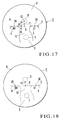
- micro engraved marks 3A and 3B are formed at reference positions spaced apart from a geometrical center O by a predetermined distance, as shown in Fig. 17. Since the lens 1 is designed to derive the geometrical center O, the optical centers of distance and near portions, an eyepoint 11, and the like from the positions of these micro engraved marks 3A and 3B, the position of the eyepoint 11 is detected from the positions of these micro engraved marks 3A and 3B, and a lens holder is mounted at the position of the eyepoint 11.
- Fig. 18 shows another example of the progressive multifocal lens 1.
- the progressive multifocal lens 1 shown in Fig. 18 is a right-eye lens whose micro engraved marks 3A and 3B both are circular.
- the marks are generally detected by a visual check or optically.
- the micro engraved marks 3A and 3B are detected by holding the lens to light from a light source such as a fluorescent lamp, and the detected position is marked with a marker.
- the position of the eyepoint 11 is determined by using a sheet called a remark chart for a progressive multifocal lens.
- the remark chart lists actual-size images of progressive multifocal lenses by lens type, showing the positions of micro engraved marks, geometrical centers, distance power measuring portions, near power measuring portions, the positions of eyepoints, and the like.
- the lens 1 on which the positions of the micro engraved marks 3A and 3B are marked is placed on this chart.
- the lens 1 is placed on an image of the same type of lens as the lens to be examined of the lenses listed on the remark chart, and the positions of the micro engraved marks 3A and 3B marked on the lens 1 are matched to the positions of the micro engraved marks shown on the remark chart.
- the position of the eyepoint shown on the remark chart is indicated on the convex surface of the lens 1 with a marker. Thereafter, the center of the lens holder is positioned to the marked eyepoint 11, and the lens holder is mounted.
- a spectacle lens is positioned on the basis of the positional relationship and positional information of positioning marks (micro engraved marks, addition power) formed on the convex surface of the spectacle lens.
- An illumination adjustment lens is interposed between an illumination unit and the spectacle lens to irradiate the spectacle lens with light emitted from the illumination unit from the concave surface side through the illumination adjustment lens, and an image on the concave surface is sensed by an image input means such as a CCD.
- This sensed image is processed by an image processing unit to detect the positioning marks.
- a computation is then made to establish a predetermined positional relationship between the horizontal reference line of the spectacle lens and the position of an optical center on the basis of the positional relationship and positional information of these marks.
- the spectacle lens is positioned on the basis of the computation result.
- the lens to be examined is a multifocal lens (in general, a bi-focal lens)
- no micro engraved marks are formed on the lens unlike the progressive multifocal lens 1 described above.
- this lens is designed to obtain the positions of an geometrical center O and eyepoint 16 with reference to an upper rim 17 of a segment 13B. Therefore, when the position of the eyepoint 16 is to be detected by a visual check, the position of the eyepoint 16 can be determined by using a remark chart for multifocal lenses as in the case of the progressive multifocal lens 1 described above. When this position is to be optically detected, the lens positioning method and apparatus disclosed in the prior art can be used.
- the apparatus is required to have a device for sensing an image of the convex surface of a lens, detecting micro engraved marks or the upper rim of a segment by performing image processing for the sensed image, and detecting the optical characteristics (the position of a geometrical center, the position of an eyepoint, and the like) of the lens from these pieces of positional information as well as a lens meter for measuring a lens power.
- Lens meters have been known, and, for example, the lens meters disclosed in Japanese Patent Laid-Open Nos. 49-122355 and 60-17355 and Japanese Patent Publication No. 8-20334 can be used.
- the positioning method and apparatus disclosed in the above reference can be used.
- these positioning method and apparatus are difficult to apply to a lens having an astigmatic power, and hence are not practical.
- the light source and image sensing means are respectively arranged on the convex surface side and concave surface side of a lens, if the lens has an astigmatic power, the image sensed by the image sensing means distorts due to the cylinder axis, and image processing demands complicated correction, regardless of whether the lens is a single-focus lens, multifocal lens, or progressive multifocal lens.
- the progressive multifocal lens 1 is image-sensed after it is optically magnified for the following reason. If the lens is image-sensed without optically magnifying it, the resultant image becomes as small as several pixels. In using template matching, however, an image having a size of at least 10 x 10 pixels is required. According to this method using template matching, the progressive multifocal lens 1 and lens holder can be accurately positioned.
- the spectacle lens positioning apparatus disclosed in Japanese Patent Laid-Open No. 6-79600 is known.
- This positioning apparatus is designed to image-sense the multifocal lens 13 to be processed by using a video camera and display the sensed contour image of the segment 13B of the multifocal lens 13 on the screen of a TV monitor.
- the apparatus is also designed to calculate the contour image data of the segment 13B from the processing information about the multifocal lens 13 which is stored in advance and display the calculated contour image as a reference image on the screen of the TV monitor.
- An operator moves a slide table, on which the multifocal lens 13 is mounted, to superimpose on the reference image the real image of the contour line of the segment 13B displayed on the screen of the TV monitor, thereby positioning the multifocal lens 13 to the normal position.
- a pad printer of a marking unit transfers a cross-shaped mark corresponding to a processing reference line onto a predetermined position on the multifocal lens 13.
- the positioning apparatus disclosed in Japanese Patent Laid-Open No. 6-79600 is designed to position the multifocal lens 13 while watching the TV monitor instead of a remark chart.
- a spectacle lens image sensing processing apparatus for irradiating a convex surface of a lens to be examined with light from a light source, projecting an image of the convex surface onto image display means placed on a concave surface side of the lens, sensing the image of the convex surface, projected on the image display means, by using an image sensing unit, and performing image processing for the image of the convex surface sensed by the image sensing unit by using an image processing unit, thereby detecting an optical characteristic of the lens, wherein the image sensing unit is placed together with the light source on the convex surface side of the lens, the image display means is formed by a reflection screen, and the image of the convex surface of the lens is reflected by the reflection screen to return to the convex surface side of the lens, thereby forming the image on the image sensing unit.
- Fig. 1 shows a spectacle lens image sensing processing apparatus according to the first embodiment of the present invention.
- a spectacle lens image sensing processing apparatus (to be referred to as an image sensing processing apparatus hereinafter) 30 can detect the optical characteristics (the position of an eyepoint, geometrical center, and the like) of a lens A to be examined, which includes two types of lenses, i.e., a progressive multifocal lens and multifocal lens.
- a progressive multifocal lens and multifocal lens will be described first with reference to Figs. 17, 18, and 19.
- reference numeral 1 denotes an uncut plastic progressive multifocal lens; 2, a horizontal reference line passing through a geometrical center O; and 3A and 3B, micro engraved marks formed at two positions spaced apart from the geometrical center ⁇ on the horizontal reference line 2 by an equal distance (e.g., 17 mm).
- These micro engraved marks 3A and 3B are indicated by identical small circles or identical small circles and characters.
- a numeral 4 representing the addition power (the difference between the refractive power at the outer vertex of a distance portion and the refractive power at the outer vertex of a near portion) of the lens 1 and an identification mark 5 representing the type of lens are respectively indicated below the marks in the form of small projections.
- the numeral 4 representing the addition power is indicated by three-digit numeral (e.g., 300) below the micro engraved mark located on the ear side of a wearer.
- the lens can therefore be identified as a left-eye lens or right-eye lens by detecting whether this three-digit numeral is indicated below the left or right mark.
- the lens is a right-eye lens
- the left micro engraved mark 3A and right micro engraved mark B are indicated in small circle " ⁇ " and Roman letter "H”.
- the micro engraved marks 3A and 3B, the numeral 4 representing the addition power, and the identification mark 5 are formed in the shape of small projections (e.g., about 2 to 4 ⁇ m) on the convex surface of the lens in the molding process.
- Reference numeral 6 denotes a distance power measuring portion; 7, a near power measuring portion; 8, a portion for seeing distant objects (distance portion); 9, a portion for seeing nearby objects (near portion); 10, a portion whose power continuously changes (progressive portion); and 11, an eyepoint.
- the positions of the distance power measuring portion 6, near power measuring portion 7, and eyepoint 11 vary depending on the design of a lens. However, predetermined reference positions separated from the geometrical center O are fixed.
- the eyepoint 11 is fixed at a position separated upward from the geometrical center O by a predetermined distance d1 (e.g., 2 mm), and a distance center 12 is fixed at a position separated upward from the position of the eyepoint 11 by a predetermined distance d2 (e.g., 4 mm). Therefore, the position of the geometrical center O or eyepoint 11 can be obtained by inputting images of the micro engraved marks 3A and 3B and calculating their position coordinates by image processing.
- d1 e.g., 2 mm
- a distance center 12 is fixed at a position separated upward from the position of the eyepoint 11 by a predetermined distance d2 (e.g., 4 mm). Therefore, the position of the geometrical center O or eyepoint 11 can be obtained by inputting images of the micro engraved marks 3A and 3B and calculating their position coordinates by image processing.
- the progressive multifocal lens 1 shown in Fig. 18 is a right-eye lens whose micro engraved marks 3A and 3B both are circular.
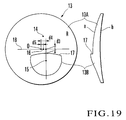
- Fig. 19 shows a right-eye multifocal (bi-focal) lens 13 made of a plastic material.
- Reference numeral 13A denotes a main lens; 13B, a segment; 14, a distance power measuring portion; 15, the center of a near power measuring portion; O, a geometrical center; and 16, an eyepoint position.
- the segment 13B is formed on the surface of the main lens 13A so as to protrude in the form of a wedge in side view.
- An upper rim 17 of the segment 13B is separated downward from a horizontal reference line 18 passing through the geometrical center O by a predetermined distance d3 (e.g., 5 mm).
- the segment 13B is formed such that the center 15 of the near power measuring portion is shifted rightward from the geometrical center O by a predetermined distance d4 (e.g., 5 mm).
- the position of the eyepoint 16 is fixed at a position shifted from the geometrical center O toward the segment 13B on the horizontal reference line 18 by a predetermined distance d5 (e.g., 2.5 mm). If, therefore, an image of the segment 13B is sensed, and the coordinates of the middle position of the upper rim 17 are calculated by image processing, the positions of the geometrical center O and eyepoint 16 can be obtained.
- the upper rim 17 of the segment 13B corresponds to the micro engraved marks 3A, 3B, and 3C of the progressive multifocal lens 1.
- the lens can be identified as a left- or right-eye lens by detecting which side the geometrical center O of the segment 13B is shifted.
- the image sensing processing apparatus 30 includes a progressive multifocal lens light source 31, which is placed on the convex surface a side of the lens A, and a condenser lens 32, a stop 33, and a half mirror 34 which are placed in the optical path between the light source 31 and the lens A.
- the light source 31 is used when the lens A is the progressive multifocal lens 1 shown in Fig. 17.
- an LED for emitting red light with a short wavelength is used as this light source 31 to obtain sharp images of the micro engraved marks 3A, 3B, and 3C, numeral 4 representing the addition power, and identification mark 5.
- the half mirror 34 a mirror whose transmittance/reflectance ratio is 7 : 3 is used.
- the image sensing processing apparatus 30 also includes a lens holder 37, condenser lens 38, imaging lens 39, reflection screen (image display means) 40, multifocal lens light source 41, and the like which are arranged on the concave surface b side of the lens A.
- the lens holder 37 chucks/fixes the central portion of the concave surface of the lens A and includes a lens support cylinder 42 having two open ends.
- the central portion of the concave surface of the lens A is chucked/fixed on the upper surface of the lens support cylinder 42 by evacuating the interior of the lens support cylinder 42 using a vacuum pump 43.
- the outer diameter of the lens support cylinder 42 is small enough (e.g., 8 mm) to prevent interference with projection of the micro engraved marks 3A, 3B, and 3C, numeral 4 representing the addition power, and identification mark 5 of the progressive multifocal lens 1 and the projection of the segment 13B of the multifocal lens 13.
- the condenser lens 38 focuses an image of the convex surface of the lens A and includes first and second convex lenses 38a and 38b arranged in a lens barrel 44.
- the enclosed space surrounded by the two convex lenses 38a and 38b and lens barrel 44 forms an exhaust chamber 45, which is connected to the vacuum pump 43.
- a communicating hole 46 is formed in the central portion of the convex lens 38a to make the interior of the lens support cylinder 42 communicate with the exhaust chamber 45.
- the imaging lens 39 is formed by a convex lens, which forms the image of the convex surface of the lens A, which is focused by the condenser lens 38, on the reflection screen 40 in substantially the same size as that of the focused image. Note that this imaging lens 39 is used as a light-sending lens when the lens A is the multifocal lens 13.
- a reflecting sheet is bonded to the reflection screen 40.
- This sheet is formed by coating the surface of a base member with a fine powder such as a glass or aluminum powder as particles that increase the reflectance and improve the light scattering effect.
- the reflection screen 40 is rotated at a high speed (e.g., 3,400 rpm) by a motor 47 to reflect the image of the convex surface of the lens A, thereby making the surface brightness and background uniform. This increases the contrast between a micro engraved mark portion and an non-micro engraved mark portion.
- the image of the concave surface of the lens A returns to the convex surface a side of the lens A through the initial optical path and is reflected by the half mirror 34 to be formed on the light-receiving surface of an image sensing unit 48.
- This image is input to an image processing unit 49 such as a CCD to be subjected to image processing.
- the multifocal lens light source 41 is used for image-sensing of the multifocal lens 13 shown in Fig. 19. Red LEDs are used for this light source. For example, eight LEDs are arranged at an equal interval in the circumferential direction below the imaging lens 39 near its outer circumference. Light from the light source 41 is reflected by the reflection screen 40, passes through the imaging lens 39 and condenser lens 38, and strikes the concave surface b of the lens A. An image of the convex surface of the lens A is then reflected by the half mirror 34 to be formed on the image sensing unit 48. In image-sensing the progressive multifocal lens 1, a focus correction lens 50 is inserted between the half mirror 34 and the image sensing unit 48.
- the reason why the multifocal lens 13 is irradiated by the light source 41 from the concave surface b side is that the upper rim 17 of the segment 13B can be projected more clearly than when the multifocal lens 13 is irradiated from the convex surface a side.
- the lens A is the progressive multifocal lens 1 shown in Fig. 17, the lens A is mounted on the upper surface of the lens support cylinder 42 with the convex surface a facing up.
- the interior of the lens support cylinder 42 and exhaust chamber 45 are then evacuated by the vacuum pump 43 to chuck/fix the lens A on the opening portion of the upper surface of the lens support cylinder 42.
- the light source 31 is turned on to irradiate the convex surface a of the lens A, and an image of the convex surface on which the micro engraved marks 3A, 3B, and 3C, numeral 4 representing the addition power, and identification mark 5 are indicated is focused by the condenser lens 38 and projected on the reflection screen 40 by the imaging lens 39.
- the image projected on the reflection screen 40 is reflected by the reflection screen 40 to return to the convex surface a side of the lens A through the initial optical path.
- the image is then formed on the image sensing unit 48 through the half mirror 34.
- the image processing unit 49 receives this image and performs image processing to detect the micro engraved marks 3A, 3B, 3C, numeral 4 representing the addition power, and identification mark 5 and calculate the positions of the micro engraved marks 3A and 3B.
- the image processing unit 49 also identifies the lens as a left- or right-eye lens on the basis of the position of the numeral 4 representing the addition power, and detects the type of lens from the identification mark 5.
- the image processing unit 49 obtains the positions of the geometrical center O of the lens and eyepoint 11 and the like from the positional information of the micro engraved marks 3A, 3B, and 3C by arithmetic processing.
- the mounting angle of the lens holder around the axis and the like with respect to the processing center and lens are determined from the obtained lens information, lens frame shape data, and the prescription data of a wearer.
- the lens A is the multifocal lens 13 shown in Fig. 19
- the lens A is placed on the upper surface of the lens support cylinder 42, and the lens support cylinder 42 and exhaust chamber 45 are evacuated by the vacuum pump 43 to chuck/fix the lens A on the lens support cylinder 42, as in the above case of the progressive multifocal lens 1.
- the multifocal lens light source 41 is used instead of the progressive multifocal lens light source 31.
- the focus correction lens 50 is inserted in the optical path between the half mirror 34 and the image sensing unit 48, and the image sensing unit 48 is focused on the convex surface a of the lens A.
- the emitted light is reflected by the reflection screen 40, passes through the imaging lens 39 and condenser lens 38, and strikes the multifocal lens 13 from the concave surface b side, thereby guiding an image of the upper rim 17 of the segment 13B, formed on the convex surface a side, to the image sensing unit 48 through the half mirror 34.
- This image is input to the image processing unit 49 and subjected to image processing, thereby detecting the upper rim 17 and calculating its position.
- the positions of the geometrical center O and eyepoint 16 and the like are calculated from the positional information of the upper rim 17.
- the mounting angle of the lens holder around the axis and the like with respect to the processing center and lens are determined from the obtained lens information, lens frame shape data, and the prescription data of a wearer.
- the progressive multifocal lens light source 31 and image sensing unit 48 are arranged on the convex surface a side of the lens A.
- the lens A is the progressive multifocal lens 1
- an image of the convex surface of the lens is sensed
- the image of the convex surface of the lens A is projected on the reflection screen 40 placed on the concave surface b side, and the image reflected by the reflection screen 40 is returned to the convex surface a side of the lens A to be guided to the image sensing unit 48.
- the lens A has an astigmatic power, no image distortion is caused by the cylinder axis, and a good image can be obtained.
- the lens A is the multifocal lens 13
- the lens is irradiated with light from the concave surface side to directly image-sense a shadow of the upper rim 17 of the segment 13B on the convex surface side by using the image sensing unit 48.
- This makes it possible to obtain a good image without causing any distortion of the image due to the cylinder axis. In this case as well, therefore, image processing is facilitated.
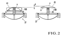
- the lens A since the central portion of the concave surface b of the lens A is chucked/fixed by the lens holder 37, the lens A can be reliably fixed. Even if, positive and negative lenses are used as lenses A, the difference in height between the convex surfaces can be reduced as compared with a case where each lens is simply placed on a glass plate. More specifically, as shown in Fig. 2, when a negative lens A1 having a power of -10D and a positive lens having a power of +6D are chucked/fixed by using the lens holder 37, a height difference d between convex surfaces a is 6.8 mm.
- this difference can be made to be smaller than the height difference (11.3 mm) between the convex surfaces of the lenses that are simply placed on a glass plate. This makes it possible to reduce the focal depth of the optical system and obtain a bright, easy-to-see projection image. In addition, if a lens is placed on the glass plate, halation occurs. However, since the narrow lens support cylinder 42 is used, the occurrence of halation can also be prevented.
- the image sensing unit 48 is placed on the convex surface side of the lens A, and the convex surface of the lens A is irradiated with light from the light source 31. An image of this convex surface is then reflected by the reflection screen 40 placed on the concave surface side of the lens A to return to the convex surface side of the lens A so as to be formed on the image sensing unit 48.
- this apparatus since this apparatus includes the multifocal lens light source 41 for irradiating the concave surface of the lens A with light, if the lens A is a multifocal lens, optical characteristics, e.g., the eyepoint position and geometrical center, can be detected by sensing an image of the segment 13B and performing image processing for the sensed image. Furthermore, since the lens A is irradiated with light from the concave surface side, and an image of the segment 13B on the surface side is guided to the image sensing unit 48, even if a lens having an astigmatic power is handled, no image distortion caused by the cylinder axis, a good image can be obtained as in the case of a progressive multifocal lens, and image processing is facilitated.
- optical characteristics e.g., the eyepoint position and geometrical center
- the reflection screen 40 for which surface treatment for producing a light scattering effect is performed is rotated by the motor 47 serving as a driving unit, the brightness of the screen surface serving as the background of an image is made uniform. This facilitates image processing.
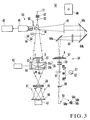
- FIG. 3 shows the arrangement of a spectacle lens image sensing processing apparatus according to the second embodiment of the present invention.
- Fig. 4 shows operation in an optical system.
- the same reference numerals as in the first embodiment denote the same parts in the second embodiment, and a description thereof will be properly omitted.
- a spectacle lens image sensing processing apparatus (to be referred to as an image sensing processing apparatus hereinafter) 52 detects the optical characteristics (the positions of a geometrical center and eyepoint) of a progressive multifocal lens 1 and multifocal lens 13 by detecting marks and measures lens powers.
- This apparatus has a mark detector 53 and power measuring device 54 which are juxtaposed, and a switching means 55 for switching the two devices.
- An image sensing unit 48 and image processing unit 49 of the mark detector 53 are commonly used for the power measuring device 54.
- the mark detector 53 is identical to the image sensing processing apparatus 30 shown in Fig. 1, and includes a progressive multifocal lens light source 31 for irradiating a lens A to be examined with light from the convex surface a side, a condenser lens 32, a stop 33, a half mirror 34, a lens holder 37 for chucking/fixing the lens A, a condenser lens 38, an imaging lens 39, a reflection screen 40, the image sensing unit 48, the image processing unit 49, a focus correction lens 50, and the like.
- the power measuring device 54 includes a lens mount base 57 on which the lens A is mounted with a concave surface b facing down, a power measuring light source 58 for irradiating the lens A with light from the concave surface b side, a light-sending lens 59 for collimating light emitted from the light source 58, a collimator lens 60 for forming a light source image on the concave surface b of the lens A, and a target 61 that is placed between the collimator lens 60 and the light-sending lens 59 to be movable in the optical axis direction.
- the power measuring device 54 also includes three mirrors 64a, 64b, and 64c arranged on the convex surface a side of the lens A, an objective lens 65, and a transmission screen 66.
- the lens A is the progressive multifocal lens 1 or multifocal lens 13 described above, its distance power is measured by the power measuring device 54.
- the lens power measurement range of the power measuring device 54 is set to, for example, -20D to +15D.
- the light source 58 is constituted by four ultra-high-luminance light-emitting diodes (LEDs) 58a to 58d, which are arranged at the respective vertices of a square centered on the optical axis to facilitate arithmetic processing.
- LEDs ultra-high-luminance light-emitting diodes
- Each of the LEDs 58a to 58d is spaced apart from the optical axis by about 2 mm.
- the peak wavelength light emitted from each of the LEDs 58a to 58d is 715.2 nm.
- a pinhole plate with a pinhole 62 formed in the center and having a diameter of about 1 mm is used as the target 61.
- An image of the pinhole 62 is formed as a pattern image of the target 61 on the transmission screen 66 owing to the effects of the collimator lens 60 and objective lens 65.
- the objective lens 65 is placed between the mirrors 64a and 64b.
- the transmission screen 66 is formed by a milky synthetic resin plate or ground glass and placed on the opposite side of the half mirror 34 of the mark detector 53 to the image sensing unit 48.
- the switching means 55 is comprised of a shutter 68 and a driving unit 69 such an air cylinder for selectively inserting the shutter 68 in the optical path between the half mirror 34 and the lens holder 37.
- a driving unit 69 such an air cylinder for selectively inserting the shutter 68 in the optical path between the half mirror 34 and the lens holder 37.
- a return-to-origin state 300 is held as shown in Fig. 4.
- the focus correction lens 50 and switching means 55 are retracted from the optical path of the mark detector 53.
- all the light sources 31, 41, and 58 are kept off.
- the same operation as that in the first embodiment is performed by the mark detector 53. More specifically, when the lens A is the progressive multifocal lens 1, the progressive multifocal lens light source 31 is turned on, and mark detection is performed while the focus correction lens 50 and switching means 55 are retracted from the optical path of the mark detector 53 (step 301 in Fig. 4). During this operation, the multifocal lens light source 41 and power measurement light source 58 are kept off.
- the lens A is the multifocal lens 13
- the multifocal lens light source 41 is turned on, and the segment is detected (step 302 in Fig. 4) while the focus correction lens 50 is inserted in the optical path and the switching means 55 is retracted from the optical path.
- the progressive multifocal lens light source 31 and power measurement light source 58 are kept off.
- the focus correction lens 50 is retracted from the optical path of the mark detector 53, and the switching means 55 is inserted in the optical path (step 303 in Fig. 4).
- the transmission screen 66 is illuminated by the light source (light source image)
- the light emitted from the light source 58 is collimated by the light-sending lens 59 and illuminates the pinhole plate 61.
- This light reaches the collimator lens 60.
- the light is then focused at the position of the concave surface b of the lens A by the collimator lens 60 to form a light source image.
- This light beam becomes divergent light again and reaches the objective lens 65 to illuminate the transmission screen 66.
- the pinhole image 62 of the pinhole plate 61 is formed on the transmission screen 66, and the lens to be examined has no power (0.00D)
- the pinhole image 62 of the target 61 is collimated by the collimator lens 60, and the pinhole image is formed on the transmission screen 66 owing to the effect of the objective lens 65. That is, when the LEDs 58a to 58d are sequentially turned on while the lens A is not placed on the lens mount base 57, the light passes through the pinhole 62 of the pinhole plate 61, collimator lens 60, mirror 64a, and objective lens 65, mirror 64b, and mirror 64c to project the pinhole image on the transmission screen 66.
- the pinhole plate 61 is held at a reference position to form a pinhole image at substantially the same position when the LEDs 58a to 58d are turned on one by one.
- the pinhole image projected on the transmission screen 66 is transmitted through the transmission screen 66 and sensed by the image sensing unit 48.
- This pinhole image is then input to the image processing unit 49 to be subjected to image processing to calculate the position of the pinhole image.
- This position is stored as a reference position. Note that when a lens to be examined is placed and the LEDs 58a to 58d are sequentially turned on one by one, a pinhole image is not formed at substantially the same position on the transmission screen 66. For this reason, the pinhole plate 61 is moved/adjusted in the optical axis direction to form a pinhole image at substantially the same position as in the case of a general lens meter.
- the lens When the lens A is to be measured, the lens is mounted on the lens mount base 57, and the LEDs 58a to 58d are sequentially turned on one by one. In this case, since light beams from the LEDs 58a to 58d are transmitted through the lens A, the positions of the pinhole images from the respective LEDs which are projected on the transmission screen 66 are displaced from the above reference position owing to a prism effect corresponding to the lens power of the lens A (optical characteristic).
- the image sensing unit 48 senses these pinhole images.
- the image processing unit 49 then performs image processing to calculate the displacement amounts of pinhole images from the respective LEDs 58a to 58d.
- the pinhole plate 61 is moved/adjusted to form the pinhole images at substantially the same position on the subtraction unit 66.
- the movement amounts of the pinhole plate 61 in this case are stored in the image processing unit 49.
- the lens power of the lens A is then calculated by converting the displacement amounts of the pinhole images and the movement amounts of the pinhole plate 61 into a power. Note that the basic optical power calculation method is the same as that disclosed in Japanese Patent Laid-Open No. 2-2164428 filed by the present applicant.
- this image sensing processing apparatus 52 has the mark detector 53 and power measuring device 54, detection of the geometrical center, eyepoint position, and the like of the lens A and measurement of a lens power can be continuously performed by conveying the lens A from the lens holder 37 to the lens mount base 57 (or in the reverse direction) using a proper lens convey mechanism.
- the image sensing unit 48 and image processing unit 49 of the mark detector 53 are commonly used for the power measuring device 54, the image sensing processing apparatus 52 can be simplified and reduced in cost.
- This embodiment has exemplified the power measuring device 54 which uses the pinhole plate as the target 61 and measures a lens power by measuring the displacement amount of each pinhole image.
- the present invention is not limited to this.
- Various conventional power measuring methods can be used.
- the power measuring method disclosed in Japanese Patent Publication No. 8-20334 described above may be used.
- the lens holder 37 is not limited to the one designed to vacuum-chuck, and may be a glass plate like the lens mount base 57 of the power measuring device 54, on which a lens to be examined is mounted.
- This embodiment includes the mark detector 53 for detecting micro engraved marks by sensing an image of the convex surface of the lens A and performing image processing, the power measuring device 54 for measuring the lens power of the lens A, and the switching means 55 which is retractably placed with respect to the mark detector 53 to switch between mark detection and power measurement.
- mark detection and power measurement can be continuously performed.
- the image sensing unit 48 and image processing unit 49 of the mark detector 53 are commonly used for the power measuring device 54, the apparatus can be simplified and reduced in cost.
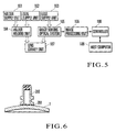
- Fig. 5 shows the arrangement of a progressive multifocal lens image sensing processing apparatus according to the third embodiment of the present invention.
- the progressive multifocal lens image sensing processing apparatus forms a layout blocker, and is juxtaposed with an edger (not shown). This apparatus image-senses a progressive multifocal lens 1 and determines, on the basis of the sensed image, whether the lens is a left- or right-eye lens.
- the apparatus performs layout processing to calculate the mounting position and angle of a processing jig (lens holder) mounted on the progressive multifocal lens 1 and blocking to mount the lens holder at the processing center of the progressive multifocal lens 1, and conveys the progressive multifocal lens 1 to the edger after the lens holder is mounted on the lens.
- layout processing to calculate the mounting position and angle of a processing jig (lens holder) mounted on the progressive multifocal lens 1 and blocking to mount the lens holder at the processing center of the progressive multifocal lens 1, and conveys the progressive multifocal lens 1 to the edger after the lens holder is mounted on the lens.
- This image sensing processing apparatus includes a holder supply unit 101 for supplying a lens holder, a seal supply unit 102 for supplying an elastic seal (to be described later), a lens supply unit 103 for supplying the progressive multifocal lens 1 to be processed, a holder holding unit 104 for mounting the lens holder, supplied by the holder supply unit 101, at the processing center of the progressive multifocal lens 1, an image sensing optical system 105 for image-sensing the progressive multifocal lens 1, an image processing unit 106 for determining, on the basis of the image sensed by the image sensing optical system 105, whether the progressive multifocal lens 1 is a left- or right-eye lens, and calculating the mounting position and angle of the lens holder, a lens convey unit 107 for conveying the progressive multifocal lens 1 to the edger after the lens holder is mounted on the lens, a controller 108 for controlling the overall image sensing processing apparatus, and a host computer 109 serving as a computation means for controlling the image sensing processing
- Fig. 6 shows a state in which the lens holder is mounted on the progressive multifocal lens 1 through an elastic seal on the basis of the image processing result obtained by the image processing unit 106.
- a lens holder 200 made of a metal such as stainless steel is molded into a collared cylindrical member.
- the surface of the lens holder 200 to which an elastic seal 201 is bonded (the lower surface of the lens holder 200) serves as a concave lens holding surface conforming to the convex lens surface of the progressive multifocal lens 1.
- the number of types of lens holders 200 increases. In this case, therefore, the radius of curvature of a lens holding surface is changed stepwise to decrease the number of types of lens holders 200, thus allowing one type of lens holder 200 to hold several types of progressive multifocal lenses 1 having different convex surface curves.
- the elastic seal 201 is formed into a ring-like shape having an outer diameter (about 22 mm) larger than the outer diameter of the lens holding surface of the lens holder 200 and an inner diameter (about 8 mm) smaller than the hole diameter of the lens holder 200 by using a rubber material as thin as about 0.5 to 06 mm.
- the two surfaces of this seal are coated with an adhesive.
- Fig. 7 shows the arrangement of the image sensing optical system 105.
- the same reference numerals as in Fig. 1 denote the same parts in Fig. 7.
- the image sensing optical system 105 is equivalent to the image sensing processing apparatus 30 in Fig. 1 from which the image processing unit 49 is omitted, and hence may use the arrangement of the image sensing processing apparatus 30.
- Fig. 7 shows the arrangement specifically designed for a progressive multifocal lens.
- the image sensing optical system 105 includes a light source 31, condenser lens 32, stop 33, half mirror 34, lens holder 37, convex lenses 38a and 38b serving as condenser lenses, imaging lens 39, reflection screen 40, motor 47, and image sensing unit 48 such as a CCD camera.
- Figs. 8 to 10 show the operation of the image sensing processing apparatus in Fig. 5.
- the operation of the image sensing processing apparatus will be described below with reference to Figs. 8 to 10.
- the lens supply unit 103 places one progressive multifocal lens 1 to be edged (to be referred to as a processing target lens 1 hereinafter) on the lens holder 37 of the image sensing optical system 105 with the convex surface of the lens facing up.
- the lens holder 37 chucks/fixes the processing target lens 1 on the opening portion of the upper surface of a lens support cylinder 42 by evacuating the interior of the lens support cylinder 42 (step S1 in Fig. 8).
- the holder supply unit 101 supplies the lens holders 200 one by one to the holder holding unit 104 under the control of the controller 108.
- the elastic seal 201 is loaded in the form of a roll in the seal supply unit 102.
- the surface of this roll is covered with a protective sheet.
- the seal supply unit 102 supplies the elastic seals 201 one by one to the holder holding unit 104 with the protective sheets peeling off.
- the holder holding unit 104 Upon reception of the lens holder 200 and elastic seal 201, the holder holding unit 104 holds the lens holder 200 and bonds the elastic seal 201 to the lens holding surface of the lens holder 200. The holder holding unit 104 is then set in a standby state to prepare for mounting of the lens holder 200 on the processing target lens 1 (step S2).
- the controller 108 then turns on the light source 31 of the image sensing optical system 105 (step S3). Subsequently, the image processing unit 106 resets a time-up timer for image processing to 0 and starts it in accordance with an instruction from the controller 108, thus starting time measurement (step S4). This time-up timer is used to measure the elapsed time in image processing for one processing target lens 1.
- Illumination light from the light source 31 passes through the condenser lens 32, stop 33, and half mirror 34 and strikes the processing target lens 1.
- an image of micro engraved marks 3A and 3B, numeral 4, and identification mark 5 formed on the surface of the processing target lens 1 is focused by the convex lenses 38a and 38b and projected on the reflection screen 40 through the imaging lens 39.
- the image projected on the reflection screen 40 passes through the imaging lens 39 and convex lenses 38b and 38a and is reflected by the half mirror 34 to be projected on the light-receiving surface of the image sensing unit 48.
- the image sensing unit 48 photoelectrically converts the image projected on the light-receiving surface into an image signal and outputs it.
- the image processing unit 106 A/D-converts the image signal output from the image sensing unit 48 of the image sensing optical system 105 and temporarily stores the image data obtained by A/D conversion in the internal memory (step S5).
- the image processing unit 106 starts image processing for the input image stored in the memory.
- Figs. 11A to 12B show how image processing is performed by the image processing unit 106.
- the image processing unit 106 compares the input image shown in Fig. 11A with a predetermined first threshold, and extracts pixels whose luminance values are equal to or more than the first threshold from the image without any change.
- the image processing unit 106 performs static threshold processing for pixels whose luminance values are less than the first threshold to set the luminance values to 0, thereby removing the background area from the input image and extracting a lens area.
- the image processing unit 106 stores this lens area in the memory (step S6).
- the image processing unit 106 calculates the difference between the blurred image obtained by smoothing the image stored in the memory, which has undergone the static threshold processing, and the image having undergone the static threshold processing for each pixel, and performs dynamic threshold processing to assign "1" to each pixel corresponding to the calculated difference equal to or more than a predetermined second threshold and assign "0" to each pixel corresponding to the calculated difference less than the second threshold, thereby binarizing the image having undergone the static threshold processing (step S7).
- the contours are sharpened by difference processing, and "1" is assigned to each portion exhibiting a large difference output, i.e., each portion that is likely to be a contour portion of an object, while "0" is assigned to each of the remaining portions. Even if, therefore, slight illumination irregularity or halation occurs in image-sensing the processing target lens 1, the shapes of the micro engraved marks 3A and 3B, numeral 4, and identification mark 5 can be extracted. With this dynamic threshold processing, an image like the one shown in Fig. 11B can be obtained.
- the image processing unit 106 stores the image having undergone the dynamic threshold processing in the memory.
- the binarized image contains dust, dirt, and the like on the surface of the processing target lens 1, and the binarized micro engraved marks are often partly omitted. For this reason, the micro engraved marks 3A and 3B cannot be directly detected from the binarized image obtained by dynamic threshold processing. Therefore, the micro engraved marks 3A and 3B are detected by, for example, removing noise components or repairing the omitted portions of the micro engraved marks 3A and 3B.
- the image processing unit 106 performs labeling processing in which a set of concatenated pixels "1" in the binarized image having undergone dynamic threshold processing is regarded as one concatenation component, and the same label (number or name) is assigned to each pixel within the same concatenation component.
- the image processing unit 106 then extracts geometrical feature parameters from the respective concatenation components and stores them in the memory. In this case, as feature parameters of each concatenation component, the image processing unit 106 extracts an area S of the concatenation component (the number of pixels of the concatenation component) shown in Fig. 11C and the ratio (L1/L2) of a major axis L1 to a minor axis L2.
- Each of Figs. 11C to 11I shows a pixel-"1" region by hatching.
- the image processing unit 106 extracts a concatenation component whose area S falls within a predetermined first area range and ratio of the major axis L1 to the minor axis L2 is equal to or less than a predetermined ratio threshold (e.g., 1.2) as a circular micro engraved mark candidate region (to be referred to as a ⁇ similar region hereinafter), and stores the position of this extracted ⁇ similar region in the memory (step S8). In this manner, for example, a ⁇ similar region like the one shown in Fig. 11D can be extracted.
- a predetermined ratio threshold e.g., 1.2
- This ⁇ similar region contains projection-like noise components.
- the image processing unit 106 compresses the extracted ⁇ similar region by a predetermined number of pixels first, and then decompresses the region by the same number of pixels.
- the projection-like noise components disappear. If, therefore, the compressed ⁇ similar region is decompressed, the projection-like noise components can be removed from the ⁇ similar region (step S9).
- the reflecting surface also contains noise components such as holes and omissions.
- the image processing unit 106 expands the ⁇ similar region, from which projection-like noise components have been removed, by a predetermined number of pixels to remove noise components such as holes and omissions from the ⁇ similar region, thus performing shape correction (step S10).
- shape correction step S10
- a ⁇ similar region having undergone shape correction like the one shown in Fig. 11E can be obtained.
- the image processing unit 106 then fills the inside of each ⁇ similar region having undergone shape correction with pixels "1" as shown in Fig. 11F, extracts geometrical feature parameters of each ⁇ similar region, and stores them in the memory. In this case as well, as the feature parameters, the area S of each ⁇ similar region and the ratio of the major axis L1 to the minor axis L2 are extracted.
- the image processing unit 106 extracts a ⁇ similar region whose area S falls within a predetermined second area range and ratio of the major axis L2 to the minor axis L2 is equal to or less than the above ratio threshold as a most promising candidate area (to be referred to as a ⁇ region hereinafter) for a circular micro engraved mark, and stores the extracted ⁇ region in the memory (step S11).
- the image processing unit 106 counts the number of extracted ⁇ regions and stores the count in the memory (step S12).
- the image processing unit 106 performs labeling processing for the binarized image having undergone the dynamic threshold processing, extracts geometrical feature parameters of each concatenation component, and stores them in the memory.
- feature parameters of each concatenation component the area S, major axis L1, and minor axis L2 of each concatenation component are extracted.
- the image processing unit 106 extracts a rodlike concatenation component whose area S falls within a predetermined third area range, major axis L1 falls within a predetermined major axis range, and minor axis L2 falls within a predetermined minor axis range as a region that is likely to be a constituent element of an H-shaped micro engraved mark, and stores the position of the rodlike concatenation component extracted in this manner in the memory (step S13). In this manner, for example, regions like those shown in Fig. 11G can be extracted.
- the three rodlike regions shown in Fig. 11G constitute a shape similar the letter "H", but are not concatenated with each other.
- the image processing unit 106 therefore expands the extracted rodlike regions by a predetermined number of pixels (e.g., about two pixels) to concatenate these regions, thereby obtaining a candidate region for an H-shaped micro engraved mark (to be referred to as an H similar region hereinafter) (step S14). With this operation, an H similar region having undergone shape correction like the one shown in Fig. 11H can be obtained.
- the image processing unit 106 compresses the H similar region having undergone shape correction by a predetermined number of pixels first, and then decompresses it by the same number of pixels, thereby removing projection-like noise components from the H similar region (step S15).
- the image processing unit 106 extracts geometrical feature parameters from the H similar region from which noise components have been removed, and stores them in the memory. In this case, as the feature parameters of the H similar region, the image processing unit 106 extracts the ratio (HT/W) of a height HT to a width W of the H similar region shown in Fig.
- the convexity (the degree indicating how the graphic pattern is dented on a two-dimensional plane), a diameter D of a circle circumscribing the H similar region, and the distance from the above ⁇ region.
- the convexity becomes less than 1 if there are recesses and holes in the circle.
- the image processing unit 106 extracts an H similar region whose ratio of the height HT to the width W falls within a predetermined ratio range, convexity falls within a predetermined range (e.g., 0.6 to 0.7), diameter D of the circumscribed circle falls within a predetermined diameter range, and distance from the ⁇ region falls within a predetermined distance range as a most promising candidate region (to be referred to as an H region hereinafter) for an H-shaped micro engraved mark, and stores the position of the extracted H region in the memory (step S16). The image processing unit 106 then counts the number of H regions extracted and stores the count in the memory (step S17).
- a predetermined range e.g., 0.6 to 0.7
- diameter D of the circumscribed circle falls within a predetermined diameter range
- distance from the ⁇ region falls within a predetermined distance range as a most promising candidate region (to be referred to as an H region hereinafter) for an H-shaped micro engraved mark
- the image processing unit 106 checks whether the number of ⁇ regions counted in step S12 is 2 (step S18). If the number of ⁇ regions is not 2, the image processing unit 106 checks whether the number of ⁇ regions is 1 (step S19). If the number of ⁇ regions is 1, the image processing unit 106 checks whether the number of H regions counted in step S17 is 1 (step S20). If the number of ⁇ region is neither 2 nor 1, the image processing unit 106 checks whether the elapsed time measured by the time-up timer exceeds a predetermined sec (e.g., 4 sec) (step S21).
- a predetermined sec e.g., 4 sec
- the image processing unit 106 executes the processing in steps S5 to S20 again. In this manner, if the number of ⁇ regions is neither 2 nor 1 or the number of ⁇ regions is 1 and the number of H regions is not 1 (i.e., a portion other than the micro engraved marks 3A and 3B is detected), and the elapsed time does not exceed the predetermined seconds, the image processing unit 106 executes the processing in steps S5 to S20 again.
- step S21 it is determined in step S21 that the elapsed time exceeds the predetermined seconds, the image processing unit 106 determines that the micro engraved marks 3A and 3B cannot be detected by image processing, and performs image processing impossibility error processing to notify the controller 108 of the impossibility of image processing. Upon reception of the notification, the controller 108 performs processing, e.g., removing the processing target lens 1 suffering the image processing impossibility error from the image sensing processing apparatus.
- the image processing unit 106 obtains the distance between the two ⁇ regions or the distance between the ⁇ region and H region, and checks whether the distance falls within a predetermined range centered on a predetermined value (e.g., 34 mm) (step S22). If the obtained distance falls outside the predetermined range centered on the predetermined value, the flow advances to step S21.
- a predetermined value e.g. 34 mm
- the image processing unit 106 sets the center of the minimum circumscribed circle of the ⁇ region as the center of the ⁇ region and the center of the minimum circumscribed circle of the H region as the center of the H region, calculates the coordinates of the centers of the ⁇ region and H region, and stores them in the memory (step S24).
- the image processing unit 106 calculates the coordinates of a middle point (reference position) C between the center of the ⁇ region and the center of the H region as shown in Fig. 12A, and stores it in the memory (step S25).
- the image processing unit 106 further obtains a line segment connecting the center of the ⁇ region and the center of the H region (a vector extending from the ⁇ region to the H region) V, calculates an angle defined by the vector V and a horizontal reference line 2 of the image sensing processing apparatus (the rotational angle of the processing target lens 1 with respect to the horizontal reference line 2) ⁇ , and stores it in the memory (step S26).
- an angular deviation is caused with respect to a right position on the apparatus.
- the processing in step S26 is performed to obtain this angular deviation.
- the image processing unit 106 extracts two rectangular regions ⁇ 1 and ⁇ 2, each having a predetermined size, from the binarized image having undergone the above dynamic threshold processing, which are located on either of the left and right sides (the left side in this embodiment) when the ⁇ region is viewed from the H region, and are respectively spaced apart from the centers of the ⁇ region and H region by a predetermined distance in a direction perpendicular to the vector V (step S27).
- the image processing unit 106 rotates the rectangular regions ⁇ 1 and ⁇ 2 through the rotational angle ⁇ to make them parallel to the horizontal reference line 2 (step S28).
- the rectangular regions ⁇ 1 and ⁇ 2 are rotated to facilitate extraction of characters in the next character counting processing.
- the image processing unit 106 counts the number of characters in the rectangular regions ⁇ 1 and ⁇ 2 by extracting characters in the rectangular regions ⁇ 1 and ⁇ 2 after the rotation processing one by one, and stores the count in the memory (step S29).
- the size and pitch of characters formed as the numeral 4 and identification mark 5 on the processing target lens 1 are known.
- the image processing unit 106 therefore compresses the images in the rectangular regions ⁇ 1 and ⁇ 2 in only the horizontal direction to remove noise components such as short circuits between the characters, and extracts the characters by using a pre-processing technique used in a character recognition technique. More specifically, the image processing unit 106 detects the spaces between periodic characters on the basis of the character pitch, and detects character regions on the basis of the character size, thereby determining character extraction positions.
- the image processing unit 106 checks whether the processing target lens 1 is a right- or left-eye lens (step S30). On the progressive multifocal lens 1 on which the circular micro engraved mark 3A and H-shaped micro engraved mark 3B are formed in advance, the micro engraved mark 3A and numeral 4 representing the addition power are present on the ear side, and the micro engraved mark 3B and identification mark 5 representing the type of lens are present on the nose side. If, therefore, the numeral 4 and identification mark 5 are present on the right side when the H region is viewed from the ⁇ region, the lens 1 is a right-eye lens (Fi. 12B). If the numeral 4 and identification mark 5 are present on the left side, the lens 1 is a left-eye lens (Fig. 12A).
- the rectangular regions ⁇ 1 and ⁇ 2 located on the left side when the H region is viewed from the ⁇ region are extracted by the processing in step S27. If the number of characters counted in step S29 falls within a predetermined range (e.g., 3 (inclusive) to 7 (inclusive)), the image processing unit 106 determines that the lens is a left-eye lens. If the number of characters falls outside the predetermined range, the image processing unit 106 determines that the lens is a right-eye lens. If the lens is a right-eye lens, the number of characters in the rectangular regions ⁇ 1 and ⁇ 2 should be 0. If the lens is a left-eye lens, the number of characters should be 5. However, in consideration of character recognition errors, the image processing unit 106 determines that the lens is a left-eye lens, if the number of characters falls within a predetermined range.
- a predetermined range e.g., 3 (inclusive) to 7 (inclusive)
- the image processing unit 106 checks whether the numeral 4 and identification mark 5 are located below the micro engraved marks 3A and 3B (step S31). Assume that it is determined in step S30 that the lens is a right-eye lens. In this case, if the vector V is a rightward vector, the numeral 4 and identification mark 5 are located below the micro engraved marks 3A and 3B, whereas if the vector V is a leftward vector, they are located above the micro engraved marks 3A and 3B. Assume that it is determined that the lens is a left-eye lens.
- the numeral 4 and identification mark 5 are located below the micro engraved marks 3A and 3B, whereas if the vector V is a rightward vector, they are located above the micro engraved marks 3A and 3B.
- the image processing unit 106 performs upside down error processing to notify the controller 108 that the processing target lens 1 is upside down and falls outside the allowable range of the image sensing processing apparatus.
- the controller 108 performs processing, e.g., removing the processing target lens 1 suffering the upside down error from the image sensing processing apparatus.
- the image processing unit 106 checks whether the rotational angle ⁇ falls within a predetermined range (e.g., ⁇ 60°) (step S32). If the rotational angle ⁇ falls outside the predetermined range, the image processing unit 106 performs angle over error processing to notify the controller 108 that the rotational angle of the processing target lens 1 falls outside the allowable range of the image sensing processing apparatus. Upon reception of the notification, the controller 108 performs processing, e.g., removing the processing target lens 1 suffering the angle over error from the image sensing processing apparatus.
- a predetermined range e.g., ⁇ 60°
- step S44 the flow advances to step S44 in Fig. 10.
- step S22 If the distance obtained in step S22 falls within a predetermined range centered on a predetermined value, and the number of ⁇ regions is 2 (NO in step S23 in Fig. ), the image processing unit 106 sets the centers of the minimum circumscribed circles of the respective regions as the centers of the respective ⁇ regions, calculates the coordinates of the centers of the two ⁇ regions, and stores them in the memory (step S33).
- the image processing unit 106 then calculates the coordinates of the middle point C (geometrical center O) between the centers of the two ⁇ regions as shown in Fig. 12B and stores them in the memory (step S34).
- the image processing unit 106 also obtains the line segment V connecting the centers of the two ⁇ regions, calculates the angle (rotational angle) ⁇ defined by this line segment V and the horizontal reference line 2, and stores it in the memory (step S35).
- the image processing unit 106 extracts four rectangular regions ⁇ 1 to ⁇ 4, each having a predetermined size, from the binarized image having undergone the above dynamic threshold processing, which are spaced apart from the centers of the respective ⁇ regions by a predetermined distance in a direction perpendicular to the line segment V (step S36). The image processing unit 106 then rotates one of the extracted rectangular regions through the rotational angle ⁇ to make it parallel to the horizontal reference line 2 (step S37).
- the image processing unit 106 counts the number of characters in the rectangular region having undergone the rotation processing in the same manner as in step S29, and stores the count in the memory (step S38).
- the image processing unit 106 checks whether the number of characters counted in step S38 is 3 (step S39). If the number of characters is not 3, the image processing unit 106 selects another region from the four rectangular regions ⁇ 1 to ⁇ 4 (steps S40 and S41), and performs the processing in steps S36 to S39.
- the image processing unit 106 determines that it is impossible to determine whether the lens is a left- or right-eye lens, and performs left-/right-eye lens determination impossibility processing to determine on the basis of information notified in advance from the host computer 109 whether the processing target lens 1 is a right- or left-eye lens. The flow then advances to step S32.
- the image processing unit 106 determines that the processing target lens 1 is a right- or left-eye lens (step S42).
- the processing target lens 1 is a right- or left-eye lens (step S42).
- the 3-digit numeral 4 representing the addition power is present on the ear side
- an the identification mark 5 representing the type of lens is present on the nose side. If, therefore, the rectangular region in which the number of characters is 3 is one of the rectangular regions ⁇ 1 and ⁇ 3 shown in Fig. 12B, the lens is a right-eye lens. If this region is one of the rectangular regions ⁇ 2 and ⁇ 4, the lens is a left-eye lens.
- the image processing unit 106 then checks whether the numeral 4 and identification mark 5 are located below the micro engraved marks 3A and 3C (step S43). If the rectangular region in which the number of characters is 3 is one of the rectangular regions ⁇ 3 and ⁇ 4, the numeral 4 and identification mark 5 are located below the micro engraved marks 3A and 3C. If this region is one of the rectangular regions ⁇ 1 and ⁇ 2, the numeral 4 and identification mark 5 are located above the micro engraved marks 3A and 3C.
- the image processing unit 106 performs upside down error processing as described above.
- the image processing unit 106 performs the processing in step S32 described above.
- step S44 the image processing unit 106 sends the left-/right-eye lens determination result on the processing target lens 1, the calculated coordinates of the middle point C, and the calculated rotational angle ⁇ to the controller 108.
- the controller 108 transmits the left-/right-eye lens determination result on the processing target lens 1 and rotational angle ⁇ to the host computer 109.
- the controller 108 also turns on the light source 31 of the image sensing optical system 105 (step S45).
- the host computer 109 has already recognized the processing target lens 1 as a right- or left-eye lens by reading a bar code stuck on the tray of the processing target lens 1 using a bar code reader when the lens was supplied to the image sensing processing apparatus.
- the host computer 109 can check whether the contents represented by the bar code coincide with the actual processing target lens 1 placed on the tray, by collating the result read from the bar code with the left-/right-eye lens determination result sent from the controller 108.
- the host computer 109 performs angle correction with respect to the prestored layout data of the processing target lens 1 (the data representing the positional relationship between the geometrical center O, micro engraved marks 3A and 3B, and eyepoint 11) in accordance with the rotational angle ⁇ , and then computes block data (data representing the position of the eyepoint 11 with reference to the geometrical center O) on the basis of the layout data having undergone the angle correction.
- the host computer 109 transmits the block data to the controller 108 (step S46).
- the middle point C detected by the image processing unit 106 is the geometrical center O of the processing target lens 1.
- This middle point C deviates from the normal position on the image sensing processing apparatus due to the positional deviations caused in the horizontal direction (the lateral direction in Figs. 12A and 12B) and vertical direction (the longitudinal direction in Figs. 12A and 12B) when the lens was supplied. That is, the processing target lens 1 has undergone positional deviations in the horizontal and vertical directions.
- the block data has been calculated on the premise that the angular deviation of the processing target lens 1 has been corrected as described, and there are no positional deviations in the horizontal and vertical directions.
- the controller 108 corrects the positional deviations of the processing target lens 1 in the horizontal and vertical directions on the basis of the coordinates of the middle point C, and then controls the lens supply unit 103 to position the eyepoint 11 of the processing target lens 1 immediately below the lens holder 200 held by the holder holding unit 104 on the basis of block data from the host computer 109 (step S47).
- the controller 108 controls the holder holding unit 104 to rotate the lens holder 200 through the rotational angle ⁇ to perform angle correction (step S48).
- the controller 108 then controls the holder holding unit 104 to lower the lens holder 200 so as to bring the elastic seal 201 stuck on the lens holder 200 into tight contact with the processing target lens 1.
- the lens holder 200 is mounted at the processing center (eyepoint 11) of the processing target lens 1 through the elastic seal 201 (step S49).
- the controller 108 controls the holder holding unit 104 to convey the lens holder 200 to a predetermined extraction position, together with the processing target lens 1 (step S50), and then controls the lens convey unit 107 to convey the processing target lens 1 at the extraction position to the edger (step S51).
- the processing target lens 1 conveyed to the edger is subjected to edging such as an arris process by the edger on the basis of the lens frame shape data and the prescription data of a wearer, thereby manufacturing a spectacle lens having a contour shape almost conforming to the shape of a frame.
- an image of the processing target lens 1 is sensed and binarized. Geometrical feature parameters of each graphic pattern contained in the binarized image are extracted. Graphic patterns with these feature parameters satisfying predetermined conditions are extracted as images of the micro engraved marks 3A, 3B, and 3C formed on the processing target lens 1 in advance.
- the reference position (geometrical center) C or O having a predetermined positional relationship with the processing center position 11 is obtained on the binarized image on the basis of the positions of the extracted micro engraved marks.
- the reference position of the processing target lens 1 can be obtained by detecting the micro engraved marks 3A, 3B, and 3C by image processing.
- the relationship between the reference position O and the processing center position 11 changes depending on the spectacle lens to be processed.
- the time required to detect the micro engraved marks 3A, 3B, and 3C can be shortened as compared with the conventional method using template matching.
- the cost can be reduced.
- the spectacle lens 1 and lens holder 200 can be positioned with higher precision than in the case where they are positioned manually by an operator. The burden imposed on the operator can greatly be reduced. As a consequence, the spectacle lens 1 and lens holder 200 can be accurately and efficiently positioned in a short period of time.
- the processing center position 11 of the spectacle lens 1 can be obtained upon angle correction.
- processing for the spectacle lens 1 suffering a considerable angular deviation can be stopped.
- the numeral 4 representing the addition power which is formed on the spectacle lens 1 in advance is detected on the binarized image on the basis of the positions of the micro engraved marks 3A, 3B, and 3C to check on the basis of the position of the detected numeral whether the spectacle lens 1 is a right- or left-eye lens. This makes it possible to check whether the spectacle lens 1 different from a desired lens is supplied by mistake. If it is determined that the spectacle lens 1 is supplied by mistake, the processing for the spectacle lens 1 can be stopped.
- the numeral 4 representing the addition power which is formed on the spectacle lens 1 in advance is detected on the binarized image on the basis of the positions of the micro engraved marks 3A, 3B, and 3C to determine the vertical posture of the spectacle lens 1 on the basis of the position of the detected numeral 4. This makes it possible to stop the processing for the spectacle lens 1 supplied upside down.
- Layout data representing the positional relationship between the reference position O and the processing center position 11 is stored in the host computer 109 serving as a computation means independent of the image processing unit 106.
- the host computer 109 is then made to calculate the processing center position 11 of the spectacle lens 1. This eliminates the necessity to hold a large volume of data in the image processing unit 106, and facilitates registration of layout data corresponding to the spectacle lens 1 to be processed.
- a multifocal lens image sensing processing apparatus will be described next.
- a multifocal lens layout blocker When a multifocal lens layout blocker is to be implemented, the arrangement of an image sensing processing apparatus remains the same as that shown in Fig. 5. Hence, this apparatus will be described by using the same reference numerals as in Fig. 5.
- Fig. 13 shows the arrangement of an image sensing optical system 105 for multifocal lenses.
- the same reference numerals as in Fig. 1 denote the same parts in Fig. 13.
- the image sensing optical system 105 is equivalent to the image sensing processing apparatus 30 shown in Fig. 1 from which the image processing unit 49 is omitted, and hence may use the arrangement of the image sensing processing apparatus 30.
- Fig. 13 shows the arrangement specifically designed for a multifocal lens.
- the image sensing optical system 105 includes a half mirror 34, lens holder 37, convex lenses 38b and 38a, imaging lens 39, reflection screen 40, light source 41, motor 47, image sensing unit 48, and focus correction lens 50.
- Figs. 14 and 15 show the operation of the image sensing processing apparatus according to this embodiment. The operation of the image sensing processing apparatus will be described in detail below with reference to Figs. 14 and 15.
- a lens supply unit 103 places one multifocal lens 13 to be edged (to be referred to as a processing target lens 13 hereinafter) on a lens support cylinder 42 of the image sensing optical system 105 with the convex surface of the lens facing up under the control of a controller 108.
- the lens support cylinder 42 chucks/fixes the processing target lens 13 on the opening portion of the upper surface of the lens support cylinder 42 by evacuating the interior of the lens support cylinder 42 (step S61 in Fig. 14).
- a holder supply unit 101 supplies lens holders 200 one by one to a holder holding unit 104 under the control of the controller 108.
- Each elastic seal 201 is loaded in the form of a roll in a seal supply unit 102.
- the surface of this roll is covered with a protective sheet.
- the seal supply unit 102 supplies the elastic seals 201 one by one to the holder holding unit 104 with the protective sheets peeling off.
- the holder holding unit 104 Upon reception of the lens holder 200 and elastic seal 201, the holder holding unit 104 holds the lens holder 200 and bonds the elastic seal 201 to the lens holding surface of the lens holder 200. The holder holding unit 104 is then set in a standby state to prepare for mounting of the lens holder 200 on the processing target lens 13 (step S62).
- the controller 108 then turns on the light source 41 of the image sensing optical system 105 (step S63). Subsequently, an image processing unit 106 resets a time-up timer for image processing to 0 and starts it in accordance with an instruction from the controller 108, thus starting time measurement (step S64). This time-up timer is used to measure the elapsed time in image processing for one processing target lens 1.
- Illumination light from the light source 41 is reflected by the reflection screen 40. This light passes through the imaging lens 39 and condenser lenses 38b and 38a and strikes the concave surface of the processing target lens 13.
- the image transmitted through the processing target lens 13 is reflected by the half mirror 34, passes through the focus correction lens 50, and is projected on the light-receiving surface of the image sensing unit 48.
- the image sensing unit 48 photoelectrically converts the image projected on the light-receiving surface and outputs the resultant image signal.
- the focus correction lens 50 is a lens for focusing the image sensing unit 48 on the convex surface of the processing target lens 13.
- the processing target lens 13 used in this embodiment is a multifocal lens called a one-piece type lens made of plastic.
- a multifocal lens called a one-piece type lens is designed such that a segment 13B protrudes in the form of a wedge on the convex surface side of the lens, and there is a level difference at the boundary between a main lens 13A and the segment 13B, as shown in Fig. 19.
- the processing target lens 13 is irradiated with illumination light from one surface side (the concave surface side in this embodiment), and the image sensing unit 48 is placed on the other surface side (convex surface side) to project only an image of the upper rim 17 of the segment 13B on the light-receiving surface of the image sensing unit 48.
- the image sensing unit 48 is placed on the other surface side (convex surface side) to project only an image of the upper rim 17 of the segment 13B on the light-receiving surface of the image sensing unit 48.
- the image processing unit 106 includes a memory for storing image data and an arithmetic processing section for performing various arithmetic processes for the image data in accordance with a program.
- the image processing unit 106 A/D-converts the image signal output from the image sensing unit 48 of the image sensing optical system 105, and temporarily stores the resultant image data in the internal memory (step S65).
- Figs. 16A to 16F show how image processing is performed by the image processing unit 106.
- the image processing unit 106 compares the input image shown in Fig. 16A with a predetermined first threshold, and extracts pixels whose luminance values are equal to or more than the first threshold from the image without any change.
- the image processing unit 106 performs static threshold processing for pixels whose luminance values are less than the first threshold to set the luminance values to 0, thereby removing the background area from the input image and extracting a lens area.
- the image processing unit 106 stores this lens area in the memory (step S66).
- the image processing unit 106 calculates the difference between the blurred image obtained by smoothing the image stored in the memory, which has undergone the static threshold processing, and the image having undergone the static threshold processing for each pixel, and performs dynamic threshold processing to assign "1" to each pixel corresponding to the calculated difference equal to or more than a predetermined second threshold and assign "0" to each pixel corresponding to the calculated difference less than the second threshold, thereby binarizing the image having undergone the static threshold processing (step S67).
- the contours are sharpened by difference processing, and "1" is assigned to each portion exhibiting a large difference output, i.e., each portion that is likely to be a contour portion of an object, while "0" is assigned to each of the remaining portions. Even if, therefore, slight illumination irregularity or halation occurs in image-sensing the processing target lens 13, the shape of the upper rim (to be referred to as a segment top hereinafter) 17 of the segment 13B can be extracted. With this dynamic threshold processing, an image like the one shown in Fig. 16B can be obtained.
- the image processing unit 106 stores the image having undergone the dynamic threshold processing in the memory.
- the binarized image often contains dust, dirt, and the like on the surface of the processing target lens 13. For this reason, the segment top cannot be directly detected from the binarized image obtained by dynamic threshold processing. Therefore, the segment top is detected by removing noise components.
- the image processing unit 106 performs labeling processing in which a set of concatenated pixels "1" in the binarized image having undergone dynamic threshold processing is regarded as one concatenation component, and the same label (number or name) is assigned to each pixel within the same concatenation component.
- the image processing unit 106 then extracts geometrical feature parameters from the respective concatenation components and stores them in the memory. In this case, as feature parameters of each concatenation component, the image processing unit 106 extracts an area S, major axis L1, and minor axis L2 of the concatenation component (the number of pixels of the concatenation component) shown in Fig. 16C.
- Each of Figs. 16C to 16F shows a pixel-"1" region by hatching.
- the image processing unit 106 extracts a concatenation component whose area S falls within a first area range, major axis L1 falls within a predetermined major axis range, and minor axis L2 falls within a predetermined minor axis range as a region similar to the segment top (to be referred to as a segment top region ST hereinafter), and stores the position of the extracted segment top region ST in the memory (step S68). In this manner, the segment top region ST like the one shown in Fig. 16D can be extracted.
- the extracted segment top region ST contains projection-like noise components. For this reason, the image processing unit 106 compresses the extracted segment top region ST by a predetermined number of pixels first, and then decompresses the region by the same number of pixels. When the segment top region ST is compressed, the projection-like noise components disappear. If, therefore, the segment top region ST is decompressed, the projection-like noise components can be removed from the segment top region ST and shape correction can be performed (step S69).
- the image processing unit 106 obtains a smallest rectangle R containing the segment top region ST, as shown in Fig. 16E (step S70).
- the image processing unit 106 counts the number of segment top regions ST and stores the count in the memory (step S71).
- the image processing unit 106 checks whether the number of segment top regions counted in step S71 is 1 (step S72). If the number of segment top regions is not 1, the image processing unit 106 checks whether the elapsed time that is being measured by the time-up timer exceeds predetermined seconds (e.g., 4 sec) (step S73).
- predetermined seconds e.g. 4 sec
- the image processing unit 106 executes the processing in steps S65 to S72 again. In this manner, if the number of segment top regions is not 1 (i.e., a portion other than the segment top is detected) and the elapsed time does not exceed the predetermined seconds, the processing in steps S65 to S72 is repeatedly executed.
- step S73 If it is determined in step S73 that the elapsed time exceeds the predetermined seconds, the image processing unit 106 determines that the segment top cannot be detected by image processing, and performs image processing impossibility error processing to notify the controller 108 of the impossibility of image processing. Upon reception of the notification, the controller 108 performs processing, e.g., removing the processing target lens 13 suffering the image processing impossibility error from the image sensing processing apparatus.
- step S72 If it is determined in step S72 that the number of segment top regions is 1, the image processing unit 106 calculates the coordinates of a center C of the rectangle R and the coordinates of a contact point P (reference position) of the segment top region ST and a long side of the rectangle R, and also obtains a longitudinal axis AL of the rectangle R, as shown in Fig. 16F.
- the image processing unit 106 then calculates an angle (the rotational angle of the processing target lens 13 with respect to a horizontal reference line 2) ⁇ defined by the axis AL and the horizontal reference line 2 of the image sensing processing apparatus, and stores the coordinates of the center C and contact point P and the rotational angle ⁇ in the memory (step S74).
- the processing target lens 13 has undergone an angular deviation, when supplied, with respect to the normal position on the image sensing processing apparatus. To calculate the rotational angle ⁇ is to obtain this angular deviation.
- the image processing unit 106 calculates the coordinates of a center of gravity D of the segment top region ST and stores it in the memory (step S75).
- step S76 the image processing unit 106 checks whether the coordinates of the center C, contact point P, and center of gravity D and the rotational angle ⁇ are acquired five times (step S76). If they are not acquired five times, the flow returns to step S64 to reset the time-up timer to 0 and perform the above processing again. With this operation, the processing in steps S64 to S75 is repeated until the respective coordinates and rotational angle ⁇ are acquired five times.
- the image processing unit 106 After the coordinates of the center C, contact point P, and center of gravity D and the rotational angle ⁇ are acquired five times, the image processing unit 106 removes the minimum and maximum values from the five coordinate values of the center C stored in the memory, obtains the average of the three remaining coordinate values, and sets the average value as the final coordinate value of the center C. Likewise, the image processing unit 106 obtains the average values of the coordinate values of the contact P and center of gravity D and the average value of the acquired values of the rotational angle ⁇ (step S77 in Fig. 15). By averaging the acquired values of each data upon removing the minimum and maximum values therefrom, the resultant data can be stabilized.
- the image processing unit 106 checks whether the center of gravity D is located above the center C (step S78). If the processing target lens 13 is supplied upside down to the image sensing processing apparatus, the center of gravity D is located below the center C. If the center of gravity D is located below the center C, the image processing unit 106 performs upside down error processing to notify the controller 108 that the processing target lens 13 is supplied upside down and falls outside the allowable range of the image sensing processing apparatus. Upon reception of the notification, the controller 108 performs processing, e.g., removing the processing target lens 13 suffering the upside down error from the image sensing processing apparatus.
- the image processing unit 106 checks whether the rotational angle ⁇ falls within a predetermined range (e.g., ⁇ 60°) (step S79). If the rotational angle ⁇ falls outside the predetermined range, the image processing unit 106 performs angle over error processing to notify the controller 108 that the rotational angle of the processing target lens 13 falls outside the allowable range of the image sensing processing apparatus. Upon reception of the notification, the controller 108 performs processing, e.g., removing the processing target lens 13 suffering the angle over error from the image sensing processing apparatus.
- a predetermined range e.g., ⁇ 60°
- the image processing unit 106 rotates the binarized image having undergone the above dynamic threshold processing about the center of the image as a rotation center through the rotational angle ⁇ , thereby making the segment top region ST parallel to the horizontal reference line 2 (step S80).
- the binarized image is rotated to make correct left-/right-eye lens determination on the processing target lens 13 in the next left-/right-eye lens determination processing.
- the image processing unit 106 checks whether the processing target lens 13 is a right- or left-eye lens (step S81).
- the segment 13B is located closer to the ear side than the geometrical center O. If, therefore, the segment top region ST is located on the right side with respect to the center of the binarized image, the processing target lens is a right-eye lens. If the segment top region ST is located on the left side, the processing target lens is a left-eye lens.
- the center of the binarized image must coincide with the position of the geometrical center O of the processing target lens 13.
- This positioning operation is performed by the centering mechanism of the lens supply unit 103. More specifically, in conveying the processing target lens 13 to the lens support cylinder 42 of the image sensing optical system 105, the lens supply unit 103 centers the processing target lens 13 to position the geometrical center O of the processing target lens 13 to the center of the lens support cylinder 42 within an error of about ⁇ 1 mm.
- the image processing unit 106 transmits the left-/right-eye lens determination on the processing target lens 13, the coordinates of the contact point P and center of gravity D, and the rotational angle ⁇ to the controller 108.
- the controller 108 transmits the left-/right-eye lens determination on the processing target lens 13 and the rotational angle ⁇ to the host computer 109 (step S82).
- the controller 108 turns on the light source 41 of the image sensing optical system 105 (step S83).
- the host computer 109 has already read the bar code stuck on the tray of the processing target lens 13 using the bar code reader when the lens was supplied to the image sensing processing apparatus. On this bar code, information indicating that the processing target lens 13 is a right- or left-eye lens is written. The host computer 109 can therefore check whether the contents represented by the bar code coincide with the actual processing target lens 1 placed on the tray, by collating the result read from the bar code with the left-/right-eye lens determination result sent from the controller 108.
- the host computer 109 performs angle correction with respect to the prestored layout data of the processing target lens 13 (the data representing the positional relationship between the geometrical center O and eyepoint 16) in accordance with the rotational angle ⁇ , and then computes block data (data representing the relative position of the eyepoint 16 with reference to the reference position) on the basis of the layout data having undergone the angle correction.
- the host computer 109 transmits the block data to the controller 108.
- the reference position is the center of the upper rim 17 of the segment 13B. Therefore, the contact point P detected by the image processing unit 106 is the reference position of the processing target lens 13. At this time, the contact point P deviates from the normal position on the image sensing processing apparatus due to positional deviations caused in the horizontal direction (the lateral direction in Figs. 16A to 16F) and vertical direction (the longitudinal direction in Figs. 16A and 16F) when it was supplied. That is, the processing target lens 13 has undergone positional deviations in the horizontal and vertical directions.
- the block data has been calculated on the premise that the angular deviation of the processing target lens 13 has been corrected as described, and there are no positional deviations in the horizontal and vertical directions.
- the controller 108 corrects the positional deviations of the processing target lens 13 in the horizontal and vertical directions on the basis of the coordinates of the contact point P, and then controls the lens supply unit 103 to position the eyepoint 16 of the processing target lens 13 immediately below the lens holder 200 held by the holder holding unit 104 on the basis of block data from the host computer 109 (step S84).
- the controller 108 controls the holder holding unit 104 to rotate the lens holder 200 through the rotational angle ⁇ to perform angle correction (step S85).
- the controller 108 then controls the holder holding unit 104 to lower the lens holder 200 so as to bring the elastic seal 201 stuck on the lens holder 200 into tight contact with the processing target lens 13.
- the lens holder 200 is mounted at the processing center (eyepoint 16) of the processing target lens 13 through the elastic seal 201 (step S86).
- the controller 108 controls the holder holding unit 104 to convey the lens holder 200 to a predetermined extraction position, together with the processing target lens 13 (step S87), and then controls the lens convey unit 107 to convey the processing target lens 13 at the extraction position to the edger (step S88).
- the processing target lens 13 conveyed to the edger is subjected to edging such as an arris process by the edger on the basis of the lens frame shape data and the prescription data of a wearer, thereby manufacturing a spectacle lens having a contour shape almost conforming to the shape of a frame.
- an image of the processing target lens 13 is sensed and binarized. Geometrical feature parameters of each graphic pattern contained in the binarized image are extracted. Graphic patterns with these feature parameters satisfying predetermined conditions are extracted as an image of the upper rim 17 of the segment 13B formed on the processing target lens 13 in advance.
- the reference position P having a predetermined positional relationship with the processing center position 16 is obtained on the binarized image on the basis of the position of the extracted upper rim 17.
- the spectacle lens 13 having the level difference at the boundary between the main lens 13A and the segment 13B is irradiated with illumination light from one surface side to sense an image of the spectacle lens 13 from the other surface side. This makes it possible to obtain only an image of the upper rim 17 of the contour of the segment 13B, thus facilitating obtaining the reference position P and rotational angle ⁇ of the spectacle lens 13.
- the smallest rectangle R containing the upper rim 17 of the segment 13B is obtained on the binarized image, and the rotational angle ⁇ of the spectacle lens 13 with respect to the normal position is obtained on the basis of the position of the rectangle R.
- the processing for the spectacle lens 13 suffering a considerable angular deviation can be stopped.
- the binarized image is rotated in accordance with the rotational angle ⁇ to make the upper rim 17 of the segment 13B horizontal, and it is checked on the basis of the position of the upper rim 17 on the binarized image after the rotation processing whether the spectacle lens 13 is a left- or right-eye lens.
- This makes it possible to correctly check whether the processing target lens 13 is a left- or right-eye lens. It can also be checked whether the spectacle lens 13 different from a desired lens is supplied by mistake. If it is determined that the spectacle lens 13 is supplied by mistake, the processing for the spectacle lens 13 can be stopped.
- the smallest rectangle R containing the upper rim 17 of the segment 13B is obtained on the sensed binarized image, and the vertical posture of the spectacle lens 13 is determined on the basis of the center position of the rectangle R and the position of the center of gravity of the upper rim 17. This makes it possible to stop the processing for the spectacle lens 13 supplied upside down.
- Layout data representing the positional relationship between the reference position P and the processing center position 16 is stored in the host computer 109 serving as a computation means independent of the image processing unit 106.
- the host computer 109 is then made to calculate the processing center position 16 of the spectacle lens 13. This eliminates the necessity to hold a large volume of data in the image processing unit 106, and facilitates registration of layout data corresponding to the spectacle lens 13 to be processed.
Abstract
Description
- The present invention relates to a spectacle lens image sensing processing apparatus and spectacle lens positioning method which can be suitably used for a layout blocker for determining a lens processing center or the like for edging of a spectacle lens and mounting a processing jig at the processing center.
- In general, when a lens blank (uncut lens) is to be edged into a shape conforming to the frame of an eyeglass frame, the optical characteristics of the prescription lens, e.g., the optical center, geometrical center, diameter, eyepoint position, lens power, and cylinder axis are checked in the pre-process, and a processing center, the mounting angle of a processing jig (to be generally called a lens holder) with respect to the lens, and the like (optical layout) are determined from the lens information, lens frame shape data, and prescription data about a wearer. On the basis of this information, the center of the lens holder is positioned to the processing center of the lens, and the lens holder is mounted on the lens surface (blocking). In general, the processing center of the lens coincides with the eyepoint position of the lens. In processing, the rim of the lens is edged by a grind stone or cutter to match the pupil center (eyepoint) of a wearer to the eyepoint position of the lens, thereby processing the lens into a shape conforming to the shape of an eyeglass frame.
- Conventionally, an optical layout procedure and blocking for a lens, which are included in the pre-process for edging of the lens, are manually performed by an operator using specialized devices. For example, the lens power of a lens to be examined is measured by a power measuring device called a lens meter.
- When a
lens 1 to be examined is a progressive multifocal lens, micro engravedmarks lens 1 is designed to derive the geometrical center O, the optical centers of distance and near portions, aneyepoint 11, and the like from the positions of these micro engravedmarks eyepoint 11 is detected from the positions of these micro engravedmarks eyepoint 11. Fig. 18 shows another example of the progressivemultifocal lens 1. The progressivemultifocal lens 1 shown in Fig. 18 is a right-eye lens whose micro engravedmarks - In an optician's shop, when the position of the
eyepoint 11 is to be detected from the micro engravedmarks marks eyepoint 11 is determined by using a sheet called a remark chart for a progressive multifocal lens. The remark chart lists actual-size images of progressive multifocal lenses by lens type, showing the positions of micro engraved marks, geometrical centers, distance power measuring portions, near power measuring portions, the positions of eyepoints, and the like. Thelens 1 on which the positions of the micro engravedmarks lens 1 is placed on an image of the same type of lens as the lens to be examined of the lenses listed on the remark chart, and the positions of the micro engravedmarks lens 1 are matched to the positions of the micro engraved marks shown on the remark chart. The position of the eyepoint shown on the remark chart is indicated on the convex surface of thelens 1 with a marker. Thereafter, the center of the lens holder is positioned to themarked eyepoint 11, and the lens holder is mounted. - As a method of positioning a lens and lens holder by optically detecting the micro engraved
marks - If the lens to be examined is a multifocal lens (in general, a bi-focal lens), no micro engraved marks are formed on the lens unlike the progressive
multifocal lens 1 described above. In general, therefore, as shown in Fig. 19, this lens is designed to obtain the positions of an geometrical center O andeyepoint 16 with reference to anupper rim 17 of asegment 13B. Therefore, when the position of theeyepoint 16 is to be detected by a visual check, the position of theeyepoint 16 can be determined by using a remark chart for multifocal lenses as in the case of the progressivemultifocal lens 1 described above. When this position is to be optically detected, the lens positioning method and apparatus disclosed in the prior art can be used. - As described above, in the prior art, an optical layout procedure and blocking for a lens, which are included in the pre-process for edging of the lens, are manually performed by an operator using specialized devices. This processing is very inefficient and low in productivity, and hence becomes a serious hindrance to labor savings. In addition, since an operator must handle the lens with great care so as not to soil, damage, and break it, a significant burden is imposed on the operator. For this reason, demands have recently arisen for the development of an ABS (Auto Blocker for Single vision lens) for single-focus lenses and ABM (Auto Blocker for Multifocus lens) for progressive multifocal lenses and multifocal lenses, which are designed to automatically perform an optical layout procedure for a lens and lens blocking with a lens holder, thereby improving operation efficiency. In designing an ABM, in particular, since two types of lenses, i.e., a progressive multifocal lens and multifocal lens, are handled, the apparatus is required to have a device for sensing an image of the convex surface of a lens, detecting micro engraved marks or the upper rim of a segment by performing image processing for the sensed image, and detecting the optical characteristics (the position of a geometrical center, the position of an eyepoint, and the like) of the lens from these pieces of positional information as well as a lens meter for measuring a lens power.
- Lens meters have been known, and, for example, the lens meters disclosed in Japanese Patent Laid-Open Nos. 49-122355 and 60-17355 and Japanese Patent Publication No. 8-20334 can be used. As a device for detecting the optical characteristics of a lens, the positioning method and apparatus disclosed in the above reference can be used. However, these positioning method and apparatus are difficult to apply to a lens having an astigmatic power, and hence are not practical. That is, in the prior art, since the light source and image sensing means are respectively arranged on the convex surface side and concave surface side of a lens, if the lens has an astigmatic power, the image sensed by the image sensing means distorts due to the cylinder axis, and image processing demands complicated correction, regardless of whether the lens is a single-focus lens, multifocal lens, or progressive multifocal lens.
- As a technique of accurately and automatically positioning the progressive
multifocal lens 1 and lens holder by detecting the micro engravedmarks multifocal lens 1 upon optically magnifying it, detecting the positions of the micro engravedmarks eyepoint 11 from the detected positions is known. - The progressive
multifocal lens 1 is image-sensed after it is optically magnified for the following reason. If the lens is image-sensed without optically magnifying it, the resultant image becomes as small as several pixels. In using template matching, however, an image having a size of at least 10 x 10 pixels is required. According to this method using template matching, the progressivemultifocal lens 1 and lens holder can be accurately positioned. - In the method using template matching, however, since the progressive
multifocal lens 1 must be image-sensed after it is optically magnified, a magnifying optical system is required, resulting in an increase in cost. In addition, template matching requires much time. - As another method of detecting the position of an
eyepoint 16 of amultifocal lens 13 from the contour shape of asegment 13B, the spectacle lens positioning apparatus disclosed in Japanese Patent Laid-Open No. 6-79600 is known. This positioning apparatus is designed to image-sense themultifocal lens 13 to be processed by using a video camera and display the sensed contour image of thesegment 13B of themultifocal lens 13 on the screen of a TV monitor. The apparatus is also designed to calculate the contour image data of thesegment 13B from the processing information about themultifocal lens 13 which is stored in advance and display the calculated contour image as a reference image on the screen of the TV monitor. - An operator moves a slide table, on which the
multifocal lens 13 is mounted, to superimpose on the reference image the real image of the contour line of thesegment 13B displayed on the screen of the TV monitor, thereby positioning themultifocal lens 13 to the normal position. After this positioning, a pad printer of a marking unit transfers a cross-shaped mark corresponding to a processing reference line onto a predetermined position on themultifocal lens 13. As described above, the positioning apparatus disclosed in Japanese Patent Laid-Open No. 6-79600 is designed to position themultifocal lens 13 while watching the TV monitor instead of a remark chart. - Although the positioning apparatus disclosed in Japanese Patent Laid-Open No. 6-79600 saves an operator from marking the
multifocal lens 13, the operator must manually position themultifocal lens 13 while watching the screen of the TV monitor. This imposes a great burden on the operator as in the case of a remark chart. - It is an object of the present invention to provide a spectacle lens image sensing processing apparatus which can easily perform image processing for even a lens having an astigmatic power and detect optical characteristics of the lens, and more specifically a geometrical center and eyepoint position. It is another object of the present invention to provide a spectacle lens image sensing processing apparatus which can also measure a lens power.
- It is still another object of the present invention to provide a spectacle lens positioning method and spectacle lens image sensing processing apparatus which can accurately position a progressive multifocal lens and a lens holder at a lower cost more efficiently and quickly than the prior art.
- It is still another object of the present invention to provide a spectacle lens positioning method and spectacle lens image sensing processing apparatus which can accurately position a multifocal lens and a lens holder more efficiently and quickly than the prior art.
- In order to achieve the above objects, according to the present invention, there is provided a spectacle lens image sensing processing apparatus for irradiating a convex surface of a lens to be examined with light from a light source, projecting an image of the convex surface onto image display means placed on a concave surface side of the lens, sensing the image of the convex surface, projected on the image display means, by using an image sensing unit, and performing image processing for the image of the convex surface sensed by the image sensing unit by using an image processing unit, thereby detecting an optical characteristic of the lens, wherein the image sensing unit is placed together with the light source on the convex surface side of the lens, the image display means is formed by a reflection screen, and the image of the convex surface of the lens is reflected by the reflection screen to return to the convex surface side of the lens, thereby forming the image on the image sensing unit.
-
- Fig. 1 is a schematic view showing a spectacle lens image sensing processing apparatus according to the first embodiment of the present invention;
- Fig. 2 is a view showing the difference in level between lens surfaces;
- Fig. 3 is a schematic view showing a spectacle lens image sensing processing apparatus according to the second embodiment of the present invention;
- Fig. 4 is a flow chart showing operation in an optical system;
- Fig. 5 is a block diagram showing the arrangement of a progressive multifocal lens image sensing processing apparatus according to the third embodiment of the present invention;
- Fig. 6 is a side view showing a state in which a lens holder is mounted on a progressive multifocal lens through an elastic seal;
- Fig. 7 is a block diagram showing the arrangement of an image sensing optical system in the third embodiment of the present invention;
- Fig. 8 is a flow chart showing the operation of the image sensing processing apparatus according to the third embodiment of the present invention;
- Fig. 9 is a flow chart showing the operation of the image sensing processing apparatus according to the third embodiment of the present invention;
- Fig. 10 is a flow chart showing the operation of the image sensing processing apparatus according to the third embodiment of the present invention;
- Figs. 11A to 11I are views for explaining how image processing is performed by an image processing unit in the third embodiment of the present invention;
- Figs. 12A and 12B are views for explaining how image processing is performed by the image processing unit in the third embodiment of the present invention;
- Fig. 13 is a block diagram showing the arrangement of an image sensing optical system in the fourth embodiment of the present invention;
- Fig. 14 is a flow chart showing the operation of an image sensing processing apparatus according to the fourth embodiment of the present invention;
- Fig. 15 is a flow chart showing the operation of an image sensing processing apparatus according to the fourth embodiment of the present invention;
- Figs. 16A to 16F are views for explaining how image processing is performed by an image processing unit in the fourth embodiment of the present invention;
- Fig. 17 is a view showing the positional relationship between the marks on a progressive multifocal lens, the geometrical center, and the like;
- Fig. 18 is a plan view showing another example of the progressive multifocal lens; and
- Fig. 19 is a view showing the positional relationship between the segment of a multifocal lens, the geometrical center, the eyepoint, and the like.
-
- The embodiments of the present invention will be described next in detail with reference to the accompanying drawings.
- Fig. 1 shows a spectacle lens image sensing processing apparatus according to the first embodiment of the present invention. In this embodiment, a spectacle lens image sensing processing apparatus (to be referred to as an image sensing processing apparatus hereinafter) 30 can detect the optical characteristics (the position of an eyepoint, geometrical center, and the like) of a lens A to be examined, which includes two types of lenses, i.e., a progressive multifocal lens and multifocal lens. A progressive multifocal lens and multifocal lens will be described first with reference to Figs. 17, 18, and 19.
- Referring to Fig. 17,
reference numeral 1 denotes an uncut plastic progressive multifocal lens; 2, a horizontal reference line passing through a geometrical center O; and 3A and 3B, micro engraved marks formed at two positions spaced apart from the geometrical center ○ on thehorizontal reference line 2 by an equal distance (e.g., 17 mm). These microengraved marks numeral 4 representing the addition power (the difference between the refractive power at the outer vertex of a distance portion and the refractive power at the outer vertex of a near portion) of thelens 1 and anidentification mark 5 representing the type of lens are respectively indicated below the marks in the form of small projections. Thenumeral 4 representing the addition power is indicated by three-digit numeral (e.g., 300) below the micro engraved mark located on the ear side of a wearer. The lens can therefore be identified as a left-eye lens or right-eye lens by detecting whether this three-digit numeral is indicated below the left or right mark. In the case shown in Fig. 17, the lens is a right-eye lens, and the left microengraved mark 3A and right micro engraved mark B are indicated in small circle "○" and Roman letter "H". Note that the microengraved marks numeral 4 representing the addition power, and theidentification mark 5 are formed in the shape of small projections (e.g., about 2 to 4 µm) on the convex surface of the lens in the molding process. -
Reference numeral 6 denotes a distance power measuring portion; 7, a near power measuring portion; 8, a portion for seeing distant objects (distance portion); 9, a portion for seeing nearby objects (near portion); 10, a portion whose power continuously changes (progressive portion); and 11, an eyepoint. The positions of the distancepower measuring portion 6, nearpower measuring portion 7, andeyepoint 11 vary depending on the design of a lens. However, predetermined reference positions separated from the geometrical center O are fixed. For example, theeyepoint 11 is fixed at a position separated upward from the geometrical center O by a predetermined distance d1 (e.g., 2 mm), and adistance center 12 is fixed at a position separated upward from the position of theeyepoint 11 by a predetermined distance d2 (e.g., 4 mm). Therefore, the position of the geometrical center O oreyepoint 11 can be obtained by inputting images of the microengraved marks - The progressive
multifocal lens 1 shown in Fig. 18 is a right-eye lens whose microengraved marks - Fig. 19 shows a right-eye multifocal (bi-focal)
lens 13 made of a plastic material.Reference numeral 13A denotes a main lens; 13B, a segment; 14, a distance power measuring portion; 15, the center of a near power measuring portion; O, a geometrical center; and 16, an eyepoint position. When thelens 13 is made of a plastic material, thesegment 13B is formed on the surface of themain lens 13A so as to protrude in the form of a wedge in side view. Anupper rim 17 of thesegment 13B is separated downward from ahorizontal reference line 18 passing through the geometrical center O by a predetermined distance d3 (e.g., 5 mm). In the case of a right-eye lens, thesegment 13B is formed such that thecenter 15 of the near power measuring portion is shifted rightward from the geometrical center O by a predetermined distance d4 (e.g., 5 mm). The position of theeyepoint 16 is fixed at a position shifted from the geometrical center O toward thesegment 13B on thehorizontal reference line 18 by a predetermined distance d5 (e.g., 2.5 mm). If, therefore, an image of thesegment 13B is sensed, and the coordinates of the middle position of theupper rim 17 are calculated by image processing, the positions of the geometrical center O andeyepoint 16 can be obtained. In the case of themultifocal lens 13, theupper rim 17 of thesegment 13B corresponds to the microengraved marks multifocal lens 1. In addition, the lens can be identified as a left- or right-eye lens by detecting which side the geometrical center O of thesegment 13B is shifted. - Referring to Fig. 1, the image
sensing processing apparatus 30 includes a progressive multifocallens light source 31, which is placed on the convex surface a side of the lens A, and acondenser lens 32, astop 33, and ahalf mirror 34 which are placed in the optical path between thelight source 31 and the lens A. Thelight source 31 is used when the lens A is the progressivemultifocal lens 1 shown in Fig. 17. For example, an LED for emitting red light with a short wavelength is used as thislight source 31 to obtain sharp images of the microengraved marks identification mark 5. As thehalf mirror 34, a mirror whose transmittance/reflectance ratio is 7 : 3 is used. - The image
sensing processing apparatus 30 also includes alens holder 37,condenser lens 38,imaging lens 39, reflection screen (image display means) 40, multifocallens light source 41, and the like which are arranged on the concave surface b side of the lens A. - The
lens holder 37 chucks/fixes the central portion of the concave surface of the lens A and includes alens support cylinder 42 having two open ends. The central portion of the concave surface of the lens A is chucked/fixed on the upper surface of thelens support cylinder 42 by evacuating the interior of thelens support cylinder 42 using avacuum pump 43. The outer diameter of thelens support cylinder 42 is small enough (e.g., 8 mm) to prevent interference with projection of the microengraved marks identification mark 5 of the progressivemultifocal lens 1 and the projection of thesegment 13B of themultifocal lens 13. - The
condenser lens 38 focuses an image of the convex surface of the lens A and includes first and secondconvex lenses lens barrel 44. The enclosed space surrounded by the twoconvex lenses lens barrel 44 forms anexhaust chamber 45, which is connected to thevacuum pump 43. A communicatinghole 46 is formed in the central portion of theconvex lens 38a to make the interior of thelens support cylinder 42 communicate with theexhaust chamber 45. - The
imaging lens 39 is formed by a convex lens, which forms the image of the convex surface of the lens A, which is focused by thecondenser lens 38, on thereflection screen 40 in substantially the same size as that of the focused image. Note that thisimaging lens 39 is used as a light-sending lens when the lens A is themultifocal lens 13. - A reflecting sheet is bonded to the
reflection screen 40. This sheet is formed by coating the surface of a base member with a fine powder such as a glass or aluminum powder as particles that increase the reflectance and improve the light scattering effect. Thereflection screen 40 is rotated at a high speed (e.g., 3,400 rpm) by amotor 47 to reflect the image of the convex surface of the lens A, thereby making the surface brightness and background uniform. This increases the contrast between a micro engraved mark portion and an non-micro engraved mark portion. The image of the concave surface of the lens A returns to the convex surface a side of the lens A through the initial optical path and is reflected by thehalf mirror 34 to be formed on the light-receiving surface of animage sensing unit 48. This image is input to animage processing unit 49 such as a CCD to be subjected to image processing. - The multifocal
lens light source 41 is used for image-sensing of themultifocal lens 13 shown in Fig. 19. Red LEDs are used for this light source. For example, eight LEDs are arranged at an equal interval in the circumferential direction below theimaging lens 39 near its outer circumference. Light from thelight source 41 is reflected by thereflection screen 40, passes through theimaging lens 39 andcondenser lens 38, and strikes the concave surface b of the lens A. An image of the convex surface of the lens A is then reflected by thehalf mirror 34 to be formed on theimage sensing unit 48. In image-sensing the progressivemultifocal lens 1, afocus correction lens 50 is inserted between thehalf mirror 34 and theimage sensing unit 48. The reason why themultifocal lens 13 is irradiated by thelight source 41 from the concave surface b side is that theupper rim 17 of thesegment 13B can be projected more clearly than when themultifocal lens 13 is irradiated from the convex surface a side. - In this image
sensing processing apparatus 30, if the lens A is the progressivemultifocal lens 1 shown in Fig. 17, the lens A is mounted on the upper surface of thelens support cylinder 42 with the convex surface a facing up. The interior of thelens support cylinder 42 andexhaust chamber 45 are then evacuated by thevacuum pump 43 to chuck/fix the lens A on the opening portion of the upper surface of thelens support cylinder 42. Thereafter, thelight source 31 is turned on to irradiate the convex surface a of the lens A, and an image of the convex surface on which the microengraved marks identification mark 5 are indicated is focused by thecondenser lens 38 and projected on thereflection screen 40 by theimaging lens 39. The image projected on thereflection screen 40 is reflected by thereflection screen 40 to return to the convex surface a side of the lens A through the initial optical path. The image is then formed on theimage sensing unit 48 through thehalf mirror 34. Theimage processing unit 49 receives this image and performs image processing to detect the microengraved marks identification mark 5 and calculate the positions of the microengraved marks image processing unit 49 also identifies the lens as a left- or right-eye lens on the basis of the position of thenumeral 4 representing the addition power, and detects the type of lens from theidentification mark 5. In addition, theimage processing unit 49 obtains the positions of the geometrical center O of the lens andeyepoint 11 and the like from the positional information of the microengraved marks - When the lens A is the
multifocal lens 13 shown in Fig. 19, the lens A is placed on the upper surface of thelens support cylinder 42, and thelens support cylinder 42 andexhaust chamber 45 are evacuated by thevacuum pump 43 to chuck/fix the lens A on thelens support cylinder 42, as in the above case of the progressivemultifocal lens 1. In this case, the multifocallens light source 41 is used instead of the progressive multifocallens light source 31. In addition, thefocus correction lens 50 is inserted in the optical path between thehalf mirror 34 and theimage sensing unit 48, and theimage sensing unit 48 is focused on the convex surface a of the lens A. When thelight source 41 is turned on, the emitted light is reflected by thereflection screen 40, passes through theimaging lens 39 andcondenser lens 38, and strikes themultifocal lens 13 from the concave surface b side, thereby guiding an image of theupper rim 17 of thesegment 13B, formed on the convex surface a side, to theimage sensing unit 48 through thehalf mirror 34. This image is input to theimage processing unit 49 and subjected to image processing, thereby detecting theupper rim 17 and calculating its position. In addition, the positions of the geometrical center O andeyepoint 16 and the like are calculated from the positional information of theupper rim 17. The mounting angle of the lens holder around the axis and the like with respect to the processing center and lens are determined from the obtained lens information, lens frame shape data, and the prescription data of a wearer. - As described above, in the image
sensing processing apparatus 30 according to this embodiment, the progressive multifocallens light source 31 andimage sensing unit 48 are arranged on the convex surface a side of the lens A. When the lens A is the progressivemultifocal lens 1, and an image of the convex surface of the lens is sensed, the image of the convex surface of the lens A is projected on thereflection screen 40 placed on the concave surface b side, and the image reflected by thereflection screen 40 is returned to the convex surface a side of the lens A to be guided to theimage sensing unit 48. Even if, therefore, the lens A has an astigmatic power, no image distortion is caused by the cylinder axis, and a good image can be obtained. When the lens A is irradiated with light from the convex surface a side, an image of the convex surface distorts due to the cylinder axis when it passes through the lens A, and the distorted image is projected on thereflection screen 40. When this distorted image is reflected by thereflection screen 40, it returns to the convex surface a side through the lens A. At this time, the image distorts due to the cylinder axis to cancel out the distortion of the image in the initial optical path. As a consequence, the image without distortion is formed on the light-receiving surface of theimage sensing unit 48 to allow theimage processing unit 49 to easily perform image processing without adding any complicated correction. When the lens A is themultifocal lens 13, the lens is irradiated with light from the concave surface side to directly image-sense a shadow of theupper rim 17 of thesegment 13B on the convex surface side by using theimage sensing unit 48. This makes it possible to obtain a good image without causing any distortion of the image due to the cylinder axis. In this case as well, therefore, image processing is facilitated. - Furthermore, in this embodiment, since the central portion of the concave surface b of the lens A is chucked/fixed by the
lens holder 37, the lens A can be reliably fixed. Even if, positive and negative lenses are used as lenses A, the difference in height between the convex surfaces can be reduced as compared with a case where each lens is simply placed on a glass plate. More specifically, as shown in Fig. 2, when a negative lens A1 having a power of -10D and a positive lens having a power of +6D are chucked/fixed by using thelens holder 37, a height difference d between convex surfaces a is 6.8 mm. That is, this difference can be made to be smaller than the height difference (11.3 mm) between the convex surfaces of the lenses that are simply placed on a glass plate. This makes it possible to reduce the focal depth of the optical system and obtain a bright, easy-to-see projection image. In addition, if a lens is placed on the glass plate, halation occurs. However, since the narrowlens support cylinder 42 is used, the occurrence of halation can also be prevented. - As described above, in the image
sensing processing apparatus 30, theimage sensing unit 48 is placed on the convex surface side of the lens A, and the convex surface of the lens A is irradiated with light from thelight source 31. An image of this convex surface is then reflected by thereflection screen 40 placed on the concave surface side of the lens A to return to the convex surface side of the lens A so as to be formed on theimage sensing unit 48. With this arrangement, even if a lens having an astigmatic power is handled, an image does not distort due to the cylinder axis. Hence, a good image can be obtained. This facilitates image processing and the design of an image processing circuit. This arrangement can be suitably used for an ABM, in particular. - In addition, since this apparatus includes the multifocal
lens light source 41 for irradiating the concave surface of the lens A with light, if the lens A is a multifocal lens, optical characteristics, e.g., the eyepoint position and geometrical center, can be detected by sensing an image of thesegment 13B and performing image processing for the sensed image. Furthermore, since the lens A is irradiated with light from the concave surface side, and an image of thesegment 13B on the surface side is guided to theimage sensing unit 48, even if a lens having an astigmatic power is handled, no image distortion caused by the cylinder axis, a good image can be obtained as in the case of a progressive multifocal lens, and image processing is facilitated. - Since the
reflection screen 40 for which surface treatment for producing a light scattering effect is performed is rotated by themotor 47 serving as a driving unit, the brightness of the screen surface serving as the background of an image is made uniform. This facilitates image processing. - Fig. 3 shows the arrangement of a spectacle lens image sensing processing apparatus according to the second embodiment of the present invention. Fig. 4 shows operation in an optical system. The same reference numerals as in the first embodiment denote the same parts in the second embodiment, and a description thereof will be properly omitted. A spectacle lens image sensing processing apparatus (to be referred to as an image sensing processing apparatus hereinafter) 52 detects the optical characteristics (the positions of a geometrical center and eyepoint) of a progressive
multifocal lens 1 andmultifocal lens 13 by detecting marks and measures lens powers. This apparatus has amark detector 53 andpower measuring device 54 which are juxtaposed, and a switching means 55 for switching the two devices. Animage sensing unit 48 andimage processing unit 49 of themark detector 53 are commonly used for thepower measuring device 54. - The
mark detector 53 is identical to the imagesensing processing apparatus 30 shown in Fig. 1, and includes a progressive multifocallens light source 31 for irradiating a lens A to be examined with light from the convex surface a side, acondenser lens 32, astop 33, ahalf mirror 34, alens holder 37 for chucking/fixing the lens A, acondenser lens 38, animaging lens 39, areflection screen 40, theimage sensing unit 48, theimage processing unit 49, afocus correction lens 50, and the like. - The
power measuring device 54 includes alens mount base 57 on which the lens A is mounted with a concave surface b facing down, a power measuringlight source 58 for irradiating the lens A with light from the concave surface b side, a light-sendinglens 59 for collimating light emitted from thelight source 58, acollimator lens 60 for forming a light source image on the concave surface b of the lens A, and atarget 61 that is placed between thecollimator lens 60 and the light-sendinglens 59 to be movable in the optical axis direction. Thepower measuring device 54 also includes threemirrors objective lens 65, and atransmission screen 66. In this embodiment, since the lens A is the progressivemultifocal lens 1 ormultifocal lens 13 described above, its distance power is measured by thepower measuring device 54. The lens power measurement range of thepower measuring device 54 is set to, for example, -20D to +15D. - As the
lens mount base 57, a transparent glass plate is used. Thelight source 58 is constituted by four ultra-high-luminance light-emitting diodes (LEDs) 58a to 58d, which are arranged at the respective vertices of a square centered on the optical axis to facilitate arithmetic processing. Each of theLEDs 58a to 58d is spaced apart from the optical axis by about 2 mm. The peak wavelength light emitted from each of theLEDs 58a to 58d is 715.2 nm. - As the
target 61, a pinhole plate with apinhole 62 formed in the center and having a diameter of about 1 mm is used. An image of thepinhole 62 is formed as a pattern image of thetarget 61 on thetransmission screen 66 owing to the effects of thecollimator lens 60 andobjective lens 65. - The
objective lens 65 is placed between themirrors transmission screen 66 is formed by a milky synthetic resin plate or ground glass and placed on the opposite side of thehalf mirror 34 of themark detector 53 to theimage sensing unit 48. - The switching means 55 is comprised of a
shutter 68 and a drivingunit 69 such an air cylinder for selectively inserting theshutter 68 in the optical path between thehalf mirror 34 and thelens holder 37. When the lens A is the progressivemultifocal lens 1 and its microengraved marks multifocal lens 13 and anupper rim 17 of asegment 13B is to be detected, theshutter 68 is retracted from the optical path by the drivingunit 69. When a lens power is to be measured, theshutter 68 is inserted into the optical path. This arrangement prevents external light from themark detector 53 from entering theimage sensing unit 48 through thehalf mirror 34 during measurement of a lens power. - In this image
sensing processing apparatus 52, before mark detection or lens power measurement is performed, a return-to-origin state 300 is held as shown in Fig. 4. In this return-to-origin state 300, thefocus correction lens 50 and switching means 55 are retracted from the optical path of themark detector 53. In addition, all thelight sources - When the lens A is the progressive
multifocal lens 1 ormultifocal lens 13 and its optical characteristics are to be detected, the same operation as that in the first embodiment is performed by themark detector 53. More specifically, when the lens A is the progressivemultifocal lens 1, the progressive multifocallens light source 31 is turned on, and mark detection is performed while thefocus correction lens 50 and switching means 55 are retracted from the optical path of the mark detector 53 (step 301 in Fig. 4). During this operation, the multifocallens light source 41 and powermeasurement light source 58 are kept off. When the lens A is themultifocal lens 13, the multifocallens light source 41 is turned on, and the segment is detected (step 302 in Fig. 4) while thefocus correction lens 50 is inserted in the optical path and the switching means 55 is retracted from the optical path. During this operation, the progressive multifocallens light source 31 and powermeasurement light source 58 are kept off. - When the lens A is the progressive
multifocal lens 1 ormultifocal lens 13 and its lens power is to be measured, thefocus correction lens 50 is retracted from the optical path of themark detector 53, and the switching means 55 is inserted in the optical path (step 303 in Fig. 4). When thetransmission screen 66 is illuminated by the light source (light source image), the light emitted from thelight source 58 is collimated by the light-sendinglens 59 and illuminates thepinhole plate 61. This light reaches thecollimator lens 60. The light is then focused at the position of the concave surface b of the lens A by thecollimator lens 60 to form a light source image. This light beam becomes divergent light again and reaches theobjective lens 65 to illuminate thetransmission screen 66. When thepinhole image 62 of thepinhole plate 61 is formed on thetransmission screen 66, and the lens to be examined has no power (0.00D), thepinhole image 62 of thetarget 61 is collimated by thecollimator lens 60, and the pinhole image is formed on thetransmission screen 66 owing to the effect of theobjective lens 65. That is, when theLEDs 58a to 58d are sequentially turned on while the lens A is not placed on thelens mount base 57, the light passes through thepinhole 62 of thepinhole plate 61,collimator lens 60,mirror 64a, andobjective lens 65,mirror 64b, andmirror 64c to project the pinhole image on thetransmission screen 66. At this time, thepinhole plate 61 is held at a reference position to form a pinhole image at substantially the same position when theLEDs 58a to 58d are turned on one by one. The pinhole image projected on thetransmission screen 66 is transmitted through thetransmission screen 66 and sensed by theimage sensing unit 48. This pinhole image is then input to theimage processing unit 49 to be subjected to image processing to calculate the position of the pinhole image. This position is stored as a reference position. Note that when a lens to be examined is placed and theLEDs 58a to 58d are sequentially turned on one by one, a pinhole image is not formed at substantially the same position on thetransmission screen 66. For this reason, thepinhole plate 61 is moved/adjusted in the optical axis direction to form a pinhole image at substantially the same position as in the case of a general lens meter. - When the lens A is to be measured, the lens is mounted on the
lens mount base 57, and theLEDs 58a to 58d are sequentially turned on one by one. In this case, since light beams from theLEDs 58a to 58d are transmitted through the lens A, the positions of the pinhole images from the respective LEDs which are projected on thetransmission screen 66 are displaced from the above reference position owing to a prism effect corresponding to the lens power of the lens A (optical characteristic). Theimage sensing unit 48 senses these pinhole images. Theimage processing unit 49 then performs image processing to calculate the displacement amounts of pinhole images from therespective LEDs 58a to 58d. More specifically, thepinhole plate 61 is moved/adjusted to form the pinhole images at substantially the same position on thesubtraction unit 66. The movement amounts of thepinhole plate 61 in this case are stored in theimage processing unit 49. The lens power of the lens A is then calculated by converting the displacement amounts of the pinhole images and the movement amounts of thepinhole plate 61 into a power. Note that the basic optical power calculation method is the same as that disclosed in Japanese Patent Laid-Open No. 2-2164428 filed by the present applicant. - Since this image
sensing processing apparatus 52 has themark detector 53 andpower measuring device 54, detection of the geometrical center, eyepoint position, and the like of the lens A and measurement of a lens power can be continuously performed by conveying the lens A from thelens holder 37 to the lens mount base 57 (or in the reverse direction) using a proper lens convey mechanism. In addition, since theimage sensing unit 48 andimage processing unit 49 of themark detector 53 are commonly used for thepower measuring device 54, the imagesensing processing apparatus 52 can be simplified and reduced in cost. - This embodiment has exemplified the
power measuring device 54 which uses the pinhole plate as thetarget 61 and measures a lens power by measuring the displacement amount of each pinhole image. However, the present invention is not limited to this. Various conventional power measuring methods can be used. For example, the power measuring method disclosed in Japanese Patent Publication No. 8-20334 described above may be used. In addition, thelens holder 37 is not limited to the one designed to vacuum-chuck, and may be a glass plate like thelens mount base 57 of thepower measuring device 54, on which a lens to be examined is mounted. - This embodiment includes the
mark detector 53 for detecting micro engraved marks by sensing an image of the convex surface of the lens A and performing image processing, thepower measuring device 54 for measuring the lens power of the lens A, and the switching means 55 which is retractably placed with respect to themark detector 53 to switch between mark detection and power measurement. With this arrangement, mark detection and power measurement can be continuously performed. In addition, since theimage sensing unit 48 andimage processing unit 49 of themark detector 53 are commonly used for thepower measuring device 54, the apparatus can be simplified and reduced in cost. - Fig. 5 shows the arrangement of a progressive multifocal lens image sensing processing apparatus according to the third embodiment of the present invention. The progressive multifocal lens image sensing processing apparatus forms a layout blocker, and is juxtaposed with an edger (not shown). This apparatus image-senses a progressive
multifocal lens 1 and determines, on the basis of the sensed image, whether the lens is a left- or right-eye lens. At the same time, the apparatus performs layout processing to calculate the mounting position and angle of a processing jig (lens holder) mounted on the progressivemultifocal lens 1 and blocking to mount the lens holder at the processing center of the progressivemultifocal lens 1, and conveys the progressivemultifocal lens 1 to the edger after the lens holder is mounted on the lens. - This image sensing processing apparatus includes a
holder supply unit 101 for supplying a lens holder, aseal supply unit 102 for supplying an elastic seal (to be described later), alens supply unit 103 for supplying the progressivemultifocal lens 1 to be processed, aholder holding unit 104 for mounting the lens holder, supplied by theholder supply unit 101, at the processing center of the progressivemultifocal lens 1, an image sensingoptical system 105 for image-sensing the progressivemultifocal lens 1, animage processing unit 106 for determining, on the basis of the image sensed by the image sensingoptical system 105, whether the progressivemultifocal lens 1 is a left- or right-eye lens, and calculating the mounting position and angle of the lens holder, a lens conveyunit 107 for conveying the progressivemultifocal lens 1 to the edger after the lens holder is mounted on the lens, acontroller 108 for controlling the overall image sensing processing apparatus, and ahost computer 109 serving as a computation means for controlling the image sensing processing apparatus and edger. - Fig. 6 shows a state in which the lens holder is mounted on the progressive
multifocal lens 1 through an elastic seal on the basis of the image processing result obtained by theimage processing unit 106. Alens holder 200 made of a metal such as stainless steel is molded into a collared cylindrical member. The surface of thelens holder 200 to which anelastic seal 201 is bonded (the lower surface of the lens holder 200) serves as a concave lens holding surface conforming to the convex lens surface of the progressivemultifocal lens 1. - If a lens holding surface conforming to the convex surface curve of each lens is formed, the number of types of
lens holders 200 increases. In this case, therefore, the radius of curvature of a lens holding surface is changed stepwise to decrease the number of types oflens holders 200, thus allowing one type oflens holder 200 to hold several types of progressivemultifocal lenses 1 having different convex surface curves. - The
elastic seal 201 is formed into a ring-like shape having an outer diameter (about 22 mm) larger than the outer diameter of the lens holding surface of thelens holder 200 and an inner diameter (about 8 mm) smaller than the hole diameter of thelens holder 200 by using a rubber material as thin as about 0.5 to 06 mm. The two surfaces of this seal are coated with an adhesive. - Fig. 7 shows the arrangement of the image sensing
optical system 105. The same reference numerals as in Fig. 1 denote the same parts in Fig. 7. The image sensingoptical system 105 is equivalent to the imagesensing processing apparatus 30 in Fig. 1 from which theimage processing unit 49 is omitted, and hence may use the arrangement of the imagesensing processing apparatus 30. However, Fig. 7 shows the arrangement specifically designed for a progressive multifocal lens. The image sensingoptical system 105 includes alight source 31,condenser lens 32, stop 33,half mirror 34,lens holder 37,convex lenses imaging lens 39,reflection screen 40,motor 47, andimage sensing unit 48 such as a CCD camera. - Figs. 8 to 10 show the operation of the image sensing processing apparatus in Fig. 5. The operation of the image sensing processing apparatus will be described below with reference to Figs. 8 to 10. First of all, the
lens supply unit 103 places one progressivemultifocal lens 1 to be edged (to be referred to as aprocessing target lens 1 hereinafter) on thelens holder 37 of the image sensingoptical system 105 with the convex surface of the lens facing up. Thelens holder 37 chucks/fixes theprocessing target lens 1 on the opening portion of the upper surface of alens support cylinder 42 by evacuating the interior of the lens support cylinder 42 (step S1 in Fig. 8). - The
holder supply unit 101 supplies thelens holders 200 one by one to theholder holding unit 104 under the control of thecontroller 108. - The
elastic seal 201 is loaded in the form of a roll in theseal supply unit 102. The surface of this roll is covered with a protective sheet. Theseal supply unit 102 supplies theelastic seals 201 one by one to theholder holding unit 104 with the protective sheets peeling off. - Upon reception of the
lens holder 200 andelastic seal 201, theholder holding unit 104 holds thelens holder 200 and bonds theelastic seal 201 to the lens holding surface of thelens holder 200. Theholder holding unit 104 is then set in a standby state to prepare for mounting of thelens holder 200 on the processing target lens 1 (step S2). - The
controller 108 then turns on thelight source 31 of the image sensing optical system 105 (step S3). Subsequently, theimage processing unit 106 resets a time-up timer for image processing to 0 and starts it in accordance with an instruction from thecontroller 108, thus starting time measurement (step S4). This time-up timer is used to measure the elapsed time in image processing for oneprocessing target lens 1. - Illumination light from the
light source 31 passes through thecondenser lens 32, stop 33, andhalf mirror 34 and strikes theprocessing target lens 1. With this operation, an image of microengraved marks identification mark 5 formed on the surface of theprocessing target lens 1 is focused by theconvex lenses reflection screen 40 through theimaging lens 39. The image projected on thereflection screen 40 passes through theimaging lens 39 andconvex lenses half mirror 34 to be projected on the light-receiving surface of theimage sensing unit 48. Theimage sensing unit 48 photoelectrically converts the image projected on the light-receiving surface into an image signal and outputs it. - The image processing unit 106 A/D-converts the image signal output from the
image sensing unit 48 of the image sensingoptical system 105 and temporarily stores the image data obtained by A/D conversion in the internal memory (step S5). - Subsequently, the
image processing unit 106 starts image processing for the input image stored in the memory. Figs. 11A to 12B show how image processing is performed by theimage processing unit 106. First of all, theimage processing unit 106 compares the input image shown in Fig. 11A with a predetermined first threshold, and extracts pixels whose luminance values are equal to or more than the first threshold from the image without any change. Theimage processing unit 106 performs static threshold processing for pixels whose luminance values are less than the first threshold to set the luminance values to 0, thereby removing the background area from the input image and extracting a lens area. Theimage processing unit 106 stores this lens area in the memory (step S6). - The
image processing unit 106 calculates the difference between the blurred image obtained by smoothing the image stored in the memory, which has undergone the static threshold processing, and the image having undergone the static threshold processing for each pixel, and performs dynamic threshold processing to assign "1" to each pixel corresponding to the calculated difference equal to or more than a predetermined second threshold and assign "0" to each pixel corresponding to the calculated difference less than the second threshold, thereby binarizing the image having undergone the static threshold processing (step S7). - In this dynamic threshold processing, the contours are sharpened by difference processing, and "1" is assigned to each portion exhibiting a large difference output, i.e., each portion that is likely to be a contour portion of an object, while "0" is assigned to each of the remaining portions. Even if, therefore, slight illumination irregularity or halation occurs in image-sensing the
processing target lens 1, the shapes of the microengraved marks identification mark 5 can be extracted. With this dynamic threshold processing, an image like the one shown in Fig. 11B can be obtained. Theimage processing unit 106 stores the image having undergone the dynamic threshold processing in the memory. - The binarized image contains dust, dirt, and the like on the surface of the
processing target lens 1, and the binarized micro engraved marks are often partly omitted. For this reason, the microengraved marks engraved marks engraved marks - The
image processing unit 106 performs labeling processing in which a set of concatenated pixels "1" in the binarized image having undergone dynamic threshold processing is regarded as one concatenation component, and the same label (number or name) is assigned to each pixel within the same concatenation component. Theimage processing unit 106 then extracts geometrical feature parameters from the respective concatenation components and stores them in the memory. In this case, as feature parameters of each concatenation component, theimage processing unit 106 extracts an area S of the concatenation component (the number of pixels of the concatenation component) shown in Fig. 11C and the ratio (L1/L2) of a major axis L1 to a minor axis L2. Each of Figs. 11C to 11I shows a pixel-"1" region by hatching. - The
image processing unit 106 extracts a concatenation component whose area S falls within a predetermined first area range and ratio of the major axis L1 to the minor axis L2 is equal to or less than a predetermined ratio threshold (e.g., 1.2) as a circular micro engraved mark candidate region (to be referred to as a ○ similar region hereinafter), and stores the position of this extracted ○ similar region in the memory (step S8). In this manner, for example, a ○ similar region like the one shown in Fig. 11D can be extracted. - This ○ similar region contains projection-like noise components. For this reason, the
image processing unit 106 compresses the extracted ○ similar region by a predetermined number of pixels first, and then decompresses the region by the same number of pixels. When the ○ similar region is compressed, the projection-like noise components disappear. If, therefore, the compressed ○ similar region is decompressed, the projection-like noise components can be removed from the ○ similar region (step S9). - The reflecting surface also contains noise components such as holes and omissions. For this reason, the
image processing unit 106 expands the ○ similar region, from which projection-like noise components have been removed, by a predetermined number of pixels to remove noise components such as holes and omissions from the ○ similar region, thus performing shape correction (step S10). As a consequence, a ○ similar region having undergone shape correction like the one shown in Fig. 11E can be obtained. - The
image processing unit 106 then fills the inside of each ○ similar region having undergone shape correction with pixels "1" as shown in Fig. 11F, extracts geometrical feature parameters of each ○ similar region, and stores them in the memory. In this case as well, as the feature parameters, the area S of each ○ similar region and the ratio of the major axis L1 to the minor axis L2 are extracted. - The
image processing unit 106 extracts a ○ similar region whose area S falls within a predetermined second area range and ratio of the major axis L2 to the minor axis L2 is equal to or less than the above ratio threshold as a most promising candidate area (to be referred to as a ○ region hereinafter) for a circular micro engraved mark, and stores the extracted ○ region in the memory (step S11). Theimage processing unit 106 counts the number of extracted ○ regions and stores the count in the memory (step S12). - Subsequently, the
image processing unit 106 performs labeling processing for the binarized image having undergone the dynamic threshold processing, extracts geometrical feature parameters of each concatenation component, and stores them in the memory. In this case, as feature parameters of each concatenation component, the area S, major axis L1, and minor axis L2 of each concatenation component are extracted. - The
image processing unit 106 extracts a rodlike concatenation component whose area S falls within a predetermined third area range, major axis L1 falls within a predetermined major axis range, and minor axis L2 falls within a predetermined minor axis range as a region that is likely to be a constituent element of an H-shaped micro engraved mark, and stores the position of the rodlike concatenation component extracted in this manner in the memory (step S13). In this manner, for example, regions like those shown in Fig. 11G can be extracted. - The three rodlike regions shown in Fig. 11G constitute a shape similar the letter "H", but are not concatenated with each other. The
image processing unit 106 therefore expands the extracted rodlike regions by a predetermined number of pixels (e.g., about two pixels) to concatenate these regions, thereby obtaining a candidate region for an H-shaped micro engraved mark (to be referred to as an H similar region hereinafter) (step S14). With this operation, an H similar region having undergone shape correction like the one shown in Fig. 11H can be obtained. - Subsequently, the
image processing unit 106 compresses the H similar region having undergone shape correction by a predetermined number of pixels first, and then decompresses it by the same number of pixels, thereby removing projection-like noise components from the H similar region (step S15). Theimage processing unit 106 extracts geometrical feature parameters from the H similar region from which noise components have been removed, and stores them in the memory. In this case, as the feature parameters of the H similar region, theimage processing unit 106 extracts the ratio (HT/W) of a height HT to a width W of the H similar region shown in Fig. 11I, the convexity (the degree indicating how the graphic pattern is dented on a two-dimensional plane), a diameter D of a circle circumscribing the H similar region, and the distance from the above ○ region. The convexity becomes less than 1 if there are recesses and holes in the circle. - The
image processing unit 106 extracts an H similar region whose ratio of the height HT to the width W falls within a predetermined ratio range, convexity falls within a predetermined range (e.g., 0.6 to 0.7), diameter D of the circumscribed circle falls within a predetermined diameter range, and distance from the ○ region falls within a predetermined distance range as a most promising candidate region (to be referred to as an H region hereinafter) for an H-shaped micro engraved mark, and stores the position of the extracted H region in the memory (step S16). Theimage processing unit 106 then counts the number of H regions extracted and stores the count in the memory (step S17). - The
image processing unit 106 checks whether the number of ○ regions counted in step S12 is 2 (step S18). If the number of ○ regions is not 2, theimage processing unit 106 checks whether the number of ○ regions is 1 (step S19). If the number of ○ regions is 1, theimage processing unit 106 checks whether the number of H regions counted in step S17 is 1 (step S20). If the number of ○ region is neither 2 nor 1, theimage processing unit 106 checks whether the elapsed time measured by the time-up timer exceeds a predetermined sec (e.g., 4 sec) (step S21). - If the elapsed time does not exceed the predetermined sec, the
image processing unit 106 executes the processing in steps S5 to S20 again. In this manner, if the number of ○ regions is neither 2 nor 1 or the number of ○ regions is 1 and the number of H regions is not 1 (i.e., a portion other than the microengraved marks image processing unit 106 executes the processing in steps S5 to S20 again. - It is determined in step S21 that the elapsed time exceeds the predetermined seconds, the
image processing unit 106 determines that the microengraved marks controller 108 of the impossibility of image processing. Upon reception of the notification, thecontroller 108 performs processing, e.g., removing theprocessing target lens 1 suffering the image processing impossibility error from the image sensing processing apparatus. - If the number of ○ regions is 2 or the numbers of ○ regions and H regions both are 1, the
image processing unit 106 obtains the distance between the two ○ regions or the distance between the ○ region and H region, and checks whether the distance falls within a predetermined range centered on a predetermined value (e.g., 34 mm) (step S22). If the obtained distance falls outside the predetermined range centered on the predetermined value, the flow advances to step S21. - If the obtained distance falls within the predetermined range centered on the predetermined value, and the numbers of ○ regions and H regions both are 1 (YES in step S23 in Fig. 9), the
image processing unit 106 sets the center of the minimum circumscribed circle of the ○ region as the center of the ○ region and the center of the minimum circumscribed circle of the H region as the center of the H region, calculates the coordinates of the centers of the ○ region and H region, and stores them in the memory (step S24). - The
image processing unit 106 then calculates the coordinates of a middle point (reference position) C between the center of the ○ region and the center of the H region as shown in Fig. 12A, and stores it in the memory (step S25). Theimage processing unit 106 further obtains a line segment connecting the center of the ○ region and the center of the H region (a vector extending from the ○ region to the H region) V, calculates an angle defined by the vector V and ahorizontal reference line 2 of the image sensing processing apparatus (the rotational angle of theprocessing target lens 1 with respect to the horizontal reference line 2) , and stores it in the memory (step S26). When theprocessing target lens 1 is supplied to the image sensing processing apparatus, an angular deviation is caused with respect to a right position on the apparatus. The processing in step S26 is performed to obtain this angular deviation. - The
image processing unit 106 extracts two rectangular regions α1 and α2, each having a predetermined size, from the binarized image having undergone the above dynamic threshold processing, which are located on either of the left and right sides (the left side in this embodiment) when the ○ region is viewed from the H region, and are respectively spaced apart from the centers of the ○ region and H region by a predetermined distance in a direction perpendicular to the vector V (step S27). - Since the two extracted rectangular regions α 1 and α2 tilt the above rotational angle , the
image processing unit 106 rotates the rectangular regions α1 and α2 through the rotational angle to make them parallel to the horizontal reference line 2 (step S28). The rectangular regions α1 and α2 are rotated to facilitate extraction of characters in the next character counting processing. - The
image processing unit 106 counts the number of characters in the rectangular regions α1 and α2 by extracting characters in the rectangular regions α1 and α2 after the rotation processing one by one, and stores the count in the memory (step S29). The size and pitch of characters formed as thenumeral 4 andidentification mark 5 on theprocessing target lens 1 are known. Theimage processing unit 106 therefore compresses the images in the rectangular regions α1 and α2 in only the horizontal direction to remove noise components such as short circuits between the characters, and extracts the characters by using a pre-processing technique used in a character recognition technique. More specifically, theimage processing unit 106 detects the spaces between periodic characters on the basis of the character pitch, and detects character regions on the basis of the character size, thereby determining character extraction positions. - The
image processing unit 106 then checks whether theprocessing target lens 1 is a right- or left-eye lens (step S30). On the progressivemultifocal lens 1 on which the circular microengraved mark 3A and H-shaped micro engravedmark 3B are formed in advance, the microengraved mark 3A and numeral 4 representing the addition power are present on the ear side, and the microengraved mark 3B andidentification mark 5 representing the type of lens are present on the nose side. If, therefore, thenumeral 4 andidentification mark 5 are present on the right side when the H region is viewed from the ○ region, thelens 1 is a right-eye lens (Fi. 12B). If thenumeral 4 andidentification mark 5 are present on the left side, thelens 1 is a left-eye lens (Fig. 12A). - In this embodiment, the rectangular regions α 1 and α2 located on the left side when the H region is viewed from the ○ region are extracted by the processing in step S27. If the number of characters counted in step S29 falls within a predetermined range (e.g., 3 (inclusive) to 7 (inclusive)), the
image processing unit 106 determines that the lens is a left-eye lens. If the number of characters falls outside the predetermined range, theimage processing unit 106 determines that the lens is a right-eye lens. If the lens is a right-eye lens, the number of characters in the rectangular regions α1 and α2 should be 0. If the lens is a left-eye lens, the number of characters should be 5. However, in consideration of character recognition errors, theimage processing unit 106 determines that the lens is a left-eye lens, if the number of characters falls within a predetermined range. - Subsequently, the
image processing unit 106 checks whether thenumeral 4 andidentification mark 5 are located below the microengraved marks numeral 4 andidentification mark 5 are located below the microengraved marks engraved marks numeral 4 andidentification mark 5 are located below the microengraved marks engraved marks - If the
numeral 4 andidentification mark 5 are located above the microengraved marks image processing unit 106 performs upside down error processing to notify thecontroller 108 that theprocessing target lens 1 is upside down and falls outside the allowable range of the image sensing processing apparatus. Upon reception of the notification, thecontroller 108 performs processing, e.g., removing theprocessing target lens 1 suffering the upside down error from the image sensing processing apparatus. - If the
numeral 4 andidentification mark 5 are located below the microengraved marks image processing unit 106 checks whether the rotational angle falls within a predetermined range (e.g., ±60°) (step S32). If the rotational angle falls outside the predetermined range, theimage processing unit 106 performs angle over error processing to notify thecontroller 108 that the rotational angle of theprocessing target lens 1 falls outside the allowable range of the image sensing processing apparatus. Upon reception of the notification, thecontroller 108 performs processing, e.g., removing theprocessing target lens 1 suffering the angle over error from the image sensing processing apparatus. - If the
image processing unit 106 determines that the rotational angle falls within the predetermined range, the flow advances to step S44 in Fig. 10. - If the distance obtained in step S22 falls within a predetermined range centered on a predetermined value, and the number of ○ regions is 2 (NO in step S23 in Fig. ), the
image processing unit 106 sets the centers of the minimum circumscribed circles of the respective regions as the centers of the respective ○ regions, calculates the coordinates of the centers of the two ○ regions, and stores them in the memory (step S33). - The
image processing unit 106 then calculates the coordinates of the middle point C (geometrical center O) between the centers of the two ○ regions as shown in Fig. 12B and stores them in the memory (step S34). Theimage processing unit 106 also obtains the line segment V connecting the centers of the two ○ regions, calculates the angle (rotational angle) defined by this line segment V and thehorizontal reference line 2, and stores it in the memory (step S35). - The
image processing unit 106 extracts four rectangular regions β1 to β4, each having a predetermined size, from the binarized image having undergone the above dynamic threshold processing, which are spaced apart from the centers of the respective ○ regions by a predetermined distance in a direction perpendicular to the line segment V (step S36). Theimage processing unit 106 then rotates one of the extracted rectangular regions through the rotational angle to make it parallel to the horizontal reference line 2 (step S37). - The
image processing unit 106 counts the number of characters in the rectangular region having undergone the rotation processing in the same manner as in step S29, and stores the count in the memory (step S38). - The
image processing unit 106 checks whether the number of characters counted in step S38 is 3 (step S39). If the number of characters is not 3, theimage processing unit 106 selects another region from the four rectangular regions β1 to β4 (steps S40 and S41), and performs the processing in steps S36 to S39. - If there is no region in which the number of characters is 3 after the numbers of characters in the four rectangular regions β1 to β4 are sequentially counted, the
image processing unit 106 determines that it is impossible to determine whether the lens is a left- or right-eye lens, and performs left-/right-eye lens determination impossibility processing to determine on the basis of information notified in advance from thehost computer 109 whether theprocessing target lens 1 is a right- or left-eye lens. The flow then advances to step S32. - If the number of characters is 3 in one of the rectangular regions β1 to β4, the
image processing unit 106 determines that theprocessing target lens 1 is a right- or left-eye lens (step S42). On the progressivemultifocal lens 1 on which the two circular microengraved marks digit numeral 4 representing the addition power is present on the ear side, an theidentification mark 5 representing the type of lens is present on the nose side. If, therefore, the rectangular region in which the number of characters is 3 is one of the rectangular regions β1 and β3 shown in Fig. 12B, the lens is a right-eye lens. If this region is one of the rectangular regions β2 and β4, the lens is a left-eye lens. - The
image processing unit 106 then checks whether thenumeral 4 andidentification mark 5 are located below the microengraved marks numeral 4 andidentification mark 5 are located below the microengraved marks β 2, thenumeral 4 andidentification mark 5 are located above the microengraved marks - If the
numeral 4 andidentification mark 5 are located above the microengraved marks image processing unit 106 performs upside down error processing as described above. - If the
numeral 4 andidentification mark 5 are located below the microengraved marks image processing unit 106 performs the processing in step S32 described above. - In step S44, the
image processing unit 106 sends the left-/right-eye lens determination result on theprocessing target lens 1, the calculated coordinates of the middle point C, and the calculated rotational angle to thecontroller 108. Thecontroller 108 transmits the left-/right-eye lens determination result on theprocessing target lens 1 and rotational angle to thehost computer 109. Thecontroller 108 also turns on thelight source 31 of the image sensing optical system 105 (step S45). - The
host computer 109 has already recognized theprocessing target lens 1 as a right- or left-eye lens by reading a bar code stuck on the tray of theprocessing target lens 1 using a bar code reader when the lens was supplied to the image sensing processing apparatus. Thehost computer 109 can check whether the contents represented by the bar code coincide with the actualprocessing target lens 1 placed on the tray, by collating the result read from the bar code with the left-/right-eye lens determination result sent from thecontroller 108. - The
host computer 109 performs angle correction with respect to the prestored layout data of the processing target lens 1 (the data representing the positional relationship between the geometrical center O, microengraved marks eyepoint 11 with reference to the geometrical center O) on the basis of the layout data having undergone the angle correction. Thehost computer 109 transmits the block data to the controller 108 (step S46). - The middle point C detected by the
image processing unit 106 is the geometrical center O of theprocessing target lens 1. This middle point C deviates from the normal position on the image sensing processing apparatus due to the positional deviations caused in the horizontal direction (the lateral direction in Figs. 12A and 12B) and vertical direction (the longitudinal direction in Figs. 12A and 12B) when the lens was supplied. That is, theprocessing target lens 1 has undergone positional deviations in the horizontal and vertical directions. The block data has been calculated on the premise that the angular deviation of theprocessing target lens 1 has been corrected as described, and there are no positional deviations in the horizontal and vertical directions. - In conveying the
processing target lens 1 from the image sensingoptical system 105 to a predetermined lens holding position by using thelens supply unit 103, thecontroller 108 corrects the positional deviations of theprocessing target lens 1 in the horizontal and vertical directions on the basis of the coordinates of the middle point C, and then controls thelens supply unit 103 to position theeyepoint 11 of theprocessing target lens 1 immediately below thelens holder 200 held by theholder holding unit 104 on the basis of block data from the host computer 109 (step S47). - To correct the angular deviation caused when the
processing target lens 1 is supplied, thecontroller 108 controls theholder holding unit 104 to rotate thelens holder 200 through the rotational angle to perform angle correction (step S48). Thecontroller 108 then controls theholder holding unit 104 to lower thelens holder 200 so as to bring theelastic seal 201 stuck on thelens holder 200 into tight contact with theprocessing target lens 1. With this operation, as shown in Fig. 6, thelens holder 200 is mounted at the processing center (eyepoint 11) of theprocessing target lens 1 through the elastic seal 201 (step S49). - The
controller 108 controls theholder holding unit 104 to convey thelens holder 200 to a predetermined extraction position, together with the processing target lens 1 (step S50), and then controls the lens conveyunit 107 to convey theprocessing target lens 1 at the extraction position to the edger (step S51). - With the above operation, the processing performed by the image sensing processing apparatus for the
processing target lens 1 is completed. - The
processing target lens 1 conveyed to the edger is subjected to edging such as an arris process by the edger on the basis of the lens frame shape data and the prescription data of a wearer, thereby manufacturing a spectacle lens having a contour shape almost conforming to the shape of a frame. - According to this embodiment, an image of the
processing target lens 1 is sensed and binarized. Geometrical feature parameters of each graphic pattern contained in the binarized image are extracted. Graphic patterns with these feature parameters satisfying predetermined conditions are extracted as images of the microengraved marks processing target lens 1 in advance. The reference position (geometrical center) C or O having a predetermined positional relationship with theprocessing center position 11 is obtained on the binarized image on the basis of the positions of the extracted micro engraved marks. Since positional definitions common to allprocessing target lenses 1 are set between the microengraved marks processing target lens 1 can be obtained by detecting the microengraved marks processing center position 11 changes depending on the spectacle lens to be processed. - According to this embodiment, the time required to detect the micro
engraved marks spectacle lens 1 andlens holder 200 can be positioned with higher precision than in the case where they are positioned manually by an operator. The burden imposed on the operator can greatly be reduced. As a consequence, thespectacle lens 1 andlens holder 200 can be accurately and efficiently positioned in a short period of time. - By obtaining the angular deviation with respect to the normal position of the
spectacle lens 1 on the basis of the positions of the microengraved marks processing center position 11 of thespectacle lens 1 can be obtained upon angle correction. In addition, processing for thespectacle lens 1 suffering a considerable angular deviation can be stopped. - The
numeral 4 representing the addition power which is formed on thespectacle lens 1 in advance is detected on the binarized image on the basis of the positions of the microengraved marks spectacle lens 1 is a right- or left-eye lens. This makes it possible to check whether thespectacle lens 1 different from a desired lens is supplied by mistake. If it is determined that thespectacle lens 1 is supplied by mistake, the processing for thespectacle lens 1 can be stopped. - The
numeral 4 representing the addition power which is formed on thespectacle lens 1 in advance is detected on the binarized image on the basis of the positions of the microengraved marks spectacle lens 1 on the basis of the position of the detectednumeral 4. This makes it possible to stop the processing for thespectacle lens 1 supplied upside down. - Layout data representing the positional relationship between the reference position O and the
processing center position 11 is stored in thehost computer 109 serving as a computation means independent of theimage processing unit 106. Thehost computer 109 is then made to calculate theprocessing center position 11 of thespectacle lens 1. This eliminates the necessity to hold a large volume of data in theimage processing unit 106, and facilitates registration of layout data corresponding to thespectacle lens 1 to be processed. - A multifocal lens image sensing processing apparatus will be described next. When a multifocal lens layout blocker is to be implemented, the arrangement of an image sensing processing apparatus remains the same as that shown in Fig. 5. Hence, this apparatus will be described by using the same reference numerals as in Fig. 5.
- Fig. 13 shows the arrangement of an image sensing
optical system 105 for multifocal lenses. The same reference numerals as in Fig. 1 denote the same parts in Fig. 13. The image sensingoptical system 105 is equivalent to the imagesensing processing apparatus 30 shown in Fig. 1 from which theimage processing unit 49 is omitted, and hence may use the arrangement of the imagesensing processing apparatus 30. However, Fig. 13 shows the arrangement specifically designed for a multifocal lens. The image sensingoptical system 105 includes ahalf mirror 34,lens holder 37,convex lenses imaging lens 39,reflection screen 40,light source 41,motor 47,image sensing unit 48, and focuscorrection lens 50. - Figs. 14 and 15 show the operation of the image sensing processing apparatus according to this embodiment. The operation of the image sensing processing apparatus will be described in detail below with reference to Figs. 14 and 15. First of all, a
lens supply unit 103 places onemultifocal lens 13 to be edged (to be referred to as aprocessing target lens 13 hereinafter) on alens support cylinder 42 of the image sensingoptical system 105 with the convex surface of the lens facing up under the control of acontroller 108. Thelens support cylinder 42 chucks/fixes theprocessing target lens 13 on the opening portion of the upper surface of thelens support cylinder 42 by evacuating the interior of the lens support cylinder 42 (step S61 in Fig. 14). - A
holder supply unit 101 supplieslens holders 200 one by one to aholder holding unit 104 under the control of thecontroller 108. - Each
elastic seal 201 is loaded in the form of a roll in aseal supply unit 102. The surface of this roll is covered with a protective sheet. Theseal supply unit 102 supplies theelastic seals 201 one by one to theholder holding unit 104 with the protective sheets peeling off. - Upon reception of the
lens holder 200 andelastic seal 201, theholder holding unit 104 holds thelens holder 200 and bonds theelastic seal 201 to the lens holding surface of thelens holder 200. Theholder holding unit 104 is then set in a standby state to prepare for mounting of thelens holder 200 on the processing target lens 13 (step S62). - The
controller 108 then turns on thelight source 41 of the image sensing optical system 105 (step S63). Subsequently, animage processing unit 106 resets a time-up timer for image processing to 0 and starts it in accordance with an instruction from thecontroller 108, thus starting time measurement (step S64). This time-up timer is used to measure the elapsed time in image processing for oneprocessing target lens 1. - Illumination light from the
light source 41 is reflected by thereflection screen 40. This light passes through theimaging lens 39 andcondenser lenses processing target lens 13. The image transmitted through theprocessing target lens 13 is reflected by thehalf mirror 34, passes through thefocus correction lens 50, and is projected on the light-receiving surface of theimage sensing unit 48. Theimage sensing unit 48 photoelectrically converts the image projected on the light-receiving surface and outputs the resultant image signal. Note that thefocus correction lens 50 is a lens for focusing theimage sensing unit 48 on the convex surface of theprocessing target lens 13. - The
processing target lens 13 used in this embodiment is a multifocal lens called a one-piece type lens made of plastic. A multifocal lens called a one-piece type lens is designed such that asegment 13B protrudes in the form of a wedge on the convex surface side of the lens, and there is a level difference at the boundary between amain lens 13A and thesegment 13B, as shown in Fig. 19. - When the middle position of an
upper rim 17 and the rotational angle of thesegment 13B are to be detected by image processing on the basis of the overall contour of thesegment 13B, since thesegment 13B has no acute vertex, the processing becomes complicated, resulting in a deterioration in detection precision. In this embodiment, therefore, theprocessing target lens 13 is irradiated with illumination light from one surface side (the concave surface side in this embodiment), and theimage sensing unit 48 is placed on the other surface side (convex surface side) to project only an image of theupper rim 17 of thesegment 13B on the light-receiving surface of theimage sensing unit 48. In this manner, of the overall contour of thesegment 13B, only theupper rim 17 at the largest level difference can be clearly image-sensed. This facilitates detection of the middle position of theupper rim 17 and the rotational angle of thesegment 13B by image processing. - The
image processing unit 106 includes a memory for storing image data and an arithmetic processing section for performing various arithmetic processes for the image data in accordance with a program. The image processing unit 106 A/D-converts the image signal output from theimage sensing unit 48 of the image sensingoptical system 105, and temporarily stores the resultant image data in the internal memory (step S65). - Subsequently, the
image processing unit 106 starts image processing for the input image stored in the memory. Figs. 16A to 16F show how image processing is performed by theimage processing unit 106. - First of all, the
image processing unit 106 compares the input image shown in Fig. 16A with a predetermined first threshold, and extracts pixels whose luminance values are equal to or more than the first threshold from the image without any change. Theimage processing unit 106 performs static threshold processing for pixels whose luminance values are less than the first threshold to set the luminance values to 0, thereby removing the background area from the input image and extracting a lens area. Theimage processing unit 106 stores this lens area in the memory (step S66). - The
image processing unit 106 calculates the difference between the blurred image obtained by smoothing the image stored in the memory, which has undergone the static threshold processing, and the image having undergone the static threshold processing for each pixel, and performs dynamic threshold processing to assign "1" to each pixel corresponding to the calculated difference equal to or more than a predetermined second threshold and assign "0" to each pixel corresponding to the calculated difference less than the second threshold, thereby binarizing the image having undergone the static threshold processing (step S67). - In this dynamic threshold processing, the contours are sharpened by difference processing, and "1" is assigned to each portion exhibiting a large difference output, i.e., each portion that is likely to be a contour portion of an object, while "0" is assigned to each of the remaining portions. Even if, therefore, slight illumination irregularity or halation occurs in image-sensing the
processing target lens 13, the shape of the upper rim (to be referred to as a segment top hereinafter) 17 of thesegment 13B can be extracted. With this dynamic threshold processing, an image like the one shown in Fig. 16B can be obtained. Theimage processing unit 106 stores the image having undergone the dynamic threshold processing in the memory. - The binarized image often contains dust, dirt, and the like on the surface of the
processing target lens 13. For this reason, the segment top cannot be directly detected from the binarized image obtained by dynamic threshold processing. Therefore, the segment top is detected by removing noise components. - The
image processing unit 106 performs labeling processing in which a set of concatenated pixels "1" in the binarized image having undergone dynamic threshold processing is regarded as one concatenation component, and the same label (number or name) is assigned to each pixel within the same concatenation component. Theimage processing unit 106 then extracts geometrical feature parameters from the respective concatenation components and stores them in the memory. In this case, as feature parameters of each concatenation component, theimage processing unit 106 extracts an area S, major axis L1, and minor axis L2 of the concatenation component (the number of pixels of the concatenation component) shown in Fig. 16C. Each of Figs. 16C to 16F shows a pixel-"1" region by hatching. - The
image processing unit 106 extracts a concatenation component whose area S falls within a first area range, major axis L1 falls within a predetermined major axis range, and minor axis L2 falls within a predetermined minor axis range as a region similar to the segment top (to be referred to as a segment top region ST hereinafter), and stores the position of the extracted segment top region ST in the memory (step S68). In this manner, the segment top region ST like the one shown in Fig. 16D can be extracted. - The extracted segment top region ST contains projection-like noise components. For this reason, the
image processing unit 106 compresses the extracted segment top region ST by a predetermined number of pixels first, and then decompresses the region by the same number of pixels. When the segment top region ST is compressed, the projection-like noise components disappear. If, therefore, the segment top region ST is decompressed, the projection-like noise components can be removed from the segment top region ST and shape correction can be performed (step S69). - Subsequently, the
image processing unit 106 obtains a smallest rectangle R containing the segment top region ST, as shown in Fig. 16E (step S70). Theimage processing unit 106 counts the number of segment top regions ST and stores the count in the memory (step S71). - The
image processing unit 106 checks whether the number of segment top regions counted in step S71 is 1 (step S72). If the number of segment top regions is not 1, theimage processing unit 106 checks whether the elapsed time that is being measured by the time-up timer exceeds predetermined seconds (e.g., 4 sec) (step S73). - If the elapsed time does not exceed the predetermined seconds, the
image processing unit 106 executes the processing in steps S65 to S72 again. In this manner, if the number of segment top regions is not 1 (i.e., a portion other than the segment top is detected) and the elapsed time does not exceed the predetermined seconds, the processing in steps S65 to S72 is repeatedly executed. - If it is determined in step S73 that the elapsed time exceeds the predetermined seconds, the
image processing unit 106 determines that the segment top cannot be detected by image processing, and performs image processing impossibility error processing to notify thecontroller 108 of the impossibility of image processing. Upon reception of the notification, thecontroller 108 performs processing, e.g., removing theprocessing target lens 13 suffering the image processing impossibility error from the image sensing processing apparatus. - If it is determined in step S72 that the number of segment top regions is 1, the
image processing unit 106 calculates the coordinates of a center C of the rectangle R and the coordinates of a contact point P (reference position) of the segment top region ST and a long side of the rectangle R, and also obtains a longitudinal axis AL of the rectangle R, as shown in Fig. 16F. Theimage processing unit 106 then calculates an angle (the rotational angle of theprocessing target lens 13 with respect to a horizontal reference line 2) defined by the axis AL and thehorizontal reference line 2 of the image sensing processing apparatus, and stores the coordinates of the center C and contact point P and the rotational angle in the memory (step S74). - The
processing target lens 13 has undergone an angular deviation, when supplied, with respect to the normal position on the image sensing processing apparatus. To calculate the rotational angle is to obtain this angular deviation. - The
image processing unit 106 calculates the coordinates of a center of gravity D of the segment top region ST and stores it in the memory (step S75). - Subsequently, the
image processing unit 106 checks whether the coordinates of the center C, contact point P, and center of gravity D and the rotational angle are acquired five times (step S76). If they are not acquired five times, the flow returns to step S64 to reset the time-up timer to 0 and perform the above processing again. With this operation, the processing in steps S64 to S75 is repeated until the respective coordinates and rotational angle are acquired five times. - After the coordinates of the center C, contact point P, and center of gravity D and the rotational angle are acquired five times, the
image processing unit 106 removes the minimum and maximum values from the five coordinate values of the center C stored in the memory, obtains the average of the three remaining coordinate values, and sets the average value as the final coordinate value of the center C. Likewise, theimage processing unit 106 obtains the average values of the coordinate values of the contact P and center of gravity D and the average value of the acquired values of the rotational angle (step S77 in Fig. 15). By averaging the acquired values of each data upon removing the minimum and maximum values therefrom, the resultant data can be stabilized. - After the averaging processing, the
image processing unit 106 checks whether the center of gravity D is located above the center C (step S78). If theprocessing target lens 13 is supplied upside down to the image sensing processing apparatus, the center of gravity D is located below the center C. If the center of gravity D is located below the center C, theimage processing unit 106 performs upside down error processing to notify thecontroller 108 that theprocessing target lens 13 is supplied upside down and falls outside the allowable range of the image sensing processing apparatus. Upon reception of the notification, thecontroller 108 performs processing, e.g., removing theprocessing target lens 13 suffering the upside down error from the image sensing processing apparatus. - If the center of gravity D is located above the center C, the
image processing unit 106 checks whether the rotational angle falls within a predetermined range (e.g., ±60°) (step S79). If the rotational angle falls outside the predetermined range, theimage processing unit 106 performs angle over error processing to notify thecontroller 108 that the rotational angle of theprocessing target lens 13 falls outside the allowable range of the image sensing processing apparatus. Upon reception of the notification, thecontroller 108 performs processing, e.g., removing theprocessing target lens 13 suffering the angle over error from the image sensing processing apparatus. - If the rotational angle falls within the predetermined range, the
image processing unit 106 rotates the binarized image having undergone the above dynamic threshold processing about the center of the image as a rotation center through the rotational angle , thereby making the segment top region ST parallel to the horizontal reference line 2 (step S80). The binarized image is rotated to make correct left-/right-eye lens determination on theprocessing target lens 13 in the next left-/right-eye lens determination processing. - The
image processing unit 106 then checks whether theprocessing target lens 13 is a right- or left-eye lens (step S81). In the case of themultifocal lens 13, thesegment 13B is located closer to the ear side than the geometrical center O. If, therefore, the segment top region ST is located on the right side with respect to the center of the binarized image, the processing target lens is a right-eye lens. If the segment top region ST is located on the left side, the processing target lens is a left-eye lens. - When the
image processing unit 106 is to check whether the segment top region ST is located on the left or right side with reference to the center of the binarized image, the center of the binarized image must coincide with the position of the geometrical center O of theprocessing target lens 13. This positioning operation is performed by the centering mechanism of thelens supply unit 103. More specifically, in conveying theprocessing target lens 13 to thelens support cylinder 42 of the image sensingoptical system 105, thelens supply unit 103 centers theprocessing target lens 13 to position the geometrical center O of theprocessing target lens 13 to the center of thelens support cylinder 42 within an error of about ±1 mm. - The
image processing unit 106 transmits the left-/right-eye lens determination on theprocessing target lens 13, the coordinates of the contact point P and center of gravity D, and the rotational angle to thecontroller 108. Thecontroller 108 transmits the left-/right-eye lens determination on theprocessing target lens 13 and the rotational angle to the host computer 109 (step S82). Thecontroller 108 turns on thelight source 41 of the image sensing optical system 105 (step S83). - The
host computer 109 has already read the bar code stuck on the tray of theprocessing target lens 13 using the bar code reader when the lens was supplied to the image sensing processing apparatus. On this bar code, information indicating that theprocessing target lens 13 is a right- or left-eye lens is written. Thehost computer 109 can therefore check whether the contents represented by the bar code coincide with the actualprocessing target lens 1 placed on the tray, by collating the result read from the bar code with the left-/right-eye lens determination result sent from thecontroller 108. - The
host computer 109 performs angle correction with respect to the prestored layout data of the processing target lens 13 (the data representing the positional relationship between the geometrical center O and eyepoint 16) in accordance with the rotational angle , and then computes block data (data representing the relative position of theeyepoint 16 with reference to the reference position) on the basis of the layout data having undergone the angle correction. Thehost computer 109 transmits the block data to thecontroller 108. - For the
processing target lens 13, the reference position is the center of theupper rim 17 of thesegment 13B. Therefore, the contact point P detected by theimage processing unit 106 is the reference position of theprocessing target lens 13. At this time, the contact point P deviates from the normal position on the image sensing processing apparatus due to positional deviations caused in the horizontal direction (the lateral direction in Figs. 16A to 16F) and vertical direction (the longitudinal direction in Figs. 16A and 16F) when it was supplied. That is, theprocessing target lens 13 has undergone positional deviations in the horizontal and vertical directions. The block data has been calculated on the premise that the angular deviation of theprocessing target lens 13 has been corrected as described, and there are no positional deviations in the horizontal and vertical directions. - Therefore, in conveying the
processing target lens 13 from the image sensingoptical system 105 to a predetermined lens holding position by using thelens supply unit 103, thecontroller 108 corrects the positional deviations of theprocessing target lens 13 in the horizontal and vertical directions on the basis of the coordinates of the contact point P, and then controls thelens supply unit 103 to position theeyepoint 16 of theprocessing target lens 13 immediately below thelens holder 200 held by theholder holding unit 104 on the basis of block data from the host computer 109 (step S84). - To correct the angular deviation caused when the
processing target lens 13 is supplied, thecontroller 108 controls theholder holding unit 104 to rotate thelens holder 200 through the rotational angle to perform angle correction (step S85). Thecontroller 108 then controls theholder holding unit 104 to lower thelens holder 200 so as to bring theelastic seal 201 stuck on thelens holder 200 into tight contact with theprocessing target lens 13. With this operation, as shown in Fig. 2, thelens holder 200 is mounted at the processing center (eyepoint 16) of theprocessing target lens 13 through the elastic seal 201 (step S86). - The
controller 108 controls theholder holding unit 104 to convey thelens holder 200 to a predetermined extraction position, together with the processing target lens 13 (step S87), and then controls the lens conveyunit 107 to convey theprocessing target lens 13 at the extraction position to the edger (step S88). - With the above operation, the processing performed by the image sensing processing apparatus for the
processing target lens 13 is completed. - The
processing target lens 13 conveyed to the edger is subjected to edging such as an arris process by the edger on the basis of the lens frame shape data and the prescription data of a wearer, thereby manufacturing a spectacle lens having a contour shape almost conforming to the shape of a frame. - According to this embodiment, an image of the
processing target lens 13 is sensed and binarized. Geometrical feature parameters of each graphic pattern contained in the binarized image are extracted. Graphic patterns with these feature parameters satisfying predetermined conditions are extracted as an image of theupper rim 17 of thesegment 13B formed on theprocessing target lens 13 in advance. The reference position P having a predetermined positional relationship with theprocessing center position 16 is obtained on the binarized image on the basis of the position of the extractedupper rim 17. This makes it possible to realize accurate positioning and reduce the burden imposed on the operator as compared with the prior art in which the operator manually positions the actual spectacle lens and a graphic pattern of a spectacle lens on a remark chart or a reference image of a spectacle lens displayed on the screen of a TV monitor. As a consequence, thespectacle lens 13 andlens holder 200 can be accurately and efficiently positioned in a short period of time. - In addition, the
spectacle lens 13 having the level difference at the boundary between themain lens 13A and thesegment 13B is irradiated with illumination light from one surface side to sense an image of thespectacle lens 13 from the other surface side. This makes it possible to obtain only an image of theupper rim 17 of the contour of thesegment 13B, thus facilitating obtaining the reference position P and rotational angle of thespectacle lens 13. - The smallest rectangle R containing the
upper rim 17 of thesegment 13B is obtained on the binarized image, and the rotational angle of thespectacle lens 13 with respect to the normal position is obtained on the basis of the position of the rectangle R. This makes it possible to obtain theprocessing center position 16 of thespectacle lens 13 upon angle correction. In addition, the processing for thespectacle lens 13 suffering a considerable angular deviation can be stopped. - Furthermore, the binarized image is rotated in accordance with the rotational angle to make the
upper rim 17 of thesegment 13B horizontal, and it is checked on the basis of the position of theupper rim 17 on the binarized image after the rotation processing whether thespectacle lens 13 is a left- or right-eye lens. This makes it possible to correctly check whether theprocessing target lens 13 is a left- or right-eye lens. It can also be checked whether thespectacle lens 13 different from a desired lens is supplied by mistake. If it is determined that thespectacle lens 13 is supplied by mistake, the processing for thespectacle lens 13 can be stopped. - The smallest rectangle R containing the
upper rim 17 of thesegment 13B is obtained on the sensed binarized image, and the vertical posture of thespectacle lens 13 is determined on the basis of the center position of the rectangle R and the position of the center of gravity of theupper rim 17. This makes it possible to stop the processing for thespectacle lens 13 supplied upside down. - Layout data representing the positional relationship between the reference position P and the
processing center position 16 is stored in thehost computer 109 serving as a computation means independent of theimage processing unit 106. Thehost computer 109 is then made to calculate theprocessing center position 16 of thespectacle lens 13. This eliminates the necessity to hold a large volume of data in theimage processing unit 106, and facilitates registration of layout data corresponding to thespectacle lens 13 to be processed.
Claims (22)
- A spectacle lens image sensing processing apparatus for irradiating a convex surface of a lens (A) to be examined with light from a light source (31), projecting an image of the convex surface onto image display means (40) placed on a concave surface side of the lens, sensing the image of the convex surface, projected on said image display means, by using an image sensing unit (48), and performing image processing for the image of the convex surface sensed by said image sensing unit by using an image processing unit (49), thereby detecting an optical characteristic of the lens, characterized in that
said image sensing unit is placed together with said light source on the convex surface side of the lens, said image display means is formed by a reflection screen, and the image of the convex surface of the lens is reflected by said reflection screen to return to the convex surface side of the lens, thereby forming the image on said image sensing unit. - A spectacle lens image sensing processing apparatus characterized by comprising a light source (31), a half mirror (34), and an image sensing unit (48) which are arranged on a convex surface side of a lens (A) to be examined, and a condenser lens (38), an imaging lens (39), and image display means (40) which are arranged on a concave surface side of the lens,
wherein said image display means is formed by a reflection screen, and an image of a convex surface of the lens is reflected by said reflection screen to return to the convex surface of the lens, guided to said image sensing unit through said half mirror, and the image of the convex surface, sensed by said image sensing unit, is subjected to image processing in an image processing unit (49), thereby detecting an optical characteristic of the lens. - A spectacle lens image sensing processing apparatus characterized by comprising:a mark detector (53) for detecting a micro engraved mark by sensing an image of a convex surface of a lens (A) to be examined and performing image processing;a power measuring device (54) for measuring a lens power of the lens; andswitching means (55) which is retractably inserted in an optical path of said mark detector to switch between mark detection and power measurement,wherein said mark detector includes a lens holder (37) for holding the lens, and a progressive multifocal lens light source (31), a half mirror (34), and an image sensing unit (48) which are arranged on the convex surface side of the lens, and a condenser lens (38), an imaging lens (39), and a reflection screen (40) which are arranged on the concave surface side of the lens,said power measuring device including a lens mount base (57) on which the lens is mounted, and a power measurement light source 58, a light-sending lens (59), a collimator lens (60), and a target (61) interposed between said light-sending lens and said collimator lens to be movable in an optical axis direction, which are arranged on the concave surface side of the lens, and an objective lens (65) and a transmission screen (66) which are arranged on the convex surface side of the lens,wherein said switching means is retracted from said mark detector in mark detection for the lens, an image of the convex surface of the lens, which is reflected by said reflection screen, is returned to the convex surface side of the lens and guided to said image sensing unit through said half mirror, and the image of the convex surface, sensed by said image sensing unit, is subjected to image processing in an image processing unit (49), thereby detecting an optical characteristic of the lens,and wherein said switching means is inserted between said lens holder and said half mirror in power measurement for the lens, a pattern image of the target projected on said transmission screen is guided to said image sensing unit through said half mirror, and the pattern image sensed by said image sensing unit is input to said image processing unit to calculate a lens power of the lens.
- An apparatus according to claim 1, 2 or 3 further comprising a multifocal lens light source (41) which is placed on a front side of said reflection screen to irradiate the concave surface of the lens with light.
- An apparatus according to one of claims 1 to 4, further comprising a driving unit (47) for rotating said reflection screen.
- A spectacle lens positioning method characterized by comprising:the step of sensing an image of a spectacle lens (1) to be processed and binarizing the image;the step of extracting a geometrical feature parameter of each graphic pattern contained in the binarized image, and extracting a graphic pattern whose feature parameter satisfies a predetermined condition as an image of a micro engraved mark (3A, 3B, 3C) formed on the spectacle lens in advance; andthe step of obtaining a reference position (C,O) having a predetermined positional relationship with a processing center position (11) at which a processing jig (200) is to be mounted, on the binarized image, on the basis of a position of the extracted micro engraved mark.
- A method according to claim 6, wherein at least said two micro engraved marks formed on the lens in advance are extracted on the binarized image, and a rotational angle () of the lens. with respect to a normal position is obtained on the basis of positions of the micro engraved marks.
- A method according to claim 7, wherein an angle correction is made to layout data representing a positional relationship between the reference position and the processing center position in accordance with the rotational angle, and the processing center position is obtained on the basis of the layout data after the angle correction.
- A method according to claim 6, 7 or 8, wherein at least said two micro engraved marks formed on the spectacle lens in advance are extracted on the binarized image, a character representing an addition power which is formed on the lens in advance is detected on the binarized image on the basis of positions of the micro engraved marks, and whether the spectacle lens is a right- or left-eye lens is determined from a position of the detected character.
- A method according to claim 6, 7 or 8, wherein at least said two micro engraved marks formed on the spectacle lens in advance are extracted on the binarized image, a character representing an addition power which is formed on the lens in advance is detected on the binarized image on the basis of positions of the micro engraved marks, and whether the spectacle lens is upside down is determined from a position of the detected character.
- A spectacle lens image sensing processing apparatus characterized by comprising an image sensing optical system (105) for sensing an image of a spectacle lens (1) to be processed, and an image processing unit (106) for binarizing the sensed image, extracting a geometrical feature parameter of each graphic pattern contained in the binarized image, extracting a graphic pattern whose feature parameter satisfies a predetermined condition as an image of a micro engraved mark (3A, 3B, 3C) formed on the spectacle lens in advance, and obtaining a reference position (C, O) having a predetermined relationship with a processing center position (11) at which a processing jig (200) is to be mounted, on the binarized image, on the basis of a position of the extracted micro engraved mark.
- An apparatus according to claim 11, wherein said image processing unit extracts at least said two micro engraved marks formed on the lens in advance on the binarized image, and obtains a rotational angle () of the lens with respect to a normal position on the basis of positions of the micro engraved marks.
- An apparatus according to claim 12, further comprising computation means for storing layout data representing a positional relationship between the reference position and the processing center position for each spectacle lens in advance, making an angle correction to the layout data corresponding to the spectacle lens to be processed in accordance with the angular deviation, and obtaining the processing center position on the basis of the layout data after the angle correction.
- A spectacle lens positioning method characterized by comprising:the step of sensing an image of a spectacle lens (13) to be processed and binarizing the image;the step of extracting a geometrical feature parameter of each graphic pattern contained in the binarized image, and extracting a graphic pattern whose feature parameter satisfies a predetermined condition as an image of an upper rim (17) of a segment (13B) formed on the spectacle lens in advance; andthe step of obtaining a reference position (P) having a predetermined positional relationship with a processing center position (16) at which a processing jig (200) is to be mounted, on the binarized image, on the basis of a position of the extracted upper rim of the segment.
- A method according to claim 14, wherein the spectacle lens having a level difference at a boundary between a main lens (13A) and the segment is irradiated with illumination light from one surface side, and an image of the spectacle lens is sensed from the other surface side, thereby obtaining an image of only the upper rim of a contour of the segment.
- A method according to claim 14 or 15, wherein a smallest rectangle (R) containing the upper rim of the segment is obtained on the binarized image, and an angular deviation () of the spectacle lens with respect to a normal position is obtained on the basis of a position of the rectangle.
- A method according to claim 16, wherein an angle correction is made to layout data representing a positional relationship between the reference position and the processing center position in accordance with the rotational angle, and the processing center position is obtained on the basis of the layout data after the angle correction.
- A method according to claim 16, wherein the binarized image is rotated in accordance with the angular deviation to make the upper rim of the segment horizontal, and whether the spectacle lens is a right-or left-eye lens is determined on the basis of a position of the upper rim of the segment on the binarized image after rotation processing.
- A method according to claim 17, wherein a smallest rectangle containing the upper rim of the segment is obtained on the binarized image, and whether the spectacle lens is upside down is determined on the basis of a center position of the rectangle and a position of a center of gravity of the upper rim of the segment.
- A spectacle lens image sensing processing apparatus characterized by comprising:
an image sensing optical system (105) for sensing an image of a spectacle lens (13) to be processed, and an image processing unit (106) for binarizing the sensed image, extracting a geometrical feature parameter of each graphic pattern contained in the binarized image, extracting a graphic pattern whose feature parameter satisfies a predetermined condition as an image of an upper rim (17) of a segment (13B) formed on the spectacle lens in advance, and obtaining a reference position (P) having a predetermined positional relationship with a processing center position (16) at which a processing jig (200) is to be mounted, on the binarized image, on the basis of a position of the extracted upper rim of the segment. - An apparatus according to claim 20, wherein said image processing unit obtains a smallest rectangle (R) containing the upper rim of the segment on the binarized image, and obtains an angular deviation () of the spectacle lens with respect to a normal position on the basis of a position of the rectangle.
- An apparatus according to claim 21, further comprising computation means for storing layout data representing a positional relationship between the reference position and the processing center position for each spectacle lens in advance, making an angle correction to the layout data corresponding to the spectacle lens to be processed in accordance with the angular deviation, and obtaining the processing center position on the basis of the layout data after the angle correction.
Priority Applications (2)
| Application Number | Priority Date | Filing Date | Title |
|---|---|---|---|
| EP06117812A EP1717569B1 (en) | 2000-06-22 | 2001-06-22 | Spectacle lens image sensing processing apparatus and spectacle lens positioning method |
| EP06117805A EP1719996B1 (en) | 2000-06-22 | 2001-06-22 | Spectacle lens image sensing processing apparatus and spectacle lens positioning method |
Applications Claiming Priority (6)
| Application Number | Priority Date | Filing Date | Title |
|---|---|---|---|
| JP2000188346A JP3939903B2 (en) | 2000-06-22 | 2000-06-22 | Eyeglass lens alignment method and layout block device |
| JP2000188344A JP3939902B2 (en) | 2000-06-22 | 2000-06-22 | Positioning method and layout block device for progressive multifocal spectacle lens |
| JP2000188344 | 2000-06-22 | ||
| JP2000188346 | 2000-06-22 | ||
| JP2000205060 | 2000-07-06 | ||
| JP2000205060A JP3617805B2 (en) | 2000-07-06 | 2000-07-06 | Image pickup processing device for spectacle lens |
Related Child Applications (2)
| Application Number | Title | Priority Date | Filing Date |
|---|---|---|---|
| EP06117805A Division EP1719996B1 (en) | 2000-06-22 | 2001-06-22 | Spectacle lens image sensing processing apparatus and spectacle lens positioning method |
| EP06117812A Division EP1717569B1 (en) | 2000-06-22 | 2001-06-22 | Spectacle lens image sensing processing apparatus and spectacle lens positioning method |
Publications (3)
| Publication Number | Publication Date |
|---|---|
| EP1167942A2 true EP1167942A2 (en) | 2002-01-02 |
| EP1167942A3 EP1167942A3 (en) | 2005-10-12 |
| EP1167942B1 EP1167942B1 (en) | 2008-12-10 |
Family
ID=27343818
Family Applications (3)
| Application Number | Title | Priority Date | Filing Date |
|---|---|---|---|
| EP06117805A Expired - Lifetime EP1719996B1 (en) | 2000-06-22 | 2001-06-22 | Spectacle lens image sensing processing apparatus and spectacle lens positioning method |
| EP01115197A Expired - Lifetime EP1167942B1 (en) | 2000-06-22 | 2001-06-22 | Spectacle lens image sensing processing apparatus |
| EP06117812A Expired - Lifetime EP1717569B1 (en) | 2000-06-22 | 2001-06-22 | Spectacle lens image sensing processing apparatus and spectacle lens positioning method |
Family Applications Before (1)
| Application Number | Title | Priority Date | Filing Date |
|---|---|---|---|
| EP06117805A Expired - Lifetime EP1719996B1 (en) | 2000-06-22 | 2001-06-22 | Spectacle lens image sensing processing apparatus and spectacle lens positioning method |
Family Applications After (1)
| Application Number | Title | Priority Date | Filing Date |
|---|---|---|---|
| EP06117812A Expired - Lifetime EP1717569B1 (en) | 2000-06-22 | 2001-06-22 | Spectacle lens image sensing processing apparatus and spectacle lens positioning method |
Country Status (5)
| Country | Link |
|---|---|
| US (1) | US6671039B2 (en) |
| EP (3) | EP1719996B1 (en) |
| AT (2) | ATE465399T1 (en) |
| AU (1) | AU779768B2 (en) |
| DE (3) | DE60131580T2 (en) |
Cited By (4)
| Publication number | Priority date | Publication date | Assignee | Title |
|---|---|---|---|---|
| WO2005017482A1 (en) * | 2003-07-17 | 2005-02-24 | Carl Zeiss Vision Gmbh | Method and device for visualizing a mark on a spectacle lens |
| WO2005093495A2 (en) | 2004-02-24 | 2005-10-06 | Essilor International (Compagnie Générale d'Optique) | Device for centring/clamping an ophthalmic spectacle lens, associated manual centring methods and automatic detection method |
| US7715023B2 (en) | 2004-03-31 | 2010-05-11 | Kabushiki Kaisha Topcon | Jig mounting apparatus |
| EP2390685A4 (en) * | 2009-03-09 | 2012-09-26 | Olympus Medical Systems Corp | Method for manufacturing single crystal optical lens |
Families Citing this family (20)
| Publication number | Priority date | Publication date | Assignee | Title |
|---|---|---|---|---|
| JP4145012B2 (en) * | 2000-12-11 | 2008-09-03 | Hoya株式会社 | Glasses lens processing method and lens meter |
| GB0129255D0 (en) * | 2001-12-06 | 2002-01-23 | Bausch & Lomb | Illuminated picker for contact lens inspection |
| DE10300777A1 (en) * | 2003-01-11 | 2004-07-22 | Carl Zeiss | Method for parallax-free centering of an optical element |
| EP1457834A3 (en) * | 2003-03-14 | 2008-10-29 | Canon Kabushiki Kaisha | Positioning apparatus, exposure apparatus and method for producing device |
| FR2866719B1 (en) * | 2004-02-24 | 2006-05-19 | Essilor Int | METHOD FOR MANUALLY CONTROLLING AN OPHTHALMIC LENS OF LENSES IN A CENTER-BLOCKER AND ASSOCIATED CENTER-BLOCKING DEVICE |
| JP2009041968A (en) * | 2007-08-07 | 2009-02-26 | Fujinon Corp | Method and device for evaluating lens on premise of restoration processing, and correction optical system for evaluation |
| CN102152608B (en) * | 2010-12-02 | 2012-11-21 | 杭州奥普特光学有限公司 | Lens pad printer with visual invisible mark |
| DE102011119806B4 (en) | 2011-11-25 | 2020-10-15 | Carl Zeiss Vision International Gmbh | Method and device for making a marking on a spectacle lens visible |
| EP2604415B1 (en) * | 2011-12-15 | 2017-05-24 | Essilor International (Compagnie Générale D'Optique) | System and method for generating machine marking instructions |
| US8903516B2 (en) | 2012-09-04 | 2014-12-02 | United Technologies Corporation | Visual alignment system and method for workpiece marking |
| JP6236313B2 (en) | 2013-12-26 | 2017-11-22 | ホヤ レンズ タイランド リミテッドHOYA Lens Thailand Ltd | Block device, spectacle lens manufacturing method and program |
| CN104162824A (en) * | 2014-08-01 | 2014-11-26 | 宁波法里奥光学科技发展有限公司 | Shooting two-dimensional imaging device of full-automatic lens edge grinding machine and shooting method thereof |
| JP6327071B2 (en) * | 2014-09-03 | 2018-05-23 | オムロン株式会社 | Image processing apparatus and image processing method |
| WO2016141333A1 (en) * | 2015-03-05 | 2016-09-09 | Eyenetra, Inc. | Methods and apparatus for small aperture lensometer |
| US10670494B2 (en) | 2015-05-10 | 2020-06-02 | 6 Over 6 Vision Ltd. | Apparatus, system and method of determining one or more optical parameters of a lens |
| WO2016181309A1 (en) * | 2015-05-10 | 2016-11-17 | 6 Over 6 Vision Ltd. | Apparatus, system and method of determining one or more optical parameters of a lens |
| EP3419499B1 (en) * | 2016-02-22 | 2023-08-16 | Essilor International | Method for determining a parameter of an optical device comprising at least an optical lens |
| US10386848B2 (en) * | 2017-02-28 | 2019-08-20 | Blackberry Limited | Identifying a sensor in an autopilot vehicle |
| EP3978895A1 (en) * | 2020-09-30 | 2022-04-06 | Carl Zeiss Vision International GmbH | Method and system for determining at least one optical parameter of an optical lens |
| CN114494060B (en) * | 2022-01-20 | 2024-02-23 | 齐鲁工业大学 | Opencv-based Fresnel lens center positioning method |
Citations (8)
| Publication number | Priority date | Publication date | Assignee | Title |
|---|---|---|---|---|
| DE1144944B (en) * | 1958-12-24 | 1963-03-07 | Albert Wandersleb Dr Med | Procedure for serial testing of naked lenses |
| US3892494A (en) * | 1972-07-26 | 1975-07-01 | Sira Institute | Detection of optical micro-defects with focused retroreflected scanning beam |
| US4090790A (en) * | 1976-07-08 | 1978-05-23 | American Optical Corporation | Apparatus for testing the refractive power(s) of lenses |
| EP0372241A2 (en) * | 1988-11-17 | 1990-06-13 | Siemens Aktiengesellschaft | Optical device for three-dimensional form sensing |
| EP0679473A1 (en) * | 1994-04-28 | 1995-11-02 | Wernicke & Co. GmbH | Spectacles glass bevelling unit |
| WO1998000693A1 (en) * | 1996-06-28 | 1998-01-08 | G. Rodenstock Instrumente Gmbh | Process and device for measuring the optical properties of spectacle lenses by means of an optical detector of engravings in the spectacle lenses |
| EP0856728A2 (en) * | 1996-12-17 | 1998-08-05 | Prolaser Ltd. | Optical method and apparatus for detecting defects |
| US5867259A (en) * | 1996-09-05 | 1999-02-02 | Kabushiki Kaisha Topcon | Hidden-mark observing apparatus and hidden-mark observable lens-meter |
Family Cites Families (5)
| Publication number | Priority date | Publication date | Assignee | Title |
|---|---|---|---|---|
| JPS567194B2 (en) | 1973-03-23 | 1981-02-16 | ||
| JPH0820334B2 (en) | 1988-03-05 | 1996-03-04 | ホーヤ株式会社 | Automatic lens meter |
| JPH0679600A (en) | 1992-08-31 | 1994-03-22 | Hoya Corp | Positioning device for spectacle lens |
| JP3276866B2 (en) * | 1996-12-27 | 2002-04-22 | ホーヤ株式会社 | Eyeglass processing method and eyeglass frame |
| JPH11295672A (en) | 1998-04-13 | 1999-10-29 | Seiko Epson Corp | Method and device for aligning spectacle lenses |
-
2001
- 2001-06-21 US US09/888,284 patent/US6671039B2/en not_active Expired - Lifetime
- 2001-06-22 DE DE60131580T patent/DE60131580T2/en not_active Expired - Lifetime
- 2001-06-22 AT AT06117812T patent/ATE465399T1/en not_active IP Right Cessation
- 2001-06-22 DE DE60141925T patent/DE60141925D1/en not_active Expired - Lifetime
- 2001-06-22 EP EP06117805A patent/EP1719996B1/en not_active Expired - Lifetime
- 2001-06-22 AT AT01115197T patent/ATE417255T1/en not_active IP Right Cessation
- 2001-06-22 DE DE60136888T patent/DE60136888D1/en not_active Expired - Lifetime
- 2001-06-22 EP EP01115197A patent/EP1167942B1/en not_active Expired - Lifetime
- 2001-06-22 AU AU54020/01A patent/AU779768B2/en not_active Ceased
- 2001-06-22 EP EP06117812A patent/EP1717569B1/en not_active Expired - Lifetime
Patent Citations (8)
| Publication number | Priority date | Publication date | Assignee | Title |
|---|---|---|---|---|
| DE1144944B (en) * | 1958-12-24 | 1963-03-07 | Albert Wandersleb Dr Med | Procedure for serial testing of naked lenses |
| US3892494A (en) * | 1972-07-26 | 1975-07-01 | Sira Institute | Detection of optical micro-defects with focused retroreflected scanning beam |
| US4090790A (en) * | 1976-07-08 | 1978-05-23 | American Optical Corporation | Apparatus for testing the refractive power(s) of lenses |
| EP0372241A2 (en) * | 1988-11-17 | 1990-06-13 | Siemens Aktiengesellschaft | Optical device for three-dimensional form sensing |
| EP0679473A1 (en) * | 1994-04-28 | 1995-11-02 | Wernicke & Co. GmbH | Spectacles glass bevelling unit |
| WO1998000693A1 (en) * | 1996-06-28 | 1998-01-08 | G. Rodenstock Instrumente Gmbh | Process and device for measuring the optical properties of spectacle lenses by means of an optical detector of engravings in the spectacle lenses |
| US5867259A (en) * | 1996-09-05 | 1999-02-02 | Kabushiki Kaisha Topcon | Hidden-mark observing apparatus and hidden-mark observable lens-meter |
| EP0856728A2 (en) * | 1996-12-17 | 1998-08-05 | Prolaser Ltd. | Optical method and apparatus for detecting defects |
Cited By (8)
| Publication number | Priority date | Publication date | Assignee | Title |
|---|---|---|---|---|
| WO2005017482A1 (en) * | 2003-07-17 | 2005-02-24 | Carl Zeiss Vision Gmbh | Method and device for visualizing a mark on a spectacle lens |
| US7423741B2 (en) | 2003-07-17 | 2008-09-09 | Carl Zeiss Vision Gmbh | Method for visualizing a mark on a spectacle lens |
| US7728962B2 (en) | 2003-07-17 | 2010-06-01 | Carl Zeiss Vision Gmbh | Device for visualizing a mark on a spectacle lense |
| WO2005093495A2 (en) | 2004-02-24 | 2005-10-06 | Essilor International (Compagnie Générale d'Optique) | Device for centring/clamping an ophthalmic spectacle lens, associated manual centring methods and automatic detection method |
| WO2005093495A3 (en) * | 2004-02-24 | 2005-11-24 | Essilor Int | Device for centring/clamping an ophthalmic spectacle lens, associated manual centring methods and automatic detection method |
| US7530690B2 (en) | 2004-02-24 | 2009-05-12 | Essilor International (Compagnie Generale D'optique) | Centering and blocking device for an ophthalmic spectacles lens, an automatic detection method, and associated manual centering methods |
| US7715023B2 (en) | 2004-03-31 | 2010-05-11 | Kabushiki Kaisha Topcon | Jig mounting apparatus |
| EP2390685A4 (en) * | 2009-03-09 | 2012-09-26 | Olympus Medical Systems Corp | Method for manufacturing single crystal optical lens |
Also Published As
| Publication number | Publication date |
|---|---|
| EP1719996A2 (en) | 2006-11-08 |
| ATE465399T1 (en) | 2010-05-15 |
| DE60141925D1 (en) | 2010-06-02 |
| AU5402001A (en) | 2002-01-03 |
| EP1717569A3 (en) | 2006-11-08 |
| EP1719996B1 (en) | 2007-11-21 |
| DE60131580T2 (en) | 2008-10-23 |
| EP1719996A3 (en) | 2006-11-15 |
| US20010055111A1 (en) | 2001-12-27 |
| EP1717569A2 (en) | 2006-11-02 |
| ATE417255T1 (en) | 2008-12-15 |
| EP1717569B1 (en) | 2010-04-21 |
| DE60131580D1 (en) | 2008-01-03 |
| DE60136888D1 (en) | 2009-01-22 |
| EP1167942B1 (en) | 2008-12-10 |
| EP1167942A3 (en) | 2005-10-12 |
| US6671039B2 (en) | 2003-12-30 |
| AU779768B2 (en) | 2005-02-10 |
Similar Documents
| Publication | Publication Date | Title |
|---|---|---|
| EP1719996B1 (en) | Spectacle lens image sensing processing apparatus and spectacle lens positioning method | |
| CN100566933C (en) | The manufacture method of lens | |
| JP4746028B2 (en) | Eyeglass lens centering-blocking device, automatic detection method and related manual centering method | |
| US7201631B2 (en) | Automatic or semi-automatic device for trimming an ophthalmic lens | |
| US6888626B2 (en) | Device for automatically detecting characteristics of an ophthalmic lens and an automatic device for fitting a centering and drive peg incorporating it | |
| US20080079896A1 (en) | Method for centering a semi-finished spectacle lens | |
| US7053997B2 (en) | Method of obtaining particulars of ophthalmic lens | |
| KR100478881B1 (en) | A method for attaching a lens holder to a spectacle lens, an apparatus therefor and a method for producing a lens | |
| JP4733105B2 (en) | Method for centering a spectacle lens in a centering-blocking device and associated centering-blocking device | |
| JP2002022599A (en) | Image pickup process device for ophthalmic lens | |
| JP3939902B2 (en) | Positioning method and layout block device for progressive multifocal spectacle lens | |
| JP4963977B2 (en) | Eyeglass lens manufacturing system and mark detection apparatus | |
| JP4481976B2 (en) | Geometric center position detection method for progressive multifocal spectacle lens | |
| JP4437808B2 (en) | Hidden Mark Detection Method for Progressive Multifocal Eyeglass Lens | |
| JPH0679600A (en) | Positioning device for spectacle lens | |
| JPH11295672A (en) | Method and device for aligning spectacle lenses | |
| JP3939903B2 (en) | Eyeglass lens alignment method and layout block device | |
| WO2023111897A1 (en) | Method and system for inspecting an ophthalmic lens in an automated lens manufacturing process | |
| WO2022189352A1 (en) | Method for automatically centering an ophthalmic lens | |
| JP2006281331A (en) | Suction tool fitting device of spectacle lens and suction tool fitting position determination method | |
| JP2006110695A (en) | Suction tool mounting device for spectacle lens and suction tool mounting position determining method |
Legal Events
| Date | Code | Title | Description |
|---|---|---|---|
| PUAI | Public reference made under article 153(3) epc to a published international application that has entered the european phase |
Free format text: ORIGINAL CODE: 0009012 |
|
| AK | Designated contracting states |
Kind code of ref document: A2 Designated state(s): AT BE CH CY DE DK ES FI FR GB GR IE IT LI LU MC NL PT SE TR |
|
| AX | Request for extension of the european patent |
Free format text: AL;LT;LV;MK;RO;SI |
|
| PUAL | Search report despatched |
Free format text: ORIGINAL CODE: 0009013 |
|
| RIC1 | Information provided on ipc code assigned before grant |
Ipc: 7G 01M 11/02 A Ipc: 7B 24B 13/00 B |
|
| AK | Designated contracting states |
Kind code of ref document: A3 Designated state(s): AT BE CH CY DE DK ES FI FR GB GR IE IT LI LU MC NL PT SE TR |
|
| AX | Request for extension of the european patent |
Extension state: AL LT LV MK RO SI |
|
| 17P | Request for examination filed |
Effective date: 20051202 |
|
| AKX | Designation fees paid |
Designated state(s): AT BE CH CY DE DK ES FI FR GB GR IE IT LI LU MC NL PT SE TR |
|
| 17Q | First examination report despatched |
Effective date: 20060407 |
|
| 17Q | First examination report despatched |
Effective date: 20060407 |
|
| GRAP | Despatch of communication of intention to grant a patent |
Free format text: ORIGINAL CODE: EPIDOSNIGR1 |
|
| RTI1 | Title (correction) |
Free format text: SPECTACLE LENS IMAGE SENSING PROCESSING APPARATUS |
|
| GRAS | Grant fee paid |
Free format text: ORIGINAL CODE: EPIDOSNIGR3 |
|
| GRAS | Grant fee paid |
Free format text: ORIGINAL CODE: EPIDOSNIGR3 |
|
| GRAA | (expected) grant |
Free format text: ORIGINAL CODE: 0009210 |
|
| AK | Designated contracting states |
Kind code of ref document: B1 Designated state(s): AT BE CH CY DE DK ES FI FR GB GR IE IT LI LU MC NL PT SE TR |
|
| REG | Reference to a national code |
Ref country code: GB Ref legal event code: FG4D |
|
| REG | Reference to a national code |
Ref country code: CH Ref legal event code: EP |
|
| REG | Reference to a national code |
Ref country code: IE Ref legal event code: FG4D |
|
| REF | Corresponds to: |
Ref document number: 60136888 Country of ref document: DE Date of ref document: 20090122 Kind code of ref document: P |
|
| REG | Reference to a national code |
Ref country code: SE Ref legal event code: TRGR |
|
| PG25 | Lapsed in a contracting state [announced via postgrant information from national office to epo] |
Ref country code: FI Free format text: LAPSE BECAUSE OF FAILURE TO SUBMIT A TRANSLATION OF THE DESCRIPTION OR TO PAY THE FEE WITHIN THE PRESCRIBED TIME-LIMIT Effective date: 20081210 |
|
| PG25 | Lapsed in a contracting state [announced via postgrant information from national office to epo] |
Ref country code: BE Free format text: LAPSE BECAUSE OF FAILURE TO SUBMIT A TRANSLATION OF THE DESCRIPTION OR TO PAY THE FEE WITHIN THE PRESCRIBED TIME-LIMIT Effective date: 20081210 Ref country code: ES Free format text: LAPSE BECAUSE OF FAILURE TO SUBMIT A TRANSLATION OF THE DESCRIPTION OR TO PAY THE FEE WITHIN THE PRESCRIBED TIME-LIMIT Effective date: 20090321 |
|
| PG25 | Lapsed in a contracting state [announced via postgrant information from national office to epo] |
Ref country code: PT Free format text: LAPSE BECAUSE OF FAILURE TO SUBMIT A TRANSLATION OF THE DESCRIPTION OR TO PAY THE FEE WITHIN THE PRESCRIBED TIME-LIMIT Effective date: 20090511 Ref country code: AT Free format text: LAPSE BECAUSE OF FAILURE TO SUBMIT A TRANSLATION OF THE DESCRIPTION OR TO PAY THE FEE WITHIN THE PRESCRIBED TIME-LIMIT Effective date: 20081210 |
|
| PLBE | No opposition filed within time limit |
Free format text: ORIGINAL CODE: 0009261 |
|
| STAA | Information on the status of an ep patent application or granted ep patent |
Free format text: STATUS: NO OPPOSITION FILED WITHIN TIME LIMIT |
|
| PG25 | Lapsed in a contracting state [announced via postgrant information from national office to epo] |
Ref country code: DK Free format text: LAPSE BECAUSE OF FAILURE TO SUBMIT A TRANSLATION OF THE DESCRIPTION OR TO PAY THE FEE WITHIN THE PRESCRIBED TIME-LIMIT Effective date: 20081210 |
|
| 26N | No opposition filed |
Effective date: 20090911 |
|
| PG25 | Lapsed in a contracting state [announced via postgrant information from national office to epo] |
Ref country code: MC Free format text: LAPSE BECAUSE OF NON-PAYMENT OF DUE FEES Effective date: 20090630 |
|
| REG | Reference to a national code |
Ref country code: CH Ref legal event code: PL |
|
| PG25 | Lapsed in a contracting state [announced via postgrant information from national office to epo] |
Ref country code: LI Free format text: LAPSE BECAUSE OF NON-PAYMENT OF DUE FEES Effective date: 20090630 Ref country code: CH Free format text: LAPSE BECAUSE OF NON-PAYMENT OF DUE FEES Effective date: 20090630 Ref country code: IE Free format text: LAPSE BECAUSE OF NON-PAYMENT OF DUE FEES Effective date: 20090622 |
|
| PG25 | Lapsed in a contracting state [announced via postgrant information from national office to epo] |
Ref country code: GR Free format text: LAPSE BECAUSE OF FAILURE TO SUBMIT A TRANSLATION OF THE DESCRIPTION OR TO PAY THE FEE WITHIN THE PRESCRIBED TIME-LIMIT Effective date: 20090311 |
|
| PG25 | Lapsed in a contracting state [announced via postgrant information from national office to epo] |
Ref country code: IT Free format text: LAPSE BECAUSE OF FAILURE TO SUBMIT A TRANSLATION OF THE DESCRIPTION OR TO PAY THE FEE WITHIN THE PRESCRIBED TIME-LIMIT Effective date: 20081210 |
|
| PG25 | Lapsed in a contracting state [announced via postgrant information from national office to epo] |
Ref country code: LU Free format text: LAPSE BECAUSE OF NON-PAYMENT OF DUE FEES Effective date: 20090622 |
|
| PG25 | Lapsed in a contracting state [announced via postgrant information from national office to epo] |
Ref country code: TR Free format text: LAPSE BECAUSE OF FAILURE TO SUBMIT A TRANSLATION OF THE DESCRIPTION OR TO PAY THE FEE WITHIN THE PRESCRIBED TIME-LIMIT Effective date: 20081210 |
|
| PG25 | Lapsed in a contracting state [announced via postgrant information from national office to epo] |
Ref country code: CY Free format text: LAPSE BECAUSE OF FAILURE TO SUBMIT A TRANSLATION OF THE DESCRIPTION OR TO PAY THE FEE WITHIN THE PRESCRIBED TIME-LIMIT Effective date: 20081210 |
|
| PGFP | Annual fee paid to national office [announced via postgrant information from national office to epo] |
Ref country code: SE Payment date: 20130612 Year of fee payment: 13 Ref country code: GB Payment date: 20130619 Year of fee payment: 13 Ref country code: DE Payment date: 20130619 Year of fee payment: 13 |
|
| PGFP | Annual fee paid to national office [announced via postgrant information from national office to epo] |
Ref country code: NL Payment date: 20130615 Year of fee payment: 13 Ref country code: FR Payment date: 20130624 Year of fee payment: 13 |
|
| REG | Reference to a national code |
Ref country code: DE Ref legal event code: R119 Ref document number: 60136888 Country of ref document: DE |
|
| REG | Reference to a national code |
Ref country code: NL Ref legal event code: V1 Effective date: 20150101 |
|
| PG25 | Lapsed in a contracting state [announced via postgrant information from national office to epo] |
Ref country code: SE Free format text: LAPSE BECAUSE OF NON-PAYMENT OF DUE FEES Effective date: 20140623 |
|
| REG | Reference to a national code |
Ref country code: SE Ref legal event code: EUG |
|
| GBPC | Gb: european patent ceased through non-payment of renewal fee |
Effective date: 20140622 |
|
| REG | Reference to a national code |
Ref country code: DE Ref legal event code: R119 Ref document number: 60136888 Country of ref document: DE Effective date: 20150101 |
|
| REG | Reference to a national code |
Ref country code: FR Ref legal event code: ST Effective date: 20150227 |
|
| PG25 | Lapsed in a contracting state [announced via postgrant information from national office to epo] |
Ref country code: NL Free format text: LAPSE BECAUSE OF NON-PAYMENT OF DUE FEES Effective date: 20150101 |
|
| PG25 | Lapsed in a contracting state [announced via postgrant information from national office to epo] |
Ref country code: DE Free format text: LAPSE BECAUSE OF NON-PAYMENT OF DUE FEES Effective date: 20150101 |
|
| PG25 | Lapsed in a contracting state [announced via postgrant information from national office to epo] |
Ref country code: GB Free format text: LAPSE BECAUSE OF NON-PAYMENT OF DUE FEES Effective date: 20140622 Ref country code: FR Free format text: LAPSE BECAUSE OF NON-PAYMENT OF DUE FEES Effective date: 20140630 |