EP1167941A1 - Dispositif de support d'un engin volant à moteur dans une soufflerie - Google Patents
Dispositif de support d'un engin volant à moteur dans une soufflerie Download PDFInfo
- Publication number
- EP1167941A1 EP1167941A1 EP01401626A EP01401626A EP1167941A1 EP 1167941 A1 EP1167941 A1 EP 1167941A1 EP 01401626 A EP01401626 A EP 01401626A EP 01401626 A EP01401626 A EP 01401626A EP 1167941 A1 EP1167941 A1 EP 1167941A1
- Authority
- EP
- European Patent Office
- Prior art keywords
- machine
- supports
- wind tunnel
- length
- axis
- Prior art date
- Legal status (The legal status is an assumption and is not a legal conclusion. Google has not performed a legal analysis and makes no representation as to the accuracy of the status listed.)
- Granted
Links
- 238000001816 cooling Methods 0.000 claims description 11
- 238000005259 measurement Methods 0.000 claims description 7
- 238000011144 upstream manufacturing Methods 0.000 claims description 3
- 238000012360 testing method Methods 0.000 abstract description 7
- 238000000034 method Methods 0.000 description 2
- 210000000056 organ Anatomy 0.000 description 2
- 230000000295 complement effect Effects 0.000 description 1
- 238000013461 design Methods 0.000 description 1
- 230000007246 mechanism Effects 0.000 description 1
- 239000002184 metal Substances 0.000 description 1
- 238000013021 overheating Methods 0.000 description 1
Images



Classifications
-
- G—PHYSICS
- G01—MEASURING; TESTING
- G01M—TESTING STATIC OR DYNAMIC BALANCE OF MACHINES OR STRUCTURES; TESTING OF STRUCTURES OR APPARATUS, NOT OTHERWISE PROVIDED FOR
- G01M9/00—Aerodynamic testing; Arrangements in or on wind tunnels
- G01M9/02—Wind tunnels
- G01M9/04—Details
Definitions
- the invention relates to a device designed for support a flying object such as a prototype or missile model in a wind tunnel, to study the behavior of the machine under different attitudes, with its engine on.
- the invention applies to tests in wind tunnel on all types of flying machines motorized and in particular on a prototype or on a one-scale model, fitted with an engine, a missile whose behavior we want to study in real time in a supersonic wind tunnel, without intervention manual, by reconstructing the changes in dynamics representative of the flight attitudes of the craft.
- Support devices of this type allow to study, without manual intervention, the aerodynamic behavior of the surfaces of a machine steering wheels that are in contact with the surrounding air, when the attitude of the craft changes over time.
- the articulated supports are shifted backwards by compared to the front part of the machine, so as not to disrupt the air flow in this area.
- the articulated supports are also located clearly outside the zones of air flow located upstream and downstream of the engine.
- the subject of the invention is precisely a support device designed to allow the study of behavior of a flying engine in a blower when the engine of the machine is on, authorizing a real-time change in attitude of the machine in particular in order to simulate a trajectory or a fraction of the trajectory followed by it.
- this result is obtained by means of a device capable of supporting a flying engine in a wind tunnel, to study the behavior of said machine, engine on, under different attitudes, said device comprising several articulated supports capable of connecting the machine to a fixed structure of the wind tunnel, in locations offset from areas of air flow located around a front part of the machine and upstream and downstream of the engine, at least one said supports comprising means for adjusting length, the device being characterized in that the length adjusting means are connected to means remote control able to modify in real time the attitude of the craft.
- the attitude of the machine can be modified in real time, without intervention manual. It thus becomes possible, in particular, to study the behavior of a flying machine whose engine is on, simulating a trajectory or fraction of trajectory followed by this machine.
- the supports comprise a front support, of invariable length, integrating means articulation with at least two degrees of freedom of rotation around two axes oriented in two directions directions orthogonal to each other and to an axis longitudinal of the machine, and two rear supports each integrating length adjusting means and pivot connections.
- the front support is oriented substantially radially with respect to the axis longitudinal of the machine and arranged in a plane vertical passing through this axis.
- the rear supports are then oriented radially with respect to the axis longitudinal of the machine and arranged symmetrically by with respect to the above-mentioned vertical plane, when the two rear supports are in an initial state corresponding in particular to a zero slip value and at a zero angle of incidence.
- the supports rear preferably form with the vertical plane a angle such as mounting the machine on the device is isostatic. This angle is for example substantially equal to 45 °.
- the rear supports are shifted towards the rear about one meter from the support front, along the longitudinal axis of the machine.
- the adjustment means of length preferably consist of cylinders hydraulically controlled in length.
- each of these supports is generally placed inside a faired cover.
- This hood also provides thermal protection for supports and participates in their mechanical behavior.
- angular measurement means such as resolvers are advantageously associated with the articulation means.
- cooling means are also advantageously provided for cooling the pivot connections and angular measurement means located in the immediate vicinity of the machine.
- FIGs 1 and 2 there is shown schematically a flying object 10 such as a prototype or a missile model, placed in a tunnel blower 11.
- the flying object 10 has one or more several motors intended to be started when the wind tunnel tests are carried out.
- the flying object 10 is connected to the fixed structure of the wind tunnel by a support device 12 designed to simulate, in real time and without manual intervention, changes in dynamics of the machine 10, representative flight attitudes of the latter when it traverses a trajectory or a given fraction of a trajectory.
- the device for support 12 includes a front support 14 and two rear supports 16.
- the front support 14, of length invariable connects the machine 10 to the floor 15 of the fixed structure of the wind tunnel 11. It is located in a vertical plane passing through the longitudinal axis A of the machine 10 and oriented substantially radially towards the bottom with respect to this axis.
- the front support 14 comprises a vertical pylon 18 consisting of a rigid metal tube of which the lower end is fixed to the floor 15 of the fixed structure of the wind tunnel 11 and of which the upper end supports the flying machine 10, for through articulation means 20.
- These means of articulation 20 define at least two degrees of freedom of rotation around two axes B and C oriented in two directions orthogonal to each other and to the longitudinal axis A of the machine 10.
- a first B of these two axes coincide with the vertical axis of the pylon 18.
- the second axis C oriented in a direction transverse to the machine 10, pass from approximately by generator lower of it.
- the means articulation 20 comprise a vertical mast 22 of which a lower part forming a pivot is received in a bore 23 formed in the pylon 18, along the axis B.
- This arrangement allows mast 22 to pivot freely around of the vertical axis B of the pylon 18, via bearings 19.
- Roller stops 21, blocked by a nut 17, are also provided between the foot of the pylon 18 and mast 22, to allow a system without play.
- the pylon 18 is made in two parts, to allow the mounting of the bearings 19, stops 21 and a resolver 56 which will be described later.
- the mast 22 In its upper part, located above the pylon 18, the mast 22 forms a yoke in which is received a pivot 24, via bearings 25.
- This pivot 24 is integral with a complementary yoke 26 fixed under the flying object 10 on which tests must be performed.
- the axis of pivot 24 corresponds to the transverse axis C defined above. This arrangement allows the machine 10 to freely rotate around axis C, relative to mast 22.
- Clevis 26 by which the front support 14 is attached to the flying object 10, is located in the half front of this contraption. However, this location is offset backwards from the front part of the machine, so as not to disturb the air flow in this particularly sensitive region.
- the clevis 26 is located at least a third of the length of machine 10, starting from its front point.
- the front support 14 could be located above it and connected by its high end at the ceiling (not shown) of the fixed structure of the wind tunnel 11.
- the two rear supports 16 are oriented radially by relative to the longitudinal axis A of the machine 10 and located in the same vertical plane P1 perpendicular to this axis, preferably about one meter behind the support before 10. More specifically, when the support 12 is in its initial state, in which incidence and slip are zero, as shown in solid lines in Figure 2, the two supports rear 16 (illustrated here schematically by segments) are symmetrically arranged on the side and on the other side of the vertical plane P2 passing through the support before 14 and by the longitudinal axis A of the machine 10.
- each of the rear supports 16 comprises means for adjusting length made up, in the embodiment represented by hydraulic cylinders 28 controlled by length.
- each of the rear supports 16 essentially comprises a hydraulic cylinder 28 and two pivot connections 30 and 32 by which the opposite ends of the jack 28 are articulated respectively on a first yoke 34 fixed to the floor 15 of the fixed structure of the tunnel blower 11 and a second yoke 36 fixed under the flying object 10.
- each cylinder hydraulic 28 is articulated on the yoke 34 corresponding by a pivot 38 oriented parallel to the longitudinal axis A of the machine 10.
- the upper end of each cylinder 28 is articulated on the yoke 36 by a pivot 40 whose axis is oriented parallel to the axis longitudinal A of the machine 10.
- the two hydraulic cylinders 28 (and therefore both rear supports 16) have the same length. In addition, they are both inclined by 45 ° with respect to the vertical plane P2 passing through the longitudinal axis A of the machine, so as to form an angle of 90 ° between them.
- the arrangement which has just been described is such that mounting the machine 10 on the fixed structure of the wind tunnel, provided by the support device 12, is isostatic.
- the hydraulic cylinders 28 constituting the length adjusting means are connected to means remote control unit 42 (FIG. 1). These means of remote control 42 act on the cylinders hydraulic 28, in real time and without intervention manual, to change the length so controlled.
- the hydraulic cylinders hydraulic 28, in real time and without intervention manual act on the cylinders hydraulic 28, in real time and without intervention manual, to change the length so controlled.
- the front support 14 the length of which is invariable, is housed inside a faired cover 44.
- This cover presents in section approximately the shape of a rhombus with broken corners, the long diagonal of which is oriented parallel to the axis A of the machine. He is at note that the section of the faired cover 44 increases gradually away from the machine 10.
- each of the rear supports 16 is placed inside a cover fairing 46 which also presents in section approximately the shape of a rhombus whose large diagonal is oriented parallel to the axis A of the machine 10.
- the fairing 46 is fixed at the upper end of the corresponding jack 28, articulated on the yoke 36 by pivot 40.
- the lower end of each of hoods 46 freely penetrates into a sleeve 48 which surrounds the lower part of the jack 28.
- the ends lower and upper of each of the sleeves 48 are fixed respectively to yoke 34 and to the tunnel blower 11.
- the arrangement is such that the upper part sleeve 48 is connected to the blower tunnel 11 in a location such as the lower end of the cover 46 is still inside the sleeve 48 when the extension of the jack 28 is maximum.
- the positioning of the lower part of the cover 46 around the cylinder 28 is provided by a centering ring 50 fixed on the cover 46 and allowing the sliding of the cylinder rod 28 (cover 46 follows the movements of the cylinder).
- Each of the sleeves 48 houses organs for control 54 ( Figure 1) of the corresponding cylinder 28.
- These control members 54 include in particular a servovalve as well as a valve system connected to remote control means 42.
- the positioning of the control members 54 outside the wall 50 of the wind tunnel allows these organs to be placed in outside hot regions near the machine under test. These hot regions indeed reach very high temperatures, generally around 350 ° C.
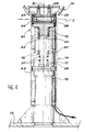
- a first angular measurement means 56 (FIG. 4) is interposed between mast 22 and pylon 18 to measure rotations around the B axis and a second way of angular measurement 58 is interposed between the mast 22 and the yoke 26, to measure rotations around the C axis.
- These two angular measurement means 56 and 58 are advantageously constituted by resolvers able to provide an angular measurement whose accuracy is about a hundredth of a degree.
- the first resolver 56 is placed at inside the pylon 18. It is therefore protected from high temperature prevailing inside the tunnel blower.
- the second resolver 58 is placed in the immediate vicinity of the wall of the machine in trial and it is only separated from very hot air surrounding only by the sheet of the cover 44.
- cooling means are advantageously provided for resolver 58.
- These cooling means include a tube 60 (illustrated schematically by a line in the figure 4) housed inside the cover 44 and allowing supply fresh air to resolver 58 while from a cooling system (no shown) located outside the wind tunnel 11.
- means of cooling are provided to cool each of the pivots 40 by which the jacks 28 are articulated on the yoke 36 fixed to the machine 10.
- the air flow rates of the cooling means are controlled by through calibrated collars located at the end tubes, at the level of the parts to be cooled (by example, 100g / s).
- These cooling means again include tubes 62 (illustrated schematically by lines in Figure 5) traveling inside the corresponding cover 46 thus inside the sleeve 48. At their end located outside the wind tunnel 11, these tubes 62 are also connected to a circuit cooling (not shown) delivering air cold. It should be noted that the tubes 62 comprise at less a telescopic or flexible part allowing them withstand variations in cylinder length hydraulic 28 corresponding rear supports 16.
- the invention is not limited to embodiment which has just been described as example, but covers all variants. So, it will be understood in particular that the front support and / or the rear supports could be placed not in below but above the machine under test, without departing from the scope of the invention.
- hydraulic cylinders 28 can be replaced by electric cylinders, provided that their relatively long answer be consistent with the simulated trajectory, or by pneumatic cylinders, provided that the volume occupied by them is not too penalizing.
- the means of articulation 20 can integrate a third degree of freedom from rotation orthogonal to the two degrees of freedom of rotation described.
Landscapes
- Physics & Mathematics (AREA)
- Fluid Mechanics (AREA)
- General Physics & Mathematics (AREA)
- Aerodynamic Tests, Hydrodynamic Tests, Wind Tunnels, And Water Tanks (AREA)
- Structures Of Non-Positive Displacement Pumps (AREA)
- Cleaning Of Streets, Tracks, Or Beaches (AREA)
- Wind Motors (AREA)
- Road Paving Machines (AREA)
Abstract
Description
- la figure 1 est une vue de côté qui représente schématiquement un engin volant à moteur monté dans un tunnel de soufflerie par un dispositif de montage conforme à l'invention ;
- la figure 2 est une vue de face illustrant schématiquement l'engin dans son état initial (trait plein), avec un angle d'incidence modifié (traite mixte) et avec une valeur de dérapage modifiée (trait tireté) ;
- la figure 3 est une vue en perspective du support avant caréné du dispositif de montage selon l'invention ;
- la figure 4 est une vue de face, à plus grande échelle et en coupe partielle, du support avant ; et
- la figure 5 est une vue de face, en coupe partielle, des supports arrière du dispositif de montage selon l'invention.
Claims (10)
- Dispositif (12) apte à supporter un engin volant (10) à moteur dans une soufflerie, pour étudier le comportement dudit engin (10), moteur allumé, sous différentes attitudes, ledit dispositif comprenant plusieurs supports articulés (14,16) aptes à relier l'engin (10) à une structure fixe (15) de la soufflerie, en des emplacements décalés par rapport à des zones d'écoulement d'air situées autour d'une partie avant de l'engin et en amont et en aval du moteur, l'un au moins desdits supports comportant des moyens de réglage de longueur (28), le dispositif étant caractérisé en ce que les moyens de réglage de longueur (28) sont reliés à des moyens de commande à distance (42) aptes à modifier en temps réel l'attitude de l'engin.
- Dispositif selon la revendication 1, dans lequel les supports comprennent un support avant (14), de longueur invariable, intégrant des moyens d'articulation (20) à au moins deux degrés de liberté de rotation autour de deux axes (B,C) orientés selon deux directions orthogonales entre elles et à un axe longitudinal (A) de l'engin, et deux supports arrière (16) intégrant chacun des moyens de réglage de longueur (28) et des liaisons à pivots (30,32).
- Dispositif selon la revendication 2, dans lequel le support avant (14) est orienté selon une direction sensiblement radiale par rapport à l'axe longitudinal de l'engin (10) et disposé dans un plan vertical (P2) passant par ledit axe longitudinal (A), les supports arrière (16) étant orientés selon des directions sensiblement radiales par rapport audit axe longitudinal (A) et disposés symétriquement par rapport audit plan vertical (P2), lorsque les deux supports arrière (16) sont dans un état initial.
- Dispositif selon la revendication 3, dans lequel, dans leur état initial, les deux supports arrière (16) forment avec ledit plan vertical (P2) un angle tel que le montage de l'engin (10) sur le dispositif (12) soit isostatique.
- Dispositif selon la revendication 4, dans lequel ledit angle est sensiblement égal à 45°.
- Dispositif selon l'une quelconque des revendications 3 à 5 dans lequel les supports arrière (16) sont décalés vers l'arrière d'environ un mètre par rapport au support avant (14), selon ledit axe longitudinal (A) .
- Dispositif selon l'une quelconque des revendications 2 à 6, dans lequel les moyens de réglage de longueur sont des vérins hydrauliques (28) asservis en longueur.
- Dispositif selon l'une quelconque des revendications 2 à 7, dans lequel chacun desdits supports (14,16) est placé à l'intérieur d'un capot caréné (44,46).
- Dispositif selon l'une quelconque des revendications 2 à 8, dans lequel des premiers moyens de refroidissement (62) sont prévus pour refroidir les liaisons à pivots (32) situées à proximité immédiate de l'engin.
- Dispositif selon l'une quelconque des revendications 2 à 9, dans lequel des moyens de mesure angulaire (56,58) sont associés aux moyens d'articulation (20), des deuxièmes moyens de refroidissement (60) étant prévus pour refroidir les moyens de mesure angulaire (58) situés à proximité immédiate de l'engin.
Applications Claiming Priority (2)
| Application Number | Priority Date | Filing Date | Title |
|---|---|---|---|
| FR0007927 | 2000-06-21 | ||
| FR0007927A FR2810734B1 (fr) | 2000-06-21 | 2000-06-21 | Dispositif de support d'un engin volant a moteur dans une soufflerie |
Publications (2)
| Publication Number | Publication Date |
|---|---|
| EP1167941A1 true EP1167941A1 (fr) | 2002-01-02 |
| EP1167941B1 EP1167941B1 (fr) | 2009-04-08 |
Family
ID=8851496
Family Applications (1)
| Application Number | Title | Priority Date | Filing Date |
|---|---|---|---|
| EP01401626A Expired - Lifetime EP1167941B1 (fr) | 2000-06-21 | 2001-06-20 | Dispositif de support d'un engin volant à moteur dans une soufflerie |
Country Status (9)
| Country | Link |
|---|---|
| US (1) | US6571618B2 (fr) |
| EP (1) | EP1167941B1 (fr) |
| JP (1) | JP2002089368A (fr) |
| AT (1) | ATE428107T1 (fr) |
| CA (1) | CA2350150C (fr) |
| DE (1) | DE60138244D1 (fr) |
| ES (1) | ES2326618T3 (fr) |
| FR (1) | FR2810734B1 (fr) |
| RU (1) | RU2271527C2 (fr) |
Cited By (1)
| Publication number | Priority date | Publication date | Assignee | Title |
|---|---|---|---|---|
| WO2007020030A1 (fr) * | 2005-08-12 | 2007-02-22 | Airbus Deutschland Gmbh | Soufflerie presentant un modele agence a l'interieur, en particulier un modele d'aeronef, pour l'acquisition et l'evaluation d'une pluralite de donnees de mesure, et procede associe |
Families Citing this family (15)
| Publication number | Priority date | Publication date | Assignee | Title |
|---|---|---|---|---|
| FR2864228B1 (fr) * | 2003-12-19 | 2006-04-28 | Airbus France | Dispositif de protection d'une sonde solidaire d'une paroi e xterne d'un avion |
| US7234348B2 (en) * | 2004-03-11 | 2007-06-26 | Nike, Inc. | Testing apparatus |
| GB0500502D0 (en) * | 2005-01-11 | 2005-02-16 | Isis Innovation | Evaluation of the performance of systems |
| US7254998B2 (en) * | 2005-10-31 | 2007-08-14 | The Boeing Company | Method for determining drag characteristics of aircraft and system for performing the method |
| DE102007062736B3 (de) * | 2007-12-27 | 2009-10-08 | Airbus Deutschland Gmbh | Vorrichtung zur schwenkbaren Befestigung einer Wirkfläche, insbesondere eines Spoilers an einem Windkanalmodell eines Flugzeugs |
| JP5611120B2 (ja) * | 2011-05-23 | 2014-10-22 | 三菱航空機株式会社 | 雷撃試験装置、雷撃試験システム、および雷撃試験方法 |
| CN108645591B (zh) * | 2018-06-27 | 2024-02-20 | 中国空气动力研究与发展中心高速空气动力研究所 | 一种用于跨声速风洞中扁平融合体飞机的v型尾支撑装置 |
| CN111220342B (zh) * | 2020-03-18 | 2024-04-05 | 中国空气动力研究与发展中心高速空气动力研究所 | 一种高速风洞内埋试验模型投放机构 |
| CN111896215B (zh) * | 2020-08-05 | 2025-02-07 | 中国航空工业集团公司哈尔滨空气动力研究所 | 一种释放风洞试验模型两个刚体自由度的模型支撑装置 |
| CN112161528B (zh) * | 2020-09-07 | 2023-01-13 | 蓝箭航天空间科技股份有限公司 | 一种用于火箭装配的调姿装置 |
| CN114509234B (zh) * | 2022-04-20 | 2022-07-05 | 中国空气动力研究与发展中心超高速空气动力研究所 | 用于高超声速风洞混合加热气体喷流供气的柔性管路装置 |
| CN115127771B (zh) * | 2022-07-22 | 2024-03-29 | 中国空气动力研究与发展中心高速空气动力研究所 | 一种高速风洞横向非对称弱扰动波检测与扰动源定位方法 |
| CN115585978B (zh) * | 2022-12-09 | 2023-03-14 | 中国航空工业集团公司沈阳空气动力研究所 | 一种用于跨声速风洞双自由度运动的试验装置 |
| CN118010292B (zh) * | 2024-04-09 | 2024-06-18 | 中国空气动力研究与发展中心高速空气动力研究所 | 亚跨声速进发直连风洞试验模型支撑装置及设计方法 |
| CN118961131B (zh) * | 2024-10-15 | 2024-12-17 | 中国空气动力研究与发展中心高速空气动力研究所 | 一种风洞专用的连续变侧滑机构 |
Citations (3)
| Publication number | Priority date | Publication date | Assignee | Title |
|---|---|---|---|---|
| DE1172875B (de) * | 1962-10-15 | 1964-06-25 | Ernst Heinkel Flugzeugbau G M | Vorrichtung zur elastischen Abstuetzung eines Versuchskoerpers |
| US4920791A (en) * | 1988-10-14 | 1990-05-01 | General Dynamics Corporation, Convair Division | Wind tunnel model support and attitude control |
| US5370349A (en) * | 1992-03-06 | 1994-12-06 | Aerospatiale Societe Nationale Industrielle | Structure for positioning and stabilizing an object at a given point within a three-dimensional coordinate system |
Family Cites Families (6)
| Publication number | Priority date | Publication date | Assignee | Title |
|---|---|---|---|---|
| GB820061A (en) * | 1957-04-09 | 1959-09-16 | Boeing Co | Wind tunnel model support |
| FR2159548A5 (fr) | 1971-11-02 | 1973-06-22 | Onera (Off Nat Aerospatiale) | |
| FR2641378B1 (fr) | 1988-12-30 | 1991-04-19 | Framatome Sa | Dispositif de deplacement d'une maquette dans un tunnel de soufflerie |
| JPH04120434A (ja) * | 1990-09-11 | 1992-04-21 | Mitsubishi Heavy Ind Ltd | 風洞試験装置の模型支持機構 |
| JP2694263B2 (ja) * | 1994-08-23 | 1997-12-24 | 科学技術庁航空宇宙技術研究所長 | 三次元気流発生装置、及び該装置を使用した航空機の飛行制御系検証方法並びに飛行モーションシミュレータ |
| DE19815312C1 (de) * | 1998-04-06 | 1999-11-18 | Daimler Chrysler Ag | Verfahren und Vorrichtung zum genauen Positionieren, insbesondere eines Fahrzeugs, in einem Windkanal |
-
2000
- 2000-06-21 FR FR0007927A patent/FR2810734B1/fr not_active Expired - Lifetime
-
2001
- 2001-06-12 CA CA002350150A patent/CA2350150C/fr not_active Expired - Lifetime
- 2001-06-20 RU RU2001117407/11A patent/RU2271527C2/ru active
- 2001-06-20 ES ES01401626T patent/ES2326618T3/es not_active Expired - Lifetime
- 2001-06-20 US US09/884,161 patent/US6571618B2/en not_active Expired - Lifetime
- 2001-06-20 DE DE60138244T patent/DE60138244D1/de not_active Expired - Lifetime
- 2001-06-20 EP EP01401626A patent/EP1167941B1/fr not_active Expired - Lifetime
- 2001-06-20 JP JP2001187072A patent/JP2002089368A/ja not_active Withdrawn
- 2001-06-20 AT AT01401626T patent/ATE428107T1/de not_active IP Right Cessation
Patent Citations (3)
| Publication number | Priority date | Publication date | Assignee | Title |
|---|---|---|---|---|
| DE1172875B (de) * | 1962-10-15 | 1964-06-25 | Ernst Heinkel Flugzeugbau G M | Vorrichtung zur elastischen Abstuetzung eines Versuchskoerpers |
| US4920791A (en) * | 1988-10-14 | 1990-05-01 | General Dynamics Corporation, Convair Division | Wind tunnel model support and attitude control |
| US5370349A (en) * | 1992-03-06 | 1994-12-06 | Aerospatiale Societe Nationale Industrielle | Structure for positioning and stabilizing an object at a given point within a three-dimensional coordinate system |
Cited By (2)
| Publication number | Priority date | Publication date | Assignee | Title |
|---|---|---|---|---|
| WO2007020030A1 (fr) * | 2005-08-12 | 2007-02-22 | Airbus Deutschland Gmbh | Soufflerie presentant un modele agence a l'interieur, en particulier un modele d'aeronef, pour l'acquisition et l'evaluation d'une pluralite de donnees de mesure, et procede associe |
| US7987707B2 (en) | 2005-08-12 | 2011-08-02 | Airbus Deutschland Gmbh | Wind tunnel with a model arranged therein, particularly a model of an aircraft, for acquiring and evaluating a plurality of measuring data, as well as method |
Also Published As
| Publication number | Publication date |
|---|---|
| FR2810734B1 (fr) | 2002-10-04 |
| US6571618B2 (en) | 2003-06-03 |
| RU2271527C2 (ru) | 2006-03-10 |
| DE60138244D1 (de) | 2009-05-20 |
| FR2810734A1 (fr) | 2001-12-28 |
| CA2350150C (fr) | 2007-09-25 |
| JP2002089368A (ja) | 2002-03-27 |
| EP1167941B1 (fr) | 2009-04-08 |
| CA2350150A1 (fr) | 2001-12-21 |
| ES2326618T3 (es) | 2009-10-16 |
| ATE428107T1 (de) | 2009-04-15 |
| US20020023484A1 (en) | 2002-02-28 |
Similar Documents
| Publication | Publication Date | Title |
|---|---|---|
| CA2350150C (fr) | Dispositif de support d'un engin volant a moteur dans une soufflerie | |
| EP2030892B1 (fr) | Pylone de suspension d'un moteur sous une aile d'avion | |
| EP4041628B1 (fr) | Système de commande de calage cyclique de pales | |
| EP2526286B1 (fr) | Dispositif pour commander le mouvement d'une vanne-fourreau de machine hydraulique et machine hydraulique comportant un tel dispositif | |
| EP0378480B1 (fr) | Engin pour inspecter l'intérieur des canalisations | |
| CA2923212A1 (fr) | Dispositif d'alimentation en fluide hydraulique d'un verin et mecanisme de commande de pas des pales d'une helice de turbomoteur comportant le verin | |
| WO2019002725A1 (fr) | Procédé d'assemblage d'une turbomachine | |
| FR2992292A1 (fr) | Dispositif et procede d'assemblage d'une structure fixe d'inverseur de poussee d'un ensemble propulsif d'aeronef | |
| EP1491725B1 (fr) | Dispositif de guidage d'une aube à angle de calage variable | |
| FR3037039A1 (fr) | Dispositif de verrouillage de capots pivotants d’un inverseur de poussee | |
| FR3098788A1 (fr) | Module de turbomachine pour une hélice à calage variable des pales et turbomachine le comportant | |
| CA2932998A1 (fr) | Compresseur de turbomachine, en particulier de turbopropulseur ou de turboreacteur d'avion | |
| FR3057543A1 (fr) | Turbomachine a axes decales horizontalement | |
| FR3126019A1 (fr) | Module de soufflante a pales a calage variable | |
| CA2816255A1 (fr) | Nacelle pour un turboreacteur double flux d'un aeronef | |
| FR3054006A1 (fr) | Ensemble pour la commande d'aubes a calage variable dans une turbomachine | |
| EP3428055B1 (fr) | Procédé et dispositif de détermination de la direction et de l'amplitude d'un effort appliqué sur une nacelle de propulsion pour bateau | |
| FR2993932A1 (fr) | Dispositif d'entrainement de volets notamment pour tuyere adaptative | |
| FR3095193A1 (fr) | Procédé d’utilisation d’une entrée d’air de nacelle de turboréacteur comprenant une lèvre d’entrée d’air comprenant une portion mobile pour favoriser une phase d’inversion de poussée | |
| FR3060661A1 (fr) | Turbopropulseur a arbre d'helice deporte comprenant une boite d'accessoires | |
| CA2382390C (fr) | Manche a air et engin volant, en particulier un missile, muni d'une telle manche a air | |
| FR3088683A1 (fr) | Ensemble pour turbomachine d'aeronef comportant un systeme a lubrifier ainsi qu'un dispositif ameliore d'injection de lubrifiant | |
| FR2480863A1 (fr) | Transformation d'un mouvement circulaire en deplacement rectiligne | |
| EP4295025B1 (fr) | Partie arrière de turboreacteur comprenant une tuyère à loi a9/a8 étendue | |
| EP2261588B1 (fr) | Dispositif de pointage en gisement d'une tourelle |
Legal Events
| Date | Code | Title | Description |
|---|---|---|---|
| PUAI | Public reference made under article 153(3) epc to a published international application that has entered the european phase |
Free format text: ORIGINAL CODE: 0009012 |
|
| AK | Designated contracting states |
Kind code of ref document: A1 Designated state(s): AT BE CH CY DE DK ES FI FR GB GR IE IT LI LU MC NL PT SE TR |
|
| AX | Request for extension of the european patent |
Free format text: AL;LT;LV;MK;RO;SI |
|
| 17P | Request for examination filed |
Effective date: 20020322 |
|
| AKX | Designation fees paid |
Free format text: AT BE CH CY DE DK ES FI FR GB GR IE IT LI LU MC NL PT SE TR |
|
| 17Q | First examination report despatched |
Effective date: 20071214 |
|
| GRAP | Despatch of communication of intention to grant a patent |
Free format text: ORIGINAL CODE: EPIDOSNIGR1 |
|
| GRAS | Grant fee paid |
Free format text: ORIGINAL CODE: EPIDOSNIGR3 |
|
| GRAA | (expected) grant |
Free format text: ORIGINAL CODE: 0009210 |
|
| AK | Designated contracting states |
Kind code of ref document: B1 Designated state(s): AT BE CH CY DE DK ES FI FR GB GR IE IT LI LU MC NL PT SE TR |
|
| REG | Reference to a national code |
Ref country code: GB Ref legal event code: FG4D Free format text: NOT ENGLISH |
|
| REG | Reference to a national code |
Ref country code: CH Ref legal event code: EP |
|
| REG | Reference to a national code |
Ref country code: IE Ref legal event code: FG4D |
|
| REF | Corresponds to: |
Ref document number: 60138244 Country of ref document: DE Date of ref document: 20090520 Kind code of ref document: P |
|
| REG | Reference to a national code |
Ref country code: SE Ref legal event code: TRGR |
|
| NLV1 | Nl: lapsed or annulled due to failure to fulfill the requirements of art. 29p and 29m of the patents act | ||
| RAP2 | Party data changed (patent owner data changed or rights of a patent transferred) |
Owner name: MBDAM |
|
| REG | Reference to a national code |
Ref country code: ES Ref legal event code: FG2A Ref document number: 2326618 Country of ref document: ES Kind code of ref document: T3 |
|
| RAP2 | Party data changed (patent owner data changed or rights of a patent transferred) |
Owner name: MBDA FRANCE |
|
| REG | Reference to a national code |
Ref country code: IE Ref legal event code: FD4D |
|
| PG25 | Lapsed in a contracting state [announced via postgrant information from national office to epo] |
Ref country code: FI Free format text: LAPSE BECAUSE OF FAILURE TO SUBMIT A TRANSLATION OF THE DESCRIPTION OR TO PAY THE FEE WITHIN THE PRESCRIBED TIME-LIMIT Effective date: 20090408 Ref country code: PT Free format text: LAPSE BECAUSE OF FAILURE TO SUBMIT A TRANSLATION OF THE DESCRIPTION OR TO PAY THE FEE WITHIN THE PRESCRIBED TIME-LIMIT Effective date: 20090908 Ref country code: AT Free format text: LAPSE BECAUSE OF FAILURE TO SUBMIT A TRANSLATION OF THE DESCRIPTION OR TO PAY THE FEE WITHIN THE PRESCRIBED TIME-LIMIT Effective date: 20090408 |
|
| PG25 | Lapsed in a contracting state [announced via postgrant information from national office to epo] |
Ref country code: NL Free format text: LAPSE BECAUSE OF FAILURE TO SUBMIT A TRANSLATION OF THE DESCRIPTION OR TO PAY THE FEE WITHIN THE PRESCRIBED TIME-LIMIT Effective date: 20090408 |
|
| BERE | Be: lapsed |
Owner name: AEROSPATIALE MATRA MISSILES Effective date: 20090630 |
|
| PG25 | Lapsed in a contracting state [announced via postgrant information from national office to epo] |
Ref country code: MC Free format text: LAPSE BECAUSE OF NON-PAYMENT OF DUE FEES Effective date: 20090630 Ref country code: DK Free format text: LAPSE BECAUSE OF FAILURE TO SUBMIT A TRANSLATION OF THE DESCRIPTION OR TO PAY THE FEE WITHIN THE PRESCRIBED TIME-LIMIT Effective date: 20090408 Ref country code: IE Free format text: LAPSE BECAUSE OF FAILURE TO SUBMIT A TRANSLATION OF THE DESCRIPTION OR TO PAY THE FEE WITHIN THE PRESCRIBED TIME-LIMIT Effective date: 20090408 |
|
| REG | Reference to a national code |
Ref country code: CH Ref legal event code: PL |
|
| PLBE | No opposition filed within time limit |
Free format text: ORIGINAL CODE: 0009261 |
|
| STAA | Information on the status of an ep patent application or granted ep patent |
Free format text: STATUS: NO OPPOSITION FILED WITHIN TIME LIMIT |
|
| 26N | No opposition filed |
Effective date: 20100111 |
|
| REG | Reference to a national code |
Ref country code: FR Ref legal event code: ST Effective date: 20100226 |
|
| PG25 | Lapsed in a contracting state [announced via postgrant information from national office to epo] |
Ref country code: CH Free format text: LAPSE BECAUSE OF NON-PAYMENT OF DUE FEES Effective date: 20090630 Ref country code: FR Free format text: LAPSE BECAUSE OF NON-PAYMENT OF DUE FEES Effective date: 20090630 Ref country code: LI Free format text: LAPSE BECAUSE OF NON-PAYMENT OF DUE FEES Effective date: 20090630 |
|
| PG25 | Lapsed in a contracting state [announced via postgrant information from national office to epo] |
Ref country code: BE Free format text: LAPSE BECAUSE OF NON-PAYMENT OF DUE FEES Effective date: 20090630 |
|
| PG25 | Lapsed in a contracting state [announced via postgrant information from national office to epo] |
Ref country code: GR Free format text: LAPSE BECAUSE OF FAILURE TO SUBMIT A TRANSLATION OF THE DESCRIPTION OR TO PAY THE FEE WITHIN THE PRESCRIBED TIME-LIMIT Effective date: 20090709 |
|
| PG25 | Lapsed in a contracting state [announced via postgrant information from national office to epo] |
Ref country code: LU Free format text: LAPSE BECAUSE OF NON-PAYMENT OF DUE FEES Effective date: 20090620 |
|
| PG25 | Lapsed in a contracting state [announced via postgrant information from national office to epo] |
Ref country code: TR Free format text: LAPSE BECAUSE OF FAILURE TO SUBMIT A TRANSLATION OF THE DESCRIPTION OR TO PAY THE FEE WITHIN THE PRESCRIBED TIME-LIMIT Effective date: 20090408 |
|
| PG25 | Lapsed in a contracting state [announced via postgrant information from national office to epo] |
Ref country code: CY Free format text: LAPSE BECAUSE OF FAILURE TO SUBMIT A TRANSLATION OF THE DESCRIPTION OR TO PAY THE FEE WITHIN THE PRESCRIBED TIME-LIMIT Effective date: 20090408 |
|
| PGFP | Annual fee paid to national office [announced via postgrant information from national office to epo] |
Ref country code: DE Payment date: 20200612 Year of fee payment: 20 |
|
| PGFP | Annual fee paid to national office [announced via postgrant information from national office to epo] |
Ref country code: IT Payment date: 20200619 Year of fee payment: 20 Ref country code: SE Payment date: 20200622 Year of fee payment: 20 Ref country code: GB Payment date: 20200619 Year of fee payment: 20 |
|
| PGFP | Annual fee paid to national office [announced via postgrant information from national office to epo] |
Ref country code: ES Payment date: 20200713 Year of fee payment: 20 |
|
| REG | Reference to a national code |
Ref country code: DE Ref legal event code: R071 Ref document number: 60138244 Country of ref document: DE |
|
| REG | Reference to a national code |
Ref country code: GB Ref legal event code: PE20 Expiry date: 20210619 |
|
| REG | Reference to a national code |
Ref country code: SE Ref legal event code: EUG |
|
| PG25 | Lapsed in a contracting state [announced via postgrant information from national office to epo] |
Ref country code: GB Free format text: LAPSE BECAUSE OF EXPIRATION OF PROTECTION Effective date: 20210619 |
|
| REG | Reference to a national code |
Ref country code: ES Ref legal event code: FD2A Effective date: 20211105 |
|
| PG25 | Lapsed in a contracting state [announced via postgrant information from national office to epo] |
Ref country code: ES Free format text: LAPSE BECAUSE OF EXPIRATION OF PROTECTION Effective date: 20210621 |