EP1167774A2 - Pump motor for vehicle - Google Patents
Pump motor for vehicle Download PDFInfo
- Publication number
- EP1167774A2 EP1167774A2 EP01401720A EP01401720A EP1167774A2 EP 1167774 A2 EP1167774 A2 EP 1167774A2 EP 01401720 A EP01401720 A EP 01401720A EP 01401720 A EP01401720 A EP 01401720A EP 1167774 A2 EP1167774 A2 EP 1167774A2
- Authority
- EP
- European Patent Office
- Prior art keywords
- housing
- motor
- end side
- pump
- hole
- Prior art date
- Legal status (The legal status is an assumption and is not a legal conclusion. Google has not performed a legal analysis and makes no representation as to the accuracy of the status listed.)
- Granted
Links
Images


Classifications
-
- F—MECHANICAL ENGINEERING; LIGHTING; HEATING; WEAPONS; BLASTING
- F04—POSITIVE - DISPLACEMENT MACHINES FOR LIQUIDS; PUMPS FOR LIQUIDS OR ELASTIC FLUIDS
- F04D—NON-POSITIVE-DISPLACEMENT PUMPS
- F04D13/00—Pumping installations or systems
- F04D13/02—Units comprising pumps and their driving means
- F04D13/06—Units comprising pumps and their driving means the pump being electrically driven
-
- F—MECHANICAL ENGINEERING; LIGHTING; HEATING; WEAPONS; BLASTING
- F04—POSITIVE - DISPLACEMENT MACHINES FOR LIQUIDS; PUMPS FOR LIQUIDS OR ELASTIC FLUIDS
- F04D—NON-POSITIVE-DISPLACEMENT PUMPS
- F04D29/00—Details, component parts, or accessories
- F04D29/58—Cooling; Heating; Diminishing heat transfer
- F04D29/586—Cooling; Heating; Diminishing heat transfer specially adapted for liquid pumps
- F04D29/588—Cooling; Heating; Diminishing heat transfer specially adapted for liquid pumps cooling or heating the machine
Definitions
- the invention relates to a pump motor for a vehicle used for the purpose of supplying a washer liquid to a wiper apparatus mounted in a vehicle.
- a pump motor housing there are some pump motor housings in which a motor chamber is formed at the tip end side (upper side) via a partitioning wall, and a pump chamber is formed at the base end side (lower side).
- a ventilation hole by which the inner atmosphere communicates with the outer atmosphere in order to make the inner and outer atmospheric air pressure uniform, in the motor chamber, but, at the same time, not permitting water to flow in.
- Such a motor housing having a ventilation hole which communicates from the pump chamber side, i.e., adjacent the side of the pump chamber but external thereto, located at the lower side of the pump motor housing to the upper side motor chamber, the inner and outer atmospheric air being exchanged while avoiding invasion of water into the motor chamber.
- a housing for example, is found in JP-Y2-62-20720.
- a ventilation hole that reaches from the outer diametrical portion at the base end side of the housing to the motor chamber is formed so as to bypass the pump chamber, and the ventilation hole is further opposed to a through hole opened at the outer diametrical portion of a covering member that seals and encloses the pump chamber, wherein the inner and outer atmospheric air of the motor chamber are caused to communicate with each other through the ventilation hole and through hole.
- the ventilation hole will be formed by inserting a draft die for the ventilation hole from the base end side, being the pump chamber side of the housing, to the motor chamber side.
- the draft die is inserted almost parallel to the cylindrical center of a rough cylinder that forms the outer diameter of the housing. Therefore, it is necessary that the outer diameter of the motor chamber be made larger than the outer diameter of the pump chamber so that the ventilation hole penetrates from the outer diametrical side at the base end side of the pump chamber to the motor chamber.
- the invention was developed in order to solve the above problems in view of the above-described situations. It is therefore an object of the invention to provide a pump motor for a vehicle accommodated in a housing in which a motor chamber supporting a motor shaft is formed at the tip end side thereof and a pump chamber is formed at the base end side thereof via a partitioning wall, wherein, when forming a ventilation port or hole for communicating the interior of the motor chamber with the exterior thereof for venting so that the ventilation hole bypasses the pump chamber from the base end side of the housing to enter the motor chamber, an outer hole opened to the base end side of the housing communicates with an inner hole that is located closer to the axial center of the motor shaft than is the outer hole and is opened to the interior of the motor chamber, that is, the ventilation hole has a slope from the outer hole to the inner hole such that the outer hole is further from the axial center than is the inner hole.
- the outer diameter opposed to the motor chamber of the housing can be formed to be small.
- the inner hole and outer hole are produced by using split type upper and lower metal dies, and the communication between the inner hole and outer hole is formed through the fitting surface between the upper and lower metal dies.
- the ventilation hole is formed so as to incline and reach from the base end side of a projection, which protrudes from and is formed at the outer circumferential surface of the housing, opposite to the pump chamber, to the interior of the motor chamber.
- a plurality of ventilation holes are formed in the circumferential direction of the housing, the respective ventilation holes are parallel to each other, and are formed in parallel to a plane passing through the motor shaft and a point midway between the outer holes of the ventilation holes.
- the projection according to the invention is formed adjacent to the circumferential direction with respect to an intake hole formed so as to protrude outward from the outer circumferential surface of the housing.
- a sealing recessed groove to seal the pump chamber, is formed at the base end side of the housing, an inclined recessed groove inclined toward the inner side is formed adjacent to the outside of the sealing recessed groove, and the ventilation holes are positioned at both ends in the circumferential direction of the inclined recessed groove and are formed along the inclination of the inclined recessed groove.
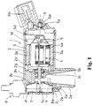
- a pump motor 1 supplies a washer liquid in a washer tank (not illustrated) to washer nozzles provided at a wiper apparatus.
- a housing 2, in which the pump motor 1 is accommodated, is formed to be roughly cylindrical and is integrally formed using metal dies.
- a funnel-shaped partitioning wall 2b In the housing 2, a funnel-shaped partitioning wall 2b, the tip end side of which is positioned deep in the cylinder in a state where it is continuous from the base end side thereof 2a (the end face, which is the underside of the housing 2 with the pump motor attached), whereby the tip end side is partitioned from the base end side.
- the motor chamber M is set to be on the tip end side and the pump chamber P is set to be on the base end side.
- the inner diameter at the motor chamber M side is set to be almost the same dimension as at the pump chamber P side.
- a yoke 3 is integrally secured on the inner circumferential surface of the above-described motor chamber M, and a pair of permanent magnets 3a are attached to and fixed on the inner circumferential surface of the yoke 3.
- An armature 4 is disposed in a state where the outer circumferential surface of the armature core 4a is opposed to and in the vicinity of the inner circumferential surface of the permanent magnets 3.
- the tip end 5a of the armature shaft (motor shaft) 5, that constitutes the armature 4, is pivotally supported on a front cover 6, which covers the tip end of the housing 2, via a bearing 6a, and the intermediate portion 5b thereof is pivotally supported at a cylindrical pivotal supporting part 2c, which is formed at the partitioning wall 2b, via bearing 2d, wherein the armature 4 is supported so as to freely rotate in the motor chamber M.
- a commutator 5d is fixed on the armature shaft 5, and an electric connection part 6b is formed integrally with the front cover 6.
- the base end portion 5c of the armature shaft 5 protrudes from the pivotal supporting part 2c of the housing into the pump chamber P, and one-sided chamfering is employed at the base end portion 5c of the protruded armature shaft 5.
- the impeller 7 is attached to the one-sided chamfered part, and the impeller 7 is established so as to rotate integrally with clockwise and counterclockwise rotations of the armature shaft 5.
- an intake port 2e that communicates with the pump chamber P side and sucks a washer liquid into the pump chamber P is formed so as to protrude outward in the vicinity of the base end side 2a at the outer circumferential surface of the housing 2.
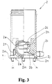
- Thick (solid) projections 2f protrude from the outer circumferential surface of the housing 2, extend in a direction parallel to the axis of the armature shaft 5, and are formed so as to be continuous from the base end side 2a of the housing.
- the projections 2f are on the outer circumferential surface of the housing 2 and positioned at each side of the intake port 2e in the circumferential direction.
- the length of the projections 2f in the direction of the armature shaft 5 is made short so as to be set to a length which is slightly longer than the tip end side portion of the partitioning wall 2b that partitions the inside of the cylinder of the housing 2, and the motor chamber M side of the housing 2 remains cylindrical.
- the section between the projections 2f that is, the portion of the housing 2 surrounding, or adjacent to, the outwardly extending intake port 2e at the base end side surface 2a of the housing 2, is thickly formed and connects the projections 2f together.
- the portion of the housing 2 is thickened so that it protrudes outward from the base end to the intake port 2e, thereby forming a thick extension portion E.
- the thick extension portion E protrudes outward, partially surrounds the intake port 2e at the base end side surface 2a of the housing 2 and is lengthened in the circumferential direction between the projections 2f.
- a sealing member 2g is disposed at the base end side of the pivotal supporting portion 2c.
- the sealing member 2g is set so as to seal the pump chamber P and intake port 2e from the motor chamber M.
- a plurality of reinforcement ribs 2h are formed in the circumferential direction at the tip end side (motor chamber M side) of the partitioning wall 2b.
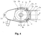
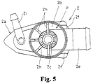
- the base end side 2a of the housing has a projection extending to the side opposite to the intake port 2e side (Figs. 4 and 5), wherein a discharge port 2i is formed so as to protrude outward, and a washer liquid sucked from the intake port 2e into the pump chamber P is transferred to the discharge port 2i side by the rotation of the impeller 7.
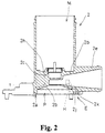
- a sealing recessed groove 2j that encloses the pump chamber P and seals the pump chamber P, as described later, is formed to be recessed at the outer diametrical portion at the base end side 2a. Further, an elongated inclined recessed groove 2k is formed to be recessed in the circumferential direction within the thick extension portion E and positioned outside the sealing recessed groove 2j in a state where the inclined recessed groove 2k is adjacent to the outer edge of the sealing recessed groove 2j.
- the groove direction, or depth, of the sealing recessed groove 2j is oriented in the direction of the armature shaft 5 and formed in parallel thereto
- the grove direction of the inclined recessed groove 2k is formed as an inclined groove with the groove inner side positioned closer to the armature shaft 5 and the groove opening side, at the base end side 2a, positioned further from the armature shaft 5, i.e., the inclined recessed groove 2k is inclined toward the inner diametrical side.
- a clearance portion 2m is positioned at a roughly central part in the circumferential direction of the housing surface at the underside of the intake port 2e, and is formed to be notched at the groove side piece (side wall) that constitutes the inclined recessed groove 2k.
- Ventilation holes H are positioned at both ends, in the circumferential direction, of the inclined recessed groove 2k, that is, at the part where the projection 2f of the housing 2 is formed, and are opened along the direction of the inclined groove of the inclined recessed groove 2k.
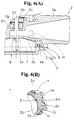
- the ventilation holes H are formed by inserting the upper metal die H (to be described with the same reference symbol as that of the ventilation holes for the convenience of description), which is shown with broken lines in Figs. 1 and 3, from the motor chamber M when molding a pump motor housing.
- a lower metal die is inserted from the base end side 2a of the housing 2 in order to form the inclined recessed groove
- the upper metal die is inserted from the upper side (motor chamber M side) so that the upper metal die H, in which a pair of projections are formed opposite to the part where the projection 2f of the inclined recessed groove 2k is formed, is brought into contact with the corresponding lower metal die, whereby an outer hole opened in the base end side 2a of the housing and an inner hole opened inside the motor chamber M are caused to communicate with each other so that the ventilation hole H is formed.
- the ventilation hole H is formed so that the inner hole is located nearer to a plane W (Fig.
- the ventilation hole H passing through the axial center of the armature shaft 5 than the outer hole, that is, the ventilation hole H is further inclined toward the inner side, actually towards the plane W passing through the axial center and transverse to the longitudinal axis of the intake port 2e, whereby the ventilation hole H is set so as to reach the motor chamber M, bypassing the pump chamber P.
- the above-described two ventilation holes H are formed by a pair of projections secured at the single upper metal die with respect to the lower metal die. Therefore, the direction of the respective ventilation holes H becomes parallel to the direction of the inclined recessed groove 2k so as to extend from the inclined groove, and are parallel to the plane Z passing through the armature shaft and through a point (A) between and equal distance from the ventilation holes H.
- the air passage is constructed to have a labyrinth-like structure so that the outer atmospheric air flowing through the clearance portion 2m does not directly enter the ventilation holes H, whereby water is prevented from invading the motor chamber M.
- an end cover 8 covers the base end side 2a of the housing so that it itself is abutted against the base end side 2a.
- An engagement projection 8a, to seal the pump chamber P, is formed at the tip end side (upper side) of the end cover 8 so that it is fitted to the sealing recessed groove 2j at the housing 2 side along with the sealing material.
- an engagement hole (not illustrated) is formed at three points in the circumferential direction, and each engagement projection 2n protruding from the base end side 2a of the housing is constructed so as to be fitted to and engaged in a one of the above-described engagement holes, thereby positioning the housing 2 and end cover 8.
- a washer liquid stored in a tank (not illustrated) is caused to flow from the intake port 2e of the pump motor 1 into the pump chamber P, and is discharged from the discharge port 2i.
- the ventilation with the outer atmospheric air into the motor chamber M is carried out by an air passage from the clearance portion 2m positioned and formed outside the base end side 2a of the housing to the inside of the motor chamber M through the inclined recessed groove 2k via the ventilation holes H.
- the ventilation holes H are formed so that the projections 2f, formed on the outer circumferential surface opposed to the pump chamber P of the housing 2, become shorter in the direction of the armature shaft 5, the metal die H is inclined inwardly and inserted so as to reach from the base end side 2a to the inside of the motor chamber M at the projection 2f, and the inner hole of the ventilation hole H is positioned nearer to the plane W than the outer hole thereof (see Fig. 9). If B is the inner hole's distance to the plane W and C is the outer hole's distance to the plane W, then B ⁇ C.
- the motor chamber M can be kept small in diameter and cylindrical at the tip end side part of the housing 2, that is, at the motor chamber M side, unlike the prior art type in which a metal die is inserted in parallel to the armature shaft to form ventilation holes, it is not necessary to make the housing large in diameter over the full length thereof, whereby the pump motor can be made compact.
- projections 2f for forming ventilation holes H are integrally formed at the outer circumference of the housing 2 corresponding to the pump chamber P, and the upper and lower metal dies are inclined and inserted between the outer diameter side of and the inner diameter side of the motor chamber M at the corresponding projections 2f, whereby ventilation holes H in which the inner hole is positioned nearer to the plane W than the outer hole can be formed, and the outer diameter of the housing 2 can be kept small in diameter.
- the projections 2f are formed so as to abut on the intake port 2e in the circumferential direction, which is formed at and protruded from the outer circumferential side of the cylinder of the housing 2, there is no inconvenience of a worsening of the space utility in attaching the pump motor 1 due to the formation of the projections 2f at the corresponding portion.
- the base end side 2a can be formed to allow the projections extending therefrom to be provided.
- the base end side 2a By making the base end side 2a roughly elliptical, the overall width produced by the projections can be reduced.
- the outer diameter of the end cover 8 can be formed to be elliptical, and reliability in the sealing of the pump chamber P and end cover 8 can be improved.
- a sealing member may be circularly filled in the case where the front cover 6 and motor chamber M are assembled to be sealed, and automated sealing work can be further simplified.
- the embodiment is constructed so that, using the upper and lower metal dies, the fitting surfaces of the metal dies are devised to communicate the outer hole and the inner hole of the ventilation holes H with each other, the structure of the metal dies can be simplified without becoming complicated.
- the upper metal die is formed so as to abut on the lower metal die used to form the inclined recessed groove 2k, concurrent uses of metal dies can be achieved, thereby reducing the number of parts of the metal dies.
- a plurality of ventilation holes H are formed in the circumferential direction of the housing 2.
- ventilation holes H which are parallel to each other, and are formed by using a single metal die, further simplification of the metal dies can be achieved.
- the embodiment is structured so that outer atmospheric air flowing into the ventilation holes H is caused to flow in through the clearance portion 2m located at a roughly central position in the circumferential direction of the extension portion E formed at the outer diameter side of the base end side 2a of the housing, and reaches the ventilation holes H via the inclined recessed groove 2k in the circumferential direction. Therefore, the air passage is constructed with a labyrinth-like structure, wherein the waterproof feature can be made further excellent.
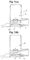
- the present invention is not limited to the above-described embodiment. It may be constructed as in the second embodiment shown in Figs. 7(A) and 8.
- the ventilation holes H are folded like a crank.
- the ventilation holes are die-molded in a state where the planes X and Y of the upper and lower metal dies are brought into contact with each other (Fig. 8(B)), whereby the inner hole is positioned nearer to the axial center side of the motor shaft than the outer hole in the motor chamber M side and opened thereat while the outer hole is positioned at and opened at the outside (outer diameter) of the base end side 9a of the housing 9.
- the outer diameter of the motor chamber M can be kept small.
- the invention may be constructed as in the third embodiment as shown in Fig. 7(B).
- the ventilation holes H are made like an circular arc, wherein the inner hole is positioned nearer to the axial center side of the motor shaft than the outer hole while the outer hole is positioned outside the base end side of the housing and opened thereat.
- the outer diameter of the motor chamber M can be kept small.
Landscapes
- Engineering & Computer Science (AREA)
- Mechanical Engineering (AREA)
- General Engineering & Computer Science (AREA)
- Physics & Mathematics (AREA)
- Thermal Sciences (AREA)
- Structures Of Non-Positive Displacement Pumps (AREA)
- Motor Or Generator Frames (AREA)
Abstract
Description
Still further, the invention may be constructed as in the third embodiment as shown in Fig. 7(B). In the embodiment, the ventilation holes H are made like an circular arc, wherein the inner hole is positioned nearer to the axial center side of the motor shaft than the outer hole while the outer hole is positioned outside the base end side of the housing and opened thereat. In this case, the outer diameter of the motor chamber M can be kept small.
Claims (6)
- A pump motor for a vehicle accommodated in a housing (2) in which a motor chamber (M) supporting a motor shaft (5) is formed at the tip end side thereof and a pump chamber (P) is formed at the base end side thereof via a partitioning wall (2b), said pump motor (1) comprising at least one ventilation hole (H) for communicating the interior of said motor chamber (M) with the exterior thereof for venting so that said ventilation hole (H) bypasses said pump chamber (P) from the base end side (2a) of said housing (2) to said motor chamber (M), characterized in that said ventilation hole (H) is formed by communicating an outer hole opened to the base end side (2a) of said housing (2) with an inner hole that is located closer to the axial center of the motor shaft (5) than said outer hole and is opened to the interior of said motor chamber (M).
- The pump motor for a vehicle as set forth in claim 1, characterized in that said inner hole and outer hole are produced by using split type upper and lower metal dies, and the communication between said inner hole and outer hole is formed through the fitting surface between said upper and lower metal dies.
- The pump motor for a vehicle as set forth in claim 1, characterized in that said ventilation hole (H) is formed so as to incline and reach from the base end side of at least one projection (2f), which is formed opposite to said pump chamber (P) so as to protrude from the outer circumferential surface of said housing (2), to the interior of said motor chamber (M).
- The pump motor for a vehicle as set forth in claim 1, 2 or 3, characterized in that a plurality of ventilation holes (H) are formed in the circumferential direction of said housing (2), and the respective ventilation holes are parallel to each other, and are formed in parallel to a plane passing through the motor shaft (5).
- The pump motor for a vehicle as set forth in claim 3 or 4, characterized in that said projection (2f) is formed adjacent to the circumferential direction with respect to an intake port (2e) formed so as to protrude outward from the outer circumferential surface of said housing (2).
- The pump motor for a vehicle as set forth in anyone of claims 1 to 5, characterized in that a sealing recessed groove (2j) to seal said pump chamber (P) is formed at the base end side (2a) of said housing (2), an inclined recessed groove (2k) inclined toward the inner diametrical side is formed adjacent to the outside of said sealing recessed groove (2j), and said ventilation holes (H) are positioned at both sides in the circumferential direction of said inclined recessed groove (2k) and are formed along the inclination of said inclined recessed groove (2k).
Applications Claiming Priority (2)
| Application Number | Priority Date | Filing Date | Title |
|---|---|---|---|
| JP2000196592 | 2000-06-29 | ||
| JP2000196592A JP3720682B2 (en) | 2000-06-29 | 2000-06-29 | Pump motor for vehicles |
Publications (3)
| Publication Number | Publication Date |
|---|---|
| EP1167774A2 true EP1167774A2 (en) | 2002-01-02 |
| EP1167774A3 EP1167774A3 (en) | 2002-06-26 |
| EP1167774B1 EP1167774B1 (en) | 2008-12-10 |
Family
ID=18695054
Family Applications (1)
| Application Number | Title | Priority Date | Filing Date |
|---|---|---|---|
| EP01401720A Expired - Lifetime EP1167774B1 (en) | 2000-06-29 | 2001-06-28 | Pump motor for vehicle |
Country Status (4)
| Country | Link |
|---|---|
| US (1) | US6524085B2 (en) |
| EP (1) | EP1167774B1 (en) |
| JP (1) | JP3720682B2 (en) |
| DE (1) | DE60136885D1 (en) |
Cited By (3)
| Publication number | Priority date | Publication date | Assignee | Title |
|---|---|---|---|---|
| WO2007031404A1 (en) * | 2005-09-12 | 2007-03-22 | Siemens Vdo Automotive Ag | Washer fluid pump for a window cleaning system of a motor vehicle |
| DE102007017769A1 (en) * | 2007-04-16 | 2008-10-23 | Continental Automotive Gmbh | Washer fluid pump |
| US8714949B2 (en) | 2007-04-16 | 2014-05-06 | Continental Automotive Gmbh | Washer fluid pump |
Families Citing this family (7)
| Publication number | Priority date | Publication date | Assignee | Title |
|---|---|---|---|---|
| US7537439B2 (en) * | 2004-04-15 | 2009-05-26 | Liberty Pumps Inc. | Transfer pump |
| KR100968824B1 (en) * | 2008-06-20 | 2010-07-08 | 현대자동차주식회사 | Vehicle's waterproof washer motor case |
| KR101219696B1 (en) * | 2010-10-21 | 2013-01-08 | 기아자동차주식회사 | Water-proof motor case for a washer of a vehicle |
| KR101355587B1 (en) | 2011-11-18 | 2014-01-29 | 기아자동차주식회사 | Washer pump for the vehicle |
| DE102013100728A1 (en) * | 2013-01-25 | 2014-07-31 | Hella Kgaa Hueck & Co. | pump |
| WO2017208732A1 (en) * | 2016-05-31 | 2017-12-07 | 株式会社ミツバ | Washer pump |
| US11684226B2 (en) | 2018-04-30 | 2023-06-27 | Emerson Electric Co. | Motor cover for wet/dry vacuum cleaner with vent openings |
Family Cites Families (13)
| Publication number | Priority date | Publication date | Assignee | Title |
|---|---|---|---|---|
| US3802807A (en) * | 1972-06-02 | 1974-04-09 | Precision Control Prod Corp | Pump |
| ES244882Y (en) * | 1979-07-30 | 1984-02-16 | Transpar Iberica Sa | ELECTRIC WINDSHIELD WASHER PUMP |
| JPS60138297A (en) * | 1983-12-27 | 1985-07-22 | Toyota Motor Corp | Circumferential flow type liquid pump |
| JPS6220720A (en) | 1985-07-19 | 1987-01-29 | Yamaha Motor Co Ltd | Astride type vehicle engine |
| US4767286A (en) * | 1987-06-02 | 1988-08-30 | The Manitowoc Company, Inc. | Ice machine pump assembly |
| JPH01123570U (en) * | 1988-02-17 | 1989-08-22 | ||
| JPH01176792U (en) * | 1988-06-03 | 1989-12-18 | ||
| JPH0330596U (en) * | 1989-07-31 | 1991-03-26 | ||
| EP0411431B1 (en) * | 1989-07-31 | 1994-11-02 | Asmo Co., Ltd. | Windscreen washer pump for vehicle |
| JP2525062Y2 (en) * | 1990-11-08 | 1997-02-05 | アスモ株式会社 | Washer pump |
| JPH10156197A (en) * | 1996-12-02 | 1998-06-16 | Yamamoto Mfg Co Ltd | Automatic control method in hulling sorter |
| JP3869090B2 (en) * | 1997-10-16 | 2007-01-17 | アスモ株式会社 | Washer pump device |
| JP3245390B2 (en) * | 1998-06-04 | 2002-01-15 | アスモ株式会社 | Ventilation structure of electric pump and electric pump |
-
2000
- 2000-06-29 JP JP2000196592A patent/JP3720682B2/en not_active Expired - Lifetime
-
2001
- 2001-06-26 US US09/888,586 patent/US6524085B2/en not_active Expired - Lifetime
- 2001-06-28 EP EP01401720A patent/EP1167774B1/en not_active Expired - Lifetime
- 2001-06-28 DE DE60136885T patent/DE60136885D1/en not_active Expired - Lifetime
Cited By (6)
| Publication number | Priority date | Publication date | Assignee | Title |
|---|---|---|---|---|
| WO2007031404A1 (en) * | 2005-09-12 | 2007-03-22 | Siemens Vdo Automotive Ag | Washer fluid pump for a window cleaning system of a motor vehicle |
| US8408885B2 (en) | 2005-09-12 | 2013-04-02 | Continental Automotive Gmbh | Washer fluid pump for a window cleaning system of a motor vehicle |
| DE102007017769A1 (en) * | 2007-04-16 | 2008-10-23 | Continental Automotive Gmbh | Washer fluid pump |
| US8714949B2 (en) | 2007-04-16 | 2014-05-06 | Continental Automotive Gmbh | Washer fluid pump |
| DE102007017769B4 (en) * | 2007-04-16 | 2014-09-04 | Continental Automotive Gmbh | Washer fluid pump |
| US9611854B2 (en) | 2007-04-16 | 2017-04-04 | Continental Automotive Gmbh | Washer fluid pump |
Also Published As
| Publication number | Publication date |
|---|---|
| JP2002013499A (en) | 2002-01-18 |
| EP1167774B1 (en) | 2008-12-10 |
| US20020001528A1 (en) | 2002-01-03 |
| EP1167774A3 (en) | 2002-06-26 |
| US6524085B2 (en) | 2003-02-25 |
| JP3720682B2 (en) | 2005-11-30 |
| DE60136885D1 (en) | 2009-01-22 |
Similar Documents
| Publication | Publication Date | Title |
|---|---|---|
| EP1167774B1 (en) | Pump motor for vehicle | |
| JP4909185B2 (en) | Pump device, assembling method of pump device, vehicle washer device | |
| KR101911155B1 (en) | Electric motor driven fluid pump | |
| JPH04129863A (en) | Fitting structure for vehicle washer pump | |
| JP7175842B2 (en) | ELECTRIC MOTOR, ELECTRIC PUMP, AND CONNECTOR MANUFACTURING METHOD | |
| JP4289460B2 (en) | Electric oil pump | |
| JP3869090B2 (en) | Washer pump device | |
| JP2010196620A (en) | Fuel supply device | |
| CN101629574B (en) | Motor pump of headlamp cleaning device | |
| JP6091792B2 (en) | Electric pump | |
| GB2425077B (en) | Centifrugal separator and rotor therefor | |
| CN100373057C (en) | Circumferential Flow Liquid Pump | |
| EP3609054A1 (en) | Motor | |
| JP2022045095A (en) | Connector housing and wire harness | |
| JP2004211619A (en) | Outboard motor cooling water pump device | |
| JPH0677466U (en) | Pump motor device | |
| CN211146048U (en) | Fixed flow oil pump and electric saw | |
| WO2014017634A1 (en) | Electric pump | |
| JPH0688165U (en) | Motor vent structure | |
| US5414315A (en) | Water draining structure for motors | |
| JP2002337966A (en) | Valve unit and container | |
| JP5129776B2 (en) | Electric pump | |
| CN219726123U (en) | Electric tool | |
| CN211844357U (en) | Casing subassembly, gear box, wiper and vehicle | |
| WO2012086761A1 (en) | Fuel supply device |
Legal Events
| Date | Code | Title | Description |
|---|---|---|---|
| PUAI | Public reference made under article 153(3) epc to a published international application that has entered the european phase |
Free format text: ORIGINAL CODE: 0009012 |
|
| AK | Designated contracting states |
Kind code of ref document: A2 Designated state(s): AT BE CH CY DE DK ES FI FR GB GR IE IT LI LU MC NL PT SE TR |
|
| AX | Request for extension of the european patent |
Free format text: AL;LT;LV;MK;RO;SI |
|
| PUAL | Search report despatched |
Free format text: ORIGINAL CODE: 0009013 |
|
| RIC1 | Information provided on ipc code assigned before grant |
Free format text: 7F 04D 25/06 A, 7F 04D 13/06 B, 7F 04D 9/00 B, 7F 04D 5/00 B |
|
| AK | Designated contracting states |
Kind code of ref document: A3 Designated state(s): AT BE CH CY DE DK ES FI FR GB GR IE IT LI LU MC NL PT SE TR |
|
| AX | Request for extension of the european patent |
Free format text: AL;LT;LV;MK;RO;SI |
|
| 17P | Request for examination filed |
Effective date: 20021120 |
|
| AKX | Designation fees paid |
Designated state(s): DE FR |
|
| GRAP | Despatch of communication of intention to grant a patent |
Free format text: ORIGINAL CODE: EPIDOSNIGR1 |
|
| GRAS | Grant fee paid |
Free format text: ORIGINAL CODE: EPIDOSNIGR3 |
|
| GRAS | Grant fee paid |
Free format text: ORIGINAL CODE: EPIDOSNIGR3 |
|
| GRAA | (expected) grant |
Free format text: ORIGINAL CODE: 0009210 |
|
| AK | Designated contracting states |
Kind code of ref document: B1 Designated state(s): DE FR |
|
| REF | Corresponds to: |
Ref document number: 60136885 Country of ref document: DE Date of ref document: 20090122 Kind code of ref document: P |
|
| PLBE | No opposition filed within time limit |
Free format text: ORIGINAL CODE: 0009261 |
|
| STAA | Information on the status of an ep patent application or granted ep patent |
Free format text: STATUS: NO OPPOSITION FILED WITHIN TIME LIMIT |
|
| 26N | No opposition filed |
Effective date: 20090911 |
|
| REG | Reference to a national code |
Ref country code: FR Ref legal event code: PLFP Year of fee payment: 16 |
|
| PGFP | Annual fee paid to national office [announced via postgrant information from national office to epo] |
Ref country code: DE Payment date: 20160622 Year of fee payment: 16 |
|
| PGFP | Annual fee paid to national office [announced via postgrant information from national office to epo] |
Ref country code: FR Payment date: 20160516 Year of fee payment: 16 |
|
| REG | Reference to a national code |
Ref country code: DE Ref legal event code: R119 Ref document number: 60136885 Country of ref document: DE |
|
| REG | Reference to a national code |
Ref country code: FR Ref legal event code: ST Effective date: 20180228 |
|
| PG25 | Lapsed in a contracting state [announced via postgrant information from national office to epo] |
Ref country code: DE Free format text: LAPSE BECAUSE OF NON-PAYMENT OF DUE FEES Effective date: 20180103 |
|
| PG25 | Lapsed in a contracting state [announced via postgrant information from national office to epo] |
Ref country code: FR Free format text: LAPSE BECAUSE OF NON-PAYMENT OF DUE FEES Effective date: 20170630 |