EP1167610A2 - Load unbalance prediction method and apparatus in an appliance - Google Patents
Load unbalance prediction method and apparatus in an appliance Download PDFInfo
- Publication number
- EP1167610A2 EP1167610A2 EP01115278A EP01115278A EP1167610A2 EP 1167610 A2 EP1167610 A2 EP 1167610A2 EP 01115278 A EP01115278 A EP 01115278A EP 01115278 A EP01115278 A EP 01115278A EP 1167610 A2 EP1167610 A2 EP 1167610A2
- Authority
- EP
- European Patent Office
- Prior art keywords
- vessel
- appliance
- motor
- energy
- amount
- Prior art date
- Legal status (The legal status is an assumption and is not a legal conclusion. Google has not performed a legal analysis and makes no representation as to the accuracy of the status listed.)
- Granted
Links
- 238000000034 method Methods 0.000 title claims abstract description 18
- 239000000463 material Substances 0.000 claims abstract description 20
- 230000006698 induction Effects 0.000 claims abstract description 4
- 230000001133 acceleration Effects 0.000 claims description 15
- 238000005406 washing Methods 0.000 claims description 14
- 239000004744 fabric Substances 0.000 claims description 3
- 230000000694 effects Effects 0.000 description 4
- 230000010355 oscillation Effects 0.000 description 4
- 230000006378 damage Effects 0.000 description 3
- 230000021715 photosynthesis, light harvesting Effects 0.000 description 3
- 238000013459 approach Methods 0.000 description 2
- 239000007788 liquid Substances 0.000 description 2
- 238000012986 modification Methods 0.000 description 2
- 230000004048 modification Effects 0.000 description 2
- 239000000725 suspension Substances 0.000 description 2
- XLYOFNOQVPJJNP-UHFFFAOYSA-N water Substances O XLYOFNOQVPJJNP-UHFFFAOYSA-N 0.000 description 2
- 239000006096 absorbing agent Substances 0.000 description 1
- 230000009471 action Effects 0.000 description 1
- 238000013019 agitation Methods 0.000 description 1
- 230000004075 alteration Effects 0.000 description 1
- 230000005540 biological transmission Effects 0.000 description 1
- 230000008859 change Effects 0.000 description 1
- 230000001627 detrimental effect Effects 0.000 description 1
- 238000010981 drying operation Methods 0.000 description 1
- 239000012530 fluid Substances 0.000 description 1
- 231100001261 hazardous Toxicity 0.000 description 1
- 230000010354 integration Effects 0.000 description 1
- 230000007246 mechanism Effects 0.000 description 1
- 238000012544 monitoring process Methods 0.000 description 1
- 230000008569 process Effects 0.000 description 1
- 238000013102 re-test Methods 0.000 description 1
- 230000009528 severe injury Effects 0.000 description 1
- 230000035939 shock Effects 0.000 description 1
Images


Classifications
-
- D—TEXTILES; PAPER
- D06—TREATMENT OF TEXTILES OR THE LIKE; LAUNDERING; FLEXIBLE MATERIALS NOT OTHERWISE PROVIDED FOR
- D06F—LAUNDERING, DRYING, IRONING, PRESSING OR FOLDING TEXTILE ARTICLES
- D06F34/00—Details of control systems for washing machines, washer-dryers or laundry dryers
- D06F34/14—Arrangements for detecting or measuring specific parameters
- D06F34/16—Imbalance
Definitions
- the present invention relates to a method and apparatus for predicting the unbalance condition of a load of material in an appliance and more particularly, for predicting an unbalance condition of a load of material in a rotatable vessel of the appliance.
- Various appliances such as automatic washing machines, automatic dryers, centrifugal liquid extractors, etc., utilize a rotating tub, basket or other vessel holding a load of material which may or may not be evenly distributed within the vessel.
- this severe vibration may cause the phenomenon of movement of the appliance across the floor or other supporting surface. This can occur both in vertical axis rotating vessels as well as horizontal axis vessels and also in those appliances where the axis is arranged inbetween vertical and horizontal.
- the present invention provides a method and apparatus for predicting, at a relatively low rotational speed, a severe unbalance condition in a rotating device such as a basket, tub or other rotatable vessel of an appliance, for example an automatic washer.
- the method and apparatus provide the prediction by monitoring the motor current signature.
- the cycle can attempt a redistribution routine in order to eliminate the unbalance condition before it becomes a problem. If unbalance still persists, the spin speed can be adaptably limited or the cycle can be terminated and the user can be advised.
- stator currents are estimated by directly measuring the dc bus current of the inverter.
- motor torque oscillations are monitored at low speed and a severe unbalance condition is predicted before it develops into a problem condition.
- a special speed profile is commanded to the motor by the control system in order to obtain information about the load.
- a steep acceleration is applied at low speed, such as an increase from 60 rpm to 100 rpm in approximately 1 second, the presence of large unbalances in the vessel makes the vessel hit the cabinet, causing perturbations ("bumps") in the motor torque and current. It has been observed experimentally that these perturbations are proportional to the amount of unbalanced load present in the vessel and relate to the extremely unbalanced vibrational behavior of the appliance at higher rotational speeds.
- the apparatus may be arranged and selected such that the vessel itself is not striking the cabinet, however, some component which moves with the vessel should preferably engage with some component which is relatively stationary as compared to the cabinet. In this manner movement of the vessel relative to the cabinet (other than rotational) can be detected and measured.
- the concept of the vessel striking the cabinet is intended to include such vessel components engaging such cabinet components.
- a faster motor frequency and a slower bump frequency characterize the current signature. More accurately, the motor current has three components, two of which are harmonic. A first component is the nominal motor current. The second component is the frequency that is input into the motor to determine its fundamental speed. The third component is created by the motor when it responds with increases in motor torque that are required to overcome the gyroscopic effects of the vessel striking the cabinet as the motor tries to maintain constant speed. Nominal motor current and motor frequency go into the motor which sets the motor running at a constant speed. When the vessel hits the cabinet it tries to slow the vessel down, and the motor increases torque to prevent this from happening. What results is the sum of nominal motor current, the motor frequency and the frequency with which the vessel strikes the cabinet.
- the motor frequency is digitally filtered out with a running average algorithm. This leaves the bump frequency component and the nominal motor current. The bump frequency is then filtered out, leaving a nominal motor current curve. The difference between the nominal motor current curve and the curve with the bump frequency is integrated to obtain a measure of the energy used by the motor to maintain constant speed when the vessel strikes the cabinet. This is termed bump energy.
- the bump energy is accumulated for a fixed amount of time, for example a few seconds, and is then compared to a threshold in order to determine whether a higher rate spin cycle should proceed or whether some corrective action should be taken.
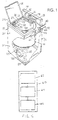
- FIG. 1 is a perspective view of an automatic washer in which the present invention could be utilized.
- FIG. 2 is a graphic illustration of rotational vessel speed.
- FIG. 3 is a graphic illustration of motor current required to rotate the vessel.
- FIG. 4 is a schematic illustration of an approach to determine bump energy between the rotating vessel and cabinet.
- FIG. 5 is a schematic illustration of an appliance embodying the present invention.
- the present invention relates to a method and apparatus for determining an out of balance condition in a rotating vessel and has applicability in a wide variety of devices in which materials are placed into a rotatable vessel, which materials may be subject to an unbalanced distribution within the vessel.
- an automatic clothes washer has been identified as an appliance within which the invention can be utilized. It should be understood that the invention can be utilized not only in a vertical axis washer as illustrated, but also horizontal or tilted axis washers, clothes dryers, centrifugal extractors and separators, and other appliances and devices in which a rotatable vessel carries a material therein, which material is subject to being arranged in an unbalanced condition.
- FIG. 1 there is illustrated at 20 generally a washing machine of the automatic type, i.e., a machine having a pre-settable sequential control apparatus for operating a washer through a pre-selected program of automatic washing, rinsing and drying operations in which the present invention may be embodied.
- Machine 20 includes a frame 22 carrying vertical panels 24 forming the sides 24a, top 24b, front 24c and back 24d of the cabinet 25 for the washing machine 20.
- a hinged lid 26 is provided in the usual manner to provide access to the interior or treatment zone 27 of the washing machine 20.
- the washing machine 20 has a console 28 including a timer dial 30 or other timing mechanism and a temperature selector 32 as well as a cycle selector 33 and other selectors as desired.
- the spin basket 36 defines a wash chamber and includes an inside wall surface extending upwardly from a substantially flat bottom.
- a motor 100 is operatively connected to the basket 36 through a transmission to rotate the basket 36 relative to the stationary tub 34.
- All of the components inside the cabinet 25 are supported by struts 39 and there may also be provided various passive elements such as shock absorbers or springs to absorb vibrations and movements of the basket and tub relative to the frame and cabinet of the washing machine 20.
- the basket 36 comprises a vessel into which materials such as a fabric load may be charged.
- the wash basket 36 is rotated at relatively high speeds in order to extract water or other wash liquids from the clothes load. If the clothes load is not evenly distributed within the wash basket, an unbalance condition occurs which will cause the rotating basket to oscillate around the axis of rotation. Hence, there will be some movement of the basket in a direction perpendicular to the axis of rotation. Depending upon the degree of unbalance and the speed of rotation, the oscillation may be small or it may be large enough to actually cause the basket 36 (and tub) 34 to engage the washer cabinet 25 or some other relatively stationary component of the appliance with some level of force. Continued operation in such a mode could cause severe damage to the washer and could cause the entire appliance to move from its otherwise stationary location, which could cause other damage or possibly hazardous conditions in the proximity of the appliance.
- stator currents are estimated by directly measuring the dc-bus current of the inverter.
- the present invention provides a method and apparatus for predicting an unbalance condition in a rotatable vessel prior to a severe unbalance condition occurring.
- FIG. 2 illustrates graphically a spin profile showing rotational speed over time.
- a rapid acceleration phase is shown at 50 which represents a rapid rise in rotational speed from a relatively low speed, such as 60 rpm, to a somewhat higher speed, such as 150 rpm.
- the speeds are more gradually ramped up to higher and higher levels such as 300 rpm, 500 rpm and 800 rpm as a final rotational speed.
- FIG. 3 illustrates measured motor current during the rapid acceleration mode and shortly thereafter.
- the actual motor current is illustrated at 52 and comprises a relatively high frequency curve.
- a bump frequency forms a component of the motor current.
- the bump frequency appears as a lower frequency represented by a running average of the motor current and is shown at 54 in a heavier line.
- the faster motor frequency can be digitally filtered out with a running average algorithm to leave the running average or bump frequency.
- FIG. 4 illustrates a comparison of the bump frequency curve with a reference curve which represents the average motor current in a balanced load.
- the areas enclosed by the bumps in the bump frequency curve represent the amount of energy with which the tub has hit the washer cabinet. This area can be calculated using standard integration techniques and the bump energy can be accumulated for a fixed amount of time, for example, about four seconds, and can then be compared to a threshold energy level in order to determine whether the spin cycle should proceed toward a higher speed or whether an out of balance signal should be generated by the control.
- the precise initial speed rate of acceleration and speed after acceleration may be varied, depending on the particular appliance involved, the size or mass of the typical load of material that the vessel is charged with, the severity of unbalance that may be expected, typical final rotational speeds for the vessel, and other parameters known to those skilled in the art. What is important is that the initial rotational speed, acceleration rate, and rotational speed after acceleration be chosen so that the speeds are not so high as to cause damage to the appliance or damage to the user if an unbalance condition exists. Also, an acceleration rate should be chosen that is sufficiently rapid so as to excite the mechanical system of the appliance to show the effects of an unbalance condition. This showing could occur such as by causing the rotating vessel, or some movable component moved by the vessel to engage a relatively stationary component of the appliance so that the energy of the engagement can be measured and compared against a predetermined value.
- the ultimate spin speed can be adaptively dropped down by the control to a safe level, in which the machine vibrations and mechanical stresses are tolerable.
- the spin speed would not initially proceed to the predetermined ultimate spin speed.
- the controller can continuously monitor the system energy dissipation so that, as water gets extracted from the clothes and the load gets lighter, the spin speed can gradually be increased up to the maximum desired value.
- the unbalance signal can immediately terminate further operation of the appliance or device until the load is redistributed.
- the present invention provides an apparatus as shown schematically in FIG. 5 in which there is an appliance 60 which comprises a vessel 62 mounted for rotation about an axis and configured to receive a supply of material and arranged relative to a relatively stationary part of the appliance 60 whereby the vessel 62 will engage the relatively stationary part in a severe unbalance loading condition of the material in the vessel while the vessel is rotating.
- an appliance 60 which comprises a vessel 62 mounted for rotation about an axis and configured to receive a supply of material and arranged relative to a relatively stationary part of the appliance 60 whereby the vessel 62 will engage the relatively stationary part in a severe unbalance loading condition of the material in the vessel while the vessel is rotating.
- the vessel is caused to rotate by a motor 64 which is operatively connected to the vessel to rotate the vessel.
- a control 66 is operably connected to the motor 64 and is arranged and configured to rapidly accelerate a rotation of the vessel through operation of the motor.
- the control is also configured to determine an amount of energy with which the vessel engages the relatively stationary part of the appliance, preferably as reflected by a characteristic of electrical current drawn by the motor.
- the control is also configured to compare the amount of energy with a predetermined value and to send a signal indicative of an unbalance condition if the amount of energy exceeds the predetermined value.
- the signal can be used to modify or control a future operation of the machine such as by effecting a redistribution mode, terminating operation of the motor and/or generating a visible or audible signal for a user of the appliance.
Landscapes
- Engineering & Computer Science (AREA)
- Textile Engineering (AREA)
- Control Of Washing Machine And Dryer (AREA)
- Testing Of Balance (AREA)
- Control Of Electric Motors In General (AREA)
- Crushing And Grinding (AREA)
Abstract
Description
Claims (20)
- In an appliance with a relatively stationary component and a rotatable vessel for holding a supply of material, a method comprising:charging said vessel with said supply of material;rotating said vessel about an axis;rapidly accelerating said rotation of said vessel;determining an amount of energy with which said vessel has engaged said relatively stationary part following a start of said rapid acceleration;comparing said amount of energy with a predetermined value; andsending a signal indicative of an unbalance condition if said amount of energy exceeds said predetermined value
- The method of claim 1, wherein said appliance is an automatic washing machine.
- The method of claim 2, wherein said washing machine is a vertical axis washer.
- The method of claim 2, wherein said washing machine is a horizontal axis washer.
- The method of claim 1, wherein said appliance is a clothes treating appliance and said material comprises a fabric load.
- The method of claim 1, wherein said relatively stationary component comprises a cabinet of said appliance.
- The method of claim 1, wherein said step of determining an amount of energy comprises rotating said vessel with an electric motor, measuring a current supplied to said motor, isolating a frequency of said current relating to said engagement of said vessel with said relatively stationary part and generating a curve representing said frequency, comparing said frequency with a curve representing a reference motor current, integrating areas above said reference curve within said engagement curve, and accumulating said areas for a predetermined time.
- The method of claim 7, wherein said step of comparing comprises comparing said accumulated area value with a predetermined threshold value.
- An appliance comprising:a vessel mounted for rotation about an axis, configured to receive a supply of material and arranged relative to a relatively stationary part of said appliance whereby said vessel will engage said relatively stationary part in a severe unbalance loading condition of said material in said vessel while said vessel is rotating;a control arranged and configured to rapidly accelerate a rotation of said vessel, determine an amount of energy with which said vessel has engaged said relatively stationary part, compare said amount of energy with a predetermined value, and send a signal indicative of an unbalance condition if said amount of energy exceeds said predetermined value.
- An appliance according to claim 9, wherein said appliance is an automatic washing machine.
- An appliance according to claim 10, wherein said washing machine is a vertical axis washer.
- An appliance according to claim 10, wherein said washing machine is a horizontal axis washer.
- An appliance according to claim 9, wherein said appliance is a clothes treating appliance and said material comprises a fabric load.
- An appliance according to claim 9, wherein said relatively stationary component comprises a cabinet, of said appliance.
- An appliance according to claim 9, including an electric motor drivingly connected to said rotatable vessel.
- An appliance according to claim 15, wherein said electric motor comprises a controlled induction motor and an inverter is provided in the control connected to the motor, said control further comprising a current measuring device connected to a dc bus of said inverter.
- An appliance according to claim 16, wherein said current measuring device provides an output signal representative of the current used by said motor, said control further including a digital filter connected to receive said output signal, said digital filter including a running average algorithm and providing an output representative of an average current used by said motor.
- An appliance according to claim 9, wherein said signal comprises one of an audible and visible signal to a user.
- An appliance according to claim 9, wherein said signal comprises an electrical signal transmitted to a further part of said control.
- An appliance having a rotatable vessel configured to receive a supply of material mounted within a relatively stationary housing, said vessel rotatable about an axis and said vessel being mounted in a fashion such that it is movable relative to said housing in a direction perpendicular to said axis, comprising:an electrical motor drivingly connected to said rotatable vessel,a control operatively connected to said motor and configured to rapidly accelerate a rotation of said vessel through operation of said motor, determine an amount of energy with which said vessel has engaged said relatively stationary part as reflected by a characteristic of electrical current drawn by said motor, compare said amount of energy with a predetermined value, and send a signal indicative of an unbalance condition if said amount of energy exceeds said predetermined value.
Applications Claiming Priority (2)
| Application Number | Priority Date | Filing Date | Title |
|---|---|---|---|
| US21420900P | 2000-06-26 | 2000-06-26 | |
| US214209P | 2000-06-26 |
Publications (3)
| Publication Number | Publication Date |
|---|---|
| EP1167610A2 true EP1167610A2 (en) | 2002-01-02 |
| EP1167610A3 EP1167610A3 (en) | 2003-08-06 |
| EP1167610B1 EP1167610B1 (en) | 2005-09-14 |
Family
ID=22798215
Family Applications (1)
| Application Number | Title | Priority Date | Filing Date |
|---|---|---|---|
| EP01115278A Expired - Lifetime EP1167610B1 (en) | 2000-06-26 | 2001-06-25 | Load unbalance prediction method and apparatus in an appliance |
Country Status (5)
| Country | Link |
|---|---|
| US (1) | US6715175B2 (en) |
| EP (1) | EP1167610B1 (en) |
| CN (1) | CN1331411A (en) |
| BR (1) | BR0102578B1 (en) |
| DE (1) | DE60113335T2 (en) |
Cited By (3)
| Publication number | Priority date | Publication date | Assignee | Title |
|---|---|---|---|---|
| WO2004097099A1 (en) * | 2003-04-28 | 2004-11-11 | Emerson Electric Co. | Method and system for determining a washing machine load unbalance |
| EP1548169A4 (en) * | 2002-07-22 | 2006-08-16 | Toshiba Kk | Drum washing machine |
| WO2006124535A1 (en) * | 2005-05-12 | 2006-11-23 | Emerson Electric Co. | Method and system for operating a clothes washing machine |
Families Citing this family (36)
| Publication number | Priority date | Publication date | Assignee | Title |
|---|---|---|---|---|
| IT1310142B1 (en) * | 1999-08-20 | 2002-02-11 | Merloni Elettrodomestici Spa | DEVICE, SYSTEM AND METHOD FOR THE MONITORING OF A DOMESTIC ELECTRICITY USE, IN PARTICULAR A HOUSEHOLD APPLIANCE. |
| DE10234053C1 (en) * | 2002-07-26 | 2003-11-20 | Diehl Ako Stiftung Gmbh & Co | Imbalance detection method for washing machine drum using variations in power requirement of drive motor providing drum rotation |
| JP2004130059A (en) * | 2002-10-10 | 2004-04-30 | Lg Electronics Inc | Dehydration operation control method for drum washing machine |
| DE10305675B3 (en) * | 2003-02-12 | 2004-05-27 | Diehl Ako Stiftung & Co. Kg | Drum loading determination method for laundry machine using measured electrical power requirements of electric drive motor for loaded laundry drum |
| US7471054B2 (en) * | 2003-06-11 | 2008-12-30 | Askoll Holding S.R.L. | Method for detecting unbalanced conditions of a rotating load driven by a synchronous motor and for controlling said motor |
| US7627960B2 (en) * | 2003-06-30 | 2009-12-08 | General Electric Company | Clothes dryer drum projections |
| US7216049B2 (en) * | 2004-06-23 | 2007-05-08 | Whirlpool Corporation | Method for calibrating current offset and filtering bad data in a system that detects power output |
| EP1696070B1 (en) | 2005-02-25 | 2010-10-20 | Askoll Holding S.r.l. | Washing machine or similar household appliance activated by a synchronous electric motor with a detecting device of unbalance conditions |
| US8042211B2 (en) * | 2005-08-16 | 2011-10-25 | Whirlpool Corporation | Method of detecting an off-balance condition of a clothes load in a washing machine |
| US7739765B2 (en) * | 2006-11-09 | 2010-06-22 | Whirlpool Corporation | Tangling detection for an automatic washer |
| US20080120789A1 (en) * | 2006-11-29 | 2008-05-29 | Farhad Ashrafzadeh | Cloth bunching detection and adjustment for an automatic washer |
| US20080156094A1 (en) * | 2006-12-27 | 2008-07-03 | General Electric Company | Systems and methods for detecting out-of-balance conditions in electronically controlled motors |
| KR101287536B1 (en) * | 2007-06-05 | 2013-07-18 | 삼성전자주식회사 | Washing machine and its control method |
| US20090107185A1 (en) * | 2007-10-24 | 2009-04-30 | Mariano Filippa | Method and apparatus for determining an imbalance condition in an appliance |
| WO2010071458A1 (en) | 2008-12-17 | 2010-06-24 | Fisher & Paykel Appliances Limited | A laundry machine |
| DE102008055092A1 (en) * | 2008-12-22 | 2010-06-24 | BSH Bosch und Siemens Hausgeräte GmbH | Method for predicting an imbalance, corresponding device and household appliance with such a device |
| KR101588202B1 (en) * | 2009-01-09 | 2016-01-25 | 엘지전자 주식회사 | Method for washing and Washing machine |
| DE102009028810A1 (en) * | 2009-08-21 | 2011-02-24 | BSH Bosch und Siemens Hausgeräte GmbH | Method for determining an imbalance in a laundry drum of a washing machine in the spin mode, drive device and washing machine with a drive device |
| US8499392B2 (en) * | 2010-01-29 | 2013-08-06 | General Electric Company | Apparatus and method for detecting unbalanced loads in a washing machine |
| CN102959153B (en) | 2010-06-24 | 2015-10-14 | 尼得科电机有限公司 | The unbalanced detection of washing machine |
| FR2971136B1 (en) * | 2011-02-03 | 2013-02-08 | Seb Sa | CULINARY PREPARATION APPARATUS COMPRISING A BALOURD DETECTION |
| US9115456B2 (en) * | 2011-12-20 | 2015-08-25 | Whirlpool Corporation | Method for detecting satellization speed of clothes load in a horizontal axis laundry treating appliance |
| US8813288B2 (en) | 2012-01-25 | 2014-08-26 | General Electric Company | System and method for detecting imbalance in a washing machine |
| US9518350B2 (en) | 2013-01-08 | 2016-12-13 | Whirlpool Corporation | Method, system, and device for adjusting operation of washing machine based on system modeling |
| US9145634B2 (en) * | 2013-06-04 | 2015-09-29 | Whirlpool Corporation | Method of operating a laundry treating appliance |
| US20150052687A1 (en) * | 2013-08-20 | 2015-02-26 | General Electric Company | Method for operating a washing machine appliance |
| US9518351B2 (en) | 2013-11-13 | 2016-12-13 | Haier Us Appliance Solutions, Inc. | Washing machine appliance |
| BR112018001925B1 (en) * | 2015-07-31 | 2021-11-23 | Guangdong Welling Motor Manufacturing Co., Ltd. | UNBALANCE DETECTION METHOD, UNBALANCE DETECTION DEVICE, AND FRONT LOAD WASHING MACHINE |
| CN104963164B (en) * | 2015-07-31 | 2017-05-10 | 广东威灵电机制造有限公司 | Roller washing machine and control method and device thereof |
| CN105862313A (en) * | 2016-04-29 | 2016-08-17 | 无锡小天鹅股份有限公司 | Eccentricity sensing method for pulsator washing machine and pulsator washing machine |
| US10060067B2 (en) * | 2016-05-10 | 2018-08-28 | Haier Us Appliance Solutions, Inc. | Determining out of balance conditions of a washing machine |
| US10619284B2 (en) | 2017-05-26 | 2020-04-14 | Whirlpool Corporation | Laundry treating appliance and method of operation |
| US11021825B2 (en) * | 2018-04-11 | 2021-06-01 | Haier Us Appliance Solutions, Inc. | Washing machine appliance with location detection of imbalanced loads |
| KR20210020549A (en) * | 2019-08-16 | 2021-02-24 | 엘지전자 주식회사 | Laundry processing apparatus and control method thereof |
| US11959215B2 (en) | 2021-04-22 | 2024-04-16 | Electrolux Home Products, Inc. | Wash article entrapment detection for laundry washing machines |
| US11725323B2 (en) | 2021-04-22 | 2023-08-15 | Electrolux Home Products, Inc. | Wash article entrapment detection for laundry washing machines |
Family Cites Families (14)
| Publication number | Priority date | Publication date | Assignee | Title |
|---|---|---|---|---|
| GB2102985A (en) | 1981-07-31 | 1983-02-09 | Philips Electronic Associated | Drum speed control system for a washing machine |
| GB2174513B (en) * | 1985-05-03 | 1988-11-09 | Hoover Plc | Spin speed control means for laundry spin driers or other centrifuges |
| US4765161A (en) | 1987-10-19 | 1988-08-23 | American Laundry Machinery, Inc. | Out-of-balance control for laundry machines |
| DE3812371A1 (en) * | 1988-04-14 | 1989-10-26 | Licentia Gmbh | Method for measuring the distribution of washing, especially in washing machines |
| US5070565A (en) | 1989-04-17 | 1991-12-10 | Emerson Electric Co. | Unbalanced load detection system and method for a household appliance |
| JPH08122192A (en) * | 1994-10-21 | 1996-05-17 | Mitsubishi Electric Corp | Induction motor load state detection device and method |
| IT1271782B (en) * | 1994-12-21 | 1997-06-09 | Whirlpool Italia | METHOD AND ARRANGEMENT TO OBTAIN A BALANCE OF THE LOAD IN THE WASHING MACHINE MACHINES |
| KR20000007275A (en) | 1998-07-02 | 2000-02-07 | 윤종용 | Method for detecting unbalance of drum washing machine |
| US6282965B1 (en) * | 1998-11-20 | 2001-09-04 | Emerson Electric Co. | Method and apparatus for detecting washing machine tub imbalance |
| US6381791B1 (en) * | 1998-11-20 | 2002-05-07 | Emerson Electric Co. | Washing machine tub speed control method and apparatus |
| US6442979B1 (en) * | 1999-05-06 | 2002-09-03 | Emerson Electric Co. | Washing machine motor control device and method |
| US6418581B1 (en) * | 1999-06-24 | 2002-07-16 | Ipso-Usa, Inc. | Control system for measuring load imbalance and optimizing spin speed in a laundry washing machine |
| US6578225B2 (en) * | 2000-05-25 | 2003-06-17 | Skf Autobalance Systems Ab | Low-speed prebalancing for washing machines |
| US6594841B2 (en) * | 2001-09-21 | 2003-07-22 | Maytag Corporation | Unbalance detection system for a washing machine |
-
2001
- 2001-06-20 US US09/885,842 patent/US6715175B2/en not_active Expired - Lifetime
- 2001-06-25 EP EP01115278A patent/EP1167610B1/en not_active Expired - Lifetime
- 2001-06-25 CN CN01124324A patent/CN1331411A/en active Pending
- 2001-06-25 DE DE60113335T patent/DE60113335T2/en not_active Expired - Lifetime
- 2001-06-26 BR BRPI0102578-3A patent/BR0102578B1/en not_active IP Right Cessation
Cited By (5)
| Publication number | Priority date | Publication date | Assignee | Title |
|---|---|---|---|---|
| EP1548169A4 (en) * | 2002-07-22 | 2006-08-16 | Toshiba Kk | Drum washing machine |
| WO2004097099A1 (en) * | 2003-04-28 | 2004-11-11 | Emerson Electric Co. | Method and system for determining a washing machine load unbalance |
| US7591038B2 (en) | 2003-04-28 | 2009-09-22 | Emerson Electric Co., | Method and system for operating a clothes washing machine |
| US7905122B2 (en) | 2003-04-28 | 2011-03-15 | Nidec Motor Corporation | Method and system for determining a washing machine load unbalance |
| WO2006124535A1 (en) * | 2005-05-12 | 2006-11-23 | Emerson Electric Co. | Method and system for operating a clothes washing machine |
Also Published As
| Publication number | Publication date |
|---|---|
| BR0102578B1 (en) | 2009-01-13 |
| BR0102578A (en) | 2002-02-05 |
| US20020035757A1 (en) | 2002-03-28 |
| US6715175B2 (en) | 2004-04-06 |
| EP1167610A3 (en) | 2003-08-06 |
| EP1167610B1 (en) | 2005-09-14 |
| CN1331411A (en) | 2002-01-16 |
| DE60113335T2 (en) | 2006-03-23 |
| DE60113335D1 (en) | 2005-10-20 |
Similar Documents
| Publication | Publication Date | Title |
|---|---|---|
| US6715175B2 (en) | Load unbalanced prediction method and apparatus in an appliance | |
| US6640372B2 (en) | Method and apparatus for detecting load unbalance in an appliance | |
| CN100453727C (en) | Washing machine and method for controlling same | |
| JP3316427B2 (en) | Centrifugal dehydrator | |
| US7530133B2 (en) | Method for controlling a spin cycle in a washing machine | |
| EP1297209B1 (en) | Low-speed prebalancing for washing machines | |
| KR101661962B1 (en) | Method for controlling process in washing machine | |
| CN104246051B (en) | Tumbling-box washing machine | |
| KR20080107097A (en) | Washing machine and control method | |
| JPH074464B2 (en) | Fully automatic washing machine | |
| KR102604224B1 (en) | Control Method of Washing Machine | |
| AU2016427897A1 (en) | Pre-drain unbalance detection in a washing machine | |
| US20130199246A1 (en) | Dynamic unbalance detection in a washing machine | |
| JP3332769B2 (en) | Centrifugal dewatering device | |
| US7039976B2 (en) | Braking control system for a washing machine | |
| RU2301856C2 (en) | Washing machine | |
| JP7252534B2 (en) | Dehydrator | |
| JP2006000387A (en) | Drum washing machine | |
| KR20210079728A (en) | Controlling Method of Laundry Treatment Apparatus | |
| JPH0910480A (en) | Centrifugal hydroextractor | |
| JPH10305189A (en) | Centrifugal dehydrator | |
| CN113167001B (en) | Rotatable drum washing machine and control method thereof | |
| JP3108350B2 (en) | Centrifugal dehydrator | |
| JP2005342274A (en) | Drum washing machine | |
| JPH09140996A (en) | Centrifugal dehydrator |
Legal Events
| Date | Code | Title | Description |
|---|---|---|---|
| PUAI | Public reference made under article 153(3) epc to a published international application that has entered the european phase |
Free format text: ORIGINAL CODE: 0009012 |
|
| AK | Designated contracting states |
Kind code of ref document: A2 Designated state(s): AT BE CH CY DE DK ES FI FR GB GR IE IT LI LU MC NL PT SE TR |
|
| AX | Request for extension of the european patent |
Free format text: AL;LT;LV;MK;RO;SI |
|
| PUAL | Search report despatched |
Free format text: ORIGINAL CODE: 0009013 |
|
| AK | Designated contracting states |
Designated state(s): AT BE CH CY DE DK ES FI FR GB GR IE IT LI LU MC NL PT SE TR |
|
| AX | Request for extension of the european patent |
Extension state: AL LT LV MK RO SI |
|
| 17P | Request for examination filed |
Effective date: 20040114 |
|
| AKX | Designation fees paid |
Designated state(s): DE FR GB IT |
|
| 17Q | First examination report despatched |
Effective date: 20040406 |
|
| GRAP | Despatch of communication of intention to grant a patent |
Free format text: ORIGINAL CODE: EPIDOSNIGR1 |
|
| GRAS | Grant fee paid |
Free format text: ORIGINAL CODE: EPIDOSNIGR3 |
|
| GRAA | (expected) grant |
Free format text: ORIGINAL CODE: 0009210 |
|
| AK | Designated contracting states |
Kind code of ref document: B1 Designated state(s): DE FR GB IT |
|
| REG | Reference to a national code |
Ref country code: GB Ref legal event code: FG4D |
|
| REF | Corresponds to: |
Ref document number: 60113335 Country of ref document: DE Date of ref document: 20051020 Kind code of ref document: P |
|
| ET | Fr: translation filed | ||
| PLBE | No opposition filed within time limit |
Free format text: ORIGINAL CODE: 0009261 |
|
| STAA | Information on the status of an ep patent application or granted ep patent |
Free format text: STATUS: NO OPPOSITION FILED WITHIN TIME LIMIT |
|
| 26N | No opposition filed |
Effective date: 20060615 |
|
| PGFP | Annual fee paid to national office [announced via postgrant information from national office to epo] |
Ref country code: GB Payment date: 20090625 Year of fee payment: 9 |
|
| GBPC | Gb: european patent ceased through non-payment of renewal fee |
Effective date: 20100625 |
|
| PG25 | Lapsed in a contracting state [announced via postgrant information from national office to epo] |
Ref country code: GB Free format text: LAPSE BECAUSE OF NON-PAYMENT OF DUE FEES Effective date: 20100625 |
|
| REG | Reference to a national code |
Ref country code: FR Ref legal event code: PLFP Year of fee payment: 16 |
|
| PGFP | Annual fee paid to national office [announced via postgrant information from national office to epo] |
Ref country code: DE Payment date: 20160622 Year of fee payment: 16 |
|
| PGFP | Annual fee paid to national office [announced via postgrant information from national office to epo] |
Ref country code: FR Payment date: 20160516 Year of fee payment: 16 |
|
| PGFP | Annual fee paid to national office [announced via postgrant information from national office to epo] |
Ref country code: IT Payment date: 20160621 Year of fee payment: 16 |
|
| REG | Reference to a national code |
Ref country code: DE Ref legal event code: R119 Ref document number: 60113335 Country of ref document: DE |
|
| REG | Reference to a national code |
Ref country code: FR Ref legal event code: ST Effective date: 20180228 |
|
| PG25 | Lapsed in a contracting state [announced via postgrant information from national office to epo] |
Ref country code: DE Free format text: LAPSE BECAUSE OF NON-PAYMENT OF DUE FEES Effective date: 20180103 |
|
| PG25 | Lapsed in a contracting state [announced via postgrant information from national office to epo] |
Ref country code: FR Free format text: LAPSE BECAUSE OF NON-PAYMENT OF DUE FEES Effective date: 20170630 Ref country code: IT Free format text: LAPSE BECAUSE OF NON-PAYMENT OF DUE FEES Effective date: 20170625 |