EP1167170A2 - A directional annular elastic track - Google Patents
A directional annular elastic track Download PDFInfo
- Publication number
- EP1167170A2 EP1167170A2 EP01112979A EP01112979A EP1167170A2 EP 1167170 A2 EP1167170 A2 EP 1167170A2 EP 01112979 A EP01112979 A EP 01112979A EP 01112979 A EP01112979 A EP 01112979A EP 1167170 A2 EP1167170 A2 EP 1167170A2
- Authority
- EP
- European Patent Office
- Prior art keywords
- track
- lugs
- groove
- lateral end
- lateral
- Prior art date
- Legal status (The legal status is an assumption and is not a legal conclusion. Google has not performed a legal analysis and makes no representation as to the accuracy of the status listed.)
- Granted
Links
- 238000010276 construction Methods 0.000 abstract description 6
- 229910000831 Steel Inorganic materials 0.000 description 8
- 239000010959 steel Substances 0.000 description 8
- 238000005452 bending Methods 0.000 description 7
- 239000002689 soil Substances 0.000 description 7
- 238000000465 moulding Methods 0.000 description 4
- 230000002093 peripheral effect Effects 0.000 description 4
- 230000009286 beneficial effect Effects 0.000 description 3
- 238000013461 design Methods 0.000 description 3
- 238000000034 method Methods 0.000 description 3
- 230000008901 benefit Effects 0.000 description 2
- 238000005188 flotation Methods 0.000 description 2
- 238000012423 maintenance Methods 0.000 description 2
- 239000000463 material Substances 0.000 description 2
- JOYRKODLDBILNP-UHFFFAOYSA-N Ethyl urethane Chemical compound CCOC(N)=O JOYRKODLDBILNP-UHFFFAOYSA-N 0.000 description 1
- 230000002411 adverse Effects 0.000 description 1
- 230000003466 anti-cipated effect Effects 0.000 description 1
- 238000013459 approach Methods 0.000 description 1
- 230000004888 barrier function Effects 0.000 description 1
- 238000003490 calendering Methods 0.000 description 1
- 230000008859 change Effects 0.000 description 1
- 238000005056 compaction Methods 0.000 description 1
- 230000000052 comparative effect Effects 0.000 description 1
- 230000007547 defect Effects 0.000 description 1
- 230000002950 deficient Effects 0.000 description 1
- 238000007599 discharging Methods 0.000 description 1
- 238000004519 manufacturing process Methods 0.000 description 1
- 238000005259 measurement Methods 0.000 description 1
- 230000007246 mechanism Effects 0.000 description 1
- 239000002184 metal Substances 0.000 description 1
- 230000008569 process Effects 0.000 description 1
- 230000002787 reinforcement Effects 0.000 description 1
- 230000003014 reinforcing effect Effects 0.000 description 1
- 239000004576 sand Substances 0.000 description 1
- 238000000926 separation method Methods 0.000 description 1
Images


Classifications
-
- B—PERFORMING OPERATIONS; TRANSPORTING
- B62—LAND VEHICLES FOR TRAVELLING OTHERWISE THAN ON RAILS
- B62D—MOTOR VEHICLES; TRAILERS
- B62D55/00—Endless track vehicles
- B62D55/08—Endless track units; Parts thereof
- B62D55/18—Tracks
- B62D55/24—Tracks of continuously flexible type, e.g. rubber belts
Definitions
- This invention relates to an annular elastic track for use in vehicles for civil engineering, construction works and agricultural works.
- Rubber tracks are in many cases being substituted for conventional metal tracks. Rubber tracks offer better maneuverability, better ride quality in rough fields, better flotation in wet areas, improved side hill stability, excellent traction, low maintenance and versatility compared to steel tracks.
- rubber tracks are replacing conventional rubber tires on tractor and other agricultural vehicles such as combines, trenchers, snow removers, spreaders, sprayers, wagons and carts, since rubber tracks are more friendly to agricultural fields, offer better flotation and less compaction than rubber tires, resulting in better crop yield.
- the use of rubber tractor tracks permits farmers to get in and out of fields earlier in the planting season and plant more crops as compared to rubber tire-equipped agricultural vehicles.
- tracks are employed on many construction equipment type vehicles such as road pavers and the like. These tracks are generally made from steel or steel with urethane or rubber pads. These tracks require much maintenance and in the case of steel tracks the damage to paved surfaces is a serious problem. Also, these construction type tracks can be placed over pneumatic tires for skid steer equipment. A new advance in this area is the use of an all rubber steel cord track.
- the Goodyear Tire & Rubber Company provides such a track under the trademark TRACKMAN®, and the Bridgestone/Firestone Company provides a similar track under the name Firetrax®.
- These tracks have rubber lugs that extend across the entire width of the track. Each has swept back axially outer portions, which limits the amount of lateral extending edges. These tracks are good on paved surfaces, but are deficient in applications that have wet soil or loose sand and gravel. Additionally, the swept back outer ends create bending stresses on the underlying belt structure as the track bends over the wheels.
- Rubber tracks are defined by an endless rubber belt reinforced with continuous flexible steel cables bonded into the rubber.
- a complete rubber track is molded flat in multiple sections, which are sequentially then bonded together during the curing process.
- an endless rubber track can be made in annular form wherein the track is made from an uncured belt and a plurality of drive lugs wherein the drive lugs are urged into cavities formed in inner segments of a molding press, partially final formed and pressed onto the inner periphery of the belt, the belts and drive lugs are positioned in the molding press to be cured and molded together while treads are formed on the outer periphery of the belt. The drive lugs are finally formed and the completed belt is cooled and removed from the molding press forming an annular track as described in US-A- 6,051,178.
- the outer periphery has a plurality of spaced tread lugs.
- these tread lugs extend from each lateral edge of the track towards the center of the track terminating at the central location or mid-point of the track.
- These lugs generally take the appearance of agricultural tire lugs with a generally inclined but slightly more transverse extending inclination relative to the direction of travel. Lugs of this design have inherently experienced high wear patterns in the central location of the track. Additionally, these lugs have been staggered or are circumferentially off-set from one side of the track to the other.
- a directional annular elastic track has guide lugs on the inner circumference and rubber tread lugs on the outer circumference and a thin band continuously extending in the circumferential direction.
- the thin band is circumferentially reinforced by substantially inextensible cords or bands.
- the cords or bands are steel reinforced materials.
- the track has a plurality of spaced rubber tread lugs.
- Each rubber tread lug has a first lateral end portion, a middle portion and a second lateral end portion. Each portion is oriented perpendicular to the circumferential direction wherein the middle portion is projected forward relative to the lateral portions.
- Each rubber tread lug is separated by a groove.
- the groove extends completely across the track and has a groove width (W M ) between the middle portions of adjacent lugs and a groove width (W L ) between the first and second lateral end portions of adjacent lugs.
- the groove width (W M ) is less than (W L ).
- the groove width (W M ) is 75% or less than the lateral groove width (W L ).
- the plane (P L ) intersects at most one groove wall in each of the lateral end portions of the tread lugs.
- the lugs have a radially outer tread surface located between a leading edge and a trailing edge.
- the leading edge and trailing edge are parallel over a majority of the lug length and in the middle portion protrudes toward the forward direction of travel of the track.
- the leading edge adjacent the middle portion extends at an amplitude (A L ) from the leading edge adjacent the lateral ends.
- the trailing edge adjacent the middle portion extends at an amplitude (A T ) relative to the trailing edges adjacent the lateral end portions.
- (A L ) is 125% or more than (A T ) as measured relative to the corresponding edges of the lateral end portions.
- each of the lateral end portions is circumferentially aligned relative to the tracks direction of travel.
- each lug lateral end portion has an outer chamfered lug wall extending in the circumferential direction.
- FIG. 1 there is shown a completed rubber track made according to the prior art.
- This track has a plurality of lugs 30 extending from each side of the lateral edges of the track towards the middle of the track. These lugs are designed somewhat similar to the lugs found on tractor tires.
- Such a track of the prior art comprises an endless band 20 formed of rubber calendered to encapsulate cord and wire cable. It will be understood that such a track is adapted to be positioned upon the wheels or rollers (not shown) of a motorized vehicle such as a tractor or the like to support the vehicle from movement along a desired surface such as an agricultural field.
- the exterior peripheral surface of band 20 is formed with integral tread lugs 30.
- the center portion of the inner peripheral surface of band 20 is formed with a plurality of conventional drive or guide lugs 32 which can engage complimentary sprockets (not shown) on the wheels or rollers of the drive vehicle which is supported by the track.
- a plurality of conventional drive or guide lugs 32 which can engage complimentary sprockets (not shown) on the wheels or rollers of the drive vehicle which is supported by the track.
- Figure 2 shows a perspective view of the track 10 wherein the tread lugs 30 extend across the entire outer peripheral surface of the track.
- the band 20 has a plurality of metallic or steel cables for reinforcement shown as 59 and 58 in the drawing encapsulated in rubber 22.
- the drive lugs 32 are shown in the central portion of the track 10 on its inner peripheral surface 31.
- the tread lugs 30 extend outward from the tread band 20 to an outer surface 33.
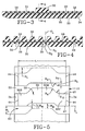
- Each tread lug 30 has a leading edge 40 and a trailing edge 42 as illustrated in Fig 5 of the drawings. The distance between the leading edges 40 and the trailing edges 42 defines the lug width.
- Each lug has a chamfered lateral sidewall 34 extending outwardly to a lateral edge 44, in each of the lateral end portions of the tread lug 30B, 30C.
- the middle portion of each lug is designated 30M.
- Each lateral end portion 30B and 30C is circumferentially aligned as illustrated in the preferred tread pattern and the lateral end portions are equal in width. As illustrated in the preferred embodiment, the middle portion 30M projects forward relative to the lateral end portions 30B, 30C.
- Each rubber tread lug 30 is separated by a groove 60, the groove 60 extends completely across the track and has a groove width (W M ) between middle portions 30M of adjacent lugs and a groove width (W L ) between the first and second lateral end portions of adjacent lugs 30.
- the groove width (W M ) is less than the groove width (W L ).
- the groove width (W M ) is preferably 75% or less than the lateral groove width (W L ) more preferably about 50% of the groove width (W L ).
- the base of the groove 60 is defined by a full radius of curvature (R 1 ) in the preferred embodiment.
- R 1 a full radius of curvature
- the groove In the area adjacent the middle portion 30M of the tread lug. At the lateral extremes of the middle portion near their lateral end portions 30B and 30C, the groove has a radius of curvature at the base of (R 2 ). wherein (R 2 ) is approximately two times the dimension of the radius (R 1 ).
- the groove walls adjacent the trailing edge 42 at least in the lateral edge portions have a slope approaching vertical.
- all the groove walls had an inclination of approximately 20° as they extended towards the tread base. While this uniform bracing of the lugs is considered typical and facilitates molding, it is none-the-less believed advantageous in some cases to have the trailing edges in the lateral portions 30B and 30C vertical or having a close to zero degree taper to facilitate the bending of the track as it rolls around the drive wheels.
- the lugs 30 have the radially outer tread surface 33 located between a leading edge 40 and a trailing edge 42.
- the leading edges 40 and trailing edges 42 are parallel over a majority the lugs length and in the middle portion the leading edge 40 protrudes towards the forward direction of travel. In a preferred embodiment illustrated in Figure 5, both the leading edge 40 and the trailing edge 42 protrude toward the forward direction of the travel of the track..
- the leading edge 40 adjacent the middle portion 30M extends at an amplitude (A L ) from the leading edge 40 adjacent the lateral end portions 30B or 30C.
- the trailing edge 42 adjacent the middle portion extends an amplitude (A T ) relative to the trailing edge 42 adjacent the lateral end portions 30B or 30C.
- the amplitude A T ranges from 0 to one-half the groove width at the middle portion (one-half W M ). It is believed preferable that the amplitude A L should be 125% or more than the amplitude A T as measured relative to the corresponding edges 40,42 of the lateral end portions 30A, 30B.
- each lug lateral end portion 30B, 30C has an outer chamfered lug wall 34 extending in the circumferential direction as illustrated in Figure 5.
- the chamfered lug wall 34 extends to a generally vertical outer wall 37 that connects to the underlying band 20 of the track.
- the groove 60 forms an effective soil discharge channel extending from the center of the track outwardly over the lateral edges of the track.
- the groove 60 opens up to a wider groove width (W L ) as the tread approaches the lateral edge.
- W L groove width
- the opening of the groove 60 in this area facilitates the removal of soil and mud as the track 10 revolves around the drive wheels.
- the central portion wherein the drive wheels engage the guide lugs is an area where the track is subjected to generally high wear.
- the unique shape of the tread lugs 30 insure that the middle portion 30M has an enlarged surface area that is anywhere from 125% to 150% greater in the circumferential direction than the lateral edge portions. This increases the treadwear characteristics in this critical area.
- the leading edge and trailing edges are contoured with a radius R 4 and R 5 respectively as illustrated in Figure 5.
- the leading edge 40 as it projects forward on the track creates an area that increases the lateral maneuverability of the track and provides some lateral resistance to slippage as the vehicle is traversing. This is particularly important when a track vehicle is working on a slope terrain or a contoured terrain where the vehicle is at a slight tilt. It is very important under these conditions that the track vehicle has some edges that will prevent the track from slipping. It is best accomplished at the lateral extremes along the walls 34 and 35, but additionally this track has the leading edge 40 projecting outward at the middle portion creating additional surfaces to resist lateral slipping. Effectively this creates a barrier to slippage almost down the entire length of the track and gives the track footprint much more resistance to any lateral slippage.
- This feature not only increases the ability to resist lateral slippage, but further enhances maneuverability in quick turning movements as it provides additional edges to facilitate the turning.
- a pivot point is actually created that helps provide a good wear surface for pivoting on this location and each of the tread lugs. Applicants have found this extremely beneficial in turning maneuvers of a track vehicle.
- a second beneficial feature of the track of the present invention over that of the prior art track is that the use of single lugs extending clear across the track width means that more lug edges are available for forward propulsion of the track vehicle. This is true because circumferentially offsetting lugs that are positioned only halfway across the track means that fewer lugs can be located on the track in order to insure sufficient spacing as illustrated in the prior art track of Figure 1. Looking at Figure 2 of the present invention these fully extending lugs 30 have an increase wear surface area in the middle, but also provide increased laterally extending edges and groove walls for forward and rearward propulsion of the track vehicle because the lugs can be more closely spaced while still providing sufficient soil discharge channels. This means that a larger surface area of the track is occupied by tread lugs.
- the track will wear at a far superior rate than the conventional prior art track, but additionally will have greater forward and rearward traction. It is anticipated based on just the surface area measurements that at least 50% more surface area is provided in the track of the present invention then that of the track illustrated in the prior art Figure 1. This, in combination with the unique structure of the lugs, means that the track of the present invention should be at least 50% and likely to be almost 100% more durable in terms of treadwear then the prior art track. For the farmer, this means the track of the present invention should have a useful life twice as long as the track of the prior art when using similar comparative materials. In construction applications the inventive track will provide superior wear rates, as well, with better wet area traction capability, while protecting the pneumatic tires, if used with the track from puncture damage.
- a second very beneficial feature of the present invention is that many tracks vary in length and in track width from approximately 12 to 15 inches in track width upwards to 36 inches in track width.
- the length of the track can change from a few feet spacing between the ecliptic ends to upwards of 20 feet or more in the larger track sizes.
- the lug pattern of the present invention is such that a mold can be made with center inserts that would allow the middle portion 30M of the lugs to be expanded outwardly while leaving the lateral edge portions the same.
- the tread of Figure 5 imagine placing an insert having the central portion only expanded by placing an insert in the platen that forms this section of the track.
- each lateral portion 30B,30C can be expanded by placing an insert in the lateral region thereby expanding the width of the lateral portions.
- each portion 30B,30C and 30M can be inserted to increase the track width while expanding the lugs 30 proportionally lengthwise.
Landscapes
- Engineering & Computer Science (AREA)
- Chemical & Material Sciences (AREA)
- Combustion & Propulsion (AREA)
- Transportation (AREA)
- Mechanical Engineering (AREA)
- Tires In General (AREA)
- Pretreatment Of Seeds And Plants (AREA)
Abstract
Description
Claims (8)
- A directional elastic track (10) having guide lugs (32) on the inner circumference (31) and rubber tread lugs (30) on the outer circumference and a thin band (20) continuously extending in the circumferential direction, the thin band being circumferentially reinforced by substantially inextensible cords or bands (58,59), the track comprising:
a plurality of spaced rubber tread lugs each having a first lateral end portion (30B), a middle portion (30M) and a second lateral end portion (30C), characterized by each portion being oriented perpendicular to the circumferential direction wherein the middle portion (30M) is projected forward relative to the lateral end portions (30B,30C). - The directional annular elastic track of claim 1 wherein each rubber tread lug (30) is separated by a groove (60), the groove extending completely across the track and having a groove width (WM) between the middle portions (30M) adjacent lugs (30) and a groove width WL between the first and second lateral ends portions (30B,30C) of adjacent lugs, the groove width (WM) being less than (WL).
- The directional annular elastic track of claim 2 wherein the middle groove width (WM) is 75.0% or less than the lateral groove with(WL).
- The directional annular elastic track of claim 2 wherein a plane (PL) extending perpendicular to the track circumferential length lies within each groove (60) and is centered in the groove between adjacent middle portions (30M), the plane (PL) intersecting at most one groove wall in each of the lateral end portions (30B,30C) of the tread lugs.
- The directional annular elastic track of claim 2 wherein the lugs (30) have a radially outer tread surface (33) located between a leading edge (40) and a trailing edge (42), the leading edge and trailing edges being parallel over a majority of the lug length (L) and in the middle portion (30M) at least the leading edge protrudes toward the forward direction of travel of the track.
- The directional annular elastic track of claim 5 wherein the leading edge (40) adjacent the middle portion (30M) extends at an amplitude (AL) from the leading edge adjacent the lateral end (30B,30C) and the trailing edge (42) adjacent the middle portion (30M) extends at an amplitude (AT, AL) being 125% or more than (AT) as measured relative to the corresponding edges of the lateral end portions.
- The directional annular elastic track of claim 1 wherein the lugs (30) have a total lug length (L) the middle portion being at least 50% of (L) in length.
- The directional annular elastic track of claim 1 wherein each lug lateral end portion (30B,30C) has an outer chamfered lug wall (34) extending in the circumferential direction.
Applications Claiming Priority (2)
| Application Number | Priority Date | Filing Date | Title |
|---|---|---|---|
| US09/596,592 US6352320B1 (en) | 2000-06-19 | 2000-06-19 | Directional annular elastic track |
| US596592 | 2000-06-19 |
Publications (3)
| Publication Number | Publication Date |
|---|---|
| EP1167170A2 true EP1167170A2 (en) | 2002-01-02 |
| EP1167170A3 EP1167170A3 (en) | 2005-08-10 |
| EP1167170B1 EP1167170B1 (en) | 2007-01-03 |
Family
ID=24387912
Family Applications (1)
| Application Number | Title | Priority Date | Filing Date |
|---|---|---|---|
| EP01112979A Expired - Lifetime EP1167170B1 (en) | 2000-06-19 | 2001-06-08 | A directional annular elastic track |
Country Status (5)
| Country | Link |
|---|---|
| US (1) | US6352320B1 (en) |
| EP (1) | EP1167170B1 (en) |
| JP (1) | JP2002046668A (en) |
| BR (1) | BR0102345A (en) |
| DE (1) | DE60125642T2 (en) |
Cited By (1)
| Publication number | Priority date | Publication date | Assignee | Title |
|---|---|---|---|---|
| CN101605690B (en) * | 2007-02-05 | 2013-04-17 | 株式会社普利司通 | Rubber crawler track |
Families Citing this family (22)
| Publication number | Priority date | Publication date | Assignee | Title |
|---|---|---|---|---|
| CA2390209A1 (en) * | 2001-08-10 | 2003-02-10 | The Goodyear Tire & Rubber Company | Endless two part rubber track comprised of polyurethane based tread component and rubber carcass component and vehicle containing such track |
| US7121636B2 (en) * | 2001-09-04 | 2006-10-17 | Ingersoll-Rand Company | Endless track for paving vehicles |
| CA2455279A1 (en) * | 2004-01-16 | 2005-07-16 | Camoplast Inc. (Power Sports) | Manoeuvrable traction track |
| US7234495B2 (en) * | 2004-12-15 | 2007-06-26 | The Goodyear Tire & Rubber Company | Underground mine tire |
| US20070075456A1 (en) * | 2005-10-05 | 2007-04-05 | Feldmann Thomas B | Method to cure endless track belts |
| US20070075583A1 (en) * | 2005-10-05 | 2007-04-05 | Feldmann Thomas B | Apparatus to cure endless track belts |
| US20090101042A1 (en) * | 2006-08-30 | 2009-04-23 | Glyde-Rail Licensing, Llc | Apparatus for enabling an excavator to mount, demount and travel on railroad tracks |
| US20080053332A1 (en) * | 2006-08-30 | 2008-03-06 | John Roy | Apparatus for enabling an excavator to mount, demount and travel on railroad tracks |
| DE602008005816D1 (en) * | 2007-09-13 | 2011-05-12 | Cnh Italia Spa | Chain body for tracked vehicles |
| EP2096021B1 (en) * | 2008-02-27 | 2010-06-02 | Solideal Holding Sa | Rubber crawler, method for making rubber crawler and vehicle provided with rubber crawler |
| KR101146092B1 (en) | 2009-12-11 | 2012-05-15 | 한국카모플라스트(주) | Rubber crawler that component shock suction a groove |
| US8967737B2 (en) | 2010-06-30 | 2015-03-03 | Camoplast Solideal Inc. | Wheel of a track assembly of a tracked vehicle |
| US9334001B2 (en) | 2010-12-14 | 2016-05-10 | Camso Inc. | Drive sprocket, drive lug configuration and track drive arrangement for an endless track vehicle |
| US9162718B2 (en) | 2010-12-14 | 2015-10-20 | Camso Inc. | Endless track for traction of a vehicle |
| US8985250B1 (en) | 2010-12-14 | 2015-03-24 | Camoplast Solideal Inc. | Track drive mode management system and methods |
| EP3265368B2 (en) | 2015-03-04 | 2024-07-24 | Camso Inc. | Track system for traction of a vehicle |
| US9855985B2 (en) * | 2015-06-11 | 2018-01-02 | Srj, Inc. | Endless track tread pattern |
| CA3042780C (en) | 2015-06-29 | 2022-06-21 | Camso Inc. | Systems and methods for monitoring a track system for traction of a vehicle |
| WO2019109191A1 (en) | 2017-12-08 | 2019-06-13 | Camso Inc. | Systems and methods for monitoring off-road vehicles |
| EP3844473B1 (en) | 2018-08-30 | 2026-06-10 | Camso Inc. | Systems and methods for monitoring vehicles with tires |
| WO2020041897A1 (en) | 2018-08-30 | 2020-03-05 | Camso Inc. | Systems and methods for monitoring tracked vehicles |
| US11518457B2 (en) | 2019-03-20 | 2022-12-06 | Sri, Inc. | Vehicle track |
Family Cites Families (23)
| Publication number | Priority date | Publication date | Assignee | Title |
|---|---|---|---|---|
| FR516584A (en) * | 1920-06-05 | 1921-04-22 | Adolphe Kegresse | Soft caterpillar belt for motor vehicles and others |
| US2738236A (en) * | 1951-07-23 | 1956-03-13 | Fred L Haushalter | Track construction |
| JPS494161B1 (en) | 1970-03-18 | 1974-01-30 | ||
| JPS5211801B2 (en) | 1972-08-05 | 1977-04-02 | ||
| US3857617A (en) * | 1973-04-30 | 1974-12-31 | Caterpillar Tractor Co | Split chevron track shoes for track belts |
| JPS5237844B2 (en) | 1974-04-23 | 1977-09-26 | ||
| JPS5431455Y2 (en) * | 1975-01-07 | 1979-10-02 | ||
| NL7707261A (en) | 1977-06-30 | 1979-01-03 | Texas Industries Inc | FLEXIBLE TRACKS. |
| JPS5572469A (en) * | 1979-07-23 | 1980-05-31 | Bridgestone Corp | Vibration proof elastic crawler |
| SE441082B (en) | 1980-01-11 | 1985-09-09 | Gislaved Ab | CONTACT ITEMS PROVIDED FOR DRIVE TAPE WINDOWS FOR TIRE DRIVES, CLEANING VEHICLES |
| JPS5983181U (en) * | 1983-09-26 | 1984-06-05 | オ−ツタイヤ株式会社 | elastic track belt |
| US4906054A (en) * | 1987-05-14 | 1990-03-06 | Edwards, Harper, Mcnew & Company | Endless track drive system |
| JPH0266386U (en) * | 1988-11-10 | 1990-05-18 | ||
| JP2528014B2 (en) * | 1990-02-14 | 1996-08-28 | 株式会社小松製作所 | Rubber track rug pattern |
| US5380076A (en) * | 1990-02-14 | 1995-01-10 | Kabushiki Kaisha Komatsu Seisakusho | Rubber crawler belt of a tracked vehicle |
| JPH04271978A (en) * | 1991-02-24 | 1992-09-28 | Bridgestone Corp | Rubber crawler |
| JP3321770B2 (en) * | 1992-07-10 | 2002-09-09 | 株式会社ブリヂストン | Rubber crawler |
| US5427443A (en) | 1992-11-27 | 1995-06-27 | Bridgestone Corporation | Annular elastic track |
| JP2518476Y2 (en) * | 1993-04-02 | 1996-11-27 | 株式会社トミー | Robot toys |
| US5632537A (en) * | 1993-06-04 | 1997-05-27 | Honda Giken Kogyo Kabushiki Kaisha | Crawler belt for crawler motor vehicle |
| US5536464A (en) | 1994-11-15 | 1996-07-16 | Bridgestone/Firestone, Inc. | Apparatus and method for curing endless rubber track |
| GB2330810A (en) * | 1997-09-30 | 1999-05-05 | Bridgestone Firestone Inc | Reinforced endless track |
| US6068354A (en) * | 1998-06-05 | 2000-05-30 | Bridgestone/Firestone, Inc. | Non vibration tread angle for rubber track |
-
2000
- 2000-06-19 US US09/596,592 patent/US6352320B1/en not_active Expired - Fee Related
-
2001
- 2001-06-08 DE DE60125642T patent/DE60125642T2/en not_active Expired - Lifetime
- 2001-06-08 EP EP01112979A patent/EP1167170B1/en not_active Expired - Lifetime
- 2001-06-12 BR BR0102345-4A patent/BR0102345A/en not_active Application Discontinuation
- 2001-06-12 JP JP2001176394A patent/JP2002046668A/en not_active Ceased
Cited By (1)
| Publication number | Priority date | Publication date | Assignee | Title |
|---|---|---|---|---|
| CN101605690B (en) * | 2007-02-05 | 2013-04-17 | 株式会社普利司通 | Rubber crawler track |
Also Published As
| Publication number | Publication date |
|---|---|
| BR0102345A (en) | 2002-02-13 |
| DE60125642D1 (en) | 2007-02-15 |
| EP1167170B1 (en) | 2007-01-03 |
| US6352320B1 (en) | 2002-03-05 |
| JP2002046668A (en) | 2002-02-12 |
| EP1167170A3 (en) | 2005-08-10 |
| DE60125642T2 (en) | 2007-11-15 |
Similar Documents
| Publication | Publication Date | Title |
|---|---|---|
| EP1167170B1 (en) | A directional annular elastic track | |
| US5375640A (en) | Pneumatic tire for offroad vehicles | |
| US5259429A (en) | Pneumatic tire for offroad vehicles | |
| AU2002300014B2 (en) | A rubber track and improved mold and method for producing the track | |
| US7090312B2 (en) | Endless track for high speed multi-terrain vehicles | |
| EP0530240B1 (en) | Ground engaging means | |
| EP2091760B1 (en) | Agricultural vehicle tire | |
| CA1284935C (en) | All-terrain pneumatic tire | |
| US4574857A (en) | Tractor tire tread | |
| US20100243118A1 (en) | Pneumatic tire for use on row-crop field sprayers and other like farm machinery | |
| AU9823298A (en) | Non vibration tread angle for rubber track | |
| EP1544000A2 (en) | Low net to gross off-the-road tire | |
| US20060125318A1 (en) | Endless track for high speed multi-terrain vehicles | |
| US10300967B2 (en) | Track and track roller | |
| JPH0424105A (en) | All weather pneumatic tire | |
| GB1574018A (en) | Traction element for removable vehicle track | |
| EP1222077B1 (en) | An all-terrain vehicle tire | |
| WO2001089913A1 (en) | Rubber track belt with relocated circumferential cables | |
| US12304249B2 (en) | Tread for an agricultural vehicle | |
| WO1999017943A1 (en) | Tyre | |
| JP2000516886A (en) | Agricultural tires for industrial use | |
| EP1109680B1 (en) | Pneumatic driver tire for tracked vehicle | |
| US7637296B2 (en) | Pneumatic driver tire for tracked vehicle | |
| GB2048800A (en) | An improved endless flexible track system for a vehicle | |
| RU2799179C2 (en) | Agricultural vehicle tire tread |
Legal Events
| Date | Code | Title | Description |
|---|---|---|---|
| PUAI | Public reference made under article 153(3) epc to a published international application that has entered the european phase |
Free format text: ORIGINAL CODE: 0009012 |
|
| AK | Designated contracting states |
Kind code of ref document: A2 Designated state(s): AT BE CH CY DE DK ES FI FR GB GR IE IT LI LU MC NL PT SE TR |
|
| AX | Request for extension of the european patent |
Free format text: AL;LT;LV;MK;RO;SI |
|
| PUAL | Search report despatched |
Free format text: ORIGINAL CODE: 0009013 |
|
| AK | Designated contracting states |
Kind code of ref document: A3 Designated state(s): AT BE CH CY DE DK ES FI FR GB GR IE IT LI LU MC NL PT SE TR |
|
| AX | Request for extension of the european patent |
Extension state: AL LT LV MK RO SI |
|
| 17P | Request for examination filed |
Effective date: 20060210 |
|
| AKX | Designation fees paid |
Designated state(s): DE FR GB |
|
| GRAP | Despatch of communication of intention to grant a patent |
Free format text: ORIGINAL CODE: EPIDOSNIGR1 |
|
| GRAS | Grant fee paid |
Free format text: ORIGINAL CODE: EPIDOSNIGR3 |
|
| GRAA | (expected) grant |
Free format text: ORIGINAL CODE: 0009210 |
|
| AK | Designated contracting states |
Kind code of ref document: B1 Designated state(s): DE FR GB |
|
| REG | Reference to a national code |
Ref country code: GB Ref legal event code: FG4D |
|
| REF | Corresponds to: |
Ref document number: 60125642 Country of ref document: DE Date of ref document: 20070215 Kind code of ref document: P |
|
| ET | Fr: translation filed | ||
| PLBE | No opposition filed within time limit |
Free format text: ORIGINAL CODE: 0009261 |
|
| STAA | Information on the status of an ep patent application or granted ep patent |
Free format text: STATUS: NO OPPOSITION FILED WITHIN TIME LIMIT |
|
| 26N | No opposition filed |
Effective date: 20071005 |
|
| REG | Reference to a national code |
Ref country code: FR Ref legal event code: ST Effective date: 20080229 |
|
| PG25 | Lapsed in a contracting state [announced via postgrant information from national office to epo] |
Ref country code: FR Free format text: LAPSE BECAUSE OF NON-PAYMENT OF DUE FEES Effective date: 20070702 |
|
| REG | Reference to a national code |
Ref country code: GB Ref legal event code: 732E |
|
| PGFP | Annual fee paid to national office [announced via postgrant information from national office to epo] |
Ref country code: GB Payment date: 20100401 Year of fee payment: 10 Ref country code: DE Payment date: 20100630 Year of fee payment: 10 |
|
| GBPC | Gb: european patent ceased through non-payment of renewal fee |
Effective date: 20110608 |
|
| REG | Reference to a national code |
Ref country code: DE Ref legal event code: R119 Ref document number: 60125642 Country of ref document: DE Effective date: 20120103 |
|
| PG25 | Lapsed in a contracting state [announced via postgrant information from national office to epo] |
Ref country code: DE Free format text: LAPSE BECAUSE OF NON-PAYMENT OF DUE FEES Effective date: 20120103 |
|
| PG25 | Lapsed in a contracting state [announced via postgrant information from national office to epo] |
Ref country code: GB Free format text: LAPSE BECAUSE OF NON-PAYMENT OF DUE FEES Effective date: 20110608 |