EP1167162A2 - Steering mode selection control - Google Patents
Steering mode selection control Download PDFInfo
- Publication number
- EP1167162A2 EP1167162A2 EP01115259A EP01115259A EP1167162A2 EP 1167162 A2 EP1167162 A2 EP 1167162A2 EP 01115259 A EP01115259 A EP 01115259A EP 01115259 A EP01115259 A EP 01115259A EP 1167162 A2 EP1167162 A2 EP 1167162A2
- Authority
- EP
- European Patent Office
- Prior art keywords
- steering mode
- indicator
- timer
- vehicle
- select device
- Prior art date
- Legal status (The legal status is an assumption and is not a legal conclusion. Google has not performed a legal analysis and makes no representation as to the accuracy of the status listed.)
- Withdrawn
Links
- 230000004044 response Effects 0.000 claims abstract description 6
- 230000008859 change Effects 0.000 claims description 13
- 230000033001 locomotion Effects 0.000 claims description 9
- 230000009977 dual effect Effects 0.000 claims description 3
- 230000004913 activation Effects 0.000 claims 1
- 238000005286 illumination Methods 0.000 abstract description 4
- 238000011161 development Methods 0.000 description 2
- 230000018109 developmental process Effects 0.000 description 2
- 238000010586 diagram Methods 0.000 description 2
- 238000012986 modification Methods 0.000 description 2
- 230000004048 modification Effects 0.000 description 2
- 238000004891 communication Methods 0.000 description 1
- 230000001419 dependent effect Effects 0.000 description 1
- 239000012530 fluid Substances 0.000 description 1
- 238000000034 method Methods 0.000 description 1
- 230000008569 process Effects 0.000 description 1
- 230000011664 signaling Effects 0.000 description 1
Images
Classifications
-
- B—PERFORMING OPERATIONS; TRANSPORTING
- B62—LAND VEHICLES FOR TRAVELLING OTHERWISE THAN ON RAILS
- B62D—MOTOR VEHICLES; TRAILERS
- B62D7/00—Steering linkage; Stub axles or their mountings
- B62D7/06—Steering linkage; Stub axles or their mountings for individually-pivoted wheels, e.g. on king-pins
- B62D7/14—Steering linkage; Stub axles or their mountings for individually-pivoted wheels, e.g. on king-pins the pivotal axes being situated in more than one plane transverse to the longitudinal centre line of the vehicle, e.g. all-wheel steering
- B62D7/15—Steering linkage; Stub axles or their mountings for individually-pivoted wheels, e.g. on king-pins the pivotal axes being situated in more than one plane transverse to the longitudinal centre line of the vehicle, e.g. all-wheel steering characterised by means varying the ratio between the steering angles of the steered wheels
- B62D7/1509—Steering linkage; Stub axles or their mountings for individually-pivoted wheels, e.g. on king-pins the pivotal axes being situated in more than one plane transverse to the longitudinal centre line of the vehicle, e.g. all-wheel steering characterised by means varying the ratio between the steering angles of the steered wheels with different steering modes, e.g. crab-steering, or steering specially adapted for reversing of the vehicle
Definitions
- the invention relates to a steering mode selection control system for a vehicle having a plurality of steering modes activated by steering mode actuators.
- the control system having an operator controlled steering mode select device connected to the steering mode actuators, and a control circuit operatively connected to the mode select device and to at least one wheel alignment and/or mode indicator.
- Various types of vehicles including telescopic handler vehicles, or “telehandlers”, have four wheel drive, four wheel Ackermann type steering and multiple steering modes.
- These steering modes can include a 4-wheel steering mode for tight situations (wherein the front wheels steer opposite to the rear wheels), a 2-wheel steering mode for road travel (wherein only the front wheels are steered), and a 4-wheel crab steer mode (wherein the front and rear wheels turn in the same direction) so that the vehicle moves in a different direction, but its orientation does not change.
- Various apparatus and means for switching between these different steering modes are known. For example, it is known to use a solenoid operated three position valve to control fluid communication from a steering valve to the front and/or rear axle steering actuators. It is also known to use electrical switches to control the operation of the three position valve, and with such a system the operator may choose to look at the position of the wheels and switch between steering modes when the wheels are judged to be in a straight orientation.
- Some known production vehicles include a steering position sensor and illuminate a lamp on the operator console to provide the operator with information as to whether or not the wheels are straight. It is know to use sensors on both axles and two lamps, one for each axle.
- the steering mode can be accidentally or inadvertently changed by incidental contact with the switch. This could result in an undesired movement of the vehicle.
- the lamps are illuminated each time the wheels are steered through the straight ahead position. This illumination of the lamps is potentially distracting to the operator and does not provide any advantages during normal machine operation.
- an object of this invention is to provide a vehicle steering mode selection control which prevents accidental or inadvertent changing of the steering mode.
- a further object of the invention is to provide such a vehicle steering mode selection control which prevents unnecessary illumination of indicator lights.
- Another object is to provide a vehicle steering mode selection control which has a simple to understand and operate single switch control.
- the vehicle steering mode selection control includes a dual motion (push to turn) rotary switch which cooperates with a timer circuit, a lamp control unit, wheel alignment sensors, wheel alignment lamps, and a "system on” lamp.
- a dual motion (push to turn) rotary switch which cooperates with a timer circuit, a lamp control unit, wheel alignment sensors, wheel alignment lamps, and a "system on” lamp.
- the operator pushes the switch so that it can be turned to select a different steering mode. Pushing the switch starts the timer, activates the wheel alignment sensors, activates or energizes the lamp control unit for a limited time period and illuminates the "system on” lamp, indicating that the wheel alignment sensors and the lamp control unit are ready for use by the operator.
- the wheel alignment sensors and the lamp control unit cooperate to illuminate the corresponding wheel alignment lamps so that the operator can rotate the switch to change steering modes knowing that the wheels associated with the illuminated lamp are aligned straight.
- the timer provides a limited, pre-determined length of time for making the steering mode change with the assistance of the wheel alignment lamps. When the timer times out, all the wheel alignment lamps are kept off, but the operator can still change steering modes without the assistance of the wheel alignment lamps. If the operator chooses to push the switch and then immediately turn it to change the steering mode (without checking the status of the lamps), the system will immediately respond and change the steering mode as commanded.
- the sensors and lamp control unit are de-activated, but the operator can still change steering modes without the assistance of the wheel alignment lamps. Since the switch must be pushed before it can be turned, and pushing the switch activates the timer, the wheel alignment lamps are always activated and available when steering modes are being changed.
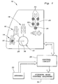
- Fig. 1 shows a portion of a vehicle control panel 10 for a vehicle (not shown) having wheels (not shown) and a steering system (not shown) which is capable of steering the vehicle in a plurality of steering modes.
- Panel 10 includes a steering mode select switch 12.
- Switch 12 is preferably a dual motion switch, such as a commercially available push-to-turn switch.
- the portion of panel 10 includes a crab steer symbol 14, a 2 wheel steer symbol 16 and a 4 wheel steer symbol 18.
- Panel 10 also includes a wheel or axle alignment symbol 20 with openings behind which are mounted lamps or LEDs, including a pair of front wheel alignment lamps 22, a pair of rear wheel alignment lamps 24 and an alignment "system on" lamp 26.
- the switch 12 has a knob 28 with an alignment mark 30 which will point to one of the symbols 14 -18 as it is rotated to actuate the corresponding steering mode.
- the switch 12 and the lamps 22 - 26 are connected to a control circuit 32, which is connected to wheel alignment sensors 33 and to steering mode control solenoids 34.
- the crab steer symbol 14 is preferably illuminated by a lamp or LED 15.
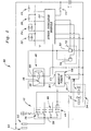
- the switch 12 includes a first set of contacts 36 connected to a crab steer solenoid 38, a second, unused set of contacts, a third set of contacts 40 connected to a 4 wheel steer solenoid 42, and a fourth set of contacts 44 connected to a terminal 46 of an axle lamp relay 48.
- the switch element 50 of switch 12 is connected to + 12 volts via fuse 52.
- the first set of contacts 36 are also connected to steer indicator module 54.
- Relay 48 also includes a terminal 56 connected to a terminal B1 of module timer unit 58.
- Timer unit 58 includes a terminal A1 connected to + 12 volts via fuse 62, a terminal C1 connected to steer indicator or lamp control module 54 and to a front axle or wheel alignment sensor 70 and a rear axle or wheel alignment sensor 72, and a terminal B2 connected to ground.
- Timer 58 operates to connect terminal A1 to C1 for a certain time period (thus applying +12 volts to the lamp control module 54 and to the sensors 70 and 72) when +12 volts is applied to terminal B1.
- Relay 48 also includes a terminal 68 connected to timer terminal C1. Sensors 70 and 72 are also connected to ground and to the lamp control module 54.
- Sensors 70 and 72 are preferably steering cylinder (not shown) position sensors, such as commercially available magnetic sensors which generate a signal when the steering cylinder, or wheels (not shown) is centered, which are commercially available from Ognibene SPA, or the equivalent.
- the lamp control module 54 is connected to lamps 15 and 22 - 26, and to +12 volts via headlight switch 74.
- the time period should be long enough to span the time normally required for steering mode changes to be made.
- the relay 48 could possibly be eliminated if the timer 58 were replaced with a timer ??? capable of being reset every time the switch 12 is pushed. ???
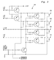
- the lamp control module 54 includes an array of driving transistors connected as shown between, on one hand, sensors 70 and 72, + 12 volts, crab steer solenoid 38, a + 12 volt dimmer control (not shown) and ground, and on the other hand, front wheel alignment lamps 22, rear wheel alignment lamps 24, system "ON" lamp 26 and crab steer lamp 15.
- the above described system actuates the steering mode selected by the switch 12, and additionally controls the lamps 15 and 22 - 26.
- switch 12 Before switch 12 can be turned, it must first be pushed in, and this acts as a reminder to the operator in case the operator desires to coordinate the steering mode change with alignment of the wheels (not shown). Pushing the switch 12 causes the timer 58 to energize the lamp control module 54 for the certain time period, such as 90 seconds, and turns on lamp 26, which indicates to the operator that the lamp control module 54 is "on" and that the indicator lamps 22 -24 can be used in connection with changing the steering mode.
- a signal from the corresponding wheel alignment sensor 70 and/or 72 causes the illumination of the corresponding front/rear wheel alignment lamp 22 and/or 24 on the panel 10.
- These lamps serve as a convenient guide signaling to the operator when it is desirable to change modes.
- the timer 58 times out after the time period expires the lamps 22 - 26 are extinguished.
- the system will change steering modes in response to rotation of knob 28 after the timer 58 times out.
- the steering mode switch 12 is a commercially available three position, push-to-turn, rotary switch with momentary contacts 44 activated by the "push" function.
- the switch 12 cannot be turned without the closing of the momentary contacts 44.
- the control circuit 32 applies current to the crab steer solenoid 38, which places the vehicle (not shown) in a crab steering mode.
- the switch output is 0V and the control circuit 32 de-energizes solenoids 38 and 42, which places the vehicle (not shown) in a 2 wheel steering mode.
- switch 12 is in a third position with mark 30 pointing to 4 wheel steer symbol 18, the control circuit 32 applies current to the 4 wheel steer solenoid 42, which places the vehicle (not shown) in a 4 wheel steering mode.
- the steering mode switch 12 when the steering mode switch 12 is pushed it activates an "alignment mode". This engages the momentary contacts 44 and voltage is applied through relay 48 to the timer 58, which energizes and starts the timer 58. The timer 58 will remain energized for the certain time period, and during this time period the output of timer 58 will be +12 volts, and + 12 volts will be applied to the steering indicator module 54. The energizing of the timer 58 also energizes relay 48, which causes relay 48 to open and thereby preventing the system from responding to further "pushes" of switch 12. The timer 58 also energizes and activates front wheel alignment sensor 70 and rear wheel alignment sensor 72.
- Lamp 26 is turned on to indicate that the lamp control module 54 is energized and activated.
- the output of corresponding sensor 70,72 goes “low” and module 54 turns on the corresponding lamps 22,24 on the display panel 10.
- a conventional dimmer control (not shown) may be used to dim the lamps 22-26 during the night.
- knob 28 If timer 58 times out (the certain time period expires) before knob 28 is turned, the module 54 is de-activated and the lamps 22-26 will not turn on, even when the front or rear wheels are centered.
Landscapes
- Engineering & Computer Science (AREA)
- Chemical & Material Sciences (AREA)
- Combustion & Propulsion (AREA)
- Transportation (AREA)
- Mechanical Engineering (AREA)
- Steering Controls (AREA)
- Lighting Device Outwards From Vehicle And Optical Signal (AREA)
Abstract
Description
- The invention relates to a steering mode selection control system for a vehicle having a plurality of steering modes activated by steering mode actuators. The control system having an operator controlled steering mode select device connected to the steering mode actuators, and a control circuit operatively connected to the mode select device and to at least one wheel alignment and/or mode indicator.
- Various types of vehicles, including telescopic handler vehicles, or "telehandlers", have four wheel drive, four wheel Ackermann type steering and multiple steering modes. These steering modes can include a 4-wheel steering mode for tight situations (wherein the front wheels steer opposite to the rear wheels), a 2-wheel steering mode for road travel (wherein only the front wheels are steered), and a 4-wheel crab steer mode (wherein the front and rear wheels turn in the same direction) so that the vehicle moves in a different direction, but its orientation does not change.
- Various apparatus and means for switching between these different steering modes are known. For example, it is known to use a solenoid operated three position valve to control fluid communication from a steering valve to the front and/or rear axle steering actuators. It is also known to use electrical switches to control the operation of the three position valve, and with such a system the operator may choose to look at the position of the wheels and switch between steering modes when the wheels are judged to be in a straight orientation. Some known production vehicles include a steering position sensor and illuminate a lamp on the operator console to provide the operator with information as to whether or not the wheels are straight. It is know to use sensors on both axles and two lamps, one for each axle.
- It is also known to use various types of switches or control devices to switch between modes, the most common being a rocker or rotary switch. It is also known to use a separate switch to disable the indicator lamps when not in the process of switching between steering modes. Also known are automated systems which permit pre-selection of the desired steering mode, but wherein the steering mode is not actually changed until the wheels are steered to the center. With such automated systems, the operator is not provided with an indication of the position of the wheels.
- There are certain problems associated with these known designs. For example, the steering mode can be accidentally or inadvertently changed by incidental contact with the switch. This could result in an undesired movement of the vehicle. Also, in the systems with the indicator lamps, the lamps are illuminated each time the wheels are steered through the straight ahead position. This illumination of the lamps is potentially distracting to the operator and does not provide any advantages during normal machine operation.
- Accordingly, an object of this invention is to provide a vehicle steering mode selection control which prevents accidental or inadvertent changing of the steering mode. A further object of the invention is to provide such a vehicle steering mode selection control which prevents unnecessary illumination of indicator lights. Another object is to provide a vehicle steering mode selection control which has a simple to understand and operate single switch control.
- These and other objects are achieved by the present invention according to
claim 1. Further advantageous arrangements and developments of the invention appear from the dependent claims. - In an advantageous embodiment of the present invention the vehicle steering mode selection control includes a dual motion (push to turn) rotary switch which cooperates with a timer circuit, a lamp control unit, wheel alignment sensors, wheel alignment lamps, and a "system on" lamp. To change modes, the operator pushes the switch so that it can be turned to select a different steering mode. Pushing the switch starts the timer, activates the wheel alignment sensors, activates or energizes the lamp control unit for a limited time period and illuminates the "system on" lamp, indicating that the wheel alignment sensors and the lamp control unit are ready for use by the operator. When the wheels are steered to the centered or straight ahead position, the wheel alignment sensors and the lamp control unit cooperate to illuminate the corresponding wheel alignment lamps so that the operator can rotate the switch to change steering modes knowing that the wheels associated with the illuminated lamp are aligned straight. The timer provides a limited, pre-determined length of time for making the steering mode change with the assistance of the wheel alignment lamps. When the timer times out, all the wheel alignment lamps are kept off, but the operator can still change steering modes without the assistance of the wheel alignment lamps. If the operator chooses to push the switch and then immediately turn it to change the steering mode (without checking the status of the lamps), the system will immediately respond and change the steering mode as commanded. If timer times out before the switch is turned, the sensors and lamp control unit are de-activated, but the operator can still change steering modes without the assistance of the wheel alignment lamps. Since the switch must be pushed before it can be turned, and pushing the switch activates the timer, the wheel alignment lamps are always activated and available when steering modes are being changed.
- The invention and further advantageous developments and arrangements of the invention will now be described and explained in more detail by way of example and with reference to the accompanying drawings in which:
- Fig. 1
- is a view of a portion of an operator's control panel showing a steering mode select switch and indicator displays according to the present invention,
- Fig. 2
- is an electrical schematic diagram of the steering mode and indicator light control circuit of Fig. 1 and
- Fig. 3
- is an electrical schematic diagram of the steer indicator module of Fig. 2.
- Fig. 1 shows a portion of a
vehicle control panel 10 for a vehicle (not shown) having wheels (not shown) and a steering system (not shown) which is capable of steering the vehicle in a plurality of steering modes.Panel 10 includes a steeringmode select switch 12. Switch 12 is preferably a dual motion switch, such as a commercially available push-to-turn switch. The portion ofpanel 10 includes acrab steer symbol 14, a 2wheel steer symbol 16 and a 4wheel steer symbol 18.Panel 10 also includes a wheel oraxle alignment symbol 20 with openings behind which are mounted lamps or LEDs, including a pair of frontwheel alignment lamps 22, a pair of rearwheel alignment lamps 24 and an alignment "system on"lamp 26. Theswitch 12 has aknob 28 with analignment mark 30 which will point to one of the symbols 14 -18 as it is rotated to actuate the corresponding steering mode. Theswitch 12 and the lamps 22 - 26 are connected to acontrol circuit 32, which is connected towheel alignment sensors 33 and to steeringmode control solenoids 34. Thecrab steer symbol 14 is preferably illuminated by a lamp orLED 15. - Referring now to Fig. 2, the
switch 12 includes a first set ofcontacts 36 connected to acrab steer solenoid 38, a second, unused set of contacts, a third set ofcontacts 40 connected to a 4wheel steer solenoid 42, and a fourth set ofcontacts 44 connected to aterminal 46 of anaxle lamp relay 48. Theswitch element 50 ofswitch 12 is connected to + 12 volts viafuse 52. The first set ofcontacts 36 are also connected tosteer indicator module 54. -
Relay 48 also includes aterminal 56 connected to a terminal B1 ofmodule timer unit 58.Timer unit 58 includes a terminal A1 connected to + 12 volts viafuse 62, a terminal C1 connected to steer indicator orlamp control module 54 and to a front axle orwheel alignment sensor 70 and a rear axle orwheel alignment sensor 72, and a terminal B2 connected to ground.Timer 58 operates to connect terminal A1 to C1 for a certain time period (thus applying +12 volts to thelamp control module 54 and to thesensors 70 and 72) when +12 volts is applied to terminal B1.Relay 48 also includes aterminal 68 connected to timer terminal C1.Sensors lamp control module 54.Sensors lamp control module 54 is connected tolamps 15 and 22 - 26, and to +12 volts viaheadlight switch 74. The time period should be long enough to span the time normally required for steering mode changes to be made. Therelay 48 could possibly be eliminated if thetimer 58 were replaced with a timer ??? capable of being reset every time theswitch 12 is pushed. ??? - Referring to Fig. 3, the
lamp control module 54 includes an array of driving transistors connected as shown between, on one hand,sensors crab steer solenoid 38, a + 12 volt dimmer control (not shown) and ground, and on the other hand, frontwheel alignment lamps 22, rearwheel alignment lamps 24, system "ON"lamp 26 andcrab steer lamp 15. - The above described system actuates the steering mode selected by the
switch 12, and additionally controls thelamps 15 and 22 - 26. Beforeswitch 12 can be turned, it must first be pushed in, and this acts as a reminder to the operator in case the operator desires to coordinate the steering mode change with alignment of the wheels (not shown). Pushing theswitch 12 causes thetimer 58 to energize thelamp control module 54 for the certain time period, such as 90 seconds, and turns onlamp 26, which indicates to the operator that thelamp control module 54 is "on" and that the indicator lamps 22 -24 can be used in connection with changing the steering mode. When the front or rear wheels (not shown) are centered, a signal from the correspondingwheel alignment sensor 70 and/or 72 causes the illumination of the corresponding front/rearwheel alignment lamp 22 and/or 24 on thepanel 10. These lamps serve as a convenient guide signaling to the operator when it is desirable to change modes. When thetimer 58 times out after the time period expires, the lamps 22 - 26 are extinguished. However, the system will change steering modes in response to rotation ofknob 28 after thetimer 58 times out. - Preferably, the
steering mode switch 12 is a commercially available three position, push-to-turn, rotary switch withmomentary contacts 44 activated by the "push" function. Theswitch 12 cannot be turned without the closing of themomentary contacts 44. Whenswitch 12 is in a first position withmark 30 pointing tocrab steer symbol 14, thecontrol circuit 32 applies current to thecrab steer solenoid 38, which places the vehicle (not shown) in a crab steering mode. Whenswitch 12 is in a second position withmark 30 pointing to 2wheel steer symbol 16, the switch output is 0V and thecontrol circuit 32de-energizes solenoids switch 12 is in a third position withmark 30 pointing to 4wheel steer symbol 18, thecontrol circuit 32 applies current to the 4wheel steer solenoid 42, which places the vehicle (not shown) in a 4 wheel steering mode. - More specifically, when the
steering mode switch 12 is pushed it activates an "alignment mode". This engages themomentary contacts 44 and voltage is applied throughrelay 48 to thetimer 58, which energizes and starts thetimer 58. Thetimer 58 will remain energized for the certain time period, and during this time period the output oftimer 58 will be +12 volts, and + 12 volts will be applied to thesteering indicator module 54. The energizing of thetimer 58 also energizesrelay 48, which causesrelay 48 to open and thereby preventing the system from responding to further "pushes" ofswitch 12. Thetimer 58 also energizes and activates frontwheel alignment sensor 70 and rearwheel alignment sensor 72.Lamp 26 is turned on to indicate that thelamp control module 54 is energized and activated. When the front or rear wheels are centered, the output of correspondingsensor module 54 turns on the correspondinglamps display panel 10. A conventional dimmer control (not shown) may be used to dim the lamps 22-26 during the night. - If
timer 58 times out (the certain time period expires) beforeknob 28 is turned, themodule 54 is de-activated and the lamps 22-26 will not turn on, even when the front or rear wheels are centered. - While the present invention has been described in conjunction with a specific embodiment, it is understood that many alternatives, modifications and variations will be apparent to those skilled in the art in light of the foregoing description. Accordingly, this invention is intended to embrace all such alternatives, modifications and variations which fall within the spirit and scope of the appended claims.
Claims (10)
- A steering mode selection control system for a vehicle having a plurality of steering modes activated by steering mode actuators (34), the control system having an operator controlled steering mode select device (12) connected to the steering mode actuators (34), and a control circuit (32) operatively connected to the mode select device (12) and to at least one wheel alignment and/or mode indicator (15, 22, 24), wherein:the steering mode select device (12) comprises a multiple motion device which must be moved in a first manner before it can be moved in a second manner; andthe control circuit (32) comprises a timer (58) and an indicator control unit (54), the timer (58) being actuated for a certain time period in response to movement of the steering mode select device (12) in said first manner, the timer (12) cooperating with the indicator control unit (54) to permit activation of the wheel alignment and/or mode indicator (15, 22, 24) only during said time period.
- The vehicle steering mode selection control system of claim 1, wherein:
the timer (58) is connected to the steering mode select device (12) and an indicator control unit (54) is connected to the timer (58) and to the wheel alignment and/or mode indicator (15, 22, 24). - The vehicle steering mode selection control system of claim 1 or 2, wherein:
the timer (58) is energizing the indicator control unit (54) for a certain time period in response to movement of the steering mode select device (12) in said first manner. - The vehicle steering mode selection control system according to one or more of the preceding claims, wherein:
the multiple motion device is a dual motion device (12) which must be moved in a first manner before it can be moved in a second manner to change a steering mode of the vehicle. - The vehicle steering mode selection control system according to one or more of the preceding claims, wherein:
the steering mode select device comprises a push-to-turn rotary switch (12). - The vehicle steering mode selection control system according to one or more of the preceding claims, wherein:
the steering mode select device comprises a push-to-turn rotary switch (12) which must be pushed before it can be rotated to change a steering mode of the vehicle. - The vehicle steering mode selection control system according to one or more of the preceding claims, wherein:
a relay (48) is connected between the steering mode select device (12) and the timer (58) to prevent the timer (58) from responding during said time period to further movements of the steering mode select device (12) in said first manner. - The vehicle steering mode selection control system according to one or more of the preceding claims, wherein:
a system "ON" indicator (26) is connected to the indicator control unit (54), the indicator control unit (54) and the timer (58) cooperating to energize the "ON" indicator (26) during said time period in response to the steering mode select device (12) being moved in said first manner. - The vehicle steering mode selection control system according to one of the claims 5 to 8 wherein:
a system "ON" indicator (26) is connected to the indicator control unit (54), the indicator control unit (54) and the timer (58) cooperating to energize the "ON" indicator (26) during said time period in response to the switch (12) being pushed. - The vehicle steering mode selection control system according to one or more of the preceding claims, wherein:
the wheel alignment and/or mode indicator (15, 22, 24) is operable to indicate an alignment status of vehicle wheels.
Applications Claiming Priority (2)
| Application Number | Priority Date | Filing Date | Title |
|---|---|---|---|
| US609659 | 2000-06-30 | ||
| US09/609,659 US6424054B1 (en) | 2000-06-30 | 2000-06-30 | Vehicle steering mode selection control |
Publications (2)
| Publication Number | Publication Date |
|---|---|
| EP1167162A2 true EP1167162A2 (en) | 2002-01-02 |
| EP1167162A3 EP1167162A3 (en) | 2004-03-31 |
Family
ID=24441749
Family Applications (1)
| Application Number | Title | Priority Date | Filing Date |
|---|---|---|---|
| EP01115259A Withdrawn EP1167162A3 (en) | 2000-06-30 | 2001-06-23 | Steering mode selection control |
Country Status (4)
| Country | Link |
|---|---|
| US (1) | US6424054B1 (en) |
| EP (1) | EP1167162A3 (en) |
| BR (1) | BR0102617A (en) |
| CA (1) | CA2329470A1 (en) |
Families Citing this family (7)
| Publication number | Priority date | Publication date | Assignee | Title |
|---|---|---|---|---|
| US7278511B1 (en) | 2003-01-27 | 2007-10-09 | Polaris Industries Inc. | Controller for steering a vehicle |
| US7316288B1 (en) | 2003-01-27 | 2008-01-08 | Polaris Industries Inc. | All terrain vehicle with multiple steering modes |
| CN100386480C (en) * | 2005-10-31 | 2008-05-07 | 三一重工股份有限公司 | Method of double handle screening control for walking speed of engineering machinery |
| CN100386481C (en) * | 2005-12-30 | 2008-05-07 | 三一重工股份有限公司 | Control method and device for single-handle and double-handle switchable steering of milling machine |
| US8781685B2 (en) | 2012-07-17 | 2014-07-15 | Agjunction Llc | System and method for integrating automatic electrical steering with GNSS guidance |
| US9254866B2 (en) * | 2013-11-08 | 2016-02-09 | GM Global Technology Operations LLC | Method of controlling steering of a ground vehicle |
| CN111065795B (en) * | 2017-10-12 | 2022-05-24 | 三菱重工业株式会社 | Service menu prompt system and method for power generation equipment, operation mode display system and storage medium |
Family Cites Families (14)
| Publication number | Priority date | Publication date | Assignee | Title |
|---|---|---|---|---|
| US2981808A (en) * | 1958-07-08 | 1961-04-25 | Gen Electric | Interval timer |
| US3750834A (en) * | 1971-12-22 | 1973-08-07 | Int Harvester Co | Steering system |
| US4037490A (en) | 1976-01-02 | 1977-07-26 | General Electric Company | Two-step control knob operation |
| US4090581A (en) * | 1976-11-04 | 1978-05-23 | Detroit Tool And Engineering Company | Carrier vehicle steering system |
| US4893689A (en) * | 1987-07-02 | 1990-01-16 | Laurich Trost Victor | Method and apparatus for steering a motor vehicle |
| US5076382A (en) * | 1989-06-23 | 1991-12-31 | Trw Inc. | Method and apparatus for steering a vehicle |
| JPH0481363A (en) * | 1990-07-20 | 1992-03-16 | Toyota Motor Corp | Rear wheel steering controller for four-wheel steered vehicle |
| US5492353A (en) * | 1990-10-01 | 1996-02-20 | Leonard Studio Equipment, Inc. | Wheel suspension for a camera dolly |
| JP3033314B2 (en) * | 1992-01-14 | 2000-04-17 | トヨタ自動車株式会社 | Vehicle running characteristics control device |
| GB2263451B (en) | 1992-01-17 | 1995-05-17 | D J Ind Ltd | Vehicle with front and rear steering |
| GB2263270B (en) | 1992-01-20 | 1995-01-11 | D J Ind Ltd | Load handling apparatus |
| US5526891A (en) | 1995-03-31 | 1996-06-18 | Caterpillar Inc. | Steering control arrangement |
| US5752578A (en) | 1996-05-07 | 1998-05-19 | Caterpillar Inc. | Control apparatus |
| IT1296535B1 (en) * | 1997-09-29 | 1999-07-02 | Fki Fai Komatsu Ind Spa | ELECTRONIC CONTROL DEVICE FOR THE MANAGEMENT OF THE STEERING IN EARTH-MOVING MACHINES. |
-
2000
- 2000-06-30 US US09/609,659 patent/US6424054B1/en not_active Expired - Fee Related
- 2000-12-20 CA CA002329470A patent/CA2329470A1/en not_active Abandoned
-
2001
- 2001-06-23 EP EP01115259A patent/EP1167162A3/en not_active Withdrawn
- 2001-06-28 BR BR0102617-8A patent/BR0102617A/en not_active IP Right Cessation
Non-Patent Citations (1)
| Title |
|---|
| None |
Also Published As
| Publication number | Publication date |
|---|---|
| US6424054B1 (en) | 2002-07-23 |
| CA2329470A1 (en) | 2001-12-30 |
| BR0102617A (en) | 2002-02-13 |
| EP1167162A3 (en) | 2004-03-31 |
Similar Documents
| Publication | Publication Date | Title |
|---|---|---|
| KR20050024189A (en) | Vehicular Turning Indicator | |
| KR20050063726A (en) | Automobile indicator | |
| US6034600A (en) | Turn signal system and method with steering wheel mounted control of conventional and lane shift indications | |
| US6424054B1 (en) | Vehicle steering mode selection control | |
| US20150035435A1 (en) | Light switch unit for controlling exterior lighting of a motor vehicle | |
| US4191939A (en) | Vehicle parking signaling device | |
| EP0620791B1 (en) | Vehicle with front and rear steering | |
| US20040183462A1 (en) | Control circuit for signal lamps of a vehicle | |
| US12576778B2 (en) | Indicator apparatus for vehicle | |
| US5202581A (en) | Windshield wiper and headlight control circuit | |
| US6693526B1 (en) | Brake light system for a vehicle | |
| US7973484B2 (en) | Method and device for automatically switching to main beam | |
| CN113464645B (en) | Gear shift device | |
| JPH0667158U (en) | Vehicle status display | |
| KR200200220Y1 (en) | A traffic indicator | |
| JPS6343145Y2 (en) | ||
| KR0153740B1 (en) | Emergency lamp | |
| JPS6334998Y2 (en) | ||
| KR100189433B1 (en) | Direction indicating lamp | |
| JPH01156149A (en) | Apparatus and method for indicating direction | |
| JP2025079368A (en) | Lighting control system | |
| KR0124381Y1 (en) | An apparatus for illuminating a cluster of a car | |
| KR100187854B1 (en) | Emergency lamp and turn signal lamp | |
| JPH0478619A (en) | Maloperation preventive device of power take-off for special equipped car | |
| KR20260004050A (en) | controlling apparatus for lamps of vehicle |
Legal Events
| Date | Code | Title | Description |
|---|---|---|---|
| PUAI | Public reference made under article 153(3) epc to a published international application that has entered the european phase |
Free format text: ORIGINAL CODE: 0009012 |
|
| AK | Designated contracting states |
Kind code of ref document: A2 Designated state(s): AT BE CH CY DE DK ES FI FR GB GR IE IT LI LU MC NL PT SE TR |
|
| AX | Request for extension of the european patent |
Free format text: AL;LT;LV;MK;RO;SI |
|
| PUAL | Search report despatched |
Free format text: ORIGINAL CODE: 0009013 |
|
| AK | Designated contracting states |
Kind code of ref document: A3 Designated state(s): AT BE CH CY DE DK ES FI FR GB GR IE IT LI LU MC NL PT SE TR |
|
| AX | Request for extension of the european patent |
Extension state: AL LT LV MK RO SI |
|
| 17P | Request for examination filed |
Effective date: 20040930 |
|
| AKX | Designation fees paid |
Designated state(s): DE ES FI FR GB IT |
|
| GRAP | Despatch of communication of intention to grant a patent |
Free format text: ORIGINAL CODE: EPIDOSNIGR1 |
|
| STAA | Information on the status of an ep patent application or granted ep patent |
Free format text: STATUS: THE APPLICATION IS DEEMED TO BE WITHDRAWN |
|
| 18D | Application deemed to be withdrawn |
Effective date: 20080103 |